EP3322900B1 - Motorverdichter mit einer dränungsanordnung - Google Patents
Motorverdichter mit einer dränungsanordnung Download PDFInfo
- Publication number
- EP3322900B1 EP3322900B1 EP16738816.4A EP16738816A EP3322900B1 EP 3322900 B1 EP3322900 B1 EP 3322900B1 EP 16738816 A EP16738816 A EP 16738816A EP 3322900 B1 EP3322900 B1 EP 3322900B1
- Authority
- EP
- European Patent Office
- Prior art keywords
- motorcompressor
- pipe
- stage
- duct
- drainage
- Prior art date
- Legal status (The legal status is an assumption and is not a legal conclusion. Google has not performed a legal analysis and makes no representation as to the accuracy of the status listed.)
- Active
Links
Images


Classifications
-
- F—MECHANICAL ENGINEERING; LIGHTING; HEATING; WEAPONS; BLASTING
- F04—POSITIVE - DISPLACEMENT MACHINES FOR LIQUIDS; PUMPS FOR LIQUIDS OR ELASTIC FLUIDS
- F04D—NON-POSITIVE-DISPLACEMENT PUMPS
- F04D17/00—Radial-flow pumps, e.g. centrifugal pumps; Helico-centrifugal pumps
- F04D17/08—Centrifugal pumps
- F04D17/10—Centrifugal pumps for compressing or evacuating
- F04D17/12—Multi-stage pumps
-
- F—MECHANICAL ENGINEERING; LIGHTING; HEATING; WEAPONS; BLASTING
- F04—POSITIVE - DISPLACEMENT MACHINES FOR LIQUIDS; PUMPS FOR LIQUIDS OR ELASTIC FLUIDS
- F04D—NON-POSITIVE-DISPLACEMENT PUMPS
- F04D25/00—Pumping installations or systems
- F04D25/02—Units comprising pumps and their driving means
- F04D25/06—Units comprising pumps and their driving means the pump being electrically driven
- F04D25/0686—Units comprising pumps and their driving means the pump being electrically driven specially adapted for submerged use
-
- F—MECHANICAL ENGINEERING; LIGHTING; HEATING; WEAPONS; BLASTING
- F04—POSITIVE - DISPLACEMENT MACHINES FOR LIQUIDS; PUMPS FOR LIQUIDS OR ELASTIC FLUIDS
- F04D—NON-POSITIVE-DISPLACEMENT PUMPS
- F04D29/00—Details, component parts, or accessories
- F04D29/70—Suction grids; Strainers; Dust separation; Cleaning
- F04D29/701—Suction grids; Strainers; Dust separation; Cleaning especially adapted for elastic fluid pumps
- F04D29/705—Adding liquids
-
- F—MECHANICAL ENGINEERING; LIGHTING; HEATING; WEAPONS; BLASTING
- F04—POSITIVE - DISPLACEMENT MACHINES FOR LIQUIDS; PUMPS FOR LIQUIDS OR ELASTIC FLUIDS
- F04D—NON-POSITIVE-DISPLACEMENT PUMPS
- F04D29/00—Details, component parts, or accessories
- F04D29/70—Suction grids; Strainers; Dust separation; Cleaning
- F04D29/701—Suction grids; Strainers; Dust separation; Cleaning especially adapted for elastic fluid pumps
- F04D29/706—Humidity separation
-
- F—MECHANICAL ENGINEERING; LIGHTING; HEATING; WEAPONS; BLASTING
- F04—POSITIVE - DISPLACEMENT MACHINES FOR LIQUIDS; PUMPS FOR LIQUIDS OR ELASTIC FLUIDS
- F04D—NON-POSITIVE-DISPLACEMENT PUMPS
- F04D31/00—Pumping liquids and elastic fluids at the same time
-
- F—MECHANICAL ENGINEERING; LIGHTING; HEATING; WEAPONS; BLASTING
- F04—POSITIVE - DISPLACEMENT MACHINES FOR LIQUIDS; PUMPS FOR LIQUIDS OR ELASTIC FLUIDS
- F04F—PUMPING OF FLUID BY DIRECT CONTACT OF ANOTHER FLUID OR BY USING INERTIA OF FLUID TO BE PUMPED; SIPHONS
- F04F5/00—Jet pumps, i.e. devices in which flow is induced by pressure drop caused by velocity of another fluid flow
- F04F5/02—Jet pumps, i.e. devices in which flow is induced by pressure drop caused by velocity of another fluid flow the inducing fluid being liquid
- F04F5/10—Jet pumps, i.e. devices in which flow is induced by pressure drop caused by velocity of another fluid flow the inducing fluid being liquid displacing liquids, e.g. containing solids, or liquids and elastic fluids
Definitions
- the subject matter of the present disclosure relates to a turbomachine.
- the embodiments of the invention will be described specifically as applied to a subsea motorcompressor, however this will be done without losing the general approach.
- a subsea motorcompressor comprises an electric motor and an operating portion, itself comprising a rotor.
- the operating portion can be a centrifugal compressor.
- a shaft is connected to both the electric motor and the rotor.
- the rotor comprises a plurality of compression stages connected to the shaft. Each stage has an intake and a discharge duct for a process fluid.
- the motorcompressor stages are also placed in fluid communication with each other serially, so that the discharge of each stage feeds the intake of the next.
- a compressor assembly including a separator and an ejector pump. The separator separates a multiphase fluid stream into a substantially liquid portion which is then sent to a liquid reservoir and a substantially gaseous stream.
- An inlet of a compressor is fluidly coupled with an outlet of the separator to receive and pressurize the substantially gaseous portion of the multiphase fluid stream and an outlet of the compressor is configured to discharge a pressurized gas.
- An ejector pump receives a portion of the pressurized gas from the compressor to draw in a flow of the substantially liquid portion of the multiphase fluid stream from the liquid reservoir and discharge a combined stream of liquid and pressurized gas.
- a fluid discharge line is fluidly coupled to the compressor outlet and receives the pressurized gas from the compressor and the combined stream of liquid and pressurized gas from the ejector pump to form a pressurized multiphase fluid stream.
- the sump can then be drained through a flange on the bottom connected to an external pumping device through a valve.
- the drainage operation is not automatized, as it requires the intervention of the operator.
- the current system requires that the motorcompressor be taken offline for drainage.
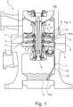
- the motorcompressor 2 comprises a plurality of stages 3. Each stage 3 has a duct 4 for a process fluid.
- the duct 4 has an intake 5 and a discharge section 6 for the process fluid.
- Inside the duct 4, each stage 3 is provided with a rotating element 7, which can be, depending on the kind of machine, either a rotor of a turbine or an impeller of a compressor.
- the stages 3 are arranged serially.
- the discharge section 6 of the duct 4 of each stage 3 is placed in direct fluid communication with the intake section 5 of the duct 4 of the next stage 3. Therefore, each stage 3 compresses the process fluid which is discharged by the previous stage 3 in the sequence.
- the rotating elements 7 of all the stages 3 are attached onto a single shaft 8.
- the shaft 8 has a rotation axis "A". Also, in order to provide and/or extract energy to the rotating elements 7, the shaft 8 is connected to an engine or to a generator (both are not shown in the drawings). According to another embodiment, not shown in the drawings, there is no shaft and the stages 3 are attached to one another.
- the stages 3 are assembled in a vertical orientation.
- the shaft 8 is oriented vertically.
- the motorcompressor 2 also comprises a drainage sump 9.
- the drainage sump 9 is placed at the bottom, below all the stages 3. In the configuration of the motorcompressor 2 shown in the figures, the sump 9 is placed below the lowest stage 3, in which is the process fluid has the highest pressure.
- the motorcompressor 2 also comprises a droplet/solid particles separator 11 upstream of the first stage 3.
- the motorcompressor 2 is provided with an external casing 12, which encloses all the above mentioned components and protects them from the outside environment.
- the apparatus 1 is installed inside the motorcompressor 2 just described.
- the apparatus 1 comprises a first pipe 10.
- the first pipe 10 has a first end 10a, which is configured to be inserted in the drainage sump 9 of the motorcompressor 2.
- the first pipe 10 also has a second end 10b, which is configured to be connected to the stage 3 or to the inlet duct of the motorcompressor 2.
- the second end 10b of the first pipe 10 is attached to the intake section 5 of the stage 3. More preferably, the second end 10b of the first pipe 10 is attached to the intake section 5 of the duct 4 of the first stage of the motorcompressor 2.
- the first pipe 10 is also enclosed by the casing 12 of the motorcompressor.
- the apparatus 1 also comprises a device 13 for generating a pressure difference between the second 10b and the first end 10a of the first pipe 10.
- the device 13 comprises a second pipe 14.
- Such second pipe 14 has a first end 14a, which is configured to be connected to a high pressure zone 15 of the motorcompressor 2.
- a "high pressure zone” is defined as any part of the motorcompressor 2 in which the process fluid has a pressure higher than the compressor suction pressure.
- the high pressure zone 15 can be a discharge section 6 of a duct 4 of any stage 3.
- the high pressure zone 15 can be a downward section of compression suction, for example just downstream the droplet separator 11.
- the second pipe 14 also has a second end 14b, which is fluidly connected to said first pipe 10 at an intermediate point between said first and second ends 10a, 10b.
- the second pipe takes a portion of the process fluid from inside the motorcompressor 2 and delivers it inside the first pipe 10.
- the second end 14b of the second pipe 14 has a convergent portion 16, so that it can accelerate the process fluid which is delivered into the first pipe 10. Furthermore, the second end 14b of the second pipe 14 is arranged so that the process fluid discharged from it is directed towards the second end 10b of the first pipe 10. In this way, the acceleration creates a suction effect inside the first pipe 10, thus allowing the extraction of discharged liquid from the sump 9.
- This approach allows to create a pressure difference between the two ends of the first pipe 10 that is up to half of the pressure in the high pressure zone.
- the second pipe 14 is placed inside the casing 12 of the motorcompressor 2.
Landscapes
- Engineering & Computer Science (AREA)
- Mechanical Engineering (AREA)
- General Engineering & Computer Science (AREA)
- Physics & Mathematics (AREA)
- Fluid Mechanics (AREA)
- Structures Of Non-Positive Displacement Pumps (AREA)
Claims (8)
- Motorkompressor (2) umfassend einen Entwässerungssumpf (9); eine Vielzahl von Stufen, die jeweils einen Kanal (4) mit einem Ansaugtrakt (5) und einem Abflussbereich (6) für ein Prozessfluid aufweisen; eine Entwässerungseinrichtung (1), die in Fluidverbindung mit dem Entwässerungssumpf (9) und mit einem Kanal einer der Stufen (3) steht, die Entwässerungseinrichtung (1) umfassend ein erstes Rohr (10) umfasst, das in einem externen Gehäuse (12) platziert ist und das ein erstes Ende (10a), das in einen Entwässerungssumpf (9) des Motorkompressors (2) eingesetzt ist und ein zweites Ende (10b), das in Fluidverbindung mit dem Ansaugtrakt (5) eines Kanals (4) einer Stufe (3) des Motorkompressors (2) steht, aufweist; wobei der Ansaugtrakt (5) stromaufwärts von einem rotierenden Elements (7) im Inneren des Kanals (4) der Stufe (3) ist, damit ein Prozessfluid zu dem rotierenden Elements (7) hin geleitet werden kann, und wobei die Einrichtung (1) eine Vorrichtung (13) zum Erzeugen einer Druckdifferenz zwischen dem zweiten Ende (10b) und dem ersten Ende (10a) umfasst, so dass das Prozessfluid aus dem Entwässerungssumpf (9) entnommen und in den Ansaugtrakt (5) des Kanals (4) geleitet wird.
- Motorkompressor (2) nach dem vorstehenden Anspruch, wobei die Vorrichtung (13) zum Erzeugen einer Druckdifferenz ein zweites Rohr (14), das ein erstes Ende (14a) aufweist, das konfiguriert ist, um mit dem Abflussbereich (6) des Kanals (4) einer Stufe (3) des Motorkompressors (2) fluidisch verbunden zu werden; und ein zweites Ende (14b), das mit dem ersten Rohr (10) an einem Zwischenpunkt zwischen dem ersten und dem zweiten Ende (10a, 10b) fluidisch ist, umfasst.
- Motorkompressor (2) nach dem vorstehenden Anspruch, wobei das zweite Ende (14b) des zweiten Rohrs (14) einen konvergierenden Abschnitt (16) aufweist, um den Druck des Prozessfluids zu verringern, das durch das zweite Ende (14b) des zweiten Rohrs (14) abgegeben wird.
- Motorkompressor (2) nach Anspruch 2 oder 3, wobei der Abflussbereich (6), mit dem das erste Ende (14a) des zweiten Rohrs (14) konfiguriert ist, um fluidisch verbunden zu werden, stromabwärts des rotierenden Elements (7) der Stufe (3) des Motorkompressors (2) ist.
- Motorkompressor (2) nach einem der Ansprüche 2 oder 3, wobei der Abflussbereich (6), mit dem das erste Ende (14a) des zweiten Rohrs (14) konfiguriert ist, um fluidisch verbunden zu werden, ein nach unten gerichteter Kompressions-/Saugbereich ist.
- Motorkompressor (2) nach einem der Ansprüche 2 bis 5, wobei das zweite Ende (14b) des zweiten Rohrs (14) zu dem zweiten Ende (10b) des ersten Rohrs (10) hin gerichtet ist.
- Motorkompressor (2) nach einem der vorstehenden Ansprüche, wobei der Ansaugtrakt (5) der Ansaugtrakt (5) der ersten Stufe (3) ist.
- Motorkompressor (2) nach Anspruch 2 oder einem beliebigen von Anspruch 2 abhängigen Anspruch, wobei das zweite Rohr (14) im Inneren des Gehäuses (12) platziert ist.
Applications Claiming Priority (2)
| Application Number | Priority Date | Filing Date | Title |
|---|---|---|---|
| ITUB2015A002247A ITUB20152247A1 (it) | 2015-07-16 | 2015-07-16 | Apparato di drenaggio per una turbomacchina. |
| PCT/EP2016/066885 WO2017009451A1 (en) | 2015-07-16 | 2016-07-15 | Drainage apparatus for a motorcompressor and motorcompressor therewith |
Publications (2)
| Publication Number | Publication Date |
|---|---|
| EP3322900A1 EP3322900A1 (de) | 2018-05-23 |
| EP3322900B1 true EP3322900B1 (de) | 2025-02-19 |
Family
ID=54251673
Family Applications (1)
| Application Number | Title | Priority Date | Filing Date |
|---|---|---|---|
| EP16738816.4A Active EP3322900B1 (de) | 2015-07-16 | 2016-07-15 | Motorverdichter mit einer dränungsanordnung |
Country Status (6)
| Country | Link |
|---|---|
| US (1) | US10746178B2 (de) |
| EP (1) | EP3322900B1 (de) |
| AU (1) | AU2016293096B2 (de) |
| ES (1) | ES3019810T3 (de) |
| IT (1) | ITUB20152247A1 (de) |
| WO (1) | WO2017009451A1 (de) |
Families Citing this family (3)
| Publication number | Priority date | Publication date | Assignee | Title |
|---|---|---|---|---|
| ITUA20161464A1 (it) * | 2016-03-08 | 2017-09-08 | Nuovo Pignone Tecnologie Srl | Centrifugal compressor without external drainage system, motorcompressor and method of avoiding external drainage in a compressor / Compressore centrifugo senza sistema di drenaggio esterno, motocompressore e metodo per evitare drenaggio esterno in un compressore |
| IT201900023883A1 (it) * | 2019-12-13 | 2021-06-13 | Nuovo Pignone Tecnologie Srl | Compressore con un sistema per rimuovere liquido dal compressore |
| US11624375B2 (en) * | 2021-01-13 | 2023-04-11 | Garrett Transportation I Inc | Moisture removal system for electric compressor device |
Family Cites Families (7)
| Publication number | Priority date | Publication date | Assignee | Title |
|---|---|---|---|---|
| AU462145B2 (en) * | 1970-09-28 | 1975-06-19 | Vaqua Ltd. | Vacuum pump |
| FR2500086A1 (fr) * | 1981-02-13 | 1982-08-20 | Laguilharre Pierre | Installation pour la realisation d'une difference elevee de pression entre deux points, mettant en oeuvre une pompe a anneau liquide simple etage associee a un ejecteur a jet de liquide |
| US4938664A (en) * | 1989-11-13 | 1990-07-03 | Carrier Corporation | Oil reclaim system |
| NO172075C (no) * | 1991-02-08 | 1993-06-02 | Kvaerner Rosenberg As Kvaerner | Fremgangsmaate ved drift av et kompressoranlegg i en undervannstasjon for transport av en broennstroem og kompressoranlegg i en undervannstasjon for transport av en broennstroem |
| US8408879B2 (en) * | 2008-03-05 | 2013-04-02 | Dresser-Rand Company | Compressor assembly including separator and ejector pump |
| JP2011111990A (ja) * | 2009-11-27 | 2011-06-09 | Mitsubishi Heavy Ind Ltd | 遠心圧縮機 |
| US20110223039A1 (en) * | 2010-03-15 | 2011-09-15 | General Electric Company | Pump assembly and method |
-
2015
- 2015-07-16 IT ITUB2015A002247A patent/ITUB20152247A1/it unknown
-
2016
- 2016-07-15 US US15/745,156 patent/US10746178B2/en active Active
- 2016-07-15 EP EP16738816.4A patent/EP3322900B1/de active Active
- 2016-07-15 WO PCT/EP2016/066885 patent/WO2017009451A1/en not_active Ceased
- 2016-07-15 ES ES16738816T patent/ES3019810T3/es active Active
- 2016-07-15 AU AU2016293096A patent/AU2016293096B2/en active Active
Also Published As
| Publication number | Publication date |
|---|---|
| ES3019810T3 (en) | 2025-05-21 |
| US20190010947A1 (en) | 2019-01-10 |
| AU2016293096A1 (en) | 2018-01-25 |
| WO2017009451A1 (en) | 2017-01-19 |
| AU2016293096B2 (en) | 2020-07-02 |
| EP3322900A1 (de) | 2018-05-23 |
| US10746178B2 (en) | 2020-08-18 |
| ITUB20152247A1 (it) | 2017-01-16 |
Similar Documents
| Publication | Publication Date | Title |
|---|---|---|
| JP5536804B2 (ja) | 流体回転機械用のガス送入および取出可逆システム | |
| WO2009111616A2 (en) | Compressor assembly including separator and ejector pump | |
| EP2439412B1 (de) | Flüssigkeitsringverdichter zur Unterwasserverdichtung von Flüssiggasen | |
| EP3256699A1 (de) | Turboexpander-generator-einheit und verfahren zur erzeugung von elektrischer energie | |
| AU2016293096B2 (en) | Drainage apparatus for a motorcompressor and motorcompressor therewith | |
| US6361270B1 (en) | Centrifugal pump for a gas turbine engine | |
| US11248630B2 (en) | Liquid/gas separator and centrifugal motor compressor unit equipped with such a separator | |
| EP2590723B1 (de) | Mehrstufiges trennungssystem | |
| WO2011067665A1 (en) | A compressor unit and a method to process a working fluid | |
| US12006941B2 (en) | Compressor with a system for removing liquid from the compressor | |
| KR20130142541A (ko) | 원심 펌프 | |
| US10830255B2 (en) | Centrifugal compressor without external drainage system, motorcompressor and method of avoiding external drainage in a compressor | |
| CA3160034C (en) | Compressor with a system for removing liquid from the compressor | |
| US8573924B2 (en) | Gas compressor | |
| EP3426928B1 (de) | Radialverdichter ohne externes drainagesystem, motorkompressor und verfahren zum vermeiden von externer drainage bei einem kompressor | |
| EP3298283B1 (de) | Untersee-verdichter mit vorrichtung zur reinigung des motorkühlung-lüfters und/oder von hilfslagern | |
| EA046434B1 (ru) | Компрессор и способ удаления жидкости из компрессора |
Legal Events
| Date | Code | Title | Description |
|---|---|---|---|
| STAA | Information on the status of an ep patent application or granted ep patent |
Free format text: STATUS: THE INTERNATIONAL PUBLICATION HAS BEEN MADE |
|
| PUAI | Public reference made under article 153(3) epc to a published international application that has entered the european phase |
Free format text: ORIGINAL CODE: 0009012 |
|
| STAA | Information on the status of an ep patent application or granted ep patent |
Free format text: STATUS: REQUEST FOR EXAMINATION WAS MADE |
|
| 17P | Request for examination filed |
Effective date: 20180216 |
|
| AK | Designated contracting states |
Kind code of ref document: A1 Designated state(s): AL AT BE BG CH CY CZ DE DK EE ES FI FR GB GR HR HU IE IS IT LI LT LU LV MC MK MT NL NO PL PT RO RS SE SI SK SM TR |
|
| AX | Request for extension of the european patent |
Extension state: BA ME |
|
| DAV | Request for validation of the european patent (deleted) | ||
| DAX | Request for extension of the european patent (deleted) | ||
| STAA | Information on the status of an ep patent application or granted ep patent |
Free format text: STATUS: EXAMINATION IS IN PROGRESS |
|
| 17Q | First examination report despatched |
Effective date: 20210525 |
|
| P01 | Opt-out of the competence of the unified patent court (upc) registered |
Effective date: 20230526 |
|
| GRAP | Despatch of communication of intention to grant a patent |
Free format text: ORIGINAL CODE: EPIDOSNIGR1 |
|
| STAA | Information on the status of an ep patent application or granted ep patent |
Free format text: STATUS: GRANT OF PATENT IS INTENDED |
|
| INTG | Intention to grant announced |
Effective date: 20241118 |
|
| GRAS | Grant fee paid |
Free format text: ORIGINAL CODE: EPIDOSNIGR3 |
|
| GRAA | (expected) grant |
Free format text: ORIGINAL CODE: 0009210 |
|
| STAA | Information on the status of an ep patent application or granted ep patent |
Free format text: STATUS: THE PATENT HAS BEEN GRANTED |
|
| AK | Designated contracting states |
Kind code of ref document: B1 Designated state(s): AL AT BE BG CH CY CZ DE DK EE ES FI FR GB GR HR HU IE IS IT LI LT LU LV MC MK MT NL NO PL PT RO RS SE SI SK SM TR |
|
| RAP3 | Party data changed (applicant data changed or rights of an application transferred) |
Owner name: NUOVO PIGNONE TECNOLOGIE - S.R.L. |
|
| REG | Reference to a national code |
Ref country code: GB Ref legal event code: FG4D |
|
| REG | Reference to a national code |
Ref country code: CH Ref legal event code: EP |
|
| REG | Reference to a national code |
Ref country code: DE Ref legal event code: R096 Ref document number: 602016091273 Country of ref document: DE |
|
| REG | Reference to a national code |
Ref country code: IE Ref legal event code: FG4D |
|
| REG | Reference to a national code |
Ref country code: ES Ref legal event code: FG2A Ref document number: 3019810 Country of ref document: ES Kind code of ref document: T3 Effective date: 20250521 |
|
| REG | Reference to a national code |
Ref country code: NL Ref legal event code: MP Effective date: 20250219 |
|
| PG25 | Lapsed in a contracting state [announced via postgrant information from national office to epo] |
Ref country code: RS Free format text: LAPSE BECAUSE OF FAILURE TO SUBMIT A TRANSLATION OF THE DESCRIPTION OR TO PAY THE FEE WITHIN THE PRESCRIBED TIME-LIMIT Effective date: 20250519 |
|
| PG25 | Lapsed in a contracting state [announced via postgrant information from national office to epo] |
Ref country code: FI Free format text: LAPSE BECAUSE OF FAILURE TO SUBMIT A TRANSLATION OF THE DESCRIPTION OR TO PAY THE FEE WITHIN THE PRESCRIBED TIME-LIMIT Effective date: 20250219 |
|
| PG25 | Lapsed in a contracting state [announced via postgrant information from national office to epo] |
Ref country code: PL Free format text: LAPSE BECAUSE OF FAILURE TO SUBMIT A TRANSLATION OF THE DESCRIPTION OR TO PAY THE FEE WITHIN THE PRESCRIBED TIME-LIMIT Effective date: 20250219 |
|
| PGFP | Annual fee paid to national office [announced via postgrant information from national office to epo] |
Ref country code: GB Payment date: 20250619 Year of fee payment: 10 |
|
| REG | Reference to a national code |
Ref country code: LT Ref legal event code: MG9D |
|
| PG25 | Lapsed in a contracting state [announced via postgrant information from national office to epo] |
Ref country code: IS Free format text: LAPSE BECAUSE OF FAILURE TO SUBMIT A TRANSLATION OF THE DESCRIPTION OR TO PAY THE FEE WITHIN THE PRESCRIBED TIME-LIMIT Effective date: 20250619 |
|
| PGFP | Annual fee paid to national office [announced via postgrant information from national office to epo] |
Ref country code: NO Payment date: 20250623 Year of fee payment: 10 |
|
| PG25 | Lapsed in a contracting state [announced via postgrant information from national office to epo] |
Ref country code: NL Free format text: LAPSE BECAUSE OF FAILURE TO SUBMIT A TRANSLATION OF THE DESCRIPTION OR TO PAY THE FEE WITHIN THE PRESCRIBED TIME-LIMIT Effective date: 20250219 |
|
| PG25 | Lapsed in a contracting state [announced via postgrant information from national office to epo] |
Ref country code: HR Free format text: LAPSE BECAUSE OF FAILURE TO SUBMIT A TRANSLATION OF THE DESCRIPTION OR TO PAY THE FEE WITHIN THE PRESCRIBED TIME-LIMIT Effective date: 20250219 |
|
| PG25 | Lapsed in a contracting state [announced via postgrant information from national office to epo] |
Ref country code: PT Free format text: LAPSE BECAUSE OF FAILURE TO SUBMIT A TRANSLATION OF THE DESCRIPTION OR TO PAY THE FEE WITHIN THE PRESCRIBED TIME-LIMIT Effective date: 20250620 Ref country code: LV Free format text: LAPSE BECAUSE OF FAILURE TO SUBMIT A TRANSLATION OF THE DESCRIPTION OR TO PAY THE FEE WITHIN THE PRESCRIBED TIME-LIMIT Effective date: 20250219 |
|
| PGFP | Annual fee paid to national office [announced via postgrant information from national office to epo] |
Ref country code: FR Payment date: 20250620 Year of fee payment: 10 |
|
| PG25 | Lapsed in a contracting state [announced via postgrant information from national office to epo] |
Ref country code: BG Free format text: LAPSE BECAUSE OF FAILURE TO SUBMIT A TRANSLATION OF THE DESCRIPTION OR TO PAY THE FEE WITHIN THE PRESCRIBED TIME-LIMIT Effective date: 20250219 Ref country code: GR Free format text: LAPSE BECAUSE OF FAILURE TO SUBMIT A TRANSLATION OF THE DESCRIPTION OR TO PAY THE FEE WITHIN THE PRESCRIBED TIME-LIMIT Effective date: 20250520 |
|
| REG | Reference to a national code |
Ref country code: AT Ref legal event code: MK05 Ref document number: 1768501 Country of ref document: AT Kind code of ref document: T Effective date: 20250219 |
|
| PG25 | Lapsed in a contracting state [announced via postgrant information from national office to epo] |
Ref country code: SE Free format text: LAPSE BECAUSE OF FAILURE TO SUBMIT A TRANSLATION OF THE DESCRIPTION OR TO PAY THE FEE WITHIN THE PRESCRIBED TIME-LIMIT Effective date: 20250219 |
|
| PG25 | Lapsed in a contracting state [announced via postgrant information from national office to epo] |
Ref country code: SM Free format text: LAPSE BECAUSE OF FAILURE TO SUBMIT A TRANSLATION OF THE DESCRIPTION OR TO PAY THE FEE WITHIN THE PRESCRIBED TIME-LIMIT Effective date: 20250219 |
|
| PGFP | Annual fee paid to national office [announced via postgrant information from national office to epo] |
Ref country code: ES Payment date: 20250801 Year of fee payment: 10 |
|
| PG25 | Lapsed in a contracting state [announced via postgrant information from national office to epo] |
Ref country code: DK Free format text: LAPSE BECAUSE OF FAILURE TO SUBMIT A TRANSLATION OF THE DESCRIPTION OR TO PAY THE FEE WITHIN THE PRESCRIBED TIME-LIMIT Effective date: 20250219 |
|
| PGFP | Annual fee paid to national office [announced via postgrant information from national office to epo] |
Ref country code: DE Payment date: 20250620 Year of fee payment: 10 |
|
| PG25 | Lapsed in a contracting state [announced via postgrant information from national office to epo] |
Ref country code: IT Free format text: LAPSE BECAUSE OF FAILURE TO SUBMIT A TRANSLATION OF THE DESCRIPTION OR TO PAY THE FEE WITHIN THE PRESCRIBED TIME-LIMIT Effective date: 20250219 |
|
| PG25 | Lapsed in a contracting state [announced via postgrant information from national office to epo] |
Ref country code: AT Free format text: LAPSE BECAUSE OF FAILURE TO SUBMIT A TRANSLATION OF THE DESCRIPTION OR TO PAY THE FEE WITHIN THE PRESCRIBED TIME-LIMIT Effective date: 20250219 |
|
| PGFP | Annual fee paid to national office [announced via postgrant information from national office to epo] |
Ref country code: CH Payment date: 20250801 Year of fee payment: 10 |
|
| PG25 | Lapsed in a contracting state [announced via postgrant information from national office to epo] |
Ref country code: EE Free format text: LAPSE BECAUSE OF FAILURE TO SUBMIT A TRANSLATION OF THE DESCRIPTION OR TO PAY THE FEE WITHIN THE PRESCRIBED TIME-LIMIT Effective date: 20250219 |
|
| PGFP | Annual fee paid to national office [announced via postgrant information from national office to epo] |
Ref country code: CZ Payment date: 20250630 Year of fee payment: 10 |
|
| PG25 | Lapsed in a contracting state [announced via postgrant information from national office to epo] |
Ref country code: RO Free format text: LAPSE BECAUSE OF FAILURE TO SUBMIT A TRANSLATION OF THE DESCRIPTION OR TO PAY THE FEE WITHIN THE PRESCRIBED TIME-LIMIT Effective date: 20250219 |
|
| PG25 | Lapsed in a contracting state [announced via postgrant information from national office to epo] |
Ref country code: SK Free format text: LAPSE BECAUSE OF FAILURE TO SUBMIT A TRANSLATION OF THE DESCRIPTION OR TO PAY THE FEE WITHIN THE PRESCRIBED TIME-LIMIT Effective date: 20250219 |
|
| REG | Reference to a national code |
Ref country code: DE Ref legal event code: R097 Ref document number: 602016091273 Country of ref document: DE |
|
| PLBE | No opposition filed within time limit |
Free format text: ORIGINAL CODE: 0009261 |
|
| STAA | Information on the status of an ep patent application or granted ep patent |
Free format text: STATUS: NO OPPOSITION FILED WITHIN TIME LIMIT |
|
| 26N | No opposition filed |
Effective date: 20251120 |
|
| PG25 | Lapsed in a contracting state [announced via postgrant information from national office to epo] |
Ref country code: LU Free format text: LAPSE BECAUSE OF NON-PAYMENT OF DUE FEES Effective date: 20250715 |
|
| REG | Reference to a national code |
Ref country code: BE Ref legal event code: MM Effective date: 20250731 |
|
| PG25 | Lapsed in a contracting state [announced via postgrant information from national office to epo] |
Ref country code: BE Free format text: LAPSE BECAUSE OF NON-PAYMENT OF DUE FEES Effective date: 20250731 |