EP3265378B1 - Hängende meeresplattform - Google Patents
Hängende meeresplattform Download PDFInfo
- Publication number
- EP3265378B1 EP3265378B1 EP16758394.7A EP16758394A EP3265378B1 EP 3265378 B1 EP3265378 B1 EP 3265378B1 EP 16758394 A EP16758394 A EP 16758394A EP 3265378 B1 EP3265378 B1 EP 3265378B1
- Authority
- EP
- European Patent Office
- Prior art keywords
- marine platform
- spar
- assembly
- spars
- vessel
- Prior art date
- Legal status (The legal status is an assumption and is not a legal conclusion. Google has not performed a legal analysis and makes no representation as to the accuracy of the status listed.)
- Active
Links
Images









Classifications
-
- B—PERFORMING OPERATIONS; TRANSPORTING
- B63—SHIPS OR OTHER WATERBORNE VESSELS; RELATED EQUIPMENT
- B63B—SHIPS OR OTHER WATERBORNE VESSELS; EQUIPMENT FOR SHIPPING
- B63B17/00—Vessels parts, details, or accessories, not otherwise provided for
- B63B17/0081—Vibration isolation or damping elements or arrangements, e.g. elastic support of deck-houses
Definitions
- the present invention relates to a suspended marine platform. More particularly, the present invention relates to a suspended marine passenger platform for use in high-speed watercraft.
- High-speed small boats are used in a variety of applications and are particularly useful in military operations, and search and rescue operations.
- each pitching and acceleration/deceleration cycle may be measured in seconds, such that passengers are subjected to rapid and extreme acceleration and deceleration and the associated shock, which is commonly quantified in terms of multiples of g, a "g" being a unit of acceleration equivalent to that exerted by the earth's gravitational field at the surface of the earth.
- the term g-force is also often used, but it is commonly understood to mean a relatively long-term acceleration.
- a short-term acceleration is usually called a shock and is also quantified in terms of g.
- US Patent No. 6,786,172 (Loffler - Shock absorbing boat) discloses a horizontal base for supporting a steering station that that is hingedly connected to the transom to pivot about a horizontal axis.
- the base is supported by spring bias means connected to the hull.
- WO 2012/129665 (Smith - Suspended marine platform), discloses a shock absorbing assembly for resiliently suspending a marine platform relative to a vessel, having two spar assemblies, one of the spar assemblies forward of the other spar assembly, and each spar assembly comprising a first spar and a second spar, each spar pivotally attached at a proximal end to the vessel and pivotally attached at a distal end to the marine platform with the proximal ends aft of the distal ends and the proximal ends of the spars are spaced athwart one from the other a greater distance than the distal ends of the spars are spaced athwart one from the other.
- Impact attenuation systems for aircraft seats are also known, as disclosed in: US Patent No. 4,349,167 (Reilly - Crash load attenuating passenger seat); US Patent No. 4,523,730 (Martin - Energy-absorbing seat arrangement); US Patent No. 4,911,381 (Cannon et al. - Energy absorbing leg assembly for aircraft passenger seats); US Patent No. 5,125,598 (Fox - Pivoting energy attenuating seat); and US Patent No.5,152,578 - Kiguchi - Leg structure of seat for absorbing impact energy.
- the present invention provides a suspension system for a suspended marine platform on a high-speed water vessel having a usual direction of travel, the suspension system including: a shock absorbing assembly for resiliently suspending a marine platform relative to a vessel, wherein the shock absorbing assembly tends to cause the marine platform to remain in an upper at-rest position and to return to the at-rest position on cessation of a force causing the marine platform to move generally vertically towards a bottom position; two spar assemblies, one of the spar assemblies forward of the other spar assembly, and each spar assembly including a first spar and a second spar, each spar pivotally attached at a proximal end to the vessel and pivotally attached at a distal end to the marine platform, wherein: the proximal ends are aft of the distal ends; and the proximal ends of the spars are spaced athwart one from the other a greater distance than the distal ends of the spars are spaced athwart one from the other; wherein: the attachment of one of the spar
- the attachment of the one of the spar assemblies to the marine platform permits relative fore and aft movement between the marine platform and the distal ends of the spars of that one of the spar assemblies.
- the relative fore and aft movement between the marine platform and the distal ends of the spars of that one of the spar assemblies may be linear.
- the relative fore and aft movement between the marine platform and the distal ends of the spars of that one of the spar assemblies may be provided by a track and car assembly.
- the relative fore and aft movement between the marine platform and the distal ends of the spars of that one of the spar assemblies may be arcuate.
- the relative fore and aft movement between the marine platform and the distal ends of the spars of that one of the spar assemblies may be provided by a pivot assembly.
- the suspension system may include a roll-attenuation assembly interconnected between the marine platform and the vessel.
- the roll-attenuation assembly may include a torsion bar mounted so as to extend athwart, the torsion bar comprising a torsion spring having at each end an arm extending laterally from the torsion spring, wherein the torsion spring is mounted to one of the marine platform and the vessel, and the arms are each interconnected to the other of the marine platform and the vessel.
- the first spar and second spar may be fixed one to the other in the vicinity of their distal ends and the pivotal attachment of their distal ends to the marine platform may be by way of a shared pivotal attachment.
- the shock absorbing assembly may include four shock-absorbing struts, each interconnected between the marine platform and the vessel.
- the present invention provides a suspension system for a suspended marine platform on a high-speed water vessel having a usual direction of travel, the suspension system including: a shock absorbing assembly for resiliently suspending a marine platform relative to a vessel, wherein the shock absorbing assembly tends to cause the marine platform to remain in an upper at-rest position and to return to the at-rest position on cessation of a force causing the marine platform to move generally vertically towards a bottom position; two spar assemblies, one of the spar assemblies forward of the other spar assembly, and each spar assembly including a first spar and a second spar, each spar pivotally attached at a proximal end to the vessel and pivotally attached at a distal end to the marine platform, wherein: the proximal ends are aft of the distal ends; and the proximal ends of the spars are spaced athwart one from the other a greater distance than the distal ends of the spars are spaced athwart one from the other; wherein the attachment of one of the spar assemblies
- the roll-attenuation assembly may include a torsion bar mounted so as to extend athwart, the torsion bar comprising a torsion spring having at each end an arm extending laterally from the torsion spring, wherein the torsion spring is mounted to one of the marine platform and the vessel, and the arms are each interconnected to the other of the marine platform and the vessel.
- the shock absorbing assembly may include four shock-absorbing struts, each interconnected between the marine platform and the vessel.
- the present invention provides a suspension system for a suspended marine platform on a high-speed water vessel having a usual direction of travel, the suspension system including: a shock absorbing assembly for resiliently suspending a marine platform relative to a vessel, wherein the shock absorbing assembly tends to cause the marine platform to remain in an upper at-rest position and to return to the at-rest position on cessation of a force causing the marine platform to move generally vertically towards a bottom position; two spar assemblies, one of the spar assemblies forward of the other spar assembly, and each spar assembly including a first spar and a second spar, each spar pivotally attached at a proximal end to the vessel and pivotally attached at a distal end to the marine platform, wherein: the proximal ends are aft of the distal ends; and the proximal ends of the spars are spaced athwart one from the other a greater distance than the distal ends of the spars are spaced athwart one from the other; wherein the attachment of one of the spar assemblies
- the roll-attenuation assembly may include a torsion bar mounted so as to extend athwart, the torsion bar including a torsion spring having at each end an arm extending laterally from the torsion spring, wherein the torsion spring is mounted to one of the marine platform and the vessel, and the arms are each interconnected to the other of the marine platform and the vessel.
- the shock absorbing assembly may include four shock-absorbing struts, each interconnected between the marine platform and the vessel.
- roll and pitch are used to refer to movement relative to an imaginary line parallel to the nominal direction of travel of the vessel or object, and passing through the center of mass of the vessel or object, with “roll” being quasi-pivotal or quasi-rotational lateral movement with respect to the imaginary line, and “pitch” being a generally vertical angle of displacement (e.g. bow up or bow down) caused by a vertical force applied at a distance from the center of mass.
- a marine platform 200 is represented in a simplified stylized manner, however it will be appreciated that in an actual installation, marine platform 200 may comprise several other features, including: contoured seats, windscreens, covers, vessel controls etc. As well, marine platform 200 may be a passenger module comprising a plurality of individual seats. Marine platform 200 may be configured for use with a variety of items, including a stretcher or stretchers, cargo, a cockpit, a pallet of seats, and may configured for interchangeable use with many different types of such items.
- a deck 204 is indicated as being below, and providing support for, the marine platform 200.
- the marine platform 200 and the associated suspension system are typically mounted to the vessel, such as to an integral deck.
- each strut 206 is secured to deck 204 with a strut deck bracket 207 and to marine platform 200 with a strut module bracket 208.
- the struts 206 may be any suitable type of shock absorber such as air shocks, MacPherson struts etc. Further, there need not be exactly four struts 206; more or fewer struts 206 may be suitable in some applications.
- Some of the embodiments shown in the drawings include a roll-attenuation assembly 220 and/or a pitch-attenuation assembly 230.
- the roll-attenuation assembly 220 and the pitch-attenuation assembly 230 share functionally analogous components and for convenience and simplicity herein such functionally analogous components are given the same descriptive terms and reference numbers, though it will be understood that such components may differ in many respects, including size, as between the roll-attenuation assembly 220 and the pitch-attenuation assembly 230.
- Each of the roll-attenuation assembly 220 and the pitch-attenuation assembly 230 includes a torsion bar 240, comprising: a longitudinally extending torsion spring 242 having at each end a torsion arm 244 or an adjustable torsion arm 246, extending laterally from the torsion spring 242.
- the torsion arm 244 has a torsion arm mounting hole 247 in the vicinity of the end of the torsion arm 244 opposite the torsion spring 242.
- the adjustable torsion arm 246 has a plurality of torsion arm mounting holes 247 in the vicinity of the end of the adjustable torsion arm 246 opposite the torsion spring 242.
- a torsion arm link 248 or adjustable torsion arm link 250 is pivotally connected to each of the torsion arm 244 and adjustable torsion arm 246 at a respective torsion arm mounting hole 247.
- a link bracket 252 that in use is mounted to the marine platform 200 or deck 204 or other appropriate component.
- torsion-bar mounts 254 for mounting the torsion bar 240 to the marine platform 200 or deck 204 or other appropriate component.
- the torsion-bar mounts 254 tend to impede longitudinal movement of the torsion spring 242 while permitting rotational movement of the torsion spring 242.
- the roll-attenuation assembly 220 is mounted with the relevant torsion spring 242 extending athwart.
- the pitch-attenuation assembly 230 is mounted with the relevant torsion spring 242 extending fore and aft.
- the roll-attenuation assembly 220 and pitch-attenuation assembly 230 function along the lines of a conventional anti-sway bar in that the roll-attenuation assembly 220 and pitch-attenuation assembly 230 impede differential relative vertical movement between the two sets of components between which the two ends of the roll-attenuation assembly 220 and pitch-attenuation assembly 230 are interconnected.
- the degree to which the roll-attenuation assembly 220 and pitch-attenuation assembly 230 impede such relative vertical movement depends on the size and characteristics of the torsion spring 242; and the distance between the axis of rotation of the torsion spring 242 and the connection between the torsion arm 244 or adjustable torsion arm 246 and the torsion arm link 248 or adjustable torsion arm link 250 (as the case may be).
- the "stiffness" of the roll-attenuation assembly 220 and pitch-attenuation assembly 230 may be adjusted by changing the torsion spring 242, and by moving the location of the connection between the adjustable torsion arm 246 and the torsion arm link 248 or adjustable torsion arm link 250 (as the case may be) by moving the connection to a different one of the plurality of torsion arm mounting holes 247 provided in the adjustable torsion arm 246.
- the adjustable torsion arm 246 includes a bottlescrew 260 so as to permit adjustment of the length of the adjustable torsion arm 246.
- spars 270 pivotally connected between the marine platform 200 and deck 204, by way of spar brackets 272, spar clevis brackets 274 or spar clevis lateral brackets 276.
- wishbone e.g., forward wishbone 302 and aft wishbone 304
- a wishbone platform bracket 312 is used to refer to an assembly of two spars in which the two spars are fixed one to the other in the vicinity of the marine platform 200 and share a common pivotal attachment to the marine platform 200, being a wishbone platform bracket 312.
- the spars 270 preferably have heim joints 314 (also referred to as rod end bearings and rose joints) at each end.
- the forward wishbone 302 and aft wishbone 304 preferably have heim joints 314 for the connection to the wishbone platform bracket 312.
- the heim joints 314 are preferably high-strength stainless steel heim joints.
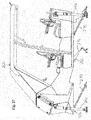
- FIG. 1 through 8 there is illustrated an embodiment of the present invention comprising a marine platform 200 and an associated double-wishbone roll-attenuation suspension system, generally referenced by numeral 300, mounted to a deck 204.
- the embodiment is shown with the marine platform 200 in a no-load at-rest position.
- the embodiment is shown with the marine platform 200 in a compressed bottom position
- the embodiment is shown with the marine platform 200 rolled to starboard relative to the deck 204.
- the double-wishbone roll-attenuation suspension system 300 includes four struts 206, a forward wishbone 302, an aft wishbone 304, and a roll-attenuation assembly 220.
- each of the forward wishbone 302 and aft wishbone 304 is pivotally attached to the deck 204 with two wishbone deck brackets 310 and is pivotally attached to the marine platform 200 with a wishbone platform bracket 312.
- the heim joint 314 at the connection between each wishbone platform bracket 312 and the respective forward wishbone 302 and aft wishbone 304 permits some lateral pivotal movement so as to accommodate rolling of the marine platform 200 relative to the deck 204 when in use.
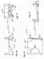
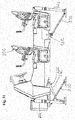
- FIG. 9 through 13 there is illustrated an embodiment of the present invention comprising a marine platform 200 and an associated single-wishbone panhard roll-attenuation suspension system, generally referenced by numeral 350, mounted to a deck 204.
- the embodiment is shown with the marine platform 200 in a no-load at-rest position.
- the embodiment is shown with the marine platform 200 in a compressed bottom position.
- the single-wishbone panhard roll-attenuation suspension system 350 includes four struts 206, an aft wishbone 304, a roll-attenuation assembly 220 and a panhard assembly 360.
- the aft wishbone 214 is configured and mounted as described above.
- the panhard assembly 360 comprises a panhard rod 362, a panhard deck mount 364 and a panhard platform mount 366.
- the proximal end of the panhard rod 362 is pivotally mounted to the deck 204 with the panhard deck mount 364.
- the distal end of the panhard rod 362 is pivotally mounted to the marine platform 200 with the panhard platform mount 366.
- the panhard assembly 360 is positioned in the vicinity of the forward end of marine platform 200.
- the panhard assembly 360 prevents more than minimal lateral movement of marine platform 200 relative to deck 204.
- panhard rod 360 induces a slight lateral movement of marine platform 200 during vertical movement of marine platform 200. This slight lateral movement of marine platform 200 relative to deck 204 is accommodated generally by the various connections between the components of embodiment being configured to permit some relative lateral movement.
- FIG. 14 there is illustrated an embodiment of the present invention comprising a control module 400, and a double-wishbone suspension system, generally referenced by numeral 410, mounted to a deck 204.
- the control module 400 comprises two seats 420, a helm/control station 422, two foot rests 424 (one on the port side and the other on the starboard side; only one is visible in the drawing) and two foot openings 426 (again, one on the port side and the other on the starboard side; only one is visible in the drawing).
- the foot openings 426 permit users to selectively stand on the deck 204 or sit on the seats 420 while controlling the vessel or while being partially sheltered from spray by the control module 400.
- the double-wishbone suspension system 410 includes four struts 206, a forward wishbone 302 and an aft wishbone 304.
- FIG. 15 there is illustrated an embodiment of the present invention comprising a marine platform 200 and an associated single-wishbone Watt's linkage roll-attenuation suspension system, generally referenced by numeral 450, mounted to a deck 204.
- the embodiment is shown with the marine platform 200 in a no-load at-rest position.
- the single-wishbone Watt's linkage roll-attenuation suspension system 450 includes four struts 206, an aft wishbone 214, a roll-attenuation assembly 222 and a Watt's linkage 460.
- the Watt's linkage 460 embodiment shown in the drawings comprises a Watt's link 462 rotatably mounted to the marine platform 200; a starboard Watt's rod 464 attached at one end to the Watt's link 462 and attached at the other end to the deck 204 via a starboard Watt's rod deck mount 466; and a port Watt's rod 468 attached at one end to the Watt's link 462 (opposite the location of attachment of the starboard Watt's rod 464) and attached at the other end to the deck 204 via a port Watt's rod deck mount 470.
- the Watt's linkage 460 permits vertical movement of the marine platform 200 relative to the deck 204, with minimal lateral movement of the marine platform 200 relative to the deck 204.
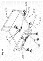
- FIG. 16 there is illustrated an embodiment of the present invention comprising a marine platform 200 and an associated double two-spar roll-attenuation suspension system, generally referenced by numeral 500, mounted to a deck 204.
- the embodiment is shown with the marine platform 200 in a no-load at-rest position.
- the double two-spar roll-attenuation suspension system 500 includes four struts 206, a roll-attenuation assembly 220 and four spars 270.
- the spars 270 are arranged in two pairs, a forward pair and an aft pair, with each pair in the shape of a V, with the base of the V attached to the marine platform 200 and the top of the V attached to the deck 204.
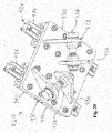
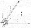
- FIG. 20 to 31 there are shown movement-accommodating spar brackets which permit relative fore and aft movement as between the spars 270 (or forward wishbone 302 or aft wishbone 304) and marine platform 200, or the deck 204, that the movement-accommodating spar bracket is interconnecting.
- the movement-accommodating spar bracket embodiments illustrated in the drawings are a sliding spar bracket 930 and pivoting spar bracket 950, which are configured for interconnecting two spars 270 to a marine platform 200.
- the sliding spar bracket 930 comprises a track assembly 922 and a slide assembly 924.
- the track assembly 922 comprises two spaced-apart parallel tracks 926 having a general "T" configuration.
- the track assembly 922 may also include a track mount 928, being, in the embodiments shown in the drawings, a plate suitable for maintaining the relative orientation of the tracks 926 during use and for affixing to the marine platform 200.
- the tracks 926 may be affixed directly to the marine platform 200.
- the slide assembly 924 comprises a slide assembly body 930, two spar connectors 932 on the lower side of the slide assembly body 930 and two spaced apart aligned car assemblies 934 on the upper side of the slide assembly body 930.
- Each spar connector 932 comprises two parallel projecting tangs 936 configured (including each having a hole therethrough) for receiving the heim joint 314 of a respective spar 270 and securing same with a heim joint fastener 938.
- the spar connectors 932 are angled relative to each other so as to be aligned with a pair of spars 270 oriented in the shape of a V, with the base of the V attached to the spar connectors 932 and the top of the V attached to the deck 204.
- Each car assembly 934 comprises one or more aligned cars 940 configured for slidable engagement with a respective track 926.
- the slide assembly 924 and track assembly 922 are constrained to undergoing relative reciprocating linear movement.
- the slide assembly body 930 is preferably metal (preferably stainless steel plate) and the tangs 936 are preferably welded to the slide assembly body 930, the face of the slide assembly body 930 to which the tracks 926 are affixed, is preferably machined after the tangs 936 are attached to remove any distortion caused by the welding.
- the tracks 926 and cars 940 are preferably corrosion resistant and low friction without lubrication.
- the tracks 926 are preferably anodized aluminum T- rail.
- the cars 940 preferably comprise anodized aluminum bodies with low-friction plastic sliding elements.
- IGUS GmbH and IGUS Inc. are suitable for use as cars 940 and tracks 926, namely DryLin® T - profile rail series, specifically car part no. TW-01-25 and rail part no. TS-01-25 (the car is 6063-T6 Aluminum and clear anodized, and the rail is 6063-T6 Aluminum and hard anodized).
- the IGUS GmbH and IGUS Inc. cars in include a sliding element made from iglide® J material and the sliding elements are adjustable with stainless steel screws.
- the pivoting spar bracket 950 comprises a pivot block 952, a pivot cavity 954 and pivot pin assembly 956.
- the pivot block 952 includes two spar connectors 932 oriented in the same manner as the spar connectors 932 of the sliding spar bracket 920.
- the pivot block 952 includes a pivot block bore 958.
- the pivot cavity 954 includes a recess for receiving the pivot block 952 and two pivot cavity holes 960.
- the pivot cavity 954 may be a separate component affixed to the marine platform 200 or may be integral to the marine platform 200.
- the pivot pin assembly 956 includes a pivot bolt 962, pivot nut 964, pivot washer 966, two pivot sleeves 968 and a pivot bushing 970.
- the pivoting spar bracket 950 is assembled by: inserting a pivot sleeve 968 into each end of the pivot block bore 958; inserting the pivot bushing 970 into the pivot sleeves 968; positioning the pivot block 952 within the pivot cavity 954 so as to bring the pivot block bore 958 into alignment with the pivot cavity holes 960; inserting the pivot bolt 962 therethrough; and securing the pivot bolt 962 with the pivot nut 964 and pivot washer 966.
- iglide® J material provided by IGUS GmbH and IGUS Inc. is suitable for use as pivot bushing 970, for example bushing part no: JFI-2428-24.
- Double two-spar roll-attenuation embodiments of the present invention with movement-accommodating spar brackets are shown in the drawings.
- Figures 26 and 27 show a double two-spar roll-attenuation embodiment of the present invention with movement-accommodating spar brackets wherein the forward spars 270 are interconnected to the marine platform 200 via a sliding spar bracket 920 and the torsion spring 242 is attached to the marine platform 200 roughly in the middle of the fore and aft extent of the marine platform and with the adjustable torsion arms 246 extending aft from the torsion spring 242.
- Figures 28 and 29 show a double two-spar roll-attenuation embodiment of the present invention with movement-accommodating spar brackets wherein the aft spars 270 are interconnected to the marine platform 200 via a sliding spar bracket 920 and the torsion spring 242 is attached to the marine platform 200 toward the forward end of the marine platform and with the adjustable torsion arms 246 extending forward from the torsion spring 242.
- Figures 30 and 31 show a double two-spar roll-attenuation embodiment of the present invention with movement-accommodating spar brackets wherein the aft spars 270 are interconnected to the marine platform 200 via a pivoting spar bracket 950 and the torsion spring 242 is attached to the marine platform 200 toward the forward end of the marine platform and with the adjustable torsion arms 246 extending forward from the torsion spring 242.
- movement-accommodating spar brackets permit relative differential vertical movement as between the forward and aft portions of the marine platform 200, which improves suspension performance in terms of response to pitch.
- the sliding spar bracket 920 and pivoting spar bracket 950 are preferably configured to accommodate the maximum permitted differential movement as between the forward and aft portions of the marine platform 200, in terms of the simultaneous maximum compression of the forward struts 206 and maximum extension of the aft struts 206, or the simultaneous maximum extension of the forward struts 206 and maximum compression of the aft struts 206.
- Similar permitted relative differential vertical movement as between the forward and aft portions of the marine platform 200 could be provided by interconnecting the two spars 270 to the deck 204 with a movement accommodating mounting (not shown), although it is understood that it is simpler and thus preferable to have a single movement accommodating component where the spars 270 converge (i.e., as described above).
Landscapes
- Chemical & Material Sciences (AREA)
- Engineering & Computer Science (AREA)
- Combustion & Propulsion (AREA)
- Mechanical Engineering (AREA)
- Ocean & Marine Engineering (AREA)
- Vibration Prevention Devices (AREA)
- Vehicle Body Suspensions (AREA)
Claims (10)
- Aufhängungssystem für eine aufgehängte Meeresplattform (200) auf einem Hochgeschwindigkeits-Wasserfahrzeug, das eine übliche Bewegungsrichtung aufweist, wobei das Aufhängungssystem Folgendes umfasst:eine Stoßdämpfungsanordnung zum elastischen Aufhängen einer Meeresplattform (200) in Bezug auf ein Fahrzeug, wobei die Stoßdämpfungsanordnung tendenziell bewirkt, dass die Meeresplattform (200) in einer oberen Ruheposition verbleibt und zur Ruheposition zurückkehrt, wenn eine Kraft, die bewirkt, dass die Meeresplattform (200) sich im Wesentlichen vertikal in Richtung einer unteren Position bewegt, aussetzt;zwei Holmanordnungen, wobei eine der Holmanordnungen vor der anderen Holmanordnung angeordnet ist und jede Holmanordnung einen ersten Holm (270) und einen zweiten Holm (270) umfasst, wobei jeder Holm an einem proximalen Ende schwenkbar auf dem Fahrzeug befestigt ist und an einem distalen Ende schwenkbar auf der Meeresplattform (200) befestigt ist, wobei:die proximalen Enden hinter den distalen Enden liegen; unddie proximalen Enden der Holme (270) in Querrichtung voneinander in einem größeren Abstand beabstandet sind als die distalen Enden der Holme (270) in Querrichtung voneinander beabstandet sind;dadurch gekennzeichnet, dassdie Anbringung von einer der Holmanordnungen an dem Fahrzeug eine relative Vorwärts- und Rückwärtsbewegung zwischen dem Fahrzeug und den proximalen Enden der Holme (270) dieser einen der Holmanordnungen ermöglicht; oder dassdie Anbringung von einer der Holmanordnungen an der Meeresplattform (200) eine relative Vorwärts- und Rückwärtsbewegung zwischen der Meeresplattform (200) und den distalen Enden der Holme (270) dieser einen der Holmanordnungen ermöglicht.
- Aufhängungssystem nach Anspruch 1, wobei die Anbringung der einen der Holmanordnungen an der Meeresplattform (200) eine relative Vorwärts- und Rückwärtsbewegung zwischen der Meeresplattform (200) und den distalen Enden der Holme (270) dieser einen der Holmanordnungen ermöglicht.
- Aufhängungssystem nach Anspruch 2, wobei die relative Vorwärts- und Rückwärtsbewegung zwischen der Meeresplattform (200) und den distalen Enden der Holme (270) dieser einen der Holmanordnungen linear ist.
- Aufhängungssystem nach Anspruch 3, wobei die relative Vorwärts- und Rückwärtsbewegung zwischen der Meeresplattform (200) und den distalen Enden der Holme (270) dieser einen der Holmanordnungen durch eine Schienen- und Wagenanordnung (920) bereitgestellt ist.
- Aufhängungssystem nach Anspruch 2, wobei die relative Vorwärts- und Rückwärtsbewegung zwischen der Meeresplattform (200) und den distalen Enden der Holme dieser einen der Holmanordnungen bogenförmig ist.
- Aufhängungssystem nach Anspruch 5, wobei die relative Vorwärts- und Rückwärtsbewegung zwischen der Meeresplattform (200) und den distalen Enden der Holme dieser einen der Holmanordnungen durch eine Schwenkanordnung (950) bereitgestellt ist.
- Aufhängungssystem nach Anspruch 1, das ferner eine Rolldämpfungsanordnung (220), die zwischen der Meeresplattform (200) und dem Fahrzeug zwischenverbunden ist, umfasst.
- Aufhängungssystem nach Anspruch 7, wobei die Rolldämpfungsanordnung (220) einen Torsionsstab (240) umfasst, der angebracht ist, um sich in Querrichtung zu erstrecken, wobei der Torsionsstab (240) eine Torsionsfeder (242) umfasst, die an jedem Ende einen Arm (244) aufweist, der sich von der Torsionsfeder (242) aus seitwärts erstreckt, wobei die Torsionsfeder (242) auf einem aus der Meeresplattform (200) und dem Fahrzeug befestigt ist und die Arme (244) mit dem anderen aus der Meeresplattform (200) und dem Fahrzeug zwischenverbunden sind.
- Aufhängungssystem nach Anspruch 1, wobei in einer der Holmanordnungen (302, 304) der erste und der zweite Holm in der Nähe ihrer distalen Enden aneinander fixiert sind und die Schwenkanbringung ihrer distalen Enden auf der Meeresplattform (200) durch eine gemeinsame Schwenkanbringung (312) erfolgt.
- Aufhängungssystem nach Anspruch 1, wobei die Stoßdämpfungsanordnung vier Stoßdämpfungsfederbeine (206) umfasst, die jeweils zwischen der Meeresplattform (200) und dem Fahrzeug zwischenverbunden sind.
Applications Claiming Priority (2)
| Application Number | Priority Date | Filing Date | Title |
|---|---|---|---|
| US14/639,091 US9422039B2 (en) | 2011-03-30 | 2015-03-04 | Suspended marine platform |
| PCT/CA2016/050181 WO2016138578A1 (en) | 2015-03-04 | 2016-02-23 | Suspended marine platform |
Publications (3)
| Publication Number | Publication Date |
|---|---|
| EP3265378A1 EP3265378A1 (de) | 2018-01-10 |
| EP3265378A4 EP3265378A4 (de) | 2018-10-24 |
| EP3265378B1 true EP3265378B1 (de) | 2020-04-08 |
Family
ID=56849149
Family Applications (1)
| Application Number | Title | Priority Date | Filing Date |
|---|---|---|---|
| EP16758394.7A Active EP3265378B1 (de) | 2015-03-04 | 2016-02-23 | Hängende meeresplattform |
Country Status (4)
| Country | Link |
|---|---|
| EP (1) | EP3265378B1 (de) |
| AU (1) | AU2016228135B2 (de) |
| CA (1) | CA2975911C (de) |
| WO (1) | WO2016138578A1 (de) |
Families Citing this family (2)
| Publication number | Priority date | Publication date | Assignee | Title |
|---|---|---|---|---|
| US11124272B2 (en) * | 2019-11-11 | 2021-09-21 | Steering Solutions Ip Holding Corporation | System and method for vibration cancellation |
| CN114352706B (zh) * | 2021-11-26 | 2024-04-26 | 武汉船用机械有限责任公司 | 海洋平台齿轮箱安装方法 |
Family Cites Families (7)
| Publication number | Priority date | Publication date | Assignee | Title |
|---|---|---|---|---|
| US3237906A (en) * | 1964-01-29 | 1966-03-01 | American Metal Prod | Snubbing load applying spring |
| US5542371A (en) * | 1993-05-04 | 1996-08-06 | Bombardier Inc. | Watercraft seat suspension |
| US6237889B1 (en) * | 1998-07-16 | 2001-05-29 | Eric Bischoff | Seat suspension assembly |
| US6786172B1 (en) * | 2003-09-08 | 2004-09-07 | Leonard Loffler | Shock absorbing boat |
| WO2005025980A1 (de) * | 2003-09-17 | 2005-03-24 | Supraventures Ag | Wasserfahrzeug mit zwei aufeinandergestappelten schwimmkörpern |
| WO2009127070A1 (en) * | 2008-04-16 | 2009-10-22 | Professional Components Ltd. | Passenger module suspension system |
| CA2831150C (en) * | 2011-03-30 | 2019-05-21 | David Alvin SMITH | Suspended marine platform |
-
2016
- 2016-02-23 EP EP16758394.7A patent/EP3265378B1/de active Active
- 2016-02-23 AU AU2016228135A patent/AU2016228135B2/en active Active
- 2016-02-23 CA CA2975911A patent/CA2975911C/en active Active
- 2016-02-23 WO PCT/CA2016/050181 patent/WO2016138578A1/en not_active Ceased
Non-Patent Citations (1)
| Title |
|---|
| None * |
Also Published As
| Publication number | Publication date |
|---|---|
| EP3265378A1 (de) | 2018-01-10 |
| CA2975911C (en) | 2021-07-06 |
| EP3265378A4 (de) | 2018-10-24 |
| AU2016228135A1 (en) | 2017-10-12 |
| WO2016138578A1 (en) | 2016-09-09 |
| CA2975911A1 (en) | 2016-09-09 |
| AU2016228135B2 (en) | 2019-11-07 |
Similar Documents
| Publication | Publication Date | Title |
|---|---|---|
| EP2817213B1 (de) | Boot mit einem aktiven aufhängungssystem | |
| US8118287B2 (en) | Shock-mitigating apparatus for seats and other objects | |
| CA2721613C (en) | Passenger module suspension system | |
| JP6886721B2 (ja) | 多胴型船舶用のマルチリンクサスペンション | |
| US9422039B2 (en) | Suspended marine platform | |
| CN114198455A (zh) | 安装于运载设备的自平衡减振系统 | |
| JP2019507054A5 (de) | ||
| EP2691292B1 (de) | Hängende meeresplattform | |
| CA2975911C (en) | Suspended marine platform | |
| EP1590233B1 (de) | Aktives deckaufhängungssystem | |
| US7293830B2 (en) | Shock-mitigating bolster | |
| US9840310B2 (en) | Marine suspension system | |
| US8261684B2 (en) | Shock absorbing cockpits | |
| WO1992012892A1 (en) | Shock absorbing mounting system for high speed watercraft seat | |
| US7434525B2 (en) | Suspension system for a boat | |
| EP2899063A1 (de) | Selbstnivellierende Sitzplattform | |
| JPH05505987A (ja) | 高速船舶用座席の衝撃吸収座席取付け装置 | |
| HK40016217A (en) | Boat with active suspension system | |
| KR20080089393A (ko) | 거친 수상조건에 적합한 고속 선박 | |
| JPH08510190A (ja) | 水上乗り物 |
Legal Events
| Date | Code | Title | Description |
|---|---|---|---|
| STAA | Information on the status of an ep patent application or granted ep patent |
Free format text: STATUS: THE INTERNATIONAL PUBLICATION HAS BEEN MADE |
|
| PUAI | Public reference made under article 153(3) epc to a published international application that has entered the european phase |
Free format text: ORIGINAL CODE: 0009012 |
|
| STAA | Information on the status of an ep patent application or granted ep patent |
Free format text: STATUS: REQUEST FOR EXAMINATION WAS MADE |
|
| 17P | Request for examination filed |
Effective date: 20171003 |
|
| AK | Designated contracting states |
Kind code of ref document: A1 Designated state(s): AL AT BE BG CH CY CZ DE DK EE ES FI FR GB GR HR HU IE IS IT LI LT LU LV MC MK MT NL NO PL PT RO RS SE SI SK SM TR |
|
| AX | Request for extension of the european patent |
Extension state: BA ME |
|
| DAV | Request for validation of the european patent (deleted) | ||
| DAX | Request for extension of the european patent (deleted) | ||
| A4 | Supplementary search report drawn up and despatched |
Effective date: 20180926 |
|
| RIC1 | Information provided on ipc code assigned before grant |
Ipc: B63B 17/00 20060101ALI20180920BHEP Ipc: B63B 39/00 20060101AFI20180920BHEP |
|
| GRAP | Despatch of communication of intention to grant a patent |
Free format text: ORIGINAL CODE: EPIDOSNIGR1 |
|
| STAA | Information on the status of an ep patent application or granted ep patent |
Free format text: STATUS: GRANT OF PATENT IS INTENDED |
|
| INTG | Intention to grant announced |
Effective date: 20191016 |
|
| GRAS | Grant fee paid |
Free format text: ORIGINAL CODE: EPIDOSNIGR3 |
|
| GRAA | (expected) grant |
Free format text: ORIGINAL CODE: 0009210 |
|
| STAA | Information on the status of an ep patent application or granted ep patent |
Free format text: STATUS: THE PATENT HAS BEEN GRANTED |
|
| AK | Designated contracting states |
Kind code of ref document: B1 Designated state(s): AL AT BE BG CH CY CZ DE DK EE ES FI FR GB GR HR HU IE IS IT LI LT LU LV MC MK MT NL NO PL PT RO RS SE SI SK SM TR |
|
| REG | Reference to a national code |
Ref country code: AT Ref legal event code: REF Ref document number: 1254040 Country of ref document: AT Kind code of ref document: T Effective date: 20200415 Ref country code: CH Ref legal event code: EP |
|
| REG | Reference to a national code |
Ref country code: DE Ref legal event code: R096 Ref document number: 602016033640 Country of ref document: DE |
|
| REG | Reference to a national code |
Ref country code: IE Ref legal event code: FG4D |
|
| REG | Reference to a national code |
Ref country code: NL Ref legal event code: MP Effective date: 20200408 |
|
| REG | Reference to a national code |
Ref country code: LT Ref legal event code: MG4D |
|
| PG25 | Lapsed in a contracting state [announced via postgrant information from national office to epo] |
Ref country code: FI Free format text: LAPSE BECAUSE OF FAILURE TO SUBMIT A TRANSLATION OF THE DESCRIPTION OR TO PAY THE FEE WITHIN THE PRESCRIBED TIME-LIMIT Effective date: 20200408 Ref country code: IS Free format text: LAPSE BECAUSE OF FAILURE TO SUBMIT A TRANSLATION OF THE DESCRIPTION OR TO PAY THE FEE WITHIN THE PRESCRIBED TIME-LIMIT Effective date: 20200808 Ref country code: SE Free format text: LAPSE BECAUSE OF FAILURE TO SUBMIT A TRANSLATION OF THE DESCRIPTION OR TO PAY THE FEE WITHIN THE PRESCRIBED TIME-LIMIT Effective date: 20200408 Ref country code: LT Free format text: LAPSE BECAUSE OF FAILURE TO SUBMIT A TRANSLATION OF THE DESCRIPTION OR TO PAY THE FEE WITHIN THE PRESCRIBED TIME-LIMIT Effective date: 20200408 Ref country code: PT Free format text: LAPSE BECAUSE OF FAILURE TO SUBMIT A TRANSLATION OF THE DESCRIPTION OR TO PAY THE FEE WITHIN THE PRESCRIBED TIME-LIMIT Effective date: 20200817 Ref country code: NL Free format text: LAPSE BECAUSE OF FAILURE TO SUBMIT A TRANSLATION OF THE DESCRIPTION OR TO PAY THE FEE WITHIN THE PRESCRIBED TIME-LIMIT Effective date: 20200408 Ref country code: GR Free format text: LAPSE BECAUSE OF FAILURE TO SUBMIT A TRANSLATION OF THE DESCRIPTION OR TO PAY THE FEE WITHIN THE PRESCRIBED TIME-LIMIT Effective date: 20200709 Ref country code: NO Free format text: LAPSE BECAUSE OF FAILURE TO SUBMIT A TRANSLATION OF THE DESCRIPTION OR TO PAY THE FEE WITHIN THE PRESCRIBED TIME-LIMIT Effective date: 20200708 |
|
| REG | Reference to a national code |
Ref country code: AT Ref legal event code: MK05 Ref document number: 1254040 Country of ref document: AT Kind code of ref document: T Effective date: 20200408 |
|
| PG25 | Lapsed in a contracting state [announced via postgrant information from national office to epo] |
Ref country code: LV Free format text: LAPSE BECAUSE OF FAILURE TO SUBMIT A TRANSLATION OF THE DESCRIPTION OR TO PAY THE FEE WITHIN THE PRESCRIBED TIME-LIMIT Effective date: 20200408 Ref country code: BG Free format text: LAPSE BECAUSE OF FAILURE TO SUBMIT A TRANSLATION OF THE DESCRIPTION OR TO PAY THE FEE WITHIN THE PRESCRIBED TIME-LIMIT Effective date: 20200708 Ref country code: RS Free format text: LAPSE BECAUSE OF FAILURE TO SUBMIT A TRANSLATION OF THE DESCRIPTION OR TO PAY THE FEE WITHIN THE PRESCRIBED TIME-LIMIT Effective date: 20200408 Ref country code: HR Free format text: LAPSE BECAUSE OF FAILURE TO SUBMIT A TRANSLATION OF THE DESCRIPTION OR TO PAY THE FEE WITHIN THE PRESCRIBED TIME-LIMIT Effective date: 20200408 |
|
| PG25 | Lapsed in a contracting state [announced via postgrant information from national office to epo] |
Ref country code: AL Free format text: LAPSE BECAUSE OF FAILURE TO SUBMIT A TRANSLATION OF THE DESCRIPTION OR TO PAY THE FEE WITHIN THE PRESCRIBED TIME-LIMIT Effective date: 20200408 |
|
| REG | Reference to a national code |
Ref country code: DE Ref legal event code: R097 Ref document number: 602016033640 Country of ref document: DE |
|
| PG25 | Lapsed in a contracting state [announced via postgrant information from national office to epo] |
Ref country code: DK Free format text: LAPSE BECAUSE OF FAILURE TO SUBMIT A TRANSLATION OF THE DESCRIPTION OR TO PAY THE FEE WITHIN THE PRESCRIBED TIME-LIMIT Effective date: 20200408 Ref country code: AT Free format text: LAPSE BECAUSE OF FAILURE TO SUBMIT A TRANSLATION OF THE DESCRIPTION OR TO PAY THE FEE WITHIN THE PRESCRIBED TIME-LIMIT Effective date: 20200408 Ref country code: IT Free format text: LAPSE BECAUSE OF FAILURE TO SUBMIT A TRANSLATION OF THE DESCRIPTION OR TO PAY THE FEE WITHIN THE PRESCRIBED TIME-LIMIT Effective date: 20200408 Ref country code: SM Free format text: LAPSE BECAUSE OF FAILURE TO SUBMIT A TRANSLATION OF THE DESCRIPTION OR TO PAY THE FEE WITHIN THE PRESCRIBED TIME-LIMIT Effective date: 20200408 Ref country code: EE Free format text: LAPSE BECAUSE OF FAILURE TO SUBMIT A TRANSLATION OF THE DESCRIPTION OR TO PAY THE FEE WITHIN THE PRESCRIBED TIME-LIMIT Effective date: 20200408 Ref country code: ES Free format text: LAPSE BECAUSE OF FAILURE TO SUBMIT A TRANSLATION OF THE DESCRIPTION OR TO PAY THE FEE WITHIN THE PRESCRIBED TIME-LIMIT Effective date: 20200408 Ref country code: CZ Free format text: LAPSE BECAUSE OF FAILURE TO SUBMIT A TRANSLATION OF THE DESCRIPTION OR TO PAY THE FEE WITHIN THE PRESCRIBED TIME-LIMIT Effective date: 20200408 Ref country code: RO Free format text: LAPSE BECAUSE OF FAILURE TO SUBMIT A TRANSLATION OF THE DESCRIPTION OR TO PAY THE FEE WITHIN THE PRESCRIBED TIME-LIMIT Effective date: 20200408 |
|
| PLBE | No opposition filed within time limit |
Free format text: ORIGINAL CODE: 0009261 |
|
| STAA | Information on the status of an ep patent application or granted ep patent |
Free format text: STATUS: NO OPPOSITION FILED WITHIN TIME LIMIT |
|
| PG25 | Lapsed in a contracting state [announced via postgrant information from national office to epo] |
Ref country code: PL Free format text: LAPSE BECAUSE OF FAILURE TO SUBMIT A TRANSLATION OF THE DESCRIPTION OR TO PAY THE FEE WITHIN THE PRESCRIBED TIME-LIMIT Effective date: 20200408 Ref country code: SK Free format text: LAPSE BECAUSE OF FAILURE TO SUBMIT A TRANSLATION OF THE DESCRIPTION OR TO PAY THE FEE WITHIN THE PRESCRIBED TIME-LIMIT Effective date: 20200408 |
|
| 26N | No opposition filed |
Effective date: 20210112 |
|
| PG25 | Lapsed in a contracting state [announced via postgrant information from national office to epo] |
Ref country code: SI Free format text: LAPSE BECAUSE OF FAILURE TO SUBMIT A TRANSLATION OF THE DESCRIPTION OR TO PAY THE FEE WITHIN THE PRESCRIBED TIME-LIMIT Effective date: 20200408 |
|
| PG25 | Lapsed in a contracting state [announced via postgrant information from national office to epo] |
Ref country code: MC Free format text: LAPSE BECAUSE OF FAILURE TO SUBMIT A TRANSLATION OF THE DESCRIPTION OR TO PAY THE FEE WITHIN THE PRESCRIBED TIME-LIMIT Effective date: 20200408 |
|
| REG | Reference to a national code |
Ref country code: BE Ref legal event code: MM Effective date: 20210228 |
|
| PG25 | Lapsed in a contracting state [announced via postgrant information from national office to epo] |
Ref country code: LU Free format text: LAPSE BECAUSE OF NON-PAYMENT OF DUE FEES Effective date: 20210223 Ref country code: LI Free format text: LAPSE BECAUSE OF NON-PAYMENT OF DUE FEES Effective date: 20210228 Ref country code: CH Free format text: LAPSE BECAUSE OF NON-PAYMENT OF DUE FEES Effective date: 20210228 |
|
| PG25 | Lapsed in a contracting state [announced via postgrant information from national office to epo] |
Ref country code: IE Free format text: LAPSE BECAUSE OF NON-PAYMENT OF DUE FEES Effective date: 20210223 |
|
| PG25 | Lapsed in a contracting state [announced via postgrant information from national office to epo] |
Ref country code: BE Free format text: LAPSE BECAUSE OF NON-PAYMENT OF DUE FEES Effective date: 20210228 |
|
| PG25 | Lapsed in a contracting state [announced via postgrant information from national office to epo] |
Ref country code: CY Free format text: LAPSE BECAUSE OF FAILURE TO SUBMIT A TRANSLATION OF THE DESCRIPTION OR TO PAY THE FEE WITHIN THE PRESCRIBED TIME-LIMIT Effective date: 20200408 |
|
| PG25 | Lapsed in a contracting state [announced via postgrant information from national office to epo] |
Ref country code: HU Free format text: LAPSE BECAUSE OF FAILURE TO SUBMIT A TRANSLATION OF THE DESCRIPTION OR TO PAY THE FEE WITHIN THE PRESCRIBED TIME-LIMIT; INVALID AB INITIO Effective date: 20160223 |
|
| PG25 | Lapsed in a contracting state [announced via postgrant information from national office to epo] |
Ref country code: MK Free format text: LAPSE BECAUSE OF FAILURE TO SUBMIT A TRANSLATION OF THE DESCRIPTION OR TO PAY THE FEE WITHIN THE PRESCRIBED TIME-LIMIT Effective date: 20200408 |
|
| PG25 | Lapsed in a contracting state [announced via postgrant information from national office to epo] |
Ref country code: TR Free format text: LAPSE BECAUSE OF FAILURE TO SUBMIT A TRANSLATION OF THE DESCRIPTION OR TO PAY THE FEE WITHIN THE PRESCRIBED TIME-LIMIT Effective date: 20200408 |
|
| PG25 | Lapsed in a contracting state [announced via postgrant information from national office to epo] |
Ref country code: MT Free format text: LAPSE BECAUSE OF FAILURE TO SUBMIT A TRANSLATION OF THE DESCRIPTION OR TO PAY THE FEE WITHIN THE PRESCRIBED TIME-LIMIT Effective date: 20200408 |
|
| PGFP | Annual fee paid to national office [announced via postgrant information from national office to epo] |
Ref country code: GB Payment date: 20260203 Year of fee payment: 11 |
|
| PGFP | Annual fee paid to national office [announced via postgrant information from national office to epo] |
Ref country code: DE Payment date: 20260211 Year of fee payment: 11 |
|
| PGFP | Annual fee paid to national office [announced via postgrant information from national office to epo] |
Ref country code: FR Payment date: 20260203 Year of fee payment: 11 |