EP3265302B1 - Radial press - Google Patents
Radial press Download PDFInfo
- Publication number
- EP3265302B1 EP3265302B1 EP16707121.6A EP16707121A EP3265302B1 EP 3265302 B1 EP3265302 B1 EP 3265302B1 EP 16707121 A EP16707121 A EP 16707121A EP 3265302 B1 EP3265302 B1 EP 3265302B1
- Authority
- EP
- European Patent Office
- Prior art keywords
- pressing
- press according
- pressing jaw
- radial press
- jaw heads
- Prior art date
- Legal status (The legal status is an assumption and is not a legal conclusion. Google has not performed a legal analysis and makes no representation as to the accuracy of the status listed.)
- Active
Links
- 238000003825 pressing Methods 0.000 claims description 98
- 238000004519 manufacturing process Methods 0.000 description 4
- 238000002788 crimping Methods 0.000 description 3
- 239000000463 material Substances 0.000 description 3
- 230000002349 favourable effect Effects 0.000 description 2
- TWFZGCMQGLPBSX-UHFFFAOYSA-N carbendazim Chemical compound C1=CC=C2NC(NC(=O)OC)=NC2=C1 TWFZGCMQGLPBSX-UHFFFAOYSA-N 0.000 description 1
- 239000002131 composite material Substances 0.000 description 1
- 230000006835 compression Effects 0.000 description 1
- 238000007906 compression Methods 0.000 description 1
- 230000000694 effects Effects 0.000 description 1
- 238000000034 method Methods 0.000 description 1
- 238000000926 separation method Methods 0.000 description 1
- 239000007787 solid Substances 0.000 description 1
- 238000009827 uniform distribution Methods 0.000 description 1
Images


Classifications
-
- B—PERFORMING OPERATIONS; TRANSPORTING
- B30—PRESSES
- B30B—PRESSES IN GENERAL
- B30B11/00—Presses specially adapted for forming shaped articles from material in particulate or plastic state, e.g. briquetting presses, tabletting presses
- B30B11/007—Presses specially adapted for forming shaped articles from material in particulate or plastic state, e.g. briquetting presses, tabletting presses using a plurality of pressing members working in different directions
-
- B—PERFORMING OPERATIONS; TRANSPORTING
- B21—MECHANICAL METAL-WORKING WITHOUT ESSENTIALLY REMOVING MATERIAL; PUNCHING METAL
- B21D—WORKING OR PROCESSING OF SHEET METAL OR METAL TUBES, RODS OR PROFILES WITHOUT ESSENTIALLY REMOVING MATERIAL; PUNCHING METAL
- B21D39/00—Application of procedures in order to connect objects or parts, e.g. coating with sheet metal otherwise than by plating; Tube expanders
- B21D39/04—Application of procedures in order to connect objects or parts, e.g. coating with sheet metal otherwise than by plating; Tube expanders of tubes with tubes; of tubes with rods
- B21D39/048—Application of procedures in order to connect objects or parts, e.g. coating with sheet metal otherwise than by plating; Tube expanders of tubes with tubes; of tubes with rods using presses for radially crimping tubular elements
-
- B—PERFORMING OPERATIONS; TRANSPORTING
- B30—PRESSES
- B30B—PRESSES IN GENERAL
- B30B7/00—Presses characterised by a particular arrangement of the pressing members
- B30B7/04—Presses characterised by a particular arrangement of the pressing members wherein pressing is effected in different directions simultaneously or in turn
Definitions
- the present invention relates to a radial press having a basic structure, a pressing tool accommodated therein and a drive unit, wherein the pressing tool comprises eight base jaws arranged around a press axis, which synchronously radially open and close the pressing tool by means of the drive unit to the press axis These are movable away and on each of which a pressing surface comprehensive press jaw head is interchangeable attachable.
- Radial presses of the above-mentioned type serve, for example, the production of a solid connection between a hydraulic hose and a terminal arranged at this connection fitting by a Radialverpressen (crimping) of the connection fitting, are known in various designs, in particular from the product range of Uniflex Hydraulik GmbH, Karben (Germany) and from the patent literature (cf., for example WO 2012/130360 A1 . EP 239875 A2 . EP 539787 A1 . EP 1252943 A1 and DE 3512241 A1 ). document DE3513129 A1 discloses a radial press according to the preamble of claim 1.
- the number (eight) of the base jaws has been found in practice to be optimal and thus enforced; because in radial presses, which have a smaller number (eg six) of base jaws, the compression of the material of the workpiece over the circumference is too uneven to meet high demands on the quality of the workpiece.
- the distance between adjacent pressing jaw heads in the circumferential direction is so large that, depending on the Properties of the material to be pressed of the workpiece, material can be pressed into the column in question, under which the quality of the finished workpiece suffers even more.
- the replaceable attachable to the base jaws typically substantially wedge-shaped press jaw heads each have a pressing surface according to a circular cylinder segment (1/8 circular cylinder), so that the pressing surfaces together define a substantially circular cylindrical inner surface with maximum closed pressing tool.
- the radial press can be converted with different dimensions to produce workpieces with little effort.
- the different press jaw heads differ in this case by a more or less large radial extent.
- the present invention has set itself the task of expanding the range of applications of known generic radial presses.
- it is important to increase the efficiency of radial presses, namely by the ability to use generic radial presses for the reliable production of such pressed workpieces, which are substantially different from the traditionally differ by means of the radial presses concerned.
- the above object is achieved according to the present invention by at least four press jaw heads are attached to the eight base jaws, which form a limited by six flat forming surfaces cavity in the form of a uniform hexagonal prism with maximum closed pressing tool around the press axis.
- a first preferred embodiment of the present invention is characterized in that ends on at least two of the six planar forming surfaces dividing surfaces, which each form two adjacent pressing jaw heads with each other.
- at least two of the six flat forming surfaces are made up of two Press surface portions of adjacent pressing jaw heads together.
- each second base jaw is equipped with a pressing jaw head and exactly two of the four separating jaws arranged between the four pressing jaw heads, which are preferably at least partially orthogonal to each other, to two Ending diametrically opposite planar forming surfaces.
- the two other parting surfaces preferably end at two diametrically opposite edges between adjacent planar forming surfaces.
- each of the four pressing surfaces (each associated with one pressing jaw head) has two planar pressing surface sections colliding at one edge.
- the pressing surface of each pressing jaw head defines a complete flat forming surface as well as a part of an adjacent flat forming surface. This is very favorable for the demolding of the workpiece after the hexagonal pressing, compared with an approach in which for a hexagonal pressing two half shells (each having three forming surfaces) are used.
- exactly eight pressing jaw heads are provided, so that each base jaw is equipped with a pressing jaw head, wherein the separating faces at least partially enclose each other with a 45 ° angle.
- four of the eight separating surfaces preferably terminate at four, one at a time in pairs diametrically opposed planar forming surfaces, whereas the other four separating surfaces terminate at four pairs diametrically opposite edges between adjacent planar forming surfaces.
- two opposing pressing surfaces form complete forming surfaces.
- Two mutually orthogonally arranged opposing pressing surfaces each comprise two at a 120 ° angle to each other arranged pressing surface sections, which form subregions of adjacent forming surfaces.
- the pressing surfaces of the remaining four pressing jaw heads form part areas each of a flat forming surface.
- Another preferred development of the present invention is characterized in that exactly six pressing jaw heads are provided, wherein the six separating surfaces, which each form two adjacent pressing jaw heads with one another, terminate in the edge regions of the cavity.
- Each press jaw head accordingly has a pressing surface which defines exactly one complete forming surface.
- these two base jaws which are not equipped with a press jaw head, diametrically opposite each other.
- two yokes which in a direction perpendicular to the press axis drive direction relative
- the two base jaws which are not equipped with press-jaw heads, are particularly preferably opposite each other in a plane perpendicular to the drive direction. It is advantageous if supported at maximum closed pressing tool on the two base jaws, which are not equipped with pressing jaw heads, two press jaw heads.
- yet another preferred development of the present invention is characterized in that mutually corresponding centering means are provided on at least two adjacent pressing jaw heads, which guide the two respective pressing jaw heads - and thus the respective pressing jaws in total.
- Such centering can in particular Include interlocking pins or bolts and holes.
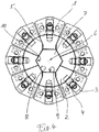
- Fig. 1 To Fig. 1 are the eight (each extending over a wedge angle of 45 °) base jaws 1 of the radial press so equipped with a total of four pressing jaw heads 2 that on each second base jaw 1 - by means of the respectively associated, engaging in a receptacle 3 of the respective base jaw 1 locking pin 4 - a press jaw head 2 is mounted.
- each pressing jaw head 2 there is in each case a separating surface 5. At least radially on the outside, in each case two adjacent separating surfaces 5 enclose an angle of 90 ° with one another.
- each pressing jaw head 2 (approximately 90 °) extends radially outward over an approximately twice as large angular range as the base jaw 1 to which it is attached.
- Each press jaw head 2 is thus in front of the base jaw 1, to which it is fixed, on both sides and extends in this way in front of the two adjacent base jaws 1 (each about half thereof).
- the four press jaw heads 2 circumscribe a cavity 7 in the form of a uniform hexagonal prism around the press axis 6 in the maximum closed pressing tool illustrated in the drawing.
- the cavity 7 is therefore limited by six equally sized, flat, uniformly around the press axis 6 arranged around forming surfaces 8.
- two opposing separating surfaces 5 terminate on each of a forming surface 8; these are thus composed in each case of two parts (pressing surface sections) which belong to the two pressing surfaces 9 of different adjacent pressing jaw heads 2.
- the four other non-conforming surfaces 8 are undivided; because the two other parting surfaces 5 each terminate at an edge 10 between two mutually adjacent forming surfaces 8.
- exactly six press jaw heads 2 are provided which form two groups in the sense with three pressing jaw heads 2, as the two not equipped with a press jaw head 2 base jaws 1 diametrically opposed to each other. All six parting surfaces 5, which each form two adjacent pressing jaw heads 2 with each other, terminate at the edges 10 of the cavity 7. Each pressing jaw head 2 accordingly has a pressing surface 9 which defines exactly one complete forming surface 8.
- At maximum closed Pressing tool are four of the press jaw heads 2 with their (radially outer) contact surfaces 11 each to two base jaws 1, the other two press jaw heads 2 even on three base jaws 1.
- cooperating, mutually corresponding centering means 12 are provided on the respective press-jaw heads 2.
- These each include a pin 13 which is fixed to a pressing jaw head 2, and a corresponding hole 14 provided in the respective other pressing jaw head 2 of the respective pair.
- each base jaw 1 is equipped with a press jaw head 2.
- Radial outside close between each two adjacent pressing jaw heads 2 existing parting surfaces 5 each with each 45 ° angle.
- Four of the eight separating surfaces 5 terminate at four mutually diametrically opposite planar forming surfaces 8; these are thus composed in each case of two parts (pressing surface sections) which belong to the two pressing surfaces 9 of different adjacent pressing jaw heads 2.
- the remaining four separating surfaces 5 terminate at four pairs diametrically opposite edges 10 between adjacent planar forming surfaces 8.
Landscapes
- Engineering & Computer Science (AREA)
- Mechanical Engineering (AREA)
- Press Drives And Press Lines (AREA)
Description
Die vorliegende Erfindung betrifft eine Radialpresse mit einer Grundstruktur, einem darin aufgenommenen Presswerkzeug und einer Antriebseinheit, wobei das Presswerkzeug acht um eine Pressenachse herum angeordnete Grundbacken umfasst, welche zum Schließen bzw. Öffnen des Presswerkzeugs mittels der Antriebseinheit synchron radial auf die Pressenachse zu bzw. von dieser weg bewegbar sind und an denen jeweils ein eine Pressfläche umfassender Pressbackenkopf auswechselbar anbringbar ist. Radialpressen der vorstehend angegebenen Art, wie sie beispielsweise der Herstellung einer festen Verbindung zwischen einem Hydraulikschlauch und einer endseitig an diesem angeordneten Anschlussarmatur durch ein Radialverpressen (Crimpen) der Anschlussarmatur dienen, sind in diversen Ausführungen bekannt, insbesondere aus dem Produktprogramm der Uniflex Hydraulik GmbH, Karben (Deutschland) sowie aus der Patentliteratur (vgl. beispielsweise
Die an den Grundbacken auswechselbar anbringbaren, typischerweise im Wesentlichen keilförmigen Pressbackenköpfe weisen jeweils eine Pressfläche gemäß einem Kreiszylindersegment (1/8 Kreiszylinder) auf, so dass die Pressflächen in ihrer Gesamtheit bei maximal geschlossenem Presswerkzeug zusammen eine im Wesentlichen kreiszylindrische Innenfläche definieren. Durch Auswechseln der Pressbackenköpfe lässt sich die Radialpresse mit nur geringem Aufwand zum Herstellen von Werkstücken mit unterschiedlich dimensionierten Verpressungen umrüsten. Die verschiedenen Pressbackenköpfe unterscheiden sich dabei durch eine mehr oder weniger große radiale Erstreckung.The replaceable attachable to the base jaws, typically substantially wedge-shaped press jaw heads each have a pressing surface according to a circular cylinder segment (1/8 circular cylinder), so that the pressing surfaces together define a substantially circular cylindrical inner surface with maximum closed pressing tool. By replacing the pressing jaw heads, the radial press can be converted with different dimensions to produce workpieces with little effort. The different press jaw heads differ in this case by a more or less large radial extent.
Die vorliegende Erfindung hat sich zur Aufgabe gemacht, das Anwendungsspektrum bekannter gattungsgemäßer Radialpressen zu erweitern. Namentlich geht es darum, die Wirtschaftlichkeit von Radialpressen zu erhöhen, und zwar durch die Möglichkeit, gattungsgemäße Radialpressen für die zuverlässige Herstellung solcher gepresster Werkstücke einzusetzen, die sich substantiell von den traditionell mittels der betreffenden Radialpressen hergestellten unterscheiden.The present invention has set itself the task of expanding the range of applications of known generic radial presses. In particular, it is important to increase the efficiency of radial presses, namely by the ability to use generic radial presses for the reliable production of such pressed workpieces, which are substantially different from the traditionally differ by means of the radial presses concerned.
Diese Aufgabe wird durch eine Radialpresse mit den Merkmalen des Anspruchs 1 gelöst.This object is achieved by a radial press having the features of claim 1.
Gelöst wird die vorstehend angegebene Aufgabenstellung gemäß der vorliegenden Erfindung, indem an den acht Grundbacken mindestens vier Pressbackenköpfe angebracht sind, welche bei maximal geschlossenem Presswerkzeug um die Pressenachse herum einen durch sechs ebene Umformflächen begrenzten Hohlraum in Form eines gleichförmigen Sechskantprismas ausbilden.The above object is achieved according to the present invention by at least four press jaw heads are attached to the eight base jaws, which form a limited by six flat forming surfaces cavity in the form of a uniform hexagonal prism with maximum closed pressing tool around the press axis.
In Umsetzung der vorliegenden Erfindung eignet sich eine - über acht Grundbacken verfügende - Radialpresse üblicher Bauart allein durch die Bestückung mit (vier oder mehr) speziellen Pressbackenköpfen dazu, statt einer im Wesentlichen kreiszylindrischen Verpressung eine Sechskantverpressung durchzuführen. Damit erschließt sich ein neues Anwendungsspektrum von erheblichem Potential bzw. einer erheblichen Tragweite. Bestehende gattungsgemäße Radialpressen können sich durch ihre Verwendung für die Herstellung von Sechskantverpressungen weit schneller amortisieren als bisher. Mit anderen Worten: In Anwendung der vorliegenden Erfindung lässt sich die Wirtschaftlichkeit von Radialpressen substantiell verbessern.In implementation of the present invention is a - having eight base jaws - radial press of conventional design alone by the assembly of (four or more) special press jaw heads to perform instead of a substantially circular cylindrical pressing a hexagonal pressing. This opens up a new range of applications of considerable potential or considerable scope. Existing generic radial presses can pay for their use for the production of hexagonal crimping much faster than before. In other words, using the present invention, the economics of radial presses can be substantially improved.
Eine erste bevorzugte Weiterbildung der vorliegenden Erfindung zeichnet sich dadurch aus, dass an mindestens zwei der sechs ebenen Umformflächen Trennflächen enden, welche jeweils zwei einander benachbarte Pressbackenköpfe untereinander ausbilden. Bei dieser Weiterbildung setzen sich, mit anderen Worten, mindestens zwei der sechs ebenen Umformflächen aus jeweils zwei Pressflächenabschnitten einander benachbarter Pressbackenköpfe zusammen.A first preferred embodiment of the present invention is characterized in that ends on at least two of the six planar forming surfaces dividing surfaces, which each form two adjacent pressing jaw heads with each other. In this development, in other words, at least two of the six flat forming surfaces are made up of two Press surface portions of adjacent pressing jaw heads together.
Dies lässt sich, gemäß einer abermals bevorzugten Weiterbildung erreichen, indem genau vier Pressbackenköpfe vorgesehen sind, wobei jede zweite Grundbacke mit einem Pressbackenkopf bestückt ist und genau zwei der vier zwischen den vier Pressbackenköpfen angeordneten Trennflächen, welche bevorzugt zumindest bereichsweise orthogonal zueinander angeordnet sind, an zwei einander diametral gegenüberliegenden ebenen Umformflächen enden. Die beiden anderen Trennflächen enden bevorzugt an zwei einander diametral gegenüberliegenden Kanten zwischen einander benachbarten ebenen Umformflächen. Auf diese Weise hat jede der vier (jeweils einem Pressbackenkopf zugeordneten) Pressflächen zwei an einer Kante zusammenstoßende ebene Pressflächenabschnitte. Oder mit anderen Worten: Die Pressfläche eines jeden Pressbackenkopfes definiert eine vollständige ebene Umformfläche sowie einen Teil einer benachbarten ebenen Umformfläche. Dies ist für das Entformen des Werkstücks nach der Sechskantverpressung sehr günstig, verglichen mit einem Ansatz, bei dem für eine Sechskantverpressung zwei (jeweils drei Umformflächen aufweisende) Halbschalen zum Einsatz kommen.This can be achieved, according to a once again preferred embodiment, by providing exactly four press jaw heads, wherein each second base jaw is equipped with a pressing jaw head and exactly two of the four separating jaws arranged between the four pressing jaw heads, which are preferably at least partially orthogonal to each other, to two Ending diametrically opposite planar forming surfaces. The two other parting surfaces preferably end at two diametrically opposite edges between adjacent planar forming surfaces. In this way, each of the four pressing surfaces (each associated with one pressing jaw head) has two planar pressing surface sections colliding at one edge. In other words, the pressing surface of each pressing jaw head defines a complete flat forming surface as well as a part of an adjacent flat forming surface. This is very favorable for the demolding of the workpiece after the hexagonal pressing, compared with an approach in which for a hexagonal pressing two half shells (each having three forming surfaces) are used.
Gemäß einer anderen ihrerseits bevorzugten Weiterbildung sind genau acht Pressbackenköpfe vorgesehen, so dass jede Grundbacke mit einem Pressbackenkopf bestückt ist, wobei die Trennflächen zumindest bereichsweise untereinander jeweils 45°-Winkel einschließen. Dabei enden bevorzugt vier der acht Trennflächen an vier, einander jeweils paarweise diametral gegenüberliegenden ebenen Umformflächen, wohingegen die anderen vier Trennflächen an vier einander paarweise diametral gegenüberliegenden Kanten zwischen einander benachbarten ebenen Umformflächen enden. Auf diese Weise bilden zwei einander gegenüberliegende Pressflächen vollständige Umformflächen aus. Zwei hierzu orthogonal angeordnete, einander gegenüberliegende Pressflächen umfassen jeweils zwei in einem 120°-Winkel zueinander angeordnete Pressflächenabschnitte, welche Teilbereiche einander benachbarter Umformflächen bilden. Und die Pressflächen der verbleibenden vier Pressbackenköpfe bilden Teilbereiche jeweils einer ebenen Umformfläche aus. Bei dieser Weiterbildung sind qualitativ noch bessere Pressergebnisse zu erwarten als bei der vorstehend dargelegten Weiterbildung mit vier Pressbackenköpfen.According to another preferred embodiment, exactly eight pressing jaw heads are provided, so that each base jaw is equipped with a pressing jaw head, wherein the separating faces at least partially enclose each other with a 45 ° angle. In this case, four of the eight separating surfaces preferably terminate at four, one at a time in pairs diametrically opposed planar forming surfaces, whereas the other four separating surfaces terminate at four pairs diametrically opposite edges between adjacent planar forming surfaces. In this way, two opposing pressing surfaces form complete forming surfaces. Two mutually orthogonally arranged opposing pressing surfaces each comprise two at a 120 ° angle to each other arranged pressing surface sections, which form subregions of adjacent forming surfaces. And the pressing surfaces of the remaining four pressing jaw heads form part areas each of a flat forming surface. In this development, qualitatively better press results are to be expected than in the development described above with four press-jaw heads.
Eine andere bevorzugte Weiterbildung der vorliegenden Erfindung zeichnet sich dadurch aus, dass genau sechs Pressbackenköpfe vorgesehen sind, wobei die sechs Trennflächen, welche jeweils zwei einander benachbarte Pressbackenköpfe untereinander ausbilden, in den Kantenbereichen des Hohlraums enden. Jeder Pressbackenkopf verfügt demgemäß über eine Pressfläche, welche genau eine vollständige Umformfläche definiert. Bei dieser Weiterbildung der Erfindung liegen bevorzugt jene beiden Grundbacken, welche nicht mit einem Pressbackenkopf bestückt sind, einander diametral gegenüber.Another preferred development of the present invention is characterized in that exactly six pressing jaw heads are provided, wherein the six separating surfaces, which each form two adjacent pressing jaw heads with one another, terminate in the edge regions of the cavity. Each press jaw head accordingly has a pressing surface which defines exactly one complete forming surface. In this embodiment of the invention are preferably those two base jaws, which are not equipped with a press jaw head, diametrically opposite each other.
Umfasst die Grundstruktur der Radialpresse nach dieser Weiterbildung zwei Joche, welche in einer auf der Pressenachse senkrecht stehenden Antriebsrichtung relativ zueinander bewegbar sind, so stehen besonders bevorzugt die beiden nicht mit Pressbackenköpfen bestückten Grundbacken einander in einer auf der Antriebsrichtung senkrecht stehenden Ebene gegenüber. Dabei ist vorteilhaft, wenn sich bei maximal geschlossenem Presswerkzeug an den beiden Grundbacken, welche nicht mit Pressbackenköpfen bestückt sind, jeweils zwei Pressbackenköpfe abstützen.Includes the basic structure of the radial press according to this development, two yokes, which in a direction perpendicular to the press axis drive direction relative The two base jaws, which are not equipped with press-jaw heads, are particularly preferably opposite each other in a plane perpendicular to the drive direction. It is advantageous if supported at maximum closed pressing tool on the two base jaws, which are not equipped with pressing jaw heads, two press jaw heads.
Der zuletzt genannte Aspekt, wonach nämlich - mit anderen Worten - bei maximal geschlossenem Presswerkzeug Pressbackenköpfe radial außen an zwei einander benachbarten Grundbacken anliegt, ist auch bei anderen Realisierungen der Erfindung günstig, selbst - durch entsprechenden Versatz der Trennebenen der Grundbacken und der Trennflächen der Pressbackenköpfe zueinander - im Falle der Umsetzung der vorliegenden Erfindung mit acht Pressbackenköpfen. Denn die hierdurch bereitgestellte entsprechende Überlappung von Grundbacken und Pressbackenköpfen in der vollständig geschlossenen Stellung des Presswerkzeugs wirkt einem Verkippen der - infolge der wechselseitigen Überlappung gewissermaßen zu einem Verbund verketteten - Pressbacken entgegen.The last-mentioned aspect, namely that - in other words - press jaw heads radially outwardly against two adjacent base jaws at maximum closed pressing tool, is favorable even in other implementations of the invention, even - by appropriate offset of the parting planes of the base jaws and the parting surfaces of the pressing jaw heads to each other - In the case of implementation of the present invention with eight pressing jaw heads. Because the thus provided corresponding overlap of base jaws and pressing jaw heads in the fully closed position of the pressing tool counteracts a tilting of the - due to the mutual overlap chained as it were to a composite - pressing jaws.
Vor einem ähnlichen Hintergrund zeichnet sich eine wiederum andere bevorzugte Weiterbildung der vorliegenden Erfindung dadurch aus, dass an zumindest zwei einander benachbarten Pressbackenköpfen zueinander korrespondierende Zentriermittel vorgesehen sind, welche die beiden betreffenden Pressbackenköpfe - und somit die betreffenden Pressbacken insgesamt - zueinander führen. Derartige Zentriermittel können insbesondere ineinandergreifende Zapfen bzw. Bolzen und Bohrungen umfassen.Against a similar background, yet another preferred development of the present invention is characterized in that mutually corresponding centering means are provided on at least two adjacent pressing jaw heads, which guide the two respective pressing jaw heads - and thus the respective pressing jaws in total. Such centering can in particular Include interlocking pins or bolts and holes.
Zur Vermeidung von Missverständnissen ist darauf hinzuweisen, dass, soweit vorstehend und auch nachfolgend von "Trennflächen" die Rede ist, hierunter nicht zu verstehen ist, dass die beiden die besagte Trennfläche definierenden bzw. begrenzenden Pressbackenköpfe - bei maximal geschlossenem Presswerkzeug - entlang jener Trennfläche aneinander anliegen müssen. Vielmehr kann durchaus auch ein mehr oder weniger ausgeprägter Spalt bestehen, wobei zudem die Spaltdicke keinesfalls über die gesamte Erstreckung der Trennfläche den selben Wert annehmen muss. Für den Begriff "Trennfläche" gilt somit im Rahmen der vorliegenden Anmeldung ein breites Verständnis.To avoid misunderstandings, it should be pointed out that, as far as above and also below "separation surfaces" is mentioned, this does not mean that the two pressing jaw heads defining or delimiting the said separating surface adjoin one another - with the pressing tool as closed as possible must be present. Rather, a more or less pronounced gap may well exist, and in addition the gap thickness must under no circumstances assume the same value over the entire extent of the parting surface. For the term "interface" thus applies in the context of the present application, a broad understanding.
Im Folgenden wird die vorliegende Erfindung anhand dreier in der Zeichnung veranschaulichter bevorzugter Ausführungsbeispiele näher erläutert, wobei sich die Zeichnung jeweils auf die Darstellung des hier allein maßgeblichen Ausschnitts der jeweiligen erfindungsgemäßen Radialpresse beschränkt, nämlich auf die Darstellung des Presswerkzeugs im Umfang der acht Grundbacken (jeweils in ihrer maximal geschlossenen Stellung) und der jeweils zur Herstellung einer Sechskantverpressung montierten Pressbackenköpfe. Im Übrigen entspricht die jeweilige Radialpresse dem hinlänglich bekannten Stand der Technik, so dass sich eine zeichnerische Veranschaulichung und eine Erläuterung gleichermaßen erübrigen. Es zeigt
- Fig. 1
- den hier maßgeblichen Ausschnitt einer ersten erfindungsgemäßen Radialpresse, bei der zur Herstellung einer Sechskantverpressung die acht Grundbacken mit vier Pressbackenköpfen bestückt sind,
- Fig. 2
- den hier maßgeblichen Ausschnitt einer zweiten erfindungsgemäßen Radialpresse, bei der zur Herstellung einer Sechskantverpressung die acht Grundbacken mit sechs Pressbackenköpfen bestückt sind,
- Fig. 3
- die sechs Pressbackenköpfe der Ausführungsform nach
Fig. 2 bei maximal geöffnetem Presswerkzeug und - Fig. 4
- den hier maßgeblichen Ausschnitt einer dritten erfindungsgemäßen Radialpresse, bei der zur Herstellung einer Sechskantverpressung die acht Grundbacken mit acht Pressbackenköpfen bestückt sind.
- Fig. 1
- the relevant here cutout of a first radial press according to the invention, in which for the production of a hexagonal pressing the eight Base jaws are equipped with four press-jaw heads,
- Fig. 2
- the here relevant excerpt of a second radial press according to the invention, in which the eight base jaws are equipped with six pressing jaw heads for producing a hexagonal crimping,
- Fig. 3
- the six press jaw heads of the embodiment according to
Fig. 2 at maximum open pressing tool and - Fig. 4
- the relevant here cutout of a third radial press according to the invention, in which the eight base jaws are equipped with eight press jaw heads for producing a hexagonal pressing.
Nach
Zwischen jeweils zwei einander benachbarten Pressbackenköpfen 2 besteht jeweils eine Trennfläche 5. Zumindest radial außen schließen jeweils zwei benachbarte Trennflächen 5 miteinander einen Winkel von 90° ein. Somit erstreckt sich radial außen jeder Pressbackenkopf 2 (mit ca. 90°) über einen etwa doppelt so großen Winkelbereich wie die Grundbacke 1, an der er befestigt ist. Jeder Pressbackenkopf 2 steht somit von der Grundbacke 1, an der er fixiert ist, zu beiden Seiten vor und erstreckt sich auf diese Weise vor die beiden benachbarten Grundbacken 1 (jeweils etwa zu deren Hälfte).Between each two adjacent pressing jaw heads 2 there is in each case a separating
Die vier Pressbackenköpfe 2 umschreiben bei dem in der Zeichnung veranschaulichten maximal geschlossenen Presswerkzeug um die Pressenachse 6 herum einen Hohlraum 7 in Form eines gleichförmigen Sechskantprismas. Der Hohlraum 7 ist demnach begrenzt durch sechs gleich große, ebene, gleichförmig um die Pressenachse 6 herum angeordneten Umformflächen 8. Bei der gezeigten Ausführungsform enden zwei einander gegenüberliegende Trennflächen 5 an jeweils einer Umformfläche 8; diese setzen sich somit jeweils aus zwei Anteilen (Pressflächenabschnitten) zusammen, welche den beiden Pressflächen 9 verschiedener, einander benachbarter Pressbackenköpfe 2 zugehören. Die vier weiteren Unformflächen 8 sind ungeteilt; denn die beiden anderen Trennflächen 5 enden jeweils an einer zwischen zwei einander benachbarten Umformflächen 8 bestehenden Kante 10.The four press jaw heads 2 circumscribe a
Gemäß der in den
Bei den beiden Pressbackenkopf-Paaren, deren Pressbackenköpfe mittels außermittig angeordneter Rastzapfen 4 an den entsprechenden Grundbacken 1 fixierbar sind, sind an den jeweiligen Pressbackenköpfen 2 zusammenwirkende, zueinander korrespondierende Zentriermittel 12 vorgesehen. Diese umfassen jeweils einen Zapfen 13, welcher an einem Pressbackenkopf 2 befestigt ist, und eine korrespondierende, in dem jeweils anderen Pressbackenkopf 2 des betreffenden Paares vorgesehene Bohrung 14. Beim Schließen des Presswerkzeugs greifen der Zapfen 13 und die Bohrung 14 frühzeitig ineinander, wodurch die beiden betreffenden Pressbackenköpfe 2 - bei der fortgesetzten Schließbewegung - zueinander ausgesteift werden.In the case of the two press-jaw head pairs whose press-jaw heads can be fixed to the corresponding base jaws 1 by means of eccentrically arranged
Bei der Ausführungsform nach
Claims (14)
- A radial press having a base structure, a pressing tool accommodated therein, and a drive unit, the pressing tool comprising eight base jaws (1), which are arranged around a press axis (6) and are synchronously movable radially towards and away from the press axis (6) by means of the drive unit in order to close and open the pressing tool, and to each of which a pressing jaw head (2) having a pressing surface (9) can be exchangeably attached, at least four pressing jaw heads (2) being attached to the eight base jaws (1),
characterised in that
when the pressing tool is closed to the maximum extent, said pressing jaw heads (2) form a cavity (7) in the form of a uniform hexagonal prism around the press axis (6), said cavity being delimited by six flat forming surfaces (8). - The radial press according to Claim 1,
characterised in that
parting surfaces (5), which in each case form two mutually adjacent pressing jaw heads (2) with one another, end at at least two of the six forming surfaces (8). - The radial press according to Claim 2,
characterised in that
exactly four pressing jaw heads (2) are provided, wherein every other base jaw (1) is equipped with a pressing jaw head (2). - The radial press according to Claim 3,
characterised in that
the parting surfaces (5) are arranged orthogonally to one another, at least in some regions. - The radial press according to Claim 3 or 4,
characterised in that
parting surfaces (5) end at exactly two of the six forming surfaces (8). - The radial press according to Claim 2,
characterised in that
exactly eight pressing jaw heads (2) are provided. - The radial press according to Claim 6,
characterised in that
the parting surfaces (5) in each case form 45° angles with one another, at least in some regions. - The radial press according to Claim 6 or 7,
characterised in that
parting surfaces (5) end at exactly four of the six forming surfaces (8). - The radial press according to any one of Claims 6 to 8,
characterised in that
the pressing jaw heads (2) each bear radially outwards against two mutually adjacent base jaws (1) when the pressing tool is closed to the maximum extent. - The radial press according to Claim 1,
characterised in that
exactly six pressing jaw heads (2) are provided, wherein parting surfaces (5), which in each case form two mutually adjacent pressing jaw heads (2) with one another, end at the edges (10) of the cavity (7). - The radial press according to Claim 10,
characterised in that
two mutually opposite base jaws (1) are not equipped with a pressing jaw head (2). - The radial press according to Claim 11,
characterised in that
the base structure comprises two yokes which are movable relative to each other in a drive direction perpendicular to the press axis (6), wherein the two base jaws (1) which are not equipped with pressing jaw heads (2) particularly preferably oppose each other in a plane perpendicular to the drive direction. - The radial press according to Claim 12,
characterised in that
in each case two pressing jaw heads (2) are supported on the two base jaws (1) which are not equipped with pressing jaw heads (2) when the pressing tool is closed to the maximum extent. - The radial press according to any one of Claims 1 to 13,
characterised in that
interacting, mutually corresponding centring means (12) are provided on at least two mutually adjacent pressing jaw heads (2).
Applications Claiming Priority (2)
| Application Number | Priority Date | Filing Date | Title |
|---|---|---|---|
| DE102015002556.2A DE102015002556B3 (en) | 2015-03-02 | 2015-03-02 | radial press |
| PCT/EP2016/054294 WO2016139194A1 (en) | 2015-03-02 | 2016-03-01 | Radial press |
Publications (2)
| Publication Number | Publication Date |
|---|---|
| EP3265302A1 EP3265302A1 (en) | 2018-01-10 |
| EP3265302B1 true EP3265302B1 (en) | 2019-08-07 |
Family
ID=55446802
Family Applications (1)
| Application Number | Title | Priority Date | Filing Date |
|---|---|---|---|
| EP16707121.6A Active EP3265302B1 (en) | 2015-03-02 | 2016-03-01 | Radial press |
Country Status (3)
| Country | Link |
|---|---|
| EP (1) | EP3265302B1 (en) |
| DE (1) | DE102015002556B3 (en) |
| WO (1) | WO2016139194A1 (en) |
Families Citing this family (3)
| Publication number | Priority date | Publication date | Assignee | Title |
|---|---|---|---|---|
| DE102017108399B4 (en) * | 2017-04-20 | 2019-05-16 | Uniflex-Hydraulik Gmbh | radial press |
| CN110576630B (en) * | 2018-06-07 | 2022-04-12 | 宁波杉越新材料有限公司 | Material compression device |
| CN110576096A (en) * | 2019-07-29 | 2019-12-17 | 中国科学院金属研究所 | double-arm opposite-assistance multi-angle synchronous pressing device and method |
Family Cites Families (11)
| Publication number | Priority date | Publication date | Assignee | Title |
|---|---|---|---|---|
| US3201828A (en) * | 1961-12-27 | 1965-08-24 | Asea Ab | High pressure apparatus |
| SE329383B (en) * | 1968-03-04 | 1970-10-12 | Radiator Ets | |
| DE3512241A1 (en) * | 1985-04-03 | 1986-10-16 | Peter Dipl Ing Schroeck | RADIAL PRESS |
| DE3513129A1 (en) * | 1985-04-12 | 1986-10-23 | Peter Dipl.-Ing. 6000 Frankfurt Schröck | Radial press having a plurality of pressure medium drives arranged in a radial fashion |
| DE3611253A1 (en) * | 1986-04-04 | 1987-10-08 | Peter Dipl Ing Schroeck | RADIAL PRESS |
| DE4135465A1 (en) * | 1991-10-28 | 1993-04-29 | Schroeck Peter Dipl Ing Fh | RADIAL PRESS WITH TWO RADIAL MOVABLE PRESS YEARS |
| ITBS20010040U1 (en) * | 2001-04-23 | 2002-10-23 | Op Srl | RADIAL PRESS FOR FITTING HYDRAULIC FLEXIBLE HOSES |
| DE202006019754U1 (en) * | 2006-12-30 | 2007-05-10 | Gundel Brabetz Yachting Gmbh | Press jaws pair for mechanical or hydraulic pressing device for pressing e.g. pipe or capsule-shaped terminal parts, has two mirror-symmetrical press jaws, whose press profile is divided into three different pressing zones |
| SE531974C2 (en) * | 2008-01-10 | 2009-09-22 | Hydroscand Machine Ab | Pressing machine for forming a peripheral surface of a blank |
| DE102011015654A1 (en) * | 2011-03-31 | 2012-10-04 | Uniflex-Hydraulik Gmbh | radial press |
| DE102012025134A1 (en) * | 2012-12-21 | 2014-06-26 | Uniflex-Hydraulik Gmbh | forming press |
-
2015
- 2015-03-02 DE DE102015002556.2A patent/DE102015002556B3/en not_active Expired - Fee Related
-
2016
- 2016-03-01 WO PCT/EP2016/054294 patent/WO2016139194A1/en active Application Filing
- 2016-03-01 EP EP16707121.6A patent/EP3265302B1/en active Active
Non-Patent Citations (1)
| Title |
|---|
| None * |
Also Published As
| Publication number | Publication date |
|---|---|
| EP3265302A1 (en) | 2018-01-10 |
| WO2016139194A1 (en) | 2016-09-09 |
| DE102015002556B3 (en) | 2016-05-12 |
Similar Documents
| Publication | Publication Date | Title |
|---|---|---|
| EP3253567B1 (en) | Powder press having a cone-shaped substructure | |
| DE3934495C1 (en) | ||
| DE202016100660U1 (en) | radial press | |
| EP1510269A1 (en) | Radial press for pressing rotationally symmetrical hollow components | |
| CH702687B1 (en) | Pressing device. | |
| AT14230U1 (en) | Mold, method of making a green compact and use of the mold | |
| EP3265302B1 (en) | Radial press | |
| EP2925468B1 (en) | Hollow core and a casting mould half equipped therewith | |
| DE112011103625T5 (en) | Axial and radial locking features for powder metal forming applications | |
| EP3468765A1 (en) | Injection moulding tool with adjustable core centring device | |
| DE29511070U1 (en) | Device for the round bending of bushings | |
| EP1764173A2 (en) | Powder moulding press | |
| AT517989B1 (en) | Method for surface compacting and calibrating a sintered component | |
| EP3075505B1 (en) | Device for manufacturing concrete moulds | |
| WO2018114502A1 (en) | Die for a press and method for producing a green body by means of a press | |
| DE2527248A1 (en) | PUNCHING UNIT | |
| DE102013016352B4 (en) | Fracture splitting device | |
| EP3075504A1 (en) | Device for making concrete moulds in a moulding machine | |
| DE1602521C3 (en) | Device for deep-drawing, in particular, of cylindrical hollow bodies | |
| EP2386385B1 (en) | Pressing tool for deforming rotationally symmetrical ring-shaped body | |
| DE3045989C2 (en) | Form for the production of plates or the like. made of powdered ceramic material | |
| DE60315620T2 (en) | GAMBLED CAM-CONTROLLED MATRIZE | |
| EP2897745B1 (en) | Method and device for producing grooved bolts | |
| EP3822991B1 (en) | Method and device for producing rotationally symmetrical permanent magnets | |
| WO2003022483A1 (en) | Device for producing a shaped body that has a concentric hub |
Legal Events
| Date | Code | Title | Description |
|---|---|---|---|
| STAA | Information on the status of an ep patent application or granted ep patent |
Free format text: STATUS: THE INTERNATIONAL PUBLICATION HAS BEEN MADE |
|
| PUAI | Public reference made under article 153(3) epc to a published international application that has entered the european phase |
Free format text: ORIGINAL CODE: 0009012 |
|
| STAA | Information on the status of an ep patent application or granted ep patent |
Free format text: STATUS: REQUEST FOR EXAMINATION WAS MADE |
|
| 17P | Request for examination filed |
Effective date: 20170914 |
|
| AK | Designated contracting states |
Kind code of ref document: A1 Designated state(s): AL AT BE BG CH CY CZ DE DK EE ES FI FR GB GR HR HU IE IS IT LI LT LU LV MC MK MT NL NO PL PT RO RS SE SI SK SM TR |
|
| AX | Request for extension of the european patent |
Extension state: BA ME |
|
| DAV | Request for validation of the european patent (deleted) | ||
| DAX | Request for extension of the european patent (deleted) | ||
| GRAP | Despatch of communication of intention to grant a patent |
Free format text: ORIGINAL CODE: EPIDOSNIGR1 |
|
| STAA | Information on the status of an ep patent application or granted ep patent |
Free format text: STATUS: GRANT OF PATENT IS INTENDED |
|
| INTG | Intention to grant announced |
Effective date: 20190301 |
|
| GRAS | Grant fee paid |
Free format text: ORIGINAL CODE: EPIDOSNIGR3 |
|
| GRAA | (expected) grant |
Free format text: ORIGINAL CODE: 0009210 |
|
| STAA | Information on the status of an ep patent application or granted ep patent |
Free format text: STATUS: THE PATENT HAS BEEN GRANTED |
|
| AK | Designated contracting states |
Kind code of ref document: B1 Designated state(s): AL AT BE BG CH CY CZ DE DK EE ES FI FR GB GR HR HU IE IS IT LI LT LU LV MC MK MT NL NO PL PT RO RS SE SI SK SM TR |
|
| REG | Reference to a national code |
Ref country code: GB Ref legal event code: FG4D Free format text: NOT ENGLISH |
|
| REG | Reference to a national code |
Ref country code: CH Ref legal event code: EP Ref country code: AT Ref legal event code: REF Ref document number: 1163181 Country of ref document: AT Kind code of ref document: T Effective date: 20190815 |
|
| REG | Reference to a national code |
Ref country code: DE Ref legal event code: R096 Ref document number: 502016005928 Country of ref document: DE |
|
| REG | Reference to a national code |
Ref country code: IE Ref legal event code: FG4D Free format text: LANGUAGE OF EP DOCUMENT: GERMAN |
|
| REG | Reference to a national code |
Ref country code: NL Ref legal event code: MP Effective date: 20190807 |
|
| REG | Reference to a national code |
Ref country code: LT Ref legal event code: MG4D |
|
| PG25 | Lapsed in a contracting state [announced via postgrant information from national office to epo] |
Ref country code: PT Free format text: LAPSE BECAUSE OF FAILURE TO SUBMIT A TRANSLATION OF THE DESCRIPTION OR TO PAY THE FEE WITHIN THE PRESCRIBED TIME-LIMIT Effective date: 20191209 Ref country code: NL Free format text: LAPSE BECAUSE OF FAILURE TO SUBMIT A TRANSLATION OF THE DESCRIPTION OR TO PAY THE FEE WITHIN THE PRESCRIBED TIME-LIMIT Effective date: 20190807 Ref country code: NO Free format text: LAPSE BECAUSE OF FAILURE TO SUBMIT A TRANSLATION OF THE DESCRIPTION OR TO PAY THE FEE WITHIN THE PRESCRIBED TIME-LIMIT Effective date: 20191107 Ref country code: BG Free format text: LAPSE BECAUSE OF FAILURE TO SUBMIT A TRANSLATION OF THE DESCRIPTION OR TO PAY THE FEE WITHIN THE PRESCRIBED TIME-LIMIT Effective date: 20191107 Ref country code: LT Free format text: LAPSE BECAUSE OF FAILURE TO SUBMIT A TRANSLATION OF THE DESCRIPTION OR TO PAY THE FEE WITHIN THE PRESCRIBED TIME-LIMIT Effective date: 20190807 Ref country code: SE Free format text: LAPSE BECAUSE OF FAILURE TO SUBMIT A TRANSLATION OF THE DESCRIPTION OR TO PAY THE FEE WITHIN THE PRESCRIBED TIME-LIMIT Effective date: 20190807 Ref country code: HR Free format text: LAPSE BECAUSE OF FAILURE TO SUBMIT A TRANSLATION OF THE DESCRIPTION OR TO PAY THE FEE WITHIN THE PRESCRIBED TIME-LIMIT Effective date: 20190807 |
|
| PG25 | Lapsed in a contracting state [announced via postgrant information from national office to epo] |
Ref country code: AL Free format text: LAPSE BECAUSE OF FAILURE TO SUBMIT A TRANSLATION OF THE DESCRIPTION OR TO PAY THE FEE WITHIN THE PRESCRIBED TIME-LIMIT Effective date: 20190807 Ref country code: LV Free format text: LAPSE BECAUSE OF FAILURE TO SUBMIT A TRANSLATION OF THE DESCRIPTION OR TO PAY THE FEE WITHIN THE PRESCRIBED TIME-LIMIT Effective date: 20190807 Ref country code: IS Free format text: LAPSE BECAUSE OF FAILURE TO SUBMIT A TRANSLATION OF THE DESCRIPTION OR TO PAY THE FEE WITHIN THE PRESCRIBED TIME-LIMIT Effective date: 20191207 Ref country code: RS Free format text: LAPSE BECAUSE OF FAILURE TO SUBMIT A TRANSLATION OF THE DESCRIPTION OR TO PAY THE FEE WITHIN THE PRESCRIBED TIME-LIMIT Effective date: 20190807 Ref country code: GR Free format text: LAPSE BECAUSE OF FAILURE TO SUBMIT A TRANSLATION OF THE DESCRIPTION OR TO PAY THE FEE WITHIN THE PRESCRIBED TIME-LIMIT Effective date: 20191108 Ref country code: ES Free format text: LAPSE BECAUSE OF FAILURE TO SUBMIT A TRANSLATION OF THE DESCRIPTION OR TO PAY THE FEE WITHIN THE PRESCRIBED TIME-LIMIT Effective date: 20190807 |
|
| PG25 | Lapsed in a contracting state [announced via postgrant information from national office to epo] |
Ref country code: TR Free format text: LAPSE BECAUSE OF FAILURE TO SUBMIT A TRANSLATION OF THE DESCRIPTION OR TO PAY THE FEE WITHIN THE PRESCRIBED TIME-LIMIT Effective date: 20190807 |
|
| PG25 | Lapsed in a contracting state [announced via postgrant information from national office to epo] |
Ref country code: PL Free format text: LAPSE BECAUSE OF FAILURE TO SUBMIT A TRANSLATION OF THE DESCRIPTION OR TO PAY THE FEE WITHIN THE PRESCRIBED TIME-LIMIT Effective date: 20190807 Ref country code: DK Free format text: LAPSE BECAUSE OF FAILURE TO SUBMIT A TRANSLATION OF THE DESCRIPTION OR TO PAY THE FEE WITHIN THE PRESCRIBED TIME-LIMIT Effective date: 20190807 Ref country code: EE Free format text: LAPSE BECAUSE OF FAILURE TO SUBMIT A TRANSLATION OF THE DESCRIPTION OR TO PAY THE FEE WITHIN THE PRESCRIBED TIME-LIMIT Effective date: 20190807 Ref country code: RO Free format text: LAPSE BECAUSE OF FAILURE TO SUBMIT A TRANSLATION OF THE DESCRIPTION OR TO PAY THE FEE WITHIN THE PRESCRIBED TIME-LIMIT Effective date: 20190807 |
|
| PG25 | Lapsed in a contracting state [announced via postgrant information from national office to epo] |
Ref country code: CZ Free format text: LAPSE BECAUSE OF FAILURE TO SUBMIT A TRANSLATION OF THE DESCRIPTION OR TO PAY THE FEE WITHIN THE PRESCRIBED TIME-LIMIT Effective date: 20190807 Ref country code: SM Free format text: LAPSE BECAUSE OF FAILURE TO SUBMIT A TRANSLATION OF THE DESCRIPTION OR TO PAY THE FEE WITHIN THE PRESCRIBED TIME-LIMIT Effective date: 20190807 Ref country code: IS Free format text: LAPSE BECAUSE OF FAILURE TO SUBMIT A TRANSLATION OF THE DESCRIPTION OR TO PAY THE FEE WITHIN THE PRESCRIBED TIME-LIMIT Effective date: 20200224 Ref country code: SK Free format text: LAPSE BECAUSE OF FAILURE TO SUBMIT A TRANSLATION OF THE DESCRIPTION OR TO PAY THE FEE WITHIN THE PRESCRIBED TIME-LIMIT Effective date: 20190807 |
|
| REG | Reference to a national code |
Ref country code: DE Ref legal event code: R097 Ref document number: 502016005928 Country of ref document: DE |
|
| PLBE | No opposition filed within time limit |
Free format text: ORIGINAL CODE: 0009261 |
|
| STAA | Information on the status of an ep patent application or granted ep patent |
Free format text: STATUS: NO OPPOSITION FILED WITHIN TIME LIMIT |
|
| PG2D | Information on lapse in contracting state deleted |
Ref country code: IS |
|
| 26N | No opposition filed |
Effective date: 20200603 |
|
| PG25 | Lapsed in a contracting state [announced via postgrant information from national office to epo] |
Ref country code: SI Free format text: LAPSE BECAUSE OF FAILURE TO SUBMIT A TRANSLATION OF THE DESCRIPTION OR TO PAY THE FEE WITHIN THE PRESCRIBED TIME-LIMIT Effective date: 20190807 |
|
| PG25 | Lapsed in a contracting state [announced via postgrant information from national office to epo] |
Ref country code: MC Free format text: LAPSE BECAUSE OF FAILURE TO SUBMIT A TRANSLATION OF THE DESCRIPTION OR TO PAY THE FEE WITHIN THE PRESCRIBED TIME-LIMIT Effective date: 20190807 |
|
| REG | Reference to a national code |
Ref country code: CH Ref legal event code: PL |
|
| REG | Reference to a national code |
Ref country code: BE Ref legal event code: MM Effective date: 20200331 |
|
| PG25 | Lapsed in a contracting state [announced via postgrant information from national office to epo] |
Ref country code: LU Free format text: LAPSE BECAUSE OF NON-PAYMENT OF DUE FEES Effective date: 20200301 |
|
| PG25 | Lapsed in a contracting state [announced via postgrant information from national office to epo] |
Ref country code: FR Free format text: LAPSE BECAUSE OF NON-PAYMENT OF DUE FEES Effective date: 20200331 Ref country code: CH Free format text: LAPSE BECAUSE OF NON-PAYMENT OF DUE FEES Effective date: 20200331 Ref country code: LI Free format text: LAPSE BECAUSE OF NON-PAYMENT OF DUE FEES Effective date: 20200331 Ref country code: IE Free format text: LAPSE BECAUSE OF NON-PAYMENT OF DUE FEES Effective date: 20200301 |
|
| PG25 | Lapsed in a contracting state [announced via postgrant information from national office to epo] |
Ref country code: BE Free format text: LAPSE BECAUSE OF NON-PAYMENT OF DUE FEES Effective date: 20200331 |
|
| REG | Reference to a national code |
Ref country code: AT Ref legal event code: MM01 Ref document number: 1163181 Country of ref document: AT Kind code of ref document: T Effective date: 20210301 |
|
| PG25 | Lapsed in a contracting state [announced via postgrant information from national office to epo] |
Ref country code: MT Free format text: LAPSE BECAUSE OF FAILURE TO SUBMIT A TRANSLATION OF THE DESCRIPTION OR TO PAY THE FEE WITHIN THE PRESCRIBED TIME-LIMIT Effective date: 20190807 Ref country code: CY Free format text: LAPSE BECAUSE OF FAILURE TO SUBMIT A TRANSLATION OF THE DESCRIPTION OR TO PAY THE FEE WITHIN THE PRESCRIBED TIME-LIMIT Effective date: 20190807 |
|
| PG25 | Lapsed in a contracting state [announced via postgrant information from national office to epo] |
Ref country code: MK Free format text: LAPSE BECAUSE OF FAILURE TO SUBMIT A TRANSLATION OF THE DESCRIPTION OR TO PAY THE FEE WITHIN THE PRESCRIBED TIME-LIMIT Effective date: 20190807 |
|
| PG25 | Lapsed in a contracting state [announced via postgrant information from national office to epo] |
Ref country code: AT Free format text: LAPSE BECAUSE OF NON-PAYMENT OF DUE FEES Effective date: 20210301 |
|
| P01 | Opt-out of the competence of the unified patent court (upc) registered |
Effective date: 20230529 |
|
| PGFP | Annual fee paid to national office [announced via postgrant information from national office to epo] |
Ref country code: FI Payment date: 20240319 Year of fee payment: 9 Ref country code: GB Payment date: 20240322 Year of fee payment: 9 |
|
| PGFP | Annual fee paid to national office [announced via postgrant information from national office to epo] |
Ref country code: IT Payment date: 20240329 Year of fee payment: 9 |
|
| PGFP | Annual fee paid to national office [announced via postgrant information from national office to epo] |
Ref country code: DE Payment date: 20240529 Year of fee payment: 9 |