EP3265263B1 - Schweissvorrichtung mit einer laservorwärmeinrichtung für zusatzdraht - Google Patents
Schweissvorrichtung mit einer laservorwärmeinrichtung für zusatzdraht Download PDFInfo
- Publication number
- EP3265263B1 EP3265263B1 EP17706752.7A EP17706752A EP3265263B1 EP 3265263 B1 EP3265263 B1 EP 3265263B1 EP 17706752 A EP17706752 A EP 17706752A EP 3265263 B1 EP3265263 B1 EP 3265263B1
- Authority
- EP
- European Patent Office
- Prior art keywords
- filler material
- welding
- laser beam
- laser
- welding apparatus
- Prior art date
- Legal status (The legal status is an assumption and is not a legal conclusion. Google has not performed a legal analysis and makes no representation as to the accuracy of the status listed.)
- Active
Links
- 239000000945 filler Substances 0.000 title claims description 77
- 238000003466 welding Methods 0.000 title claims description 63
- 239000000463 material Substances 0.000 claims description 75
- 238000010438 heat treatment Methods 0.000 claims description 21
- 230000003287 optical effect Effects 0.000 claims description 10
- 238000001816 cooling Methods 0.000 claims description 9
- 238000011144 upstream manufacturing Methods 0.000 claims 2
- 238000010891 electric arc Methods 0.000 claims 1
- 238000002844 melting Methods 0.000 claims 1
- 230000008018 melting Effects 0.000 claims 1
- 238000000034 method Methods 0.000 description 6
- 239000012809 cooling fluid Substances 0.000 description 4
- 238000000576 coating method Methods 0.000 description 2
- 230000008021 deposition Effects 0.000 description 2
- 238000010586 diagram Methods 0.000 description 2
- 239000011521 glass Substances 0.000 description 2
- 230000033001 locomotion Effects 0.000 description 2
- 239000002184 metal Substances 0.000 description 2
- 238000010521 absorption reaction Methods 0.000 description 1
- 230000001154 acute effect Effects 0.000 description 1
- 239000000919 ceramic Substances 0.000 description 1
- 239000011248 coating agent Substances 0.000 description 1
- 239000004020 conductor Substances 0.000 description 1
- 230000000694 effects Effects 0.000 description 1
- 230000005611 electricity Effects 0.000 description 1
- 239000007788 liquid Substances 0.000 description 1
- 238000005498 polishing Methods 0.000 description 1
- 230000001681 protective effect Effects 0.000 description 1
- 238000007789 sealing Methods 0.000 description 1
Images

Classifications
-
- B—PERFORMING OPERATIONS; TRANSPORTING
- B23—MACHINE TOOLS; METAL-WORKING NOT OTHERWISE PROVIDED FOR
- B23K—SOLDERING OR UNSOLDERING; WELDING; CLADDING OR PLATING BY SOLDERING OR WELDING; CUTTING BY APPLYING HEAT LOCALLY, e.g. FLAME CUTTING; WORKING BY LASER BEAM
- B23K9/00—Arc welding or cutting
- B23K9/10—Other electric circuits therefor; Protective circuits; Remote controls
- B23K9/1093—Consumable electrode or filler wire preheat circuits
-
- B—PERFORMING OPERATIONS; TRANSPORTING
- B23—MACHINE TOOLS; METAL-WORKING NOT OTHERWISE PROVIDED FOR
- B23K—SOLDERING OR UNSOLDERING; WELDING; CLADDING OR PLATING BY SOLDERING OR WELDING; CUTTING BY APPLYING HEAT LOCALLY, e.g. FLAME CUTTING; WORKING BY LASER BEAM
- B23K26/00—Working by laser beam, e.g. welding, cutting or boring
- B23K26/346—Working by laser beam, e.g. welding, cutting or boring in combination with welding or cutting covered by groups B23K5/00 - B23K25/00, e.g. in combination with resistance welding
- B23K26/348—Working by laser beam, e.g. welding, cutting or boring in combination with welding or cutting covered by groups B23K5/00 - B23K25/00, e.g. in combination with resistance welding in combination with arc heating, e.g. TIG [tungsten inert gas], MIG [metal inert gas] or plasma welding
Definitions
- the invention relates to a welding device with a welding torch, a conveying device for conveying a consumable filler material with a conveying speed to a welding point at which the filler metal is melted by means of an arc, and with a preheating device for heating the filler material in front of the welding point by means of a laser device generated laser beam with a laser power.
- Welding devices of the subject type are known, in which the filler material or the consumable material is heated by means of a laser beam in order to increase the deposition rate of the filler material and to increase the productivity.
- this describes WO 2014/006488 A2
- the disadvantage here is that in such a system, the appropriate guidelines on laser safety must be considered and the system for manual welding torch is therefore unsuitable.
- the object of the present invention is to provide an above-mentioned welding device, which allows heating of the filler material by means of the laser beam, without having to take certain safety measures due to the laser light.
- the heating of the filler material should be as efficient and effective as possible. Disadvantages of known welding device should be avoided or at least reduced become.
- the preheating device has a conveying channel for the filler material, and at least one deflection for deflecting the laser beam on the filler material is attached to the preheating device that the laser beam impinges on the filler material within the conveying channel of the preheater.
- the at least one deflection device it is possible to arrange the laser device at a suitable place of the welding device and to direct the laser light via the deflection device to the desired location on the filler material.
- the features of the invention can be relatively easily and inexpensively arranged on existing welding devices, so that a wide application is possible. By heating the filler material, there is an increase in the deposition rate of the filler material, which on the one hand a higher Spaltauerbrückiana or a higher welding speed can be achieved.
- the at least one deflection device can be formed in the simplest way by a mirror. Both plane mirrors and curved mirrors come into consideration, depending on whether focusing or fanning of the laser beam is desired.
- the at least one deflection device can be formed by a prism. Also in the prism, the reflection surface on which the laser beam is deflected, both flat and curved, depending on whether a focus or a fanning of the laser beam is desired.
- the laser beam can be bundled or collimated.
- a lens may instead of a curved mirror or prism or in addition to be provided to adjust the diameter of the impinging on the filler material to its heating light point can.
- the focus of the laser beam can be adjusted and optimized.
- such lenses are made of glass or a glass derivative.
- the at least one deflection device is preferably designed for deflecting the laser beam onto the filler material at a distance of between 0.5 and 8 cm, in particular 1 and 3 cm, from the weld.
- 0.5 and 8 cm in particular 1 and 3 cm
- the heating point should not be placed too close to the weld to allow the heat to propagate within the filler but also not to be too far from the weld to cool the filler during the weld Prevent transport to the weld.
- the lower limit of the preferred range results mainly from constructive conditions.
- the preferred distance is between 1 and 3 cm, for MIG / MAG welding between 3 and 5 cm.
- An optical waveguide is preferably arranged between the laser device and the at least one deflection device.
- the laser light can be transported over longer distances from the laser device to the deflection without significant power losses, whereby the size in the region of the weld does not have to be significantly increased.
- the laser device can be arranged in the region of the current source of the welding device and the laser light can be transported via the optical waveguide to the welding torch.
- the deflection device can also be formed by the optical waveguide. This can cause constructive simplifications and lead to a simple to produce deflection.
- the at least one baffle is movably arranged, various improvements and effects can be obtained.
- the laser light may be moved in an oscillating motion about the centerline of the filler material. The movement can be accomplished by appropriate means, such as stepper motors.
- the at least one deflection device can be designed to deflect the laser beam at an angle between 45 ° and 90 ° to the conveying direction of the filler material. If the laser light is directed onto the filler material at an oblique angle to the conveying direction of the filler material, this results in a larger impact point or a larger incident surface of the laser light on the filler material and thus a larger heating surface in contrast to a right angle. This can lead to a more uniform heating of the filler material.
- the choice of a slightly deviating angle from the right angle has also proved to be advantageous, as this allows reflection of the laser light from the surface of the filler material back into the deflection device to be prevented.
- the laser light can be deflected at an angle of 78 ° to 89 ° to the conveying direction of the filler material.
- the surface of the conveying channel for the filler material is polished, it can be achieved that almost no laser light is lost by absorption on the surface of the conveying channel, but by repeated reflection from the surface of the conveying channel ultimately for the most part impinges on the filler material and to heat the same contributes.
- the polishing of the surface of the conveyor channel is to be carried out by various methods. Certain coatings of the surface of the conveyor channel to achieve the highest possible reflection of the laser light are possible.
- the preheating device may be integrated in the welding torch of the welding device.
- the size of the welding torch is only insignificantly influenced and the handling of the welding torch can be carried out in the usual way by the welder become.
- a cooling device For cooling the at least one deflecting device and / or preheating device, a cooling device may be provided.
- the cooling of the deflection device and the preheating device is preferably carried out by appropriately suitable cooling fluids, in particular cooling liquids.
- corresponding cooling channels can be provided in the deflection device and / or preheating device, through which the cooling fluid is transported.
- a control device for controlling the laser power in dependence on the conveying speed of the filler material and / or for controlling the conveying speed of the filler material in dependence of the laser power is provided.
- a control device ensures that the necessary for the desired heating of the filler material laser power is introduced into the filler material, regardless of the conveying speed of the filler material.
- the control device can also be formed by the already existing control device of the welding device.
- the laser power is ideally between 10 W and 2 kW. Such laser powers have proven to be suitable or sufficient for efficient heating of the filler in the welding process.
- the laser device may be configured to form a pulsed or continuous laser beam.
- a temperature sensor on the one hand a regulation of the laser power to achieve a desired temperature and on the other hand a warning of impermissibly high temperatures in the region of the deflection device or the conveying channel of the conveyor can be achieved.
- the temperature sensor can be arranged in the preheating device in the vicinity of the conveying channel or at the outlet of the conveying channel.
- the laser device is preferably designed to generate a laser beam in the infrared wavelength range.
- infrared laser are particularly suitable for heating the filler material and are also available inexpensively in various performance groups. Depending on the material of the additional material, however, other wavelength ranges of the laser may also be advantageous.
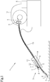
- Fig. 1 shows a schematic view of an integrated in a welding torch 2 a welding device 1 preheating 9 for heating the filler material 4, in particular welding wire.
- the filler material 4 is transported via a conveyor 3 with a conveying speed v through a hose package 19 to the weld S.
- the hose package 19 also contains the lines for further media required for the welding process, such as electricity, gas, cooling fluid, etc.
- a laser device 6 for generating a laser beam 7 with a laser power P is arranged at a suitable location.
- the laser light 7 is preferably transported via an optical waveguide 12 by the laser device 6 to a deflection device 8 of the preheating device 9, where the laser beam 7 is deflected and directed onto the filler material 4 within a conveying channel 5 of the preheating device 9.
- the deflection device 8 is formed by a prism 10.
- the laser beam 7 is guided in the region of the preheating device 9 substantially parallel to the filler material 4 and deflected by the prism 10 by an angle (180 ° - ⁇ ).
- the components of the deflection device 8 are arranged in a housing 22 to which, for example, the optical waveguide 12 is attached.
- the optical waveguide 12 may also be attached to the preheating device 9 and the deflection device 8 may be formed by the optical waveguide 12, in which the laser beam 7 is deflected several times.
- the deflection device 8 may be formed by the optical waveguide 12, in which the laser beam 7 is deflected several times.
- temperatures in the region of the point of impact of the laser beam 7 in the range between 700 K and 1000 K, and temperatures at the back of the point of impact of the laser beam 7 in the range between 500 K and 900 K, depending on the material of the filler 4 have been found to be particularly suitable. This results in temperatures of the filler material 4 in the region of the weld S from 500 K to 1000 K.
- Distances ⁇ x between the point of impact of the laser beam 7 on the filler material 4 and the weld S in the range between 0.5 and 8 cm, in particular 1 and 3 cm, have turned out to be optimal. The optimum distance ⁇ x depends on the welding method, for example MIG / MAG or TIG method.
- the laser device 6 can be designed to form a pulsed or continuous laser beam 7, in particular in the infrared wavelength range.
- the preheating device 9 may have a housing 14, in particular made of metal or ceramic.
- Fig. 2 shows a block diagram of a control device 15 for controlling the laser power P as a function of the conveying speed v of the filler material 4 or vice versa.
- the control device 15 can be arranged in the power source 18 of the welding device 1 and is formed by a corresponding microprocessor, which is also provided by the already existing Microprocessor of the welding device 1 may be formed.
- a corresponding control of each parameter can be carried out.
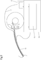
- a preheating device 9 is shown with the inventively designed deflection 8 for the laser beam 7.
- the preheating device 9 is not integrated in the welding torch 2 of the welding device 1 with the power source 18, but represents an independent structural unit.
- This variant is in welding devices 1, in which the filler material 4 or welding wire is not transported through the welding torch to the weld S, For example, in TIG welding, be applied.
- the preheating 9 is, for example, cylindrical and the conveying channel 5 is arranged axially in the center of the cylinder.
- at least one radially arranged opening, for example bore 21, is provided, which represents the connection between the deflection device 8 and the preheating device 9.
- the opening can also be designed such that a plurality of impact surfaces can be achieved on the filler material 4, which can be realized by a plurality of holes 21.
- the laser beam 7 is split, for example, by a suitable prism and in each case a partial laser beam directed from the outside of the preheater 9 arranged deflecting device 8 by a respective holes 21 on the surface of the filler material 4 (not shown).
- the at least one deflecting device 8 can also be formed by a mirror 11.
- a lens 17 may be provided for bundling or collimating the laser beam 7. It is advantageous if the laser beam 7 is not directed at right angles to the filler material 4, but slightly deviates from it by about 1 ° to 3 °, so that a reflection of the laser light from the surface of the filler material 4 are prevented back into the deflection device 8 can.
- the laser beam 7 at a more acute angle ⁇ for example from 45 ° to 60 °, be directed to the surface of the filler material 4.
- the bore 21 for forming the opening is arranged in alignment with the laser beam 7 in the direction of the desired impact surface on the surface of the filler material 4.
- the diameter of the bore 21 for guiding the laser beam 7 is made correspondingly larger.
- the deflection device 8 and / or the preheating device 9 can be cooled by appropriate cooling fluids.
- at least one temperature sensor 16 can be arranged or integrated at corresponding points.
- corresponding cooling channels are provided in the preheating device 9 and / or the deflection device 8.
- a correspondingly shaped sealing element 20 may be arranged at the end of the conveying channel 5.
- the preheating device 8 may, for example, also have a channel for a protective gas and / or be made of an electrically conductive material so that the welding current can be conducted via the preheating device 9 to a contact tube of the welding torch 2.
- the preheating device 9 may also have a receptacle, for example a thread, for the contact tube or a tube bend of the welding torch 2 (not shown).
- the welding torch 2 may also include a gas nozzle in which the preheating device 9 and the deflecting device 8 may be integrated. Thereby, the distance .DELTA.x between the impact point or the incident surface of the laser beam 7 on the filler material 4 and the weld S can be shortened.
Landscapes
- Engineering & Computer Science (AREA)
- Physics & Mathematics (AREA)
- Plasma & Fusion (AREA)
- Mechanical Engineering (AREA)
- Optics & Photonics (AREA)
- Laser Beam Processing (AREA)
Description
- Die Erfindung betrifft eine Schweißvorrichtung mit einem Schweißbrenner, einer Fördereinrichtung zur Förderung eines abschmelzenden Zusatzwerkstoffs mit einer Fördergeschwindigkeit zu einer Schweißstelle, an welcher der Zusatzwerkstoff mit Hilfe eines Lichtbogens geschmolzen wird, und mit einer Vorwärmeinrichtung zum Erwärmen des Zusatzwerkstoffs vor der Schweißstelle mittels eines in einer Laservorrichtung erzeugten Laserstrahls mit einer Laserleistung.
- Es sind Schweißvorrichtungen der gegenständlichen Art bekannt, bei welchen der Zusatzwerkstoff bzw. das Verbrauchsmaterial mit Hilfe eines Laserstrahls erwärmt wird, um die Abschmelzleistung des Zusatzwerkstoffs zu erhöhen und die Produktivität zu steigern. Beispielsweise beschreibt die
WO 2014/006488 A2 ein derartiges Verfahren bzw. System, bei welchem der Laserstrahl ungeschützt an die Schweißstelle gerichtet wird. Nachteilig dabei ist, dass bei einem solchen System die entsprechenden Richtlinien betreffend die Lasersicherheit berücksichtigt werden müssen und das System für manuelle Schweißbrenner daher ungeeignet ist. - Andere Vorrichtungen für das Erhitzen des Zusatzwerkstoffs beaufschlagen diesen mit Wechselstrom, wodurch die Verlustleistung zu einer Erwärmung des Zusatzwerkstoffs führt. Beispielsweise beschreibt die
EP 2 777 858 A1 , welche als nächstliegender Stand der Technik angesehen wird, eine derartige Heizvorrichtung zum Erwärmen eines Zusatzwerkstoffs beim Lichtbogenschweißen. Nachteilig dabei ist, dass der zum Erwärmen verwendete Wechselstrom ein magnetisches Feld erzeugt, welches den Schweiß-Lichtbogen abstößt bzw. anzieht und somit den Schweißpunkt beeinflusst. - Die Aufgabe der vorliegenden Erfindung besteht darin, eine oben genannte Schweißvorrichtung zu schaffen, welche eine Erwärmung des Zusatzwerkstoffs mit Hilfe des Laserstrahls ermöglicht, ohne dass bestimmte Sicherheitsmaßnahmen aufgrund des Laserlichts ergriffen werden müssen. Die Erwärmung des Zusatzwerkstoffs soll möglichst effizient und wirkungsvoll sein. Nachteile bekannter Schweißvorrichtung sollen vermieden oder zumindest reduziert werden.
- Gelöst wird die erfindungsgemäße Aufgabe dadurch, dass die Vorwärmeinrichtung einen Förderkanal für den Zusatzwerkstoff aufweist, und zumindest eine Umlenkeinrichtung zum Umlenken des Laserstrahls auf den Zusatzwerkstoff derart an der Vorwärmeinrichtung befestigt ist, dass der Laserstrahl innerhalb des Förderkanals der Vorwärmeinrichtung auf den Zusatzwerkstoff auftrifft. Durch die verwendete zumindest eine Umlenkeinrichtung ist es möglich, die Laservorrichtung an einem dafür geeigneten Platz der Schweißvorrichtung anzuordnen und das Laserlicht über die Umlenkeinrichtung an die gewünschte Stelle auf dem Zusatzwerkstoff zu richten. Dadurch, dass der Laserstrahl innerhalb des Förderkanals der Vorwärmeinrichtung, in dem der Zusatzwerkstoff befördert wird, auf diesen auftrifft, befindet sich der Laserstrahl in einem geschlossenen System, weshalb keine Sicherheitsvorkehrungen zu Vermeidung, dass Laserlicht in die Augen des Benutzers gelangt, getroffen werden müssen. Die erfindungsgemäßen Merkmale können relativ einfach und kostengünstig auch an vorhandenen Schweißvorrichtungen angeordnet werden, sodass eine breite Anwendung möglich ist. Durch die Erwärmung des Zusatzwerkstoffs kommt es zu einer Erhöhung der Abschmelzleistung des Zusatzwerkstoffs, wodurch einerseits eine höhere Spaltüberbrückbarkeit oder eine höhere Schweißgeschwindigkeit erzielbar ist.
- Die zumindest eine Umlenkeinrichtung kann in einfachster Weise durch einen Spiegel gebildet sein. Dabei kommen sowohl plane Spiegel als auch gewölbte Spiegel in Frage, je nachdem ob ein Fokussieren oder Auffächern des Laserstrahls gewünscht wird.
- Ebenso kann die zumindest eine Umlenkeinrichtung durch ein Prisma gebildet sein. Auch beim Prisma kann die Reflexionsfläche an welcher der Laserstrahl umgelenkt wird, sowohl eben als auch gekrümmt ausgebildet sein, je nachdem ob eine Fokussierung oder eine Auffächerung des Laserstrahls gewünscht wird.
- Wenn zumindest eine Linse vor oder nach der zumindest einen Umlenkeinrichtung vorgesehen ist, kann der Laserstrahl gebündelt oder kollimiert werden. Eine derartige Linse kann anstelle eines gekrümmt ausgebildeten Spiegels oder Prismas oder auch zusätzlich vorgesehen werden, um den Durchmesser des auf den Zusatzwerkstoff zu dessen Erwärmung auftreffenden Lichtpunkts einstellen zu können. Je nach Anordnung der Linse kann der Fokus des Laserstrahls eingestellt und optimiert werden. Üblicherweise werden derartige Linsen aus Glas oder einem Glasderivat hergestellt.
- Die zumindest eine Umlenkeinrichtung ist vorzugsweise zum Umlenken des Laserstrahles auf den Zusatzwerkstoff in einem Abstand zwischen 0,5 und 8 cm, insbesondere 1 und 3 cm, von der Schweißstelle ausgebildet. Diese Werte haben sich als besonders bevorzugt herausgestellt, da der Erwärmungspunkt nicht zu nahe an der Schweißstelle angeordnet werden soll, um eine Ausbreitung der Wärme innerhalb des Zusatzwerkstoffs zu ermöglichen aber auch nicht zu weit von der Schweißstelle entfernt sein soll um ein Auskühlen des Zusatzwerkstoffs während des Transports zur Schweißstelle zu verhindern. Dabei ergibt sich die untere Grenze des bevorzugten Bereichs hauptsächlich aus konstruktiven Bedingungen. Beim WIG-Schweißen liegt der bevorzugte Abstand beispielsweise zwischen 1 und 3 cm, beim MIG/MAG-Schweißen zwischen 3 und 5 cm.
- Zwischen der Laservorrichtung und der zumindest einen Umlenkeinrichtung ist vorzugsweise ein Lichtwellenleiter angeordnet. Über einen solchen Lichtwellenleiter kann das Laserlicht auch über weitere Strecken von der Laservorrichtung zur Umlenkeinrichtung ohne erhebliche Leistungsverluste transportiert werden, wodurch die Baugröße im Bereich der Schweißstelle nicht wesentlich erhöht werden muss. Beispielsweise kann die Laservorrichtung im Bereich der Stromquelle der Schweißvorrichtung angeordnet sein und das Laserlicht über den Lichtwellenleiter zum Schweißbrenner transportiert werden. Die Umlenkeinrichtung kann auch durch den Lichtwellenleiter mit ausgebildet werden. Dies kann konstruktive Vereinfachungen bewirken und zu einer einfach herstellbaren Umlenkeinrichtung führen.
- Wenn die zumindest eine Umlenkeinrichtung bewegbar angeordnet ist, können verschiedene Verbesserungen und Effekte erzielt werden. Beispielsweise kann der Auftreffpunkt des Laserstrahls an der Oberfläche des Zusatzwerkstoffs verändert werden um eine gleichmäßige Erwärmung des Zusatzwerkstoffs zu erzielen. Beispielsweise kann das Laserlicht in einer oszillierenden Bewegung um die Mittellinie des Zusatzwerkstoffs bewegt werden. Die Bewegung kann durch entsprechende Einrichtungen, beispielsweise Schrittmotoren, bewerkstelligt werden.
- Die zumindest eine Umlenkeinrichtung kann zur Umlenkung des Laserstrahls in einem Winkel zwischen 45° und 90° zur Förderrichtung des Zusatzwerkstoffs ausgebildet sein. Wird das Laserlicht in einem schrägen Winkel zur Förderrichtung des Zusatzwerkstoffs auf diesen gerichtet, resultiert ein größerer Auftreffpunkt bzw. eine größere Auftrefffläche des Laserlichts am Zusatzwerkstoff und somit eine größere Erwärmungsfläche im Gegensatz zu einem rechten Winkel. Dies kann zu einer gleichmäßigeren Erwärmung des Zusatzwerkstoffs führen. Als vorteilhaft hat sich auch die Wahl eines geringfügig vom rechten Winkel abweichenden Winkel herausgestellt, da dadurch eine Reflexion des Laserlichts von der Oberfläche des Zusatzwerkstoffs zurück in die Umlenkeinrichtung verhindert werden kann. Beispielsweise kann das Laserlicht in einen Winkel von 78° bis 89° zur Förderrichtung des Zusatzwerkstoffs umgelenkt werden.
- Wenn die Oberfläche des Förderkanals für den Zusatzwerkstoff poliert ist, kann erreicht werden, dass nahezu kein Laserlicht durch Absorption an der Oberfläche des Förderkanals verloren geht, sondern durch mehrmalige Reflexion von der Oberfläche des Förderkanals schlussendlich zum größten Teil auf den Zusatzwerkstoff auftrifft und zur Erwärmung desselben beiträgt. Je nach verwendetem Material für die Fördereinrichtung, in welcher der Förderkanal angeordnet ist, wird das Polieren der Oberfläche des Förderkanals mit verschiedenen Methoden durchzuführen zu sein. Auch bestimmte Beschichtungen der Oberfläche des Förderkanals zur Erzielung einer möglichst hohen Reflexion des Laserlichts sind möglich.
- Die Vorwärmeinrichtung kann im Schweißbrenner der Schweißvorrichtung integriert sein. Dadurch wird die Baugröße des Schweißbrenners nur unwesentlich beeinflusst und die Handhabung des Schweißbrenners kann in gewohnter Weise vom Schweißer vorgenommen werden.
- Zur Kühlung der zumindest einen Umlenkeinrichtung und bzw. oder Vorwärmeinrichtung kann eine Kühlvorrichtung vorgesehen sein. Die Kühlung der Umlenkeinrichtung und der Vorwärmeinrichtung erfolgt vorzugsweise durch entsprechend geeignete Kühlfluide insbesondere Kühlflüssigkeiten. Dabei können entsprechende Kühlkanäle in der Umlenkeinrichtung und bzw. oder Vorwärmeinrichtung vorgesehen sein, durch welche das Kühlfluid transportiert wird.
- Gemäß einem weiteren Merkmal der Erfindung ist eine Steuereinrichtung zur Steuerung der Laserleistung in Abhängigkeit der Fördergeschwindigkeit des Zusatzwerkstoffs und bzw. oder zur Steuerung der Fördergeschwindigkeit des Zusatzwerkstoffs in Abhängigkeit der Laserleistung vorgesehen. Durch eine derartige Steuereinrichtung wird gewährleistet, dass die für die gewünschte Erwärmung des Zusatzwerkstoffs notwendige Laserleistung in den Zusatzwerkstoff eingebracht wird, unabhängig von der Fördergeschwindigkeit des Zusatzwerkstoffs. Die Steuereinrichtung kann natürlich auch durch die ohnehin vorhandene Steuereinrichtung der Schweißvorrichtung gebildet sein.
- Die Laserleistung beträgt idealerweise zwischen 10 W und 2 kW. Derartige Laserleistungen haben sich für eine effiziente Erwärmung des Zusatzwerkstoffs beim Schweißverfahren als geeignet bzw. ausreichend herausgestellt. Die Laservorrichtung kann zur Bildung eines gepulsten oder kontinuierlichen Laserstrahls ausgebildet sein.
- Wenn ein Temperatursensor vorgesehen ist, kann einerseits eine Regelung der Laserleistung zur Erzielung einer gewünschten Temperatur und andererseits auch eine Warnung vor unzulässig hohen Temperaturen im Bereich der Umlenkeinrichtung oder des Förderkanals der Fördereinrichtung erzielt werden. Der Temperatursensor kann in der Vorwärmeinrichtung in der Nähe des Förderkanals oder am Ausgang des Förderkanals angeordnet werden.
- Die Laservorrichtung ist vorzugsweise zur Erzeugung eines Laserstrahls im Infrarot-Wellenlängenbereich ausgebildet. Infrarotlaser sind für die Erwärmung des Zusatzwerkstoffs besonders geeignet und auch in verschiedenen Leistungsgruppen kostengünstig erhältlich. Je nach Material des Zusatzwerkstoffs können jedoch auch andere Wellenlängenbereiche des Lasers von Vorteil sein.
- Die Erfindung wird anhand der beigefügten Zeichnungen näher erläutert. Darin zeigen:
- Fig. 1
- eine schematische Ansicht einer in einem Schweißbrenner integrierten Vorwärmeinrichtung zum Erwärmen des Zusatzwerkstoffs;
- Fig. 2
- ein Blockschaltbild einer Steuereinrichtung zur Steuerung der Laserleistung in Abhängigkeit der Fördergeschwindigkeit des Zusatzwerkstoffs; und
- Fig. 3
- eine Variante einer Vorwärmeinrichtung mit der erfindungsgemäß ausgebildeten Umlenkeinrichtung für den Laserstrahl.
-
Fig. 1 zeigt eine schematische Ansicht einer in einem Schweißbrenner 2 einer Schweißvorrichtung 1 integrierten Vorwärmeinrichtung 9 zum Erwärmen des Zusatzwerkstoffs 4, insbesondere Schweißdrahts. Der Zusatzwerkstoff 4 wird über eine Fördereinrichtung 3 mit einer Fördergeschwindigkeit v durch ein Schlauchpaket 19 zur Schweißstelle S transportiert. Im Schlauchpaket 19 befinden sich auch die Leitungen für weitere für den Schweißprozess erforderliche Medien, wie Strom, Gas, Kühlfluid, usw. Eine Laservorrichtung 6 zur Erzeugung eines Laserstrahls 7 mit einer Laserleistung P ist an einer geeigneten Stelle angeordnet. Vorzugsweise über einen Lichtwellenleiter 12 wird das Laserlicht 7 von der Laservorrichtung 6 zu einer Umlenkeinrichtung 8 der Vorwärmeinrichtung 9 transportiert, wo der Laserstrahl 7 umgelenkt und innerhalb eines Förderkanals 5 der Vorwärmeinrichtung 9 auf den Zusatzwerkstoff 4 gerichtet wird. Im dargestellten Ausführungsbeispiel ist die Umlenkeinrichtung 8 durch ein Prisma 10 gebildet. Es wird also der Laserstrahl 7 im Bereich der Vorwärmeinrichtung 9 im Wesentlichen parallel zum Zusatzwerkstoff 4 geführt und durch das Prisma 10 um einen Winkel (180°-α) umgelenkt. Die Komponenten der Umlenkeinrichtung 8 sind in einem Gehäuse 22 angeordnet, an welchem beispielsweise der Lichtwellenleiter 12 befestigt ist. Bei einer alternativen kompakten Ausführungsform kann der Lichtwellenleiter 12 auch an der Vorwärmeinrichtung 9 befestigt sein und die Umlenkeinrichtung 8 durch den Lichtwellenleiter 12 gebildet sein, in welcher der Laserstrahl 7 mehrmals umgelenkt wird. Dadurch dass der Laserstrahl 7 nur innerhalb der Vorwärmeinrichtung 9 und allenfalls durch den Lichtwellenleiter 12 in einem geschlossenen System transportiert wird, sind keine Sicherheitsmaßnahmen zur Erfüllung der Laserrichtlinien erforderlich. Durch den auftreffenden Laserstrahl 7 am Zusatzwerkstoff 4 wird dieser entsprechend erwärmt, wodurch die Abschmelzleistung des Zusatzwerkstoffs 4 an der Schweißstelle S erhöht werden kann. Dabei haben sich Temperaturen im Bereich des Auftreffpunkts des Laserstrahls 7 im Bereich zwischen 700 K und 1000 K, und Temperaturen an der Rückseite des Auftreffpunkts des Laserstrahls 7 im Bereich zwischen 500 K und 900 K, abhängig vom Material des Zusatzwerkstoffs 4 als besonders geeignet herausgestellt. Dadurch resultieren Temperaturen des Zusatzwerkstoffs 4 im Bereich der Schweißstelle S von 500 K bis 1000 K. Abstände Δx zwischen dem Auftreffpunkt des Laserstrahls 7 auf den Zusatzwerkstoff 4 und der Schweißstelle S im Bereich zwischen 0.5 und 8 cm, insbesondere 1 und 3 cm, haben sich als optimal herausgestellt. Der optimale Abstand Δx hängt dabei vom Schweißverfahren, beispielsweise MIG/MAG- oder WIG-Verfahren, ab. - Die Laservorrichtung 6 kann zur Bildung eines gepulsten oder kontinuierlichen Laserstrahls 7, insbesondere im Infrarotwellenlängenbereich, ausgebildet sein.
- Um eine möglichst gute Reflexion des Laserlichts an der Oberfläche des Förderkanals 5 der Vorwärmeinrichtung 9 zu erzielen, kann dieser poliert oder mit einer entsprechenden Beschichtung versehen sein. Die Vorwärmeinrichtung 9 kann ein Gehäuse 14, insbesondere aus Metall oder Keramik, aufweisen.
-
Fig. 2 zeigt ein Blockschaltbild einer Steuereinrichtung 15 zur Steuerung der Laserleistung P in Abhängigkeit der Fördergeschwindigkeit v des Zusatzwerkstoffs 4 bzw. umgekehrt. Die Steuereinrichtung 15 kann in der Stromquelle 18 der Schweißvorrichtung 1 angeordnet sein und ist durch einen entsprechenden Mikroprozessor gebildet, der auch durch den ohnehin vorhandenen Mikroprozessor der Schweißvorrichtung 1 gebildet sein kann. Durch Verarbeitung der Laserleistung P einerseits und der Fördergeschwindigkeit v des Zusatzwerkstoffs 4 andererseits kann eine entsprechende Regelung jeweils eines Parameters erfolgen. - In
Fig. 3 ist eine alternative Ausführungsvariante einer Vorwärmeinrichtung 9 mit der erfindungsgemäß ausgebildeten Umlenkeinrichtung 8 für den Laserstrahl 7 dargestellt. Die Vorwärmeinrichtung 9 ist nicht im Schweißbrenner 2 der Schweißvorrichtung 1 mit der Stromquelle 18 integriert, sondern stellt eine eigenständige Baueinheit dar. Diese Variante wird bei Schweißvorrichtungen 1, bei welchen der Zusatzwerkstoff 4 bzw. Schweißdraht nicht durch den Schweißbrenner an die Schweißstelle S befördert wird, beispielsweise beim WIG-Schweißen, angewendet werden. Die Vorwärmeinrichtung 9 ist beispielsweise zylinderförmig ausgebildet und der Förderkanal 5 axial im Zentrum des Zylinders angeordnet. Für den Eintritt des Laserstrahls 7 ist zumindest eine radial angeordnete Öffnung, beispielsweise Bohrung 21, vorgesehen, welche die Verbindung zwischen der Umlenkeinrichtung 8 und der Vorwärmeinrichtung 9 darstellt. Die Öffnung kann auch derart ausgebildet sein, dass mehrere Auftreffflächen am Zusatzwerkstoff 4 erzielt werden können, was durch mehrere Bohrungen 21 realisiert werden kann. Dabei wird der Laserstrahl 7 beispielsweise durch ein geeignetes Prisma aufgespaltet und jeweils ein Teillaserstrahl von der außen an der Vorwärmeinrichtung 9 angeordneten Umlenkeinrichtung 8 durch je eine Bohrungen 21 auf die Oberfläche des Zusatzwerkstoffs 4 gerichtet (nicht dargestellt). - Die zumindest eine Umlenkeinrichtung 8 kann auch durch einen Spiegel 11 gebildet sein. Vor und nach der Umlenkeinrichtung 8 kann eine Linse 17 zum Bündeln oder Kollimieren des Laserstrahls 7 vorgesehen sein. Von Vorteil ist es, wenn der Laserstrahl 7 nicht im rechten Winkel auf dem Zusatzwerkstoff 4 gerichtet wird, sondern davon geringfügig um etwa 1° bis 3° abweichend, sodass eine Reflexion des Laserlichts von der Oberfläche des Zusatzwerkstoffs 4 zurück in die Umlenkeinrichtung 8 unterbunden werden kann. Zur Erzielung eines größeren Auftreffpunkts bzw. einer Auftrefffläche an der Oberfläche des Zusatzwerkstoffs 4 kann der Laserstrahl 7 auch in einem spitzeren Winkel α, beispielsweise von 45° bis 60°, auf die Oberfläche des Zusatzwerkstoffs 4 gerichtete werden. Die Bohrung 21 zur Bildung der Öffnung ist entsprechend fluchtend mit dem Laserstrahl 7 in Richtung der gewünschten Auftrefffläche an der Oberfläche des Zusatzwerkstoffs 4 angeordnet.
- Durch beweglich angeordnete Umlenkeinrichtungen 8 kann eine Veränderung des Auftreffpunkts des Laserstrahls 7 auf den Zusatzwerkstoff 4 und somit eine gleichmäßigere Erwärmung des Zusatzwerkstoffs 4 erzielt werden. Dabei wird der Durchmesser der Bohrung 21 zur Führung des Laserstrahls 7 entsprechend größer ausgeführt.
- Über eine entsprechende Kühlvorrichtung 13 kann die Umlenkeinrichtung 8 und bzw. oder die Vorwärmeinrichtung 9 durch entsprechende Kühlfluide gekühlt werden. Zur Regelung kann an entsprechenden Stellen zumindest ein Temperatursensor 16 angeordnet bzw. integriert sein. Dazu sind in der Vorwärmeinrichtung 9 und bzw. oder der Umlenkeinrichtung 8 entsprechende Kühlkanäle vorgesehen.
- Zur Verhinderung des Austritts von Laserlicht aus der Vorwärmeinrichtung 9 kann am Ende des Förderkanals 5 ein entsprechend gestaltetes Dichtungselement 20 angeordnet sein.
- Die Vorwärmeinrichtung 8 kann beispielsweise auch einen Kanal für ein Schutzgas aufweisen und bzw. oder aus einem elektrisch leitenden Material gefertigt sein, sodass der Schweißstrom über die Vorwärmeinrichtung 9 an ein Kontaktrohr des Schweißbrenners 2 geführt werden kann. Hierfür kann die Vorwärmeinrichtung 9 auch eine Aufnahme, beispielsweise ein Gewinde, für das Kontaktrohr oder einen Rohrbogen des Schweißbrenners 2 aufweisen (nicht dargestellt).
- Der Schweißbrenner 2 kann auch eine Gasdüse beinhalten, in welcher die Vorwärmeinrichtung 9 und die Umlenkeinrichtung 8 integriert sein kann. Dadurch kann der Abstand Δx zwischen dem Auftreffpunkt oder der Auftrefffläche des Laserstrahls 7 auf dem Zusatzwerkstoff 4 und der Schweißstelle S verkürzt werden.
Claims (15)
- Schweißvorrichtung (1) mit einem Schweißbrenner (2), einer Fördereinrichtung (3) zur Förderung eines abschmelzenden Zusatzwerkstoffs (4) mit einer Fördergeschwindigkeit (v) zu einer Schweißstelle (S), an welcher der Zusatzwerkstoff (4) mit Hilfe eines Lichtbogens (L) geschmolzen wird, und mit einer einen Förderkanal (5) für den Zusatzwerkstoff aufweisenden Vorwärmeinrichtung (9) zum Erwärmen des Zusatzwerkstoffs (4) vor der Schweißstelle (S), dadurch gekennzeichnet, dass die Vorwärmeinrichtung (9) zum Erwärmen des Zusatzwerkstoffs (4) vor der Schweißstelle (S) mittels eines in einer Laservorrichtung (6) erzeugten Laserstrahls (7) mit einer Laserstrahlung (P) geeignet ist, und zumindest eine Umlenkeinrichtung (8) zum Umlenken des Laserstrahls (7) auf den Zusatzwerkstoff (4) derart an der Vorwärmeinrichtung (9) befestigt ist, dass der Laserstrahl (7) innerhalb des Förderkanals (5) der Vorwärmeinrichtung (9) auf den Zusatzwerkstoff (4) auftrifft.
- Schweißvorrichtung (1) nach Anspruch 1, dadurch gekennzeichnet, dass die zumindest eine Umlenkeinrichtung (8) durch einen Spiegel (11) gebildet ist.
- Schweißvorrichtung (1) nach Anspruch 1 oder 2, dadurch gekennzeichnet, dass die zumindest eine Umlenkeinrichtung (8) durch ein Prisma (10) gebildet ist.
- Schweißvorrichtung (1) nach einem der Ansprüche 1 bis 3, dadurch gekennzeichnet, dass zumindest eine Linse (17) zum Bündeln oder Kollimieren des Laserstrahls (7) vorgesehen ist.
- Schweißvorrichtung (1) nach einem der Ansprüche 1 bis 4, dadurch gekennzeichnet, dass die zumindest eine Umlenkeinrichtung (8) zum Umlenken des Laserstrahles (7) auf den Zusatzwerkstoff (4) in einem Abstand (Δx) zwischen 0,5 und 8 cm, insbesondere 1 und 3 cm, von der Schweißstelle (S) ausgebildet ist.
- Schweißvorrichtung (1) nach einem der Ansprüche 1 bis 5, dadurch gekennzeichnet, dass zwischen der Laservorrichtung (6) und der zumindest einen Umlenkeinrichtung (8) ein Lichtwellenleiter (12) angeordnet ist.
- Schweißvorrichtung (1) nach einem der Ansprüche 1 bis 6, dadurch gekennzeichnet, dass die zumindest eine Umlenkeinrichtung (8) bewegbar angeordnet ist.
- Schweißvorrichtung (1) nach einem der Ansprüche 1 bis 7, dadurch gekennzeichnet, dass die zumindest eine Umlenkeinrichtung (8) zur Umlenkung des Laserstrahls (7) in einem Winkel (α) zwischen 45° und 90° zur Förderrichtung des Zusatzwerkstoffs (4) ausgebildet ist.
- Schweißvorrichtung (1) nach einem der Ansprüche 1 bis 8, dadurch gekennzeichnet, dass die Oberfläche des Förderkanals (5) für den Zusatzwerkstoff (4) poliert ist.
- Schweißvorrichtung (1) nach einem der Ansprüche 1 bis 9, dadurch gekennzeichnet, dass die Vorwärmeinrichtung (9) im Schweißbrenner (2) integriert ist.
- Schweißvorrichtung (1) nach einem der Ansprüche 1 bis 10, dadurch gekennzeichnet, dass eine Kühlvorrichtung (13) zur Kühlung der zumindest einen Umlenkeinrichtung (8) und bzw. oder Vorwärmeinrichtung (9) vorgesehen ist.
- Schweißvorrichtung (1) nach einem der Ansprüche 1 bis 11, dadurch gekennzeichnet, dass eine Steuereinrichtung (15) zur Steuerung der Laserleistung (P) in Abhängigkeit der Fördergeschwindigkeit (v) des Zusatzwerkstoffs (4) und bzw. oder zur Steuerung der Fördergeschwindigkeit (v) des Zusatzwerkstoffs (4) in Abhängigkeit der Laserleistung (P) vorgesehen ist.
- Schweißvorrichtung (1) nach einem der Ansprüche 1 bis 12, dadurch gekennzeichnet, dass Laserleistung (P) zwischen 10 W und 2 kW beträgt.
- Schweißvorrichtung (1) nach einem der Ansprüche 1 bis 13, dadurch gekennzeichnet, dass ein Temperatursensor (16) vorgesehen ist.
- Schweißvorrichtung (1) nach einem der Ansprüche 1 bis 14, dadurch gekennzeichnet, dass die Laservorrichtung (6) zur Erzeugung eines Laserstrahls (7) im Infrarot-Wellenlängenbereich ausgebildet ist.
Priority Applications (1)
| Application Number | Priority Date | Filing Date | Title |
|---|---|---|---|
| PL17706752T PL3265263T3 (pl) | 2016-02-23 | 2017-02-22 | Urządzenie spawalnicze z laserowym urządzeniem do wstępnego podgrzewania drutu dodatkowego |
Applications Claiming Priority (2)
| Application Number | Priority Date | Filing Date | Title |
|---|---|---|---|
| EP16156979 | 2016-02-23 | ||
| PCT/EP2017/054020 WO2017144515A1 (de) | 2016-02-23 | 2017-02-22 | Schweissvorrichtung mit einer laservorwärmeinrichtung für zusatzdraht |
Publications (2)
| Publication Number | Publication Date |
|---|---|
| EP3265263A1 EP3265263A1 (de) | 2018-01-10 |
| EP3265263B1 true EP3265263B1 (de) | 2018-12-12 |
Family
ID=55442668
Family Applications (1)
| Application Number | Title | Priority Date | Filing Date |
|---|---|---|---|
| EP17706752.7A Active EP3265263B1 (de) | 2016-02-23 | 2017-02-22 | Schweissvorrichtung mit einer laservorwärmeinrichtung für zusatzdraht |
Country Status (5)
| Country | Link |
|---|---|
| US (1) | US11000913B2 (de) |
| EP (1) | EP3265263B1 (de) |
| CN (1) | CN108698149B (de) |
| PL (1) | PL3265263T3 (de) |
| WO (1) | WO2017144515A1 (de) |
Families Citing this family (9)
| Publication number | Priority date | Publication date | Assignee | Title |
|---|---|---|---|---|
| US10675699B2 (en) | 2015-12-10 | 2020-06-09 | Illinois Tool Works Inc. | Systems, methods, and apparatus to preheat welding wire |
| US11524354B2 (en) | 2017-06-09 | 2022-12-13 | Illinois Tool Works Inc. | Systems, methods, and apparatus to control weld current in a preheating system |
| US11229977B2 (en) | 2018-07-19 | 2022-01-25 | Lincoln Global, Inc. | Laser hot wire additive deposition head with omni-directional build path |
| US11446756B2 (en) | 2018-08-30 | 2022-09-20 | Illinois Tool Works Inc. | Systems and methods for wire surface oxidation removal and/or wire preheating using a tungsten arc |
| CN114258398A (zh) | 2019-06-13 | 2022-03-29 | 总医院公司 | 工程化的人内源性病毒样颗粒及使用其递送至细胞的方法 |
| US11745283B2 (en) | 2019-08-27 | 2023-09-05 | Illinois Tool Works Inc. | Methods for wire surface oxidation removal and/or wire preheating using polyphase electric arc preheating |
| US11772182B2 (en) | 2019-12-20 | 2023-10-03 | Illinois Tool Works Inc. | Systems and methods for gas control during welding wire pretreatments |
| BR112023001272A2 (pt) | 2020-07-24 | 2023-04-04 | Massachusetts Gen Hospital | Partículas semelhantes a vírus aprimoradas e métodos de uso das mesmas para entrega às células |
| WO2024062917A1 (ja) * | 2022-09-22 | 2024-03-28 | 三菱電機株式会社 | 自動ろう付装置及び自動ろう付方法 |
Family Cites Families (14)
| Publication number | Priority date | Publication date | Assignee | Title |
|---|---|---|---|---|
| US3597578A (en) * | 1967-03-16 | 1971-08-03 | Nat Res Dev | Thermal cutting apparatus and method |
| SU1166943A1 (ru) | 1984-02-20 | 1985-07-15 | Краматорский Индустриальный Институт | Способ дуговой сварки порошковой проволокой |
| JPH04280915A (ja) * | 1991-01-10 | 1992-10-06 | Nippon Steel Corp | 金属線材のレーザ熱処理法およびその装置 |
| US5961862A (en) * | 1995-11-30 | 1999-10-05 | The Regents Of The University Of California | Deposition head for laser |
| KR100497878B1 (ko) * | 1996-04-29 | 2005-09-27 | 웨스팅하우스 일렉트릭 코포레이션 | 고온와이어가스텅스텐아크용접방법 |
| US6191379B1 (en) * | 1999-04-05 | 2001-02-20 | General Electric Company | Heat treatment for weld beads |
| US6521861B2 (en) * | 2000-02-07 | 2003-02-18 | General Electric Company | Method and apparatus for increasing welding rate for high aspect ratio welds |
| JP3686317B2 (ja) * | 2000-08-10 | 2005-08-24 | 三菱重工業株式会社 | レーザ加工ヘッド及びこれを備えたレーザ加工装置 |
| JP2005224837A (ja) | 2004-02-13 | 2005-08-25 | Nissan Motor Co Ltd | レーザ溶接装置 |
| US7476597B2 (en) * | 2006-07-10 | 2009-01-13 | Texas Instruments Incorporated | Methods and systems for laser assisted wirebonding |
| US9095928B2 (en) | 2012-07-06 | 2015-08-04 | Lincoln Global, Inc. | Method and system for heating consumable during hot wire |
| US20140042131A1 (en) | 2012-08-10 | 2014-02-13 | Lincoln Global, Inc. | Laser welding consumable |
| EP2777858B1 (de) | 2013-03-15 | 2017-10-11 | Ewm Ag | Erhitzen eines Schweißzusatzes für das Lichtbogenschweißen |
| US10675699B2 (en) * | 2015-12-10 | 2020-06-09 | Illinois Tool Works Inc. | Systems, methods, and apparatus to preheat welding wire |
-
2017
- 2017-02-22 PL PL17706752T patent/PL3265263T3/pl unknown
- 2017-02-22 EP EP17706752.7A patent/EP3265263B1/de active Active
- 2017-02-22 US US15/568,134 patent/US11000913B2/en active Active
- 2017-02-22 CN CN201780001268.9A patent/CN108698149B/zh active Active
- 2017-02-22 WO PCT/EP2017/054020 patent/WO2017144515A1/de not_active Ceased
Non-Patent Citations (1)
| Title |
|---|
| None * |
Also Published As
| Publication number | Publication date |
|---|---|
| US20180085842A1 (en) | 2018-03-29 |
| PL3265263T3 (pl) | 2019-06-28 |
| CN108698149A (zh) | 2018-10-23 |
| US11000913B2 (en) | 2021-05-11 |
| WO2017144515A1 (de) | 2017-08-31 |
| CN108698149B (zh) | 2020-03-03 |
| EP3265263A1 (de) | 2018-01-10 |
Similar Documents
| Publication | Publication Date | Title |
|---|---|---|
| EP3265263B1 (de) | Schweissvorrichtung mit einer laservorwärmeinrichtung für zusatzdraht | |
| EP2142333B1 (de) | Vorrichtung zum bearbeiten einer oberfläche eines werkstücks mittels laserstrahlung | |
| DE102012218487B4 (de) | Verfahren und Vorrichtung zur Herstellung einer dreidimensionalen Struktur an der Oberfläche eines metallischen Werkstücks | |
| DE102010018686B4 (de) | Vorrichtung und Verfahren zum Laser-Auftragschweißen mit pulverförmigem Zusatzwerkstoff | |
| DE102012207201B3 (de) | Verfahren zum laserunterstützten Plasmaschneiden oder Plasmaschweißen und Vorrichtung dafür | |
| DE3916264C2 (de) | ||
| EP3651932B1 (de) | Verfahren und vorrichtung zum fügen von mindestens zwei werkstücken | |
| WO2017080736A1 (de) | Vorrichtung zum laserstrahl-auftragschweissen mit pendelbewegung | |
| EP3603872B1 (de) | Vorrichtung und verfahren zum bearbeiten eines werkstücks mittels laserstrahlung | |
| WO2017178580A1 (de) | Vorrichtung zur bearbeitung einer oberfläche eines werkstücks mit einem laserstrahl und verfahren zum betrieb der vorrichtung | |
| DE102016106960A1 (de) | Vorrichtung zur Bearbeitung einer Oberfläche eines Werkstücks mit einem Laserstrahl und Verfahren zum Betrieb der Vorrichtung | |
| EP3017901A1 (de) | Wig-schweissbrenner mit kreisbogenförmiger führung | |
| DE102023102044A1 (de) | Verfahren zum Beschichten metallischer Werkstücke | |
| DE212014000039U1 (de) | System zum Laser-Warmdrahtbeschichten eines Rohrendes | |
| EP4101574B1 (de) | Vorrichtung zum elektrischen widerstandsauftragsschmelzen, insbesondere widerstandsschweissen oder widerstandslöten, verfahren zum mittels jeweiliger laserstrahlen unterstützten aufbringen eines zusatzwerkstoffes sowie verwendung einer vorrichtung | |
| DE19741028C1 (de) | Vorrichtung zum Härten der Innenkontur eines Waffenrohres mit Laserstrahlung | |
| EP3122511A1 (de) | Verfahren und vorrichtung zum laserstrahlschneiden | |
| EP3837103A1 (de) | Bauteiledruckverfahren und vorrichtungen hierfür | |
| WO2023089194A1 (de) | Vorrichtung zur bearbeitung einer oberfläche eines werkstücks mit einer kombination aus atmosphärischem plasmastrahl und laserstrahl | |
| EP3138650A1 (de) | Vorrichtung und verfahren zum lichtbogenschweissen oder lichtbogenlöten mit einer abschmelzenden elektrode | |
| DE102014221806A1 (de) | Vorrichtung zum Laserschweißen mit einem Zusatzwerkstoff | |
| DE102017126697A1 (de) | Verfahren und Vorrichtung zum Fügen von Werkstücken | |
| DE202023002910U1 (de) | Technik zum Beschichten metallischer Werkstücke | |
| DE202023002889U1 (de) | Technik zum Beschichten metallischer Werkstücke | |
| WO2024156621A2 (de) | Verfahren zum beschichten metallischer werkstücke |
Legal Events
| Date | Code | Title | Description |
|---|---|---|---|
| STAA | Information on the status of an ep patent application or granted ep patent |
Free format text: STATUS: UNKNOWN |
|
| STAA | Information on the status of an ep patent application or granted ep patent |
Free format text: STATUS: THE INTERNATIONAL PUBLICATION HAS BEEN MADE |
|
| PUAI | Public reference made under article 153(3) epc to a published international application that has entered the european phase |
Free format text: ORIGINAL CODE: 0009012 |
|
| STAA | Information on the status of an ep patent application or granted ep patent |
Free format text: STATUS: REQUEST FOR EXAMINATION WAS MADE |
|
| 17P | Request for examination filed |
Effective date: 20171004 |
|
| AK | Designated contracting states |
Kind code of ref document: A1 Designated state(s): AL AT BE BG CH CY CZ DE DK EE ES FI FR GB GR HR HU IE IS IT LI LT LU LV MC MK MT NL NO PL PT RO RS SE SI SK SM TR |
|
| AX | Request for extension of the european patent |
Extension state: BA ME |
|
| REG | Reference to a national code |
Ref country code: DE Ref legal event code: R079 Ref document number: 502017000506 Country of ref document: DE Free format text: PREVIOUS MAIN CLASS: B23K0009100000 Ipc: B23K0026348000 |
|
| GRAP | Despatch of communication of intention to grant a patent |
Free format text: ORIGINAL CODE: EPIDOSNIGR1 |
|
| STAA | Information on the status of an ep patent application or granted ep patent |
Free format text: STATUS: GRANT OF PATENT IS INTENDED |
|
| RIC1 | Information provided on ipc code assigned before grant |
Ipc: B23K 26/348 20140101AFI20180628BHEP |
|
| DAV | Request for validation of the european patent (deleted) | ||
| DAX | Request for extension of the european patent (deleted) | ||
| INTG | Intention to grant announced |
Effective date: 20180731 |
|
| GRAS | Grant fee paid |
Free format text: ORIGINAL CODE: EPIDOSNIGR3 |
|
| GRAA | (expected) grant |
Free format text: ORIGINAL CODE: 0009210 |
|
| STAA | Information on the status of an ep patent application or granted ep patent |
Free format text: STATUS: THE PATENT HAS BEEN GRANTED |
|
| AK | Designated contracting states |
Kind code of ref document: B1 Designated state(s): AL AT BE BG CH CY CZ DE DK EE ES FI FR GB GR HR HU IE IS IT LI LT LU LV MC MK MT NL NO PL PT RO RS SE SI SK SM TR |
|
| REG | Reference to a national code |
Ref country code: GB Ref legal event code: FG4D Free format text: NOT ENGLISH |
|
| REG | Reference to a national code |
Ref country code: CH Ref legal event code: EP |
|
| REG | Reference to a national code |
Ref country code: AT Ref legal event code: REF Ref document number: 1075307 Country of ref document: AT Kind code of ref document: T Effective date: 20181215 |
|
| REG | Reference to a national code |
Ref country code: DE Ref legal event code: R096 Ref document number: 502017000506 Country of ref document: DE |
|
| REG | Reference to a national code |
Ref country code: IE Ref legal event code: FG4D Free format text: LANGUAGE OF EP DOCUMENT: GERMAN |
|
| REG | Reference to a national code |
Ref country code: SE Ref legal event code: TRGR |
|
| REG | Reference to a national code |
Ref country code: NL Ref legal event code: FP |
|
| REG | Reference to a national code |
Ref country code: LT Ref legal event code: MG4D |
|
| PG25 | Lapsed in a contracting state [announced via postgrant information from national office to epo] |
Ref country code: ES Free format text: LAPSE BECAUSE OF FAILURE TO SUBMIT A TRANSLATION OF THE DESCRIPTION OR TO PAY THE FEE WITHIN THE PRESCRIBED TIME-LIMIT Effective date: 20181212 Ref country code: NO Free format text: LAPSE BECAUSE OF FAILURE TO SUBMIT A TRANSLATION OF THE DESCRIPTION OR TO PAY THE FEE WITHIN THE PRESCRIBED TIME-LIMIT Effective date: 20190312 Ref country code: LT Free format text: LAPSE BECAUSE OF FAILURE TO SUBMIT A TRANSLATION OF THE DESCRIPTION OR TO PAY THE FEE WITHIN THE PRESCRIBED TIME-LIMIT Effective date: 20181212 Ref country code: BG Free format text: LAPSE BECAUSE OF FAILURE TO SUBMIT A TRANSLATION OF THE DESCRIPTION OR TO PAY THE FEE WITHIN THE PRESCRIBED TIME-LIMIT Effective date: 20190312 Ref country code: FI Free format text: LAPSE BECAUSE OF FAILURE TO SUBMIT A TRANSLATION OF THE DESCRIPTION OR TO PAY THE FEE WITHIN THE PRESCRIBED TIME-LIMIT Effective date: 20181212 Ref country code: LV Free format text: LAPSE BECAUSE OF FAILURE TO SUBMIT A TRANSLATION OF THE DESCRIPTION OR TO PAY THE FEE WITHIN THE PRESCRIBED TIME-LIMIT Effective date: 20181212 Ref country code: HR Free format text: LAPSE BECAUSE OF FAILURE TO SUBMIT A TRANSLATION OF THE DESCRIPTION OR TO PAY THE FEE WITHIN THE PRESCRIBED TIME-LIMIT Effective date: 20181212 |
|
| PG25 | Lapsed in a contracting state [announced via postgrant information from national office to epo] |
Ref country code: AL Free format text: LAPSE BECAUSE OF FAILURE TO SUBMIT A TRANSLATION OF THE DESCRIPTION OR TO PAY THE FEE WITHIN THE PRESCRIBED TIME-LIMIT Effective date: 20181212 Ref country code: GR Free format text: LAPSE BECAUSE OF FAILURE TO SUBMIT A TRANSLATION OF THE DESCRIPTION OR TO PAY THE FEE WITHIN THE PRESCRIBED TIME-LIMIT Effective date: 20190313 Ref country code: RS Free format text: LAPSE BECAUSE OF FAILURE TO SUBMIT A TRANSLATION OF THE DESCRIPTION OR TO PAY THE FEE WITHIN THE PRESCRIBED TIME-LIMIT Effective date: 20181212 |
|
| PG25 | Lapsed in a contracting state [announced via postgrant information from national office to epo] |
Ref country code: PT Free format text: LAPSE BECAUSE OF FAILURE TO SUBMIT A TRANSLATION OF THE DESCRIPTION OR TO PAY THE FEE WITHIN THE PRESCRIBED TIME-LIMIT Effective date: 20190412 Ref country code: CZ Free format text: LAPSE BECAUSE OF FAILURE TO SUBMIT A TRANSLATION OF THE DESCRIPTION OR TO PAY THE FEE WITHIN THE PRESCRIBED TIME-LIMIT Effective date: 20181212 |
|
| PG25 | Lapsed in a contracting state [announced via postgrant information from national office to epo] |
Ref country code: SM Free format text: LAPSE BECAUSE OF FAILURE TO SUBMIT A TRANSLATION OF THE DESCRIPTION OR TO PAY THE FEE WITHIN THE PRESCRIBED TIME-LIMIT Effective date: 20181212 Ref country code: IS Free format text: LAPSE BECAUSE OF FAILURE TO SUBMIT A TRANSLATION OF THE DESCRIPTION OR TO PAY THE FEE WITHIN THE PRESCRIBED TIME-LIMIT Effective date: 20190412 Ref country code: RO Free format text: LAPSE BECAUSE OF FAILURE TO SUBMIT A TRANSLATION OF THE DESCRIPTION OR TO PAY THE FEE WITHIN THE PRESCRIBED TIME-LIMIT Effective date: 20181212 Ref country code: SK Free format text: LAPSE BECAUSE OF FAILURE TO SUBMIT A TRANSLATION OF THE DESCRIPTION OR TO PAY THE FEE WITHIN THE PRESCRIBED TIME-LIMIT Effective date: 20181212 Ref country code: EE Free format text: LAPSE BECAUSE OF FAILURE TO SUBMIT A TRANSLATION OF THE DESCRIPTION OR TO PAY THE FEE WITHIN THE PRESCRIBED TIME-LIMIT Effective date: 20181212 |
|
| REG | Reference to a national code |
Ref country code: DE Ref legal event code: R097 Ref document number: 502017000506 Country of ref document: DE |
|
| PLBE | No opposition filed within time limit |
Free format text: ORIGINAL CODE: 0009261 |
|
| STAA | Information on the status of an ep patent application or granted ep patent |
Free format text: STATUS: NO OPPOSITION FILED WITHIN TIME LIMIT |
|
| PG25 | Lapsed in a contracting state [announced via postgrant information from national office to epo] |
Ref country code: LU Free format text: LAPSE BECAUSE OF NON-PAYMENT OF DUE FEES Effective date: 20190222 Ref country code: DK Free format text: LAPSE BECAUSE OF FAILURE TO SUBMIT A TRANSLATION OF THE DESCRIPTION OR TO PAY THE FEE WITHIN THE PRESCRIBED TIME-LIMIT Effective date: 20181212 Ref country code: MC Free format text: LAPSE BECAUSE OF FAILURE TO SUBMIT A TRANSLATION OF THE DESCRIPTION OR TO PAY THE FEE WITHIN THE PRESCRIBED TIME-LIMIT Effective date: 20181212 |
|
| 26N | No opposition filed |
Effective date: 20190913 |
|
| REG | Reference to a national code |
Ref country code: BE Ref legal event code: MM Effective date: 20190228 |
|
| REG | Reference to a national code |
Ref country code: IE Ref legal event code: MM4A |
|
| PG25 | Lapsed in a contracting state [announced via postgrant information from national office to epo] |
Ref country code: IE Free format text: LAPSE BECAUSE OF NON-PAYMENT OF DUE FEES Effective date: 20190222 |
|
| PG25 | Lapsed in a contracting state [announced via postgrant information from national office to epo] |
Ref country code: BE Free format text: LAPSE BECAUSE OF NON-PAYMENT OF DUE FEES Effective date: 20190228 |
|
| PG25 | Lapsed in a contracting state [announced via postgrant information from national office to epo] |
Ref country code: TR Free format text: LAPSE BECAUSE OF FAILURE TO SUBMIT A TRANSLATION OF THE DESCRIPTION OR TO PAY THE FEE WITHIN THE PRESCRIBED TIME-LIMIT Effective date: 20181212 |
|
| PG25 | Lapsed in a contracting state [announced via postgrant information from national office to epo] |
Ref country code: MT Free format text: LAPSE BECAUSE OF FAILURE TO SUBMIT A TRANSLATION OF THE DESCRIPTION OR TO PAY THE FEE WITHIN THE PRESCRIBED TIME-LIMIT Effective date: 20181212 |
|
| REG | Reference to a national code |
Ref country code: CH Ref legal event code: PL |
|
| PG25 | Lapsed in a contracting state [announced via postgrant information from national office to epo] |
Ref country code: CH Free format text: LAPSE BECAUSE OF NON-PAYMENT OF DUE FEES Effective date: 20200229 Ref country code: LI Free format text: LAPSE BECAUSE OF NON-PAYMENT OF DUE FEES Effective date: 20200229 |
|
| PG25 | Lapsed in a contracting state [announced via postgrant information from national office to epo] |
Ref country code: CY Free format text: LAPSE BECAUSE OF FAILURE TO SUBMIT A TRANSLATION OF THE DESCRIPTION OR TO PAY THE FEE WITHIN THE PRESCRIBED TIME-LIMIT Effective date: 20181212 |
|
| PG25 | Lapsed in a contracting state [announced via postgrant information from national office to epo] |
Ref country code: HU Free format text: LAPSE BECAUSE OF FAILURE TO SUBMIT A TRANSLATION OF THE DESCRIPTION OR TO PAY THE FEE WITHIN THE PRESCRIBED TIME-LIMIT; INVALID AB INITIO Effective date: 20170222 |
|
| PG25 | Lapsed in a contracting state [announced via postgrant information from national office to epo] |
Ref country code: SI Free format text: LAPSE BECAUSE OF FAILURE TO SUBMIT A TRANSLATION OF THE DESCRIPTION OR TO PAY THE FEE WITHIN THE PRESCRIBED TIME-LIMIT Effective date: 20181212 |
|
| PG25 | Lapsed in a contracting state [announced via postgrant information from national office to epo] |
Ref country code: MK Free format text: LAPSE BECAUSE OF FAILURE TO SUBMIT A TRANSLATION OF THE DESCRIPTION OR TO PAY THE FEE WITHIN THE PRESCRIBED TIME-LIMIT Effective date: 20181212 |
|
| P01 | Opt-out of the competence of the unified patent court (upc) registered |
Effective date: 20230516 |
|
| REG | Reference to a national code |
Ref country code: DE Ref legal event code: R082 Ref document number: 502017000506 Country of ref document: DE Representative=s name: BRATOVIC, NINO, DR. RER. NAT., DE |
|
| PGFP | Annual fee paid to national office [announced via postgrant information from national office to epo] |
Ref country code: NL Payment date: 20250224 Year of fee payment: 9 |
|
| PGFP | Annual fee paid to national office [announced via postgrant information from national office to epo] |
Ref country code: DE Payment date: 20250226 Year of fee payment: 9 |
|
| PGFP | Annual fee paid to national office [announced via postgrant information from national office to epo] |
Ref country code: SE Payment date: 20250224 Year of fee payment: 9 |
|
| PGFP | Annual fee paid to national office [announced via postgrant information from national office to epo] |
Ref country code: AT Payment date: 20250217 Year of fee payment: 9 |
|
| PGFP | Annual fee paid to national office [announced via postgrant information from national office to epo] |
Ref country code: FR Payment date: 20250224 Year of fee payment: 9 Ref country code: PL Payment date: 20250211 Year of fee payment: 9 |
|
| PGFP | Annual fee paid to national office [announced via postgrant information from national office to epo] |
Ref country code: GB Payment date: 20250218 Year of fee payment: 9 Ref country code: IT Payment date: 20250225 Year of fee payment: 9 |