EP3264880A1 - Component-mounting device - Google Patents
Component-mounting device Download PDFInfo
- Publication number
- EP3264880A1 EP3264880A1 EP15883209.7A EP15883209A EP3264880A1 EP 3264880 A1 EP3264880 A1 EP 3264880A1 EP 15883209 A EP15883209 A EP 15883209A EP 3264880 A1 EP3264880 A1 EP 3264880A1
- Authority
- EP
- European Patent Office
- Prior art keywords
- camera
- component
- suction nozzle
- mark
- circuit board
- Prior art date
- Legal status (The legal status is an assumption and is not a legal conclusion. Google has not performed a legal analysis and makes no representation as to the accuracy of the status listed.)
- Granted
Links
Images



Classifications
-
- H—ELECTRICITY
- H05—ELECTRIC TECHNIQUES NOT OTHERWISE PROVIDED FOR
- H05K—PRINTED CIRCUITS; CASINGS OR CONSTRUCTIONAL DETAILS OF ELECTRIC APPARATUS; MANUFACTURE OF ASSEMBLAGES OF ELECTRICAL COMPONENTS
- H05K13/00—Apparatus or processes specially adapted for manufacturing or adjusting assemblages of electric components
- H05K13/08—Monitoring manufacture of assemblages
- H05K13/081—Integration of optical monitoring devices in assembly lines; Processes using optical monitoring devices specially adapted for controlling devices or machines in assembly lines
- H05K13/0812—Integration of optical monitoring devices in assembly lines; Processes using optical monitoring devices specially adapted for controlling devices or machines in assembly lines the monitoring devices being integrated in the mounting machine, e.g. for monitoring components, leads, component placement
-
- H—ELECTRICITY
- H05—ELECTRIC TECHNIQUES NOT OTHERWISE PROVIDED FOR
- H05K—PRINTED CIRCUITS; CASINGS OR CONSTRUCTIONAL DETAILS OF ELECTRIC APPARATUS; MANUFACTURE OF ASSEMBLAGES OF ELECTRICAL COMPONENTS
- H05K13/00—Apparatus or processes specially adapted for manufacturing or adjusting assemblages of electric components
- H05K13/08—Monitoring manufacture of assemblages
-
- G—PHYSICS
- G06—COMPUTING OR CALCULATING; COUNTING
- G06T—IMAGE DATA PROCESSING OR GENERATION, IN GENERAL
- G06T1/00—General purpose image data processing
-
- G—PHYSICS
- G06—COMPUTING OR CALCULATING; COUNTING
- G06T—IMAGE DATA PROCESSING OR GENERATION, IN GENERAL
- G06T7/00—Image analysis
- G06T7/0002—Inspection of images, e.g. flaw detection
- G06T7/0004—Industrial image inspection
-
- G—PHYSICS
- G06—COMPUTING OR CALCULATING; COUNTING
- G06T—IMAGE DATA PROCESSING OR GENERATION, IN GENERAL
- G06T7/00—Image analysis
- G06T7/70—Determining position or orientation of objects or cameras
- G06T7/73—Determining position or orientation of objects or cameras using feature-based methods
-
- H—ELECTRICITY
- H04—ELECTRIC COMMUNICATION TECHNIQUE
- H04N—PICTORIAL COMMUNICATION, e.g. TELEVISION
- H04N23/00—Cameras or camera modules comprising electronic image sensors; Control thereof
- H04N23/60—Control of cameras or camera modules
- H04N23/69—Control of means for changing angle of the field of view, e.g. optical zoom objectives or electronic zooming
-
- H—ELECTRICITY
- H04—ELECTRIC COMMUNICATION TECHNIQUE
- H04N—PICTORIAL COMMUNICATION, e.g. TELEVISION
- H04N23/00—Cameras or camera modules comprising electronic image sensors; Control thereof
- H04N23/90—Arrangement of cameras or camera modules, e.g. multiple cameras in TV studios or sports stadiums
-
- H—ELECTRICITY
- H05—ELECTRIC TECHNIQUES NOT OTHERWISE PROVIDED FOR
- H05K—PRINTED CIRCUITS; CASINGS OR CONSTRUCTIONAL DETAILS OF ELECTRIC APPARATUS; MANUFACTURE OF ASSEMBLAGES OF ELECTRICAL COMPONENTS
- H05K1/00—Printed circuits
- H05K1/02—Details
- H05K1/0266—Marks, test patterns or identification means
- H05K1/0269—Marks, test patterns or identification means for visual or optical inspection
-
- H—ELECTRICITY
- H05—ELECTRIC TECHNIQUES NOT OTHERWISE PROVIDED FOR
- H05K—PRINTED CIRCUITS; CASINGS OR CONSTRUCTIONAL DETAILS OF ELECTRIC APPARATUS; MANUFACTURE OF ASSEMBLAGES OF ELECTRICAL COMPONENTS
- H05K13/00—Apparatus or processes specially adapted for manufacturing or adjusting assemblages of electric components
- H05K13/08—Monitoring manufacture of assemblages
- H05K13/081—Integration of optical monitoring devices in assembly lines; Processes using optical monitoring devices specially adapted for controlling devices or machines in assembly lines
- H05K13/0815—Controlling of component placement on the substrate during or after manufacturing
-
- H—ELECTRICITY
- H10—SEMICONDUCTOR DEVICES; ELECTRIC SOLID-STATE DEVICES NOT OTHERWISE PROVIDED FOR
- H10W—GENERIC PACKAGES, INTERCONNECTIONS, CONNECTORS OR OTHER CONSTRUCTIONAL DETAILS OF DEVICES COVERED BY CLASS H10
- H10W72/00—Interconnections or connectors in packages
- H10W72/071—Connecting or disconnecting
-
- G—PHYSICS
- G06—COMPUTING OR CALCULATING; COUNTING
- G06T—IMAGE DATA PROCESSING OR GENERATION, IN GENERAL
- G06T2207/00—Indexing scheme for image analysis or image enhancement
- G06T2207/30—Subject of image; Context of image processing
- G06T2207/30108—Industrial image inspection
- G06T2207/30141—Printed circuit board [PCB]
-
- G—PHYSICS
- G06—COMPUTING OR CALCULATING; COUNTING
- G06T—IMAGE DATA PROCESSING OR GENERATION, IN GENERAL
- G06T2207/00—Indexing scheme for image analysis or image enhancement
- G06T2207/30—Subject of image; Context of image processing
- G06T2207/30204—Marker
-
- H—ELECTRICITY
- H05—ELECTRIC TECHNIQUES NOT OTHERWISE PROVIDED FOR
- H05K—PRINTED CIRCUITS; CASINGS OR CONSTRUCTIONAL DETAILS OF ELECTRIC APPARATUS; MANUFACTURE OF ASSEMBLAGES OF ELECTRICAL COMPONENTS
- H05K2201/00—Indexing scheme relating to printed circuits covered by H05K1/00
- H05K2201/09—Shape and layout
- H05K2201/09818—Shape or layout details not covered by a single group of H05K2201/09009 - H05K2201/09809
- H05K2201/09918—Optically detected marks used for aligning tool relative to the PCB, e.g. for mounting of components
Definitions
- a technique that is disclosed in the present description relates to a technique for positioning of a component mounting machine that mounts an electronic component on a circuit board.
- a mounting device that positions a chip that is given a recognition mark for positioning and a board that is given a recognition mark for positioning is disclosed in PTL 1 (International Publication No. 2003/041478 ).
- the mounting device in PTL 1 is provided with a tool that sucks the chip, a prism that converts an optical path of light from each recognition mark for positioning in the tool to the side of the tool, and recognition means that receives light of which the optical path is changed using the prism.
- Positioning of the chip and the board is performed by recognizing the recognition mark for positioning of the chip and the recognition mark for positioning of the board using the recognition means.
- the positions of the recognition marks for positioning that are given to the electronic components may be different from each other since the sizes or shapes of the electronic components are different from each other.
- the mounting device in PTL 1 a case where the positions of the recognition marks for positioning that are given to the electronic components are different from each other is not assumed, it is necessary to adjust the position of a camera such that the recognition marks for positioning that are applied to the electronic components are positioned inside an imaging region of the camera when the recognition marks for positioning that are given to the electronic components are not present in the image that is imaged by the camera.
- the position of the camera is adjusted, there is a problem in that mounting efficiency of the electronic components is low since time for adjustment is necessary.
- a component mounting machine that is disclosed in the present description mounts components having a component mark for positioning on an upper face on a circuit board.
- the component mounting machine has a first suction nozzle that is provided with a suction surface that sucks the upper face of the component, a transfer head that supports the first suction nozzle and mounts the component that is sucked by the first suction nozzle on the circuit board by moving the first suction nozzle relatively to the circuit board, optical path conversion means that is disposed above the suction surface and converts an optical path of light from the upper face of the component to the side, a first camera that is disposed at a position at which it is possible to receive, from the upper face of the component, light which is changed in the optical path by the optical path conversion means, a camera moving device that moves the first camera relatively to the first suction nozzle, and a control device that controls operation of the transfer head and the camera moving device.
- the camera moving device moves the first camera in at least a first direction that is orthogonal to an optical axis of the first camera, and an imaging region of the first camera moves in a second direction with respect to the center of the component when the first camera moves in the first direction.
- the control device is provided with a memory section that stores in advance positional information of a component mark, causes the first suction nozzle to suck the component, and causes the first camera to move by the camera moving device based on the positional information within the memory section.
- the control device is able to cause the first camera to move based on positional information of the component mark since the positional information of the component mark is stored in the memory section.
- a control device may position a component mark within an imaging region of a first camera by further moving the first camera using a camera moving device when the component mark is not positioned within the imaging region of the first camera in a case where the component is sucked by a first suction nozzle and the first camera is moved by the camera moving device based on positional information within a memory section.
- a camera moving device When configuring in this manner, it is possible to position the component mark within the imaging region of the first camera even when the component mark is not positioned within the imaging region of the first camera in a case where the first camera is moved based on positional information within a memory section.
- the first camera may be disposed on an optical path that is changed by the optical path conversion means, the camera moving device may move the first camera in at least an up-down direction with respect to the first suction nozzle, and the imaging region of the first camera may move in a direction that is parallel to the optical path that is changed by the optical path conversion means with respect to the center of the component when the first camera moves in the up-down direction.
- the control device may causes suction nozzle to suck the component, and may cause the first camera to move in the up-down direction by the camera moving device based on the positional information within the memory section.
- the control device may position the component mark within the imaging region of the first camera by further moving the first camera in the up-down direction using the camera moving device when the component mark is not positioned within the imaging region of the first camera in a case where the component is sucked by the first suction nozzle and the first camera is moved by the camera moving device based on positional information within the memory section.
- a circuit board may have a board mark for positioning
- the optical path conversion means may convert an optical path of light from the upper face of the circuit board to the side
- the first camera may be disposed at a position at which it is possible to receive, from the upper face of the circuit board, light that is changed in the optical path by the optical path conversion means.
- the control device may determine the mounting position of the component on the circuit board based on the relative positions of the component mark and the board mark that are imaged by the first camera. When configuring in this manner, it is possible to determine the mounting position of the component on the circuit board based on the relative position of the component mark and the board mark that are imaged by the first camera. Therefore, it is possible to improve accuracy of positioning of the component and the circuit board.
- the control device may position both of the component mark and the board mark within the imaging region of the first camera by moving the first camera using the camera moving device.
- the control device may position the imaging region of the first camera such that the center point of the imaging region of the first camera and the center point of the component mark and the board mark overlap by moving the first camera using the camera moving device.
- the component mounting machine may further have a second suction nozzle that is provided with a suction surface that sucks the upper face of the component and optical path conversion means that is disposed above the suction surface and converts the optical path of the light from the upper face of the component to the side, and a second camera that is disposed at a position at which it is possible to receive light, from the upper face of the component that is sucked by the second suction nozzle, which is changed in the optical path by the optical path conversion means of the second suction nozzle.
- the transfer head may support the first suction nozzle and the second suction nozzle and mount the component that is sucked by the first suction nozzle and the second suction nozzle on the circuit board by moving the first suction nozzle and the second suction nozzle relatively to the circuit board, the first camera and the second camera may be disposed such that the optical axis of the first camera and the optical axis of the second camera are parallel, and the camera moving device may relatively move each of the first camera and the second camera in a direction that is orthogonal to the optical axis with respect to the first suction nozzle and the second suction nozzle.
- the control device may control the operation of the transfer head and the camera moving device based on captured image data of the first camera and captured image data of the second camera.
- the first camera, the second camera, and the camera moving device may be attached to the transfer head and relatively move integrally with the transfer head with respect to the circuit board.
- the control device may inspect a surface state of each component that is sucked by the first suction nozzle and the second suction nozzle by using the captured image data of the first camera and the captured image data of the second camera after a component is sucked by each of the first suction nozzle and the second suction nozzle until mounting the component on the circuit board in a case where the component is sucked by each of the first suction nozzle and the second suction nozzle and is mounted on the circuit board.
- the component mounting machine 10 is a device that mounts an electronic component 4 on a circuit board 2.
- the component mounting machine 10 is referred to as a surface mounting machine, a chip mounter, or the like.
- the component mounting machine 10 is placed next to a solder printing machine, another component mounting machine, and a board inspection machine, and is constituted by a mounting line in series.
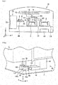
- the component mounting machine 10 is provided with a tray feeder 24, a head unit 12, a moving device 14 that moves the head unit 12, an imaging unit 40 that is applied to the head unit 12, a board conveyor 28, and a control device 50.
- the tray feeder 24 is provided with a housing 23, a tray 22 that stores multiple electronic components 4, and a tray conveyance mechanism 26 that puts in and takes out the tray 22 from the housing 23.
- the housing 23 accommodates multiple trays 22.
- the tray conveyance mechanism 26 moves one of the multiple trays 22 that are accommodated in the housing 23 between a position (suckable position) that is drawn out from the housing 23 and a position (non-suckable position) that is stored in the housing 23.
- the electronic component 4 in the tray 22 that is conveyed to the suckable position is sucked by the head unit 12.
- a tape feeder or the like that accommodates multiple electronic components 4 on a tape may be set as a mechanism that supplies the electronic components 4.
- the moving device 14 moves the head unit 12 in the X-direction and the Y-direction.
- the moving device 14 is constituted by a guide rail that guides the head unit 12, a moving mechanism that moves the head unit 12 along the guide rail, a motor that drives the moving mechanism, and the like.
- the moving device 14 is disposed above the tray 22 and the circuit board 2.
- the head unit 12 moves a cavity above the tray 22 and above the circuit board 2 using the moving device 14.
- the board conveyor 28 is a device that carries out taking in of the circuit board 2 to the component mounting machine 10, positioning at the component mounting position, and taking out from the component mounting machine 10.
- the board conveyor 28 it is possible to constitute the board conveyor 28 using a pair of belt conveyors, a board holding section (not illustrated) that supports the circuit board 2 from below while attached to the belt conveyors, and a driving device that drives the belt conveyors.
- the head unit 12 is provided with a transfer head 16, and a first suction nozzle 20 and a second suction nozzle 120 that are attached to the transfer head 16.
- the first suction nozzle 20 is disposed spaced apart in the X-direction with respect to the second suction nozzle 120.
- the first suction nozzle 20 will be described in detail since the first suction nozzle 20 and the second suction nozzle 120 have the same configuration.
- the first suction nozzle 20 is attached to the transfer head 16 that is movable in the up-down direction (Z-direction in the drawings).
- the first suction nozzle 20 ascends or descends in the up-down direction due to an actuator (not illustrated) that is accommodated in the transfer head 16, or is configured to be able to suck the electronic component 4.
- the first suction nozzle 20 is moved downward until a lower face (suction surface) of the first suction nozzle 20 abuts with the electronic component 4 that is stored in the tray 22.
- the electronic component is sucked by the first suction nozzle 20, and the first suction nozzle 20 is moved upward.
- the transfer head 16 is positioned with respect to the circuit board 2 by the moving device 14.
- the electronic component 4 is mounted on the circuit board 2 by lowering the first suction nozzle toward the circuit board 2.
- the imaging unit 40 is attached to the head unit 12. Therefore, when the head unit 12 moves, the imaging unit 40 integrally moves with the head unit 12.
- the imaging unit 40 is provided with a camera moving device 44, a first camera 42, and a second camera 142.
- the first camera 42 and the second camera 142 are attached to the camera moving device 44.
- the camera moving device 44 is attached to the head unit 12, and the first camera 42 and the second camera 142 are moved in the Y-direction and the Z-direction relatively to the head unit 12.
- the first camera 42 and the second camera 142 are disposed lined up in the X-direction.
- the first camera 42 is disposed at the side of the first suction nozzle 20 (Y-direction in the drawings), and the second camera 142 is disposed at the side of the second suction nozzle 120 (Y-direction in the drawings) .
- the first camera 42 and the second camera 142 are attached to the camera moving device 44 such that the positions of the first camera 42 in the Y-direction and the Z-direction are set to be the same as the respective positions of the second camera 142 in the Y-direction and the Z-direction.
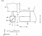
- the first suction nozzle 20 is provided with a first mirror 32 above an electronic component suction surface 20a.
- the first mirror 32 converts an optical path L1 of light that is reflected from the upper face of the electronic component 4 to an optical path L1' at the side of the first suction nozzle 20 (Y-direction in the drawings).
- the first mirror 32 converts an optical path L2 of light from the upper face of the circuit board 2 to an optical path L2' at the side of the first suction nozzle 20 (Y-direction in the drawings) .
- a prism or the like may be used as means for converting the optical path of the light that is reflected from the upper face of the electronic component 4.
- the first camera 42 is disposed at the side of the first suction nozzle 20. Therefore, it is possible for the first camera 42 to receive light from the upper face of the electronic component 4 and light from the upper face of the circuit board 2. That is, it is possible to image the upper face of the electronic component 4 and the upper face of the circuit board 2.
- the second suction nozzle 120 is provided with a second mirror 132 in the same manner as the first suction nozzle 20, and it is possible for the second suction nozzle 120 to receive light from the upper face of the electronic component 4 and light from the upper face of the circuit board 2 that are changed in the optical path by the second mirror 132.
- the imaging region of the first camera 42 is moved in a horizontal direction (Y-direction) with respect to the electronic component 4 and the circuit board 2 when the first camera 42 moves in the up-down direction (Z-direction). Accordingly, it is possible to adjust the positions of the electronic component 4 and the circuit board 2 within the image that is imaged by the first camera 42, by moving the first camera 42 in the up-down direction (Z-direction). In addition, an optical path length from the first camera 42 to the electronic component 4 and the circuit board 2 is changed when the first camera 42 moves in the horizontal direction (Y-direction).
- a width of an imaging region R1 of the first camera 42 in the Y-direction may be smaller than a width of the upper face of the electronic component 4 in the Y-direction.
- a component mark 4a is not positioned inside the imaging region R1 of the first camera 42 when the first camera 42 is positioned at a suitable position. It is possible to image the entire region of the imaging region R1 by moving the first camera 42 in the up-down direction.
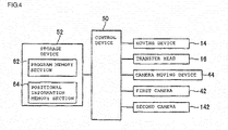
- the control device 50 is configured using a computer that is provided with a CPU, a ROM, and a RAM. As shown in Fig. 4 , the moving device 14, the transfer head 16, the camera moving device 44, the first camera 42, and the second camera 142 are connected to able to communicate with the control device 50.
- the control device 50 mounts the electronic component 4 on the circuit board 2 using the captured image data that is acquired by the imaging unit 40 while controlling operation of each section (14, 16, 44, 42, 142, and the like).
- a storage device 52 is connected to be able to communicate with the control device 50.
- the storage device 52 stores a program memory section 62 that stores a program for controlling the operation of the component mounting machine 10 and a positional information memory section 64 that stores positional information p 1 (x 1 , y 1 ) of the component mark 4a of the electronic component 4 and positional information q 1 (x 2 , y 2 ) of the board mark 2a of the circuit board 2.
- the control device 50 controls the operation of each part (14, 16, 44, 42, 142, and the like) of the component mounting machine 10 based on the program that is stored in the program memory section 62.
- multiple types of electronic components 4 are mounted on the circuit board 2.
- positional information p 1 (x 1 , y 1 ) of the component mark 4a of the electronic components 4 in each type of electronic component is stored in the positional information memory section 64.
- the positional information p 1 (x 1 , y 1 ) of the component mark 4a is coordinate information (positional information at reference coordinates that are set on the electronic component suction surface of the suction nozzle) of the component mark 4a when the electronic component 4 is suitably sucked by the suction nozzles 20 and 120.
- suitable suction refers to a state in which a center point of the electronic component suction surface 20a and a center point of the electronic component 4 overlap when the suction nozzle 20 sucks the electronic component 4.
- the positional information p 1 (x 1 , y 1 ) of the positional information memory section 64 may be acquired by subjecting the captured image data that is acquired by the imaging unit 40 to image processing, and may acquire in advance from design data of the electronic component 4.
- the positional information q 1 (x 2 , y 2 ) of the board mark 2a of the circuit board 2 is stored in advance in the positional information memory section 64.
- step S12 the control device 50 receives the positional information p 1 (x 1 , y 1 ) which relates to the component mark 4a of the electronic component 4 from the storage device 52 according to the type of electronic component 4 that is sucked by the first suction nozzle 20. That is, the type of the electronic component 4 that is stored in each of the multiple trays 22 is known. Therefore, first, the control device 50 specifies the type of the electronic component 4 that is sucked by the first suction nozzle 20 according to the tray 22 that is drawn out by the tray feeder 24. Next, the control device 50 reads the positional information p 1 (x 1 , y 1 ) of the electronic component 4 of the specified type from the storage device 52. Note that, the positional information p 1 (x 1 , y 1 ) is coordinate information of the component mark 4a when the electronic component 4 is suitably sucked by the first suction nozzle 20.
- step S14 the control device 50 sucks the electronic component 4 on the tray 22 using the first suction nozzle 20.
- step S16 the control device 50 starts driving of the moving device 14 and to move the head unit 12, and causes the first suction nozzle 20 that sucks the electronic component 4 to move above the circuit board 2.
- step S18 the control device 50 causes the first camera 42 to move in the up-down direction by driving the camera moving device 44 based on the positional information p 1 (x 1 , y 1 ) that is received in step S12.
- the control device 50 performs processes S18 to S22 from the start of movement by the head unit 12 using the process of S16 until movement by the head unit 12 upwards of the circuit board 2.
- the control device 50 causes the first camera 42 to move in the up-down direction (Z-direction) such that a point designated by the positional information p 1 (x 1 , y 1 ) on the upper face of the electronic component 4 is set in the imaging region R1 of the first camera 42.
- the imaging region R1 of the first camera 42 is moved in a horizontal direction (Y-direction) with respect to the electronic component 4 when the first camera 42 is moved in the up-down direction (Z-direction) .
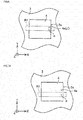
- a state is set in which the component mark 4a of the electronic component 4 is set in the imaging region R1 of the first camera 42 (state indicated in Fig. 6 ) or a state is set in which the component mark 4a of the component mark 4 is positioned around the imaging region R1 of the first camera 42 (state indicated in Fig. 7(A) ) by moving the first camera 42 in the up-down direction (Z-direction) based on the positional information p 1 (x 1 , y 1 ).
- the positional information p 1 (x 1 , y 1 ) indicates a position of the component mark 4a when the electronic component 4 is suitably sucked by the first suction nozzle 20. Therefore, the position of the component mark 4a within the imaging region R1 changes according to the suction state of the electronic component 4 to the first suction nozzle 20. Meanwhile, deviation of the suction position of the electronic component 4 with respect to the first suction nozzle 20 is not deviated so greatly. As a result, a state is set in which the component mark 4a of the electronic component 4 is set in the imaging region R1 of the first camera 42 or a state is set in which the component mark 4a of the component mark 4 is positioned around the imaging region R1 of the first camera 42.
- step S20 the control device 50 determines whether or not the component mark 4a of the electronic component 4 is present in the imaging region R1 of the first camera 42.
- step S22 is skipped and the process proceeds to step S24.
- a case where the component mark 4a is present in the imaging region R1 (YES in S20) is a case where the positional information p 1 (x 1 , y 1 ) of the component mark 4a and an actual position p 2 (x 3 , y 3 ) of the component mark 4a are approximately equal.
- the control device 50 stores the actual position p 2 (x 3 , y 3 ) of the component mark 4a in the storage device 52.
- the control device 50 in a case where the component mark 4a is not present in the imaging region R1 (NO in S20), and the process proceeds to step S22.
- a case where the component mark 4a is not present in the imaging region R1 is a case where the positional information p 1 (x 1 , y 1 ) and the actual position p 2 (x 3 , y 3 ) are largely deviated, for example, when the electronic component 4 is sucked by the first suction nozzle 20.
- the component mark 4a is present outside of the region of the imaging region R1 even if the imaging region R1 of the first camera 42 is positioned based on the positional information p 1 (x 1 , y 1 ).
- step S22 the control device 50 positions the component mark 4a of the electronic component 4 in the imaging region R1 of the first camera 42. Specifically, the control device 50 searches for the component mark 4a and positions the component mark 4a in the imaging region R1 of the first camera 42 by moving the first camera 42 in the up-down direction (Z-direction) and moving the imaging region R1 of the first camera 42 in the horizontal direction (Y-direction) with respect to the electronic component 4 (for example, a state indicated in Fig. 7(B) ).
- the control device 50 stores the actual position p 2 (x 3 , y 3 ) of the component mark 4a in the storage device 52.
- the control device 50 inspects the surface state of the electronic component 4 using the captured image data of the first camera 42 while the head unit 12 moves toward the circuit board 2 (S16 to S22). As a result, it is possible to suppress mounting of the electronic component 4 with an abnormality on the surface on the circuit board 2.
- step S24 the control device 50 calculates a difference value W of positions in the X-direction and a difference value H of positions in the Y-direction of the component mark 4a and the board mark 2a based on the actual position p 2 (x 3 , y 3 ) of the component mark 4a and the positional information q 1 (x 2 , y 2 ) of the board mark 2a.
- the difference value W is a difference value of x 3 and x 2
- the difference value H is a difference value of y 3 and y 2 .
- step S26 the control device 50 determines whether or not it is possible to position both the component mark 4a and the board mark 2a in the imaging region R1 of the first camera 42.
- the control device 50 proceeds to step S28 in a case where it is possible to position both the component mark 4a and the board mark 2a in the imaging region R1 (YES in S26).
- the control device 50 proceeds to step S32 in a case where it is not possible to position both the component mark 4a and the board mark 2a in the imaging region R1 (NO in S26).
- a case where it is not possible to position both the component mark 4a and the board mark 2a in the imaging region R1 is a case where the difference value W is larger than the width of the imaging region R1 in the X-direction or the difference value H is larger than the width of the imaging region R1 in the Y-direction.
- step S28 the control device 50 causes the first camera 42 to move in the up-down direction (Z-direction) and/or the head unit 12 on the horizontal plane (X-direction and/or Y-direction) such that the position of the center point of the imaging region R1 of the first camera 42 and the position of the center point of the component mark 4a and the board mark 2a overlap (state indicated in Fig. 7(D) ).
- the control device 50 causes the first camera 42 to move in the up-down direction (Z-direction) and/or the head unit 12 on the horizontal plane (X-direction and/or Y-direction) such that the position of the center point of the imaging region R1 of the first camera 42 and the position of the center point of the component mark 4a and the board mark 2a overlap (state indicated in Fig. 7(D) ).
- the board mark 2a tends not to come away from the imaging region R1 more in a case where the circuit board 2 moves in a right direction with respect to the electronic component 4 from the state in Fig. 7(D) than in a case where the circuit board 2 moves in the right direction with respect to the electronic component 4 from the state in Fig.7(C) .
- step S30 the control device 50 mounts the electronic component 4 on the circuit board 2. Specifically, first, the control device 50 determines the mounting position of the electronic component 4 from a relative position of the component mark 4a and the board mark 2a that is positioned in the imaging region R1. Next, the control device 50 finely adjusts the first suction nozzle 20 in the X-direction and the Y-direction based on the determined mounting position. The control device 50 lowers the first suction nozzle 20 using the transfer head 16 and mounts the electronic component 4 on the circuit board 2 if the first suction nozzle 20 is moved to the mounting position.
- step S32 the control device 50 repositions the component mark 4a of the electronic component 4 in the imaging region R1 of the first camera 42.
- the control device 50 adjusts such that the component mark 4a is positioned within the imaging region R1 by moving the first camera 42 in the up-down direction (Z-direction) and moving the imaging region R1 of the first camera 42 in the horizontal direction (Y-direction) with respect to the circuit board 2.
- the actual position p 2 (x 3 , y 3 ) of the component mark 4a is acquired while the transfer head 16 moves.
- the control device 50 updates the actual position p 2 (x 3 , y 3 ) that is stored in the storage device 52 of the component mark 4a to the actual position p 3 (x 4 , y 4 ).
- step S34 the control device 50 positions the board mark 2a of the circuit board 2 in the imaging region R1 of the first camera 42.
- the control device 50 adjusts such that the board mark 2a is positioned within the imaging region R1 by moving the first camera 42 in the up-down direction (Z-direction) and moving the imaging region R1 of the first camera 42 in the horizontal direction (Y-direction) with respect to the circuit board 2.
- the control device 50 stores the actual position q 2 (x 5 , y 5 ) of the board mark 2a in the storage device 52.
- step S36 the control device 50 mounts the electronic component 4 on the circuit board 2. Specifically, the control device 50 determines the mounting position of the electronic component 4 based on the actual position p 3 (x 4 , y 4 ) of the component mark 4a and the actual position q 2 (x 5 , y 5 ) of the board mark 2a that are stored in the storage device 52. The control device 50 lowers the first suction nozzle 20 using the transfer head 16 and mounts the electronic component 4 on the circuit board 2 if the first suction nozzle 20 is moved to the mounting position. It is possible to omit the process of S32 since the control device 50 shortens the time that is necessary for mounting of the electronic component 4 on circuit board 2.
- control device 50 determines the mounting position of the electronic component 4 based on the actual position p 2 (x 3 , y 3 ) of the component mark 4a and the actual position q 2 (x 5 , y 5 ) of the board mark 2a.
- the description above relates only to positioning processing that uses the first suction nozzle 20 and the first camera 42, but the second suction nozzle 120 and the second camera 142 perform the same processes.
- the component mounting machine 10 of the present embodiment it is possible to move the position of the first camera 42 based on the positional information p 1 (x 1 , y 1 ) of the component mark 4a of the electronic component 4 that is stored in the positional information memory section 64. It is possible to position the component mark 4a in the imaging region R1 by further moving the first camera 42 when the component mark 4a is not positioned within the imaging region R1 of the first camera 42. When configuring in this manner, it is possible to shorten the time that is necessary in positioning of the component mark 4a in the imaging region R1 and it is possible to reliably position the component mark 4a in the imaging region R1.
- the head unit 212 is provided with the transfer head 16, and four suction nozzles 220, 222, 224, and 226 that are attached to the transfer head 16.
- the suction nozzle 222 is disposed spaced apart in the Y-direction with respect to the suction nozzle 220.
- the suction nozzle 226 is disposed spaced apart in the X-direction with respect to the suction nozzle 220.
- the suction nozzle 224 is disposed spaced apart in the X-direction and the Y-direction with respect to the suction nozzle 220.
- the suction nozzle 224 is attached to the transfer head 16 such that the position of the suction nozzle 224 in the Y-direction is the same position as the suction nozzle 222 in the Y-direction.
- the position of the suction nozzle 224 in the X-direction is attached to the transfer head 16 so as to be the same position as the suction nozzle 226 in the X-direction.
- the suction nozzle 220 and the suction nozzle 226 have the same configuration.
- the suction nozzle 222 and the suction nozzle 224 have the same configuration.
- Each suction nozzle is attached to the transfer head 16 that is movable in the up-down direction (Z-direction in the drawings). Each suction nozzle is independently movable in the up-down direction.
- the suction nozzle 220 is provided with a mirror 230 above a suction surface 220a.
- the mirror 230 converts light from the upper face of the electronic component 4 that is sucked to the suction surface 220a in the Y-direction.
- the suction nozzle 222 is provided with a mirror 232 above a suction surface 222a.
- the mirror 232 converts the optical path of light from the upper face of the electronic component 4 that is sucked by the suction surface 222a in the X-direction.
- the imaging unit 240 is attached to an imaging unit holding section 250.
- the imaging unit holding section 250 is disposed adjacent to the tray feeder 24 in the X-direction.
- the imaging unit holding section 250 is disposed adjacent to the board conveyor 28 in the Y-direction.
- the imaging unit 240 is provided with a first camera 242 and a second camera 244. Note that, it is possible for the moving device 14 to move the head unit 12 relatively to the imaging unit 240.
- the first camera 242 is spaced apart in the X-direction with respect to the suction nozzle 222, and the tray feeder 24 and the imaging unit holding section 250 are disposed lined up at the imaging unit holding section 250 side.
- the first camera 242 is able to receive light that is changed in the optical path by the mirrors 232 and 234.
- the second camera 244 is spaced apart in the Y-direction with respect to the suction nozzle 226, and the board holding section 200 and the imaging unit holding section 250 are disposed lined up at the imaging unit holding section 250 side. Therefore, the second camera 244 is able to receive light that is changed in the optical path by the mirrors 230 and 236.
- the control device 50 adjusts the position of the suction nozzle 224 in the Y-direction so as to be the same as the position of the first camera 242 in the Y-direction and the position of the suction nozzle 226 in the X-direction so as to be the same as the position of the second camera 244 in the X-direction by driving the moving device 14 and moving the head unit 12 on the horizontal plane (X-direction and/or Y-direction).
- the transfer head 16 moves the suction nozzle 222 in the Z-direction, and adjusts the position at which the suction nozzle 222 does not hinder the optical path of the light that is changed in the optical path using the mirror 234.
- the first camera 242 is able to receive light that is changed in the optical path using the mirror 234 and the second camera 244 is able to receive light that is changed in the optical path using the mirror 236. That is, the first camera 242 images the electronic component 4 and the circuit board 2 that are sucked by the suction nozzle 224 and the second camera 244 images the electronic component 4 and the circuit board 2 that are sucked by the suction nozzle 226.
- the control device 50 adjusts the position of the suction nozzle 220 in the X-direction so as to be the same as the position of the second camera 244 in the X-direction by driving the moving device 14 and moving the head unit 12 on the horizontal plane (X-direction and/or Y-direction).
- the transfer head 16 adjusts the position of the suction nozzle 222 in the Z-direction so as to be the same as the position of the first camera 242 in the Z-direction by moving the suction nozzle 222 in the Z-direction.
- the first camera 242 is able to receive light that is changed in the optical path using the mirror 232 and the second camera 244 is able to receive light that is changed in the optical path using the mirror 230.
- the first camera 242 images the electronic component 4 and the circuit board 2 that are sucked by the suction nozzle 222 and the second camera 244 images the electronic component 4 and the circuit board 2 that are sucked by the suction nozzle 224.
- the transfer head 16 is moved on the horizontal plane, the suction nozzle moves to the mounting position on the circuit board 2, and the electronic component 4 that is sucked by the suction nozzle is mounted.
- the transfer head 16 does not interfere with the cameras 242 and 244 when entering/exiting the imaging region of the cameras 242 and 244 since the first camera 242 and the second camera 244 of the imaging unit 240 are installed at the opposite side from the imaging unit holding section 250. Accordingly, the transfer head 16 may move only horizontally without there being a need to retreat in the up-down direction when entering/exiting the imaging region of the cameras 242 and 244.
- the positional information p 1 (x 1 , y 1 ) of the component mark 4a of the electronic components 4 is stored in advance in the storage device 52.
- the positional information p 1 (x 1 , y 1 ) that is stored in the storage device 52 may be corrected using the actual position p 2 (x 3 , y 3 ) or the actual position p 3 (x 4 , y 4 ).
Landscapes
- Engineering & Computer Science (AREA)
- Microelectronics & Electronic Packaging (AREA)
- Manufacturing & Machinery (AREA)
- Operations Research (AREA)
- Theoretical Computer Science (AREA)
- Physics & Mathematics (AREA)
- General Physics & Mathematics (AREA)
- Computer Vision & Pattern Recognition (AREA)
- Multimedia (AREA)
- Signal Processing (AREA)
- Quality & Reliability (AREA)
- Supply And Installment Of Electrical Components (AREA)
- Image Input (AREA)
Abstract
Description
- A technique that is disclosed in the present description relates to a technique for positioning of a component mounting machine that mounts an electronic component on a circuit board.
- A mounting device that positions a chip that is given a recognition mark for positioning and a board that is given a recognition mark for positioning is disclosed in PTL 1 (International Publication No.
2003/041478 ). The mounting device in PTL 1 is provided with a tool that sucks the chip, a prism that converts an optical path of light from each recognition mark for positioning in the tool to the side of the tool, and recognition means that receives light of which the optical path is changed using the prism. Positioning of the chip and the board is performed by recognizing the recognition mark for positioning of the chip and the recognition mark for positioning of the board using the recognition means. - In the component mounting machine, multiple types of electronic components are mounted on the circuit board. When the types of electronic components are different from each other, the positions of the recognition marks for positioning that are given to the electronic components may be different from each other since the sizes or shapes of the electronic components are different from each other. In the mounting device in PTL 1, a case where the positions of the recognition marks for positioning that are given to the electronic components are different from each other is not assumed, it is necessary to adjust the position of a camera such that the recognition marks for positioning that are applied to the electronic components are positioned inside an imaging region of the camera when the recognition marks for positioning that are given to the electronic components are not present in the image that is imaged by the camera. When the position of the camera is adjusted, there is a problem in that mounting efficiency of the electronic components is low since time for adjustment is necessary.
- A component mounting machine that is disclosed in the present description mounts components having a component mark for positioning on an upper face on a circuit board. The component mounting machine has a first suction nozzle that is provided with a suction surface that sucks the upper face of the component, a transfer head that supports the first suction nozzle and mounts the component that is sucked by the first suction nozzle on the circuit board by moving the first suction nozzle relatively to the circuit board, optical path conversion means that is disposed above the suction surface and converts an optical path of light from the upper face of the component to the side, a first camera that is disposed at a position at which it is possible to receive, from the upper face of the component, light which is changed in the optical path by the optical path conversion means, a camera moving device that moves the first camera relatively to the first suction nozzle, and a control device that controls operation of the transfer head and the camera moving device. The camera moving device moves the first camera in at least a first direction that is orthogonal to an optical axis of the first camera, and an imaging region of the first camera moves in a second direction with respect to the center of the component when the first camera moves in the first direction. The control device is provided with a memory section that stores in advance positional information of a component mark, causes the first suction nozzle to suck the component, and causes the first camera to move by the camera moving device based on the positional information within the memory section.
- In the component mounting machine, the control device is able to cause the first camera to move based on positional information of the component mark since the positional information of the component mark is stored in the memory section. When configuring in this manner, it is possible to shorten the time that is necessary for setting the component mark in the imaging region of the camera even in a case where the position of the component mark in each type of component is different from each other.
-
- [
Fig. 1] Fig. 1 is a side view schematically illustrating a configuration of a component mounting machine of a first embodiment. - [
Fig. 2] Fig. 2 is a perspective view illustrating a configuration of a head unit and an imaging unit of the first embodiment. - [
Fig. 3] Fig. 3 is a side view illustrating a configuration of the head unit and the imaging unit of the first embodiment. - [
Fig. 4] Fig. 4 is a block diagram illustrating a configuration of a control system of the component mounting machine of the first embodiment. - [
Fig. 5] Fig. 5 is a flowchart illustrating positioning processing of the component mounting machine. - [
Fig. 6] Fig. 6 is a diagram illustrating an example of a state in which a component mark is set in an imaging region of a first camera in a case where the first camera is positioned based on positional information within a memory section. - [
Fig. 7A] Fig. 7A is a diagram illustrating an example of a state in which the component mark is not set in the imaging region of the first camera in a case where the first camera is positioned based on the positional information within the memory section. - [
Fig. 7B] Fig. 7B is a diagram illustrating an example of a state in which the first camera is positioned such that the component mark is set in the imaging region of the first camera. - [
Fig. 7C] Fig. 7C is a diagram illustrating an example of a state in which the first camera is positioned such that a board mark is set in the imaging region of the first camera. - [
Fig. 7D] Fig. 7D is a diagram illustrating an example of a state in which the first camera is positioned such that a center point of the component mark and the board mark and a center point of the imaging region of the first camera overlap. - [
Fig. 8] Fig. 8 is a perspective view illustrating a configuration of a head unit and an imaging unit of a second embodiment. - [
Fig. 9] Fig. 9 is a top view schematically illustrating a configuration in the second embodiment. - Key features of an embodiment that will be described below are listed. Note that, technical elements that will be described below are technical elements that are independent of each other, exhibit technical usefulness using one or various combinations, but are not limited to the combination as claimed at the time of filing.
- (Feature 1) A control device may position a component mark within an imaging region of a first camera by further moving the first camera using a camera moving device when the component mark is not positioned within the imaging region of the first camera in a case where the component is sucked by a first suction nozzle and the first camera is moved by the camera moving device based on positional information within a memory section. When configuring in this manner, it is possible to position the component mark within the imaging region of the first camera even when the component mark is not positioned within the imaging region of the first camera in a case where the first camera is moved based on positional information within a memory section.
- (Feature 2) The first camera may be disposed on an optical path that is changed by the optical path conversion means, the camera moving device may move the first camera in at least an up-down direction with respect to the first suction nozzle, and the imaging region of the first camera may move in a direction that is parallel to the optical path that is changed by the optical path conversion means with respect to the center of the component when the first camera moves in the up-down direction. The control device may causes suction nozzle to suck the component, and may cause the first camera to move in the up-down direction by the camera moving device based on the positional information within the memory section. When configuring in this manner, it is possible to adjust the imaging region of the first camera by moving the first camera in the up-down direction since light that is changed in the optical path by the optical path conversion means is imaged by the first camera.
- (Feature 3) The control device may position the component mark within the imaging region of the first camera by further moving the first camera in the up-down direction using the camera moving device when the component mark is not positioned within the imaging region of the first camera in a case where the component is sucked by the first suction nozzle and the first camera is moved by the camera moving device based on positional information within the memory section. When configuring in this manner, it is possible to position the component mark within the imaging region of the first camera even when the component mark is not positioned within the imaging region of the first camera.
- (Feature 4) A circuit board may have a board mark for positioning, the optical path conversion means may convert an optical path of light from the upper face of the circuit board to the side, and the first camera may be disposed at a position at which it is possible to receive, from the upper face of the circuit board, light that is changed in the optical path by the optical path conversion means. The control device may determine the mounting position of the component on the circuit board based on the relative positions of the component mark and the board mark that are imaged by the first camera. When configuring in this manner, it is possible to determine the mounting position of the component on the circuit board based on the relative position of the component mark and the board mark that are imaged by the first camera. Therefore, it is possible to improve accuracy of positioning of the component and the circuit board.
- (Feature 5) The control device may position both of the component mark and the board mark within the imaging region of the first camera by moving the first camera using the camera moving device. When configuring in this manner, it is possible to position the component and the circuit board in a state in which the component mark and the board mark are imaged by the first camera. Therefore, it is possible to improve accuracy of positioning of the component and the circuit board.
- (Feature 6) The control device may position the imaging region of the first camera such that the center point of the imaging region of the first camera and the center point of the component mark and the board mark overlap by moving the first camera using the camera moving device. When configuring in this manner, it is possible to prevent the board mark or the component mark from coming away from the imaging region of the first camera when the component or the circuit board is moved to the mounting position. Therefore, there is a high possibility that it is possible to position the component and the circuit board at the mounting position in a state in which the component mark and the board mark are imaged by the first camera. As a result, it is possible to improve mounting accuracy of the component on the circuit board.
- (Feature 7) The component mounting machine may further have a second suction nozzle that is provided with a suction surface that sucks the upper face of the component and optical path conversion means that is disposed above the suction surface and converts the optical path of the light from the upper face of the component to the side, and a second camera that is disposed at a position at which it is possible to receive light, from the upper face of the component that is sucked by the second suction nozzle, which is changed in the optical path by the optical path conversion means of the second suction nozzle. The transfer head may support the first suction nozzle and the second suction nozzle and mount the component that is sucked by the first suction nozzle and the second suction nozzle on the circuit board by moving the first suction nozzle and the second suction nozzle relatively to the circuit board, the first camera and the second camera may be disposed such that the optical axis of the first camera and the optical axis of the second camera are parallel, and the camera moving device may relatively move each of the first camera and the second camera in a direction that is orthogonal to the optical axis with respect to the first suction nozzle and the second suction nozzle. The control device may control the operation of the transfer head and the camera moving device based on captured image data of the first camera and captured image data of the second camera. When configuring in this manner, it is possible to simultaneously suck and image two components. Thereby, it is possible to shorten the time that is necessary for mounting of the component on the circuit board.
- (Feature 8) The first camera, the second camera, and the camera moving device may be attached to the transfer head and relatively move integrally with the transfer head with respect to the circuit board. The control device may inspect a surface state of each component that is sucked by the first suction nozzle and the second suction nozzle by using the captured image data of the first camera and the captured image data of the second camera after a component is sucked by each of the first suction nozzle and the second suction nozzle until mounting the component on the circuit board in a case where the component is sucked by each of the first suction nozzle and the second suction nozzle and is mounted on the circuit board. When configuring in this manner, if the component is sucked by each of the first suction nozzle and the second suction nozzle, it is possible to image the component, which is sucked by each of the first suction nozzle and the second suction nozzle, using the first camera and the second camera. Thereby, it is possible to inspect the surface state of each component using the captured image data of the first camera and the second camera prior to mounting each of the components on the circuit board. As a result, it is possible to suppress mounting of the component on the circuit board that is abnormal in the surface state.
- (First Embodiment) A
component mounting machine 10 according to a first embodiment will be described below. Thecomponent mounting machine 10 is a device that mounts anelectronic component 4 on acircuit board 2. Thecomponent mounting machine 10 is referred to as a surface mounting machine, a chip mounter, or the like. Thecomponent mounting machine 10 is placed next to a solder printing machine, another component mounting machine, and a board inspection machine, and is constituted by a mounting line in series. - As shown in
Fig. 1 , thecomponent mounting machine 10 is provided with atray feeder 24, ahead unit 12, a movingdevice 14 that moves thehead unit 12, animaging unit 40 that is applied to thehead unit 12, aboard conveyor 28, and acontrol device 50. Thetray feeder 24 is provided with ahousing 23, atray 22 that stores multipleelectronic components 4, and atray conveyance mechanism 26 that puts in and takes out thetray 22 from thehousing 23. Thehousing 23 accommodatesmultiple trays 22. Thetray conveyance mechanism 26 moves one of themultiple trays 22 that are accommodated in thehousing 23 between a position (suckable position) that is drawn out from thehousing 23 and a position (non-suckable position) that is stored in thehousing 23. Theelectronic component 4 in thetray 22 that is conveyed to the suckable position is sucked by thehead unit 12. A tape feeder or the like that accommodates multipleelectronic components 4 on a tape may be set as a mechanism that supplies theelectronic components 4. - The moving
device 14 moves thehead unit 12 in the X-direction and the Y-direction. The movingdevice 14 is constituted by a guide rail that guides thehead unit 12, a moving mechanism that moves thehead unit 12 along the guide rail, a motor that drives the moving mechanism, and the like. The movingdevice 14 is disposed above thetray 22 and thecircuit board 2. Thehead unit 12 moves a cavity above thetray 22 and above thecircuit board 2 using the movingdevice 14. - The
board conveyor 28 is a device that carries out taking in of thecircuit board 2 to thecomponent mounting machine 10, positioning at the component mounting position, and taking out from thecomponent mounting machine 10. For example, it is possible to constitute theboard conveyor 28 using a pair of belt conveyors, a board holding section (not illustrated) that supports thecircuit board 2 from below while attached to the belt conveyors, and a driving device that drives the belt conveyors. - As shown in
Figs. 1 and 2 , thehead unit 12 is provided with atransfer head 16, and afirst suction nozzle 20 and asecond suction nozzle 120 that are attached to thetransfer head 16. Thefirst suction nozzle 20 is disposed spaced apart in the X-direction with respect to thesecond suction nozzle 120. Here, thefirst suction nozzle 20 will be described in detail since thefirst suction nozzle 20 and thesecond suction nozzle 120 have the same configuration. Thefirst suction nozzle 20 is attached to thetransfer head 16 that is movable in the up-down direction (Z-direction in the drawings). Thefirst suction nozzle 20 ascends or descends in the up-down direction due to an actuator (not illustrated) that is accommodated in thetransfer head 16, or is configured to be able to suck theelectronic component 4. First, in mounting of theelectronic component 4 on thecircuit board 2 by thetransfer head 16, thefirst suction nozzle 20 is moved downward until a lower face (suction surface) of thefirst suction nozzle 20 abuts with theelectronic component 4 that is stored in thetray 22. Next, the electronic component is sucked by thefirst suction nozzle 20, and thefirst suction nozzle 20 is moved upward. Next, thetransfer head 16 is positioned with respect to thecircuit board 2 by the movingdevice 14. Next, theelectronic component 4 is mounted on thecircuit board 2 by lowering the first suction nozzle toward thecircuit board 2. - The
imaging unit 40 is attached to thehead unit 12. Therefore, when thehead unit 12 moves, theimaging unit 40 integrally moves with thehead unit 12. Theimaging unit 40 is provided with acamera moving device 44, afirst camera 42, and asecond camera 142. Thefirst camera 42 and thesecond camera 142 are attached to thecamera moving device 44. Thecamera moving device 44 is attached to thehead unit 12, and thefirst camera 42 and thesecond camera 142 are moved in the Y-direction and the Z-direction relatively to thehead unit 12. Thefirst camera 42 and thesecond camera 142 are disposed lined up in the X-direction. Thefirst camera 42 is disposed at the side of the first suction nozzle 20 (Y-direction in the drawings), and thesecond camera 142 is disposed at the side of the second suction nozzle 120 (Y-direction in the drawings) . Thefirst camera 42 and thesecond camera 142 are attached to thecamera moving device 44 such that the positions of thefirst camera 42 in the Y-direction and the Z-direction are set to be the same as the respective positions of thesecond camera 142 in the Y-direction and the Z-direction. - Here, an imaging method using the
head unit 12 and theimaging unit 40 will be described usingFig. 3 . As shown inFig. 3 , thefirst suction nozzle 20 is provided with afirst mirror 32 above an electroniccomponent suction surface 20a. Thefirst mirror 32 converts an optical path L1 of light that is reflected from the upper face of theelectronic component 4 to an optical path L1' at the side of the first suction nozzle 20 (Y-direction in the drawings). In addition, thefirst mirror 32 converts an optical path L2 of light from the upper face of thecircuit board 2 to an optical path L2' at the side of the first suction nozzle 20 (Y-direction in the drawings) . In place of the mirror, a prism or the like may be used as means for converting the optical path of the light that is reflected from the upper face of theelectronic component 4. As described above, thefirst camera 42 is disposed at the side of thefirst suction nozzle 20. Therefore, it is possible for thefirst camera 42 to receive light from the upper face of theelectronic component 4 and light from the upper face of thecircuit board 2. That is, it is possible to image the upper face of theelectronic component 4 and the upper face of thecircuit board 2. Note that, thesecond suction nozzle 120 is provided with asecond mirror 132 in the same manner as thefirst suction nozzle 20, and it is possible for thesecond suction nozzle 120 to receive light from the upper face of theelectronic component 4 and light from the upper face of thecircuit board 2 that are changed in the optical path by thesecond mirror 132. - As apparent from
Fig. 3 , the imaging region of thefirst camera 42 is moved in a horizontal direction (Y-direction) with respect to theelectronic component 4 and thecircuit board 2 when thefirst camera 42 moves in the up-down direction (Z-direction). Accordingly, it is possible to adjust the positions of theelectronic component 4 and thecircuit board 2 within the image that is imaged by thefirst camera 42, by moving thefirst camera 42 in the up-down direction (Z-direction). In addition, an optical path length from thefirst camera 42 to theelectronic component 4 and thecircuit board 2 is changed when thefirst camera 42 moves in the horizontal direction (Y-direction). Accordingly, it is possible to match a focus of thefirst camera 42 to theelectronic component 4 and thecircuit board 2 by thefirst camera 42 moving in the horizontal direction (Y-direction). Note that, as shown inFigs. 6 and7 , according to the type of theelectronic component 4, a width of an imaging region R1 of thefirst camera 42 in the Y-direction may be smaller than a width of the upper face of theelectronic component 4 in the Y-direction. In this case, acomponent mark 4a is not positioned inside the imaging region R1 of thefirst camera 42 when thefirst camera 42 is positioned at a suitable position. It is possible to image the entire region of the imaging region R1 by moving thefirst camera 42 in the up-down direction. Therefore, it is possible to position thecomponent mark 4a within the imaging region R1 of thefirst camera 42 even in a case where the width of the imaging region R1 of thefirst camera 42 in the Y-direction is smaller than the width of the upper face of theelectronic component 4 in the Y-direction. - The
control device 50 is configured using a computer that is provided with a CPU, a ROM, and a RAM. As shown inFig. 4 , the movingdevice 14, thetransfer head 16, thecamera moving device 44, thefirst camera 42, and thesecond camera 142 are connected to able to communicate with thecontrol device 50. Thecontrol device 50 mounts theelectronic component 4 on thecircuit board 2 using the captured image data that is acquired by theimaging unit 40 while controlling operation of each section (14, 16, 44, 42, 142, and the like). - In addition, a
storage device 52 is connected to be able to communicate with thecontrol device 50. Thestorage device 52 stores aprogram memory section 62 that stores a program for controlling the operation of thecomponent mounting machine 10 and a positionalinformation memory section 64 that stores positional information p1 (x1, y1) of thecomponent mark 4a of theelectronic component 4 and positional information q1 (x2, y2) of theboard mark 2a of thecircuit board 2. Thecontrol device 50 controls the operation of each part (14, 16, 44, 42, 142, and the like) of thecomponent mounting machine 10 based on the program that is stored in theprogram memory section 62. In thecomponent mounting machine 10 of the present embodiment, multiple types ofelectronic components 4 are mounted on thecircuit board 2. Theelectronic components 4 have different shapes and sizes in each type and have different positions at which thecomponent mark 4a is applied. Therefore, positional information p1 (x1, y1) of thecomponent mark 4a of theelectronic components 4 in each type of electronic component is stored in the positionalinformation memory section 64. Here, for example, the positional information p1 (x1, y1) of thecomponent mark 4a is coordinate information (positional information at reference coordinates that are set on the electronic component suction surface of the suction nozzle) of thecomponent mark 4a when theelectronic component 4 is suitably sucked by thesuction nozzles component suction surface 20a and a center point of theelectronic component 4 overlap when thesuction nozzle 20 sucks theelectronic component 4. In addition, note that, the positional information p1 (x1, y1) of the positionalinformation memory section 64 may be acquired by subjecting the captured image data that is acquired by theimaging unit 40 to image processing, and may acquire in advance from design data of theelectronic component 4. In addition, the positional information q1 (x2, y2) of theboard mark 2a of thecircuit board 2 is stored in advance in the positionalinformation memory section 64. - Next, positioning processing of the
component mark 4a of theelectronic component 4 and theboard mark 2a of thecircuit board 2 that is carried out by thecontrol device 50 will be described usingFigs. 5 to 9 . Note that, since a process for mounting theelectronic component 4 on thecircuit board 2 using thefirst suction nozzle 20 and a process for mounting theelectronic component 4 on thecircuit board 2 using thesecond suction nozzle 120 are the same process, here the process for mounting theelectronic component 4 on thecircuit board 2 using thefirst suction nozzle 20 will be described. - As shown in
Fig. 5 , first, in step S12, thecontrol device 50 receives the positional information p1 (x1, y1) which relates to thecomponent mark 4a of theelectronic component 4 from thestorage device 52 according to the type ofelectronic component 4 that is sucked by thefirst suction nozzle 20. That is, the type of theelectronic component 4 that is stored in each of themultiple trays 22 is known. Therefore, first, thecontrol device 50 specifies the type of theelectronic component 4 that is sucked by thefirst suction nozzle 20 according to thetray 22 that is drawn out by thetray feeder 24. Next, thecontrol device 50 reads the positional information p1 (x1, y1) of theelectronic component 4 of the specified type from thestorage device 52. Note that, the positional information p1 (x1, y1) is coordinate information of thecomponent mark 4a when theelectronic component 4 is suitably sucked by thefirst suction nozzle 20. - Next, in step S14, the
control device 50 sucks theelectronic component 4 on thetray 22 using thefirst suction nozzle 20. Next, in step S16, thecontrol device 50 starts driving of the movingdevice 14 and to move thehead unit 12, and causes thefirst suction nozzle 20 that sucks theelectronic component 4 to move above thecircuit board 2. - Next, in step S18, the
control device 50 causes thefirst camera 42 to move in the up-down direction by driving thecamera moving device 44 based on the positional information p1 (x1, y1) that is received in step S12. Note that, thecontrol device 50 performs processes S18 to S22 from the start of movement by thehead unit 12 using the process of S16 until movement by thehead unit 12 upwards of thecircuit board 2. Thecontrol device 50 causes thefirst camera 42 to move in the up-down direction (Z-direction) such that a point designated by the positional information p1 (x1, y1) on the upper face of theelectronic component 4 is set in the imaging region R1 of thefirst camera 42. As already described, the imaging region R1 of thefirst camera 42 is moved in a horizontal direction (Y-direction) with respect to theelectronic component 4 when thefirst camera 42 is moved in the up-down direction (Z-direction) . A state is set in which thecomponent mark 4a of theelectronic component 4 is set in the imaging region R1 of the first camera 42 (state indicated inFig. 6 ) or a state is set in which thecomponent mark 4a of thecomponent mark 4 is positioned around the imaging region R1 of the first camera 42 (state indicated inFig. 7(A) ) by moving thefirst camera 42 in the up-down direction (Z-direction) based on the positional information p1 (x1, y1). That is, the positional information p1 (x1, y1) indicates a position of thecomponent mark 4a when theelectronic component 4 is suitably sucked by thefirst suction nozzle 20. Therefore, the position of thecomponent mark 4a within the imaging region R1 changes according to the suction state of theelectronic component 4 to thefirst suction nozzle 20. Meanwhile, deviation of the suction position of theelectronic component 4 with respect to thefirst suction nozzle 20 is not deviated so greatly. As a result, a state is set in which thecomponent mark 4a of theelectronic component 4 is set in the imaging region R1 of thefirst camera 42 or a state is set in which thecomponent mark 4a of thecomponent mark 4 is positioned around the imaging region R1 of thefirst camera 42. In the present embodiment, it is possible to position thecomponent mark 4a within the imaging region R1 of thefirst camera 42 for a shorter time than in a case where thefirst camera 42 is moved without using the positional information p1 (x1, y1) by moving thefirst camera 42 using the positional information p1 (x1, y1). - Next, in step S20, the
control device 50 determines whether or not thecomponent mark 4a of theelectronic component 4 is present in the imaging region R1 of thefirst camera 42. In thecontrol device 50, in a case where thecomponent mark 4a is present in the imaging region R1 (YES in S20), step S22 is skipped and the process proceeds to step S24. As shown inFig. 6 , a case where thecomponent mark 4a is present in the imaging region R1 (YES in S20) is a case where the positional information p1 (x1, y1) of thecomponent mark 4a and an actual position p2 (x3, y3) of thecomponent mark 4a are approximately equal. Thecontrol device 50 stores the actual position p2 (x3, y3) of thecomponent mark 4a in thestorage device 52. In thecontrol device 50, in a case where thecomponent mark 4a is not present in the imaging region R1 (NO in S20), and the process proceeds to step S22. A case where thecomponent mark 4a is not present in the imaging region R1 is a case where the positional information p1 (x1, y1) and the actual position p2 (x3, y3) are largely deviated, for example, when theelectronic component 4 is sucked by thefirst suction nozzle 20. In a case where deviation width in the Y-direction of the positional information p1 (x1, y1) and the actual position p2 (x3, y3) is larger than the width of the imaging region R1 in the Y-direction, thecomponent mark 4a is present outside of the region of the imaging region R1 even if the imaging region R1 of thefirst camera 42 is positioned based on the positional information p1 (x1, y1). - Next, in step S22, the
control device 50 positions thecomponent mark 4a of theelectronic component 4 in the imaging region R1 of thefirst camera 42. Specifically, thecontrol device 50 searches for thecomponent mark 4a and positions thecomponent mark 4a in the imaging region R1 of thefirst camera 42 by moving thefirst camera 42 in the up-down direction (Z-direction) and moving the imaging region R1 of thefirst camera 42 in the horizontal direction (Y-direction) with respect to the electronic component 4 (for example, a state indicated inFig. 7(B) ). Thereby, it is possible to reliably position thecomponent mark 4a within the imaging region R1 even in a case where the positional information p1 (x1, y1) of thecomponent mark 4a and the actual position p2 (x3, y3) of thecomponent mark 4a that are received from thestorage device 52 are different from each other. In addition, a difference between the positional information p1 (x3, y1) and the actual position p2 (x3, y3) is often very small in a case where thefirst suction nozzle 20 or thecamera moving device 44 is normal. Therefore, it is possible to end the process of S22 in a short time. Thecontrol device 50 stores the actual position p2 (x3, y3) of thecomponent mark 4a in thestorage device 52. In addition, thecontrol device 50 inspects the surface state of theelectronic component 4 using the captured image data of thefirst camera 42 while thehead unit 12 moves toward the circuit board 2 (S16 to S22). As a result, it is possible to suppress mounting of theelectronic component 4 with an abnormality on the surface on thecircuit board 2. - Next, in step S24, the
control device 50 calculates a difference value W of positions in the X-direction and a difference value H of positions in the Y-direction of thecomponent mark 4a and theboard mark 2a based on the actual position p2 (x3, y3) of thecomponent mark 4a and the positional information q1 (x2, y2) of theboard mark 2a. The difference value W is a difference value of x3 and x2, and the difference value H is a difference value of y3 and y2. Next, in step S26, thecontrol device 50 determines whether or not it is possible to position both thecomponent mark 4a and theboard mark 2a in the imaging region R1 of thefirst camera 42. Thecontrol device 50 proceeds to step S28 in a case where it is possible to position both thecomponent mark 4a and theboard mark 2a in the imaging region R1 (YES in S26). Thecontrol device 50 proceeds to step S32 in a case where it is not possible to position both thecomponent mark 4a and theboard mark 2a in the imaging region R1 (NO in S26). A case where it is not possible to position both thecomponent mark 4a and theboard mark 2a in the imaging region R1 is a case where the difference value W is larger than the width of the imaging region R1 in the X-direction or the difference value H is larger than the width of the imaging region R1 in the Y-direction. - Next, in step S28, the
control device 50 causes thefirst camera 42 to move in the up-down direction (Z-direction) and/or thehead unit 12 on the horizontal plane (X-direction and/or Y-direction) such that the position of the center point of the imaging region R1 of thefirst camera 42 and the position of the center point of thecomponent mark 4a and theboard mark 2a overlap (state indicated inFig. 7(D) ). When configuring in this manner, it is possible to prevent thecomponent mark 4a or theboard mark 2a from coming away from the imaging region R1 when mounting on thecircuit board 2 of theelectronic component 4 that is carried out after step S28. For example, theboard mark 2a tends not to come away from the imaging region R1 more in a case where thecircuit board 2 moves in a right direction with respect to theelectronic component 4 from the state inFig. 7(D) than in a case where thecircuit board 2 moves in the right direction with respect to theelectronic component 4 from the state inFig.7(C) . - Next, in step S30, the
control device 50 mounts theelectronic component 4 on thecircuit board 2. Specifically, first, thecontrol device 50 determines the mounting position of theelectronic component 4 from a relative position of thecomponent mark 4a and theboard mark 2a that is positioned in the imaging region R1. Next, thecontrol device 50 finely adjusts thefirst suction nozzle 20 in the X-direction and the Y-direction based on the determined mounting position. Thecontrol device 50 lowers thefirst suction nozzle 20 using thetransfer head 16 and mounts theelectronic component 4 on thecircuit board 2 if thefirst suction nozzle 20 is moved to the mounting position. - Meanwhile, in the case of NO in step S26, in step S32, the
control device 50 repositions thecomponent mark 4a of theelectronic component 4 in the imaging region R1 of thefirst camera 42. Thecontrol device 50 adjusts such that thecomponent mark 4a is positioned within the imaging region R1 by moving thefirst camera 42 in the up-down direction (Z-direction) and moving the imaging region R1 of thefirst camera 42 in the horizontal direction (Y-direction) with respect to thecircuit board 2. The actual position p2 (x3, y3) of thecomponent mark 4a is acquired while thetransfer head 16 moves. It is possible to improve accuracy of the actual position of thecomponent mark 4a by acquiring an actual position p3 (x4, y4) of thecomponent mark 4a in a state in which thetransfer head 16 is stopped. Thereby, it is possible to improve mounting accuracy of theelectronic component 4 on thecircuit board 2 by improving accuracy of the actual position of thecomponent mark 4a. Note that, a difference between the actual position p2 (x3, y3) and the actual position p3 (x4, y4) is often very small. Therefore, it is possible to end the process of S26 in a short time. Thecontrol device 50 updates the actual position p2 (x3, y3) that is stored in thestorage device 52 of thecomponent mark 4a to the actual position p3 (x4, y4). - Next, in step S34, the
control device 50 positions theboard mark 2a of thecircuit board 2 in the imaging region R1 of thefirst camera 42. Thecontrol device 50 adjusts such that theboard mark 2a is positioned within the imaging region R1 by moving thefirst camera 42 in the up-down direction (Z-direction) and moving the imaging region R1 of thefirst camera 42 in the horizontal direction (Y-direction) with respect to thecircuit board 2. Thecontrol device 50 stores the actual position q2 (x5, y5) of theboard mark 2a in thestorage device 52. - Next, in step S36, the
control device 50 mounts theelectronic component 4 on thecircuit board 2. Specifically, thecontrol device 50 determines the mounting position of theelectronic component 4 based on the actual position p3 (x4, y4) of thecomponent mark 4a and the actual position q2 (x5, y5) of theboard mark 2a that are stored in thestorage device 52. Thecontrol device 50 lowers thefirst suction nozzle 20 using thetransfer head 16 and mounts theelectronic component 4 on thecircuit board 2 if thefirst suction nozzle 20 is moved to the mounting position. It is possible to omit the process of S32 since thecontrol device 50 shortens the time that is necessary for mounting of theelectronic component 4 oncircuit board 2. In this case, thecontrol device 50 determines the mounting position of theelectronic component 4 based on the actual position p2 (x3, y3) of thecomponent mark 4a and the actual position q2 (x5, y5) of theboard mark 2a. Note that, the description above relates only to positioning processing that uses thefirst suction nozzle 20 and thefirst camera 42, but thesecond suction nozzle 120 and thesecond camera 142 perform the same processes. - As apparent from the above description, in the
component mounting machine 10 of the present embodiment, it is possible to move the position of thefirst camera 42 based on the positional information p1 (x1, y1) of thecomponent mark 4a of theelectronic component 4 that is stored in the positionalinformation memory section 64. It is possible to position thecomponent mark 4a in the imaging region R1 by further moving thefirst camera 42 when thecomponent mark 4a is not positioned within the imaging region R1 of thefirst camera 42. When configuring in this manner, it is possible to shorten the time that is necessary in positioning of thecomponent mark 4a in the imaging region R1 and it is possible to reliably position thecomponent mark 4a in the imaging region R1. - Points of difference with the first embodiment will be described using
Figs. 8 and9 . Note that, description of the configuration that is common with the first embodiment is omitted. In the second embodiment, the configuration of a head unit 212 and the configuration of animaging unit 240 are different from the first embodiment. - As shown in
Fig. 8 , the head unit 212 is provided with thetransfer head 16, and foursuction nozzles transfer head 16. Thesuction nozzle 222 is disposed spaced apart in the Y-direction with respect to thesuction nozzle 220. Thesuction nozzle 226 is disposed spaced apart in the X-direction with respect to thesuction nozzle 220. Thesuction nozzle 224 is disposed spaced apart in the X-direction and the Y-direction with respect to thesuction nozzle 220. Thesuction nozzle 224 is attached to thetransfer head 16 such that the position of thesuction nozzle 224 in the Y-direction is the same position as thesuction nozzle 222 in the Y-direction. In addition, the position of thesuction nozzle 224 in the X-direction is attached to thetransfer head 16 so as to be the same position as thesuction nozzle 226 in the X-direction. Note that, thesuction nozzle 220 and thesuction nozzle 226 have the same configuration. In addition, thesuction nozzle 222 and thesuction nozzle 224 have the same configuration. Each suction nozzle is attached to thetransfer head 16 that is movable in the up-down direction (Z-direction in the drawings). Each suction nozzle is independently movable in the up-down direction. - The
suction nozzle 220 is provided with amirror 230 above asuction surface 220a. Themirror 230 converts light from the upper face of theelectronic component 4 that is sucked to thesuction surface 220a in the Y-direction. Thesuction nozzle 222 is provided with amirror 232 above asuction surface 222a. Themirror 232 converts the optical path of light from the upper face of theelectronic component 4 that is sucked by thesuction surface 222a in the X-direction. - As shown in
Fig. 9 , theimaging unit 240 is attached to an imagingunit holding section 250. The imagingunit holding section 250 is disposed adjacent to thetray feeder 24 in the X-direction. In addition, the imagingunit holding section 250 is disposed adjacent to theboard conveyor 28 in the Y-direction. Theimaging unit 240 is provided with afirst camera 242 and asecond camera 244. Note that, it is possible for the movingdevice 14 to move thehead unit 12 relatively to theimaging unit 240. Thefirst camera 242 is spaced apart in the X-direction with respect to thesuction nozzle 222, and thetray feeder 24 and the imagingunit holding section 250 are disposed lined up at the imagingunit holding section 250 side. Therefore, thefirst camera 242 is able to receive light that is changed in the optical path by themirrors second camera 244 is spaced apart in the Y-direction with respect to thesuction nozzle 226, and theboard holding section 200 and the imagingunit holding section 250 are disposed lined up at the imagingunit holding section 250 side. Therefore, thesecond camera 244 is able to receive light that is changed in the optical path by themirrors first camera 242 and thesecond camera 244. - An imaging method of the second embodiment will be described. First, the
control device 50 adjusts the position of thesuction nozzle 224 in the Y-direction so as to be the same as the position of thefirst camera 242 in the Y-direction and the position of thesuction nozzle 226 in the X-direction so as to be the same as the position of thesecond camera 244 in the X-direction by driving the movingdevice 14 and moving thehead unit 12 on the horizontal plane (X-direction and/or Y-direction). At this time, thetransfer head 16 moves thesuction nozzle 222 in the Z-direction, and adjusts the position at which thesuction nozzle 222 does not hinder the optical path of the light that is changed in the optical path using themirror 234. When configuring in this manner, thefirst camera 242 is able to receive light that is changed in the optical path using themirror 234 and thesecond camera 244 is able to receive light that is changed in the optical path using themirror 236. That is, thefirst camera 242 images theelectronic component 4 and thecircuit board 2 that are sucked by thesuction nozzle 224 and thesecond camera 244 images theelectronic component 4 and thecircuit board 2 that are sucked by thesuction nozzle 226. Next, thecontrol device 50 adjusts the position of thesuction nozzle 220 in the X-direction so as to be the same as the position of thesecond camera 244 in the X-direction by driving the movingdevice 14 and moving thehead unit 12 on the horizontal plane (X-direction and/or Y-direction). Thetransfer head 16 adjusts the position of thesuction nozzle 222 in the Z-direction so as to be the same as the position of thefirst camera 242 in the Z-direction by moving thesuction nozzle 222 in the Z-direction. When configuring in this manner, thefirst camera 242 is able to receive light that is changed in the optical path using themirror 232 and thesecond camera 244 is able to receive light that is changed in the optical path using themirror 230. That is, thefirst camera 242 images theelectronic component 4 and thecircuit board 2 that are sucked by thesuction nozzle 222 and thesecond camera 244 images theelectronic component 4 and thecircuit board 2 that are sucked by thesuction nozzle 224. After that, thetransfer head 16 is moved on the horizontal plane, the suction nozzle moves to the mounting position on thecircuit board 2, and theelectronic component 4 that is sucked by the suction nozzle is mounted. As a result, it is possible to image thesuction nozzles transfer head 16 from sucking of theelectronic component 4 using the suction nozzle until mounting thecomponent 4 on thecircuit board 2 since theimaging unit 240 is provided adjacent to thetray feeder 24 and theboard holding section 200. Furthermore, thetransfer head 16 does not interfere with thecameras cameras first camera 242 and thesecond camera 244 of theimaging unit 240 are installed at the opposite side from the imagingunit holding section 250. Accordingly, thetransfer head 16 may move only horizontally without there being a need to retreat in the up-down direction when entering/exiting the imaging region of thecameras - Embodiments according to the technique of the disclosure in the present description are described in detail above, but are merely examples and are not limited to the scope of the claims. Various modifications and changes of the specific examples that are exemplified above are included in the technology described in the scope of the claims.
- In each embodiment described above, the positional information p1 (x1, y1) of the
component mark 4a of theelectronic components 4 is stored in advance in thestorage device 52. However, the positional information p1 (x1, y1) that is stored in thestorage device 52 may be corrected using the actual position p2 (x3, y3) or the actual position p3 (x4, y4). - Technical elements that are described in the present description or the drawings exhibit technical usefulness using one or various combinations, but are not limited to the combination as claimed at the time of filing. In addition, the technology that is exemplified in the present description or the drawings simultaneously achieves multiple objects, and achieving one object therein has implicit technical usefulness.
Claims (9)
- A component mounting machine mounting a component, which has a component mark for positioning on an upper face, on a circuit board, comprising:a first suction nozzle that is provided with a suction surface that suctions the upper face of the component;a transfer head that supports the first suction nozzle and mounts the component that is sucked by the first suction nozzle on the circuit board by moving the first suction nozzle relatively to the circuit board;optical path conversion means that is disposed above the suction surface and converts an optical path of light from the upper face of the component to the side;a first camera that is disposed at a position at which it is possible to receive, from the upper face of the component, light that is changed in the optical path by the optical path conversion means;a camera moving device that moves the first camera relatively to the first suction nozzle; anda control device that controls operation of the transfer head and the camera moving device,wherein the camera moving device moves the first camera in at least a first direction that is orthogonal to an optical axis of the first camera,an imaging region of the first camera moves in a second direction with respect to the center of the component when the first camera moves in the first direction, andthe control device is provided with a memory section that stores in advance positional information of the component mark, sucks the component on the first suction nozzle, and the first camera is moved by the camera moving device based on the positional information within the memory section.
- The component mounting machine according to Claim 1,
wherein the control device positions the component mark within the imaging region of the first camera by further moving the first camera using the camera moving device when the component mark is not positioned within the imaging region of the first camera in a case where the component is sucked by the first suction nozzle and the first camera is moved by the camera moving device based on positional information within the memory section. - The component mounting machine according to Claim 1,
wherein the first camera is disposed on an optical path that is changed in the optical path conversion means,
the camera moving device moves the first camera in at least an up-down direction with respect to the first suction nozzle,
the imaging region of the first camera moves in a direction that is parallel to the optical path that is changed by the optical path conversion means with respect to the center of the component when the first camera moves in the up-down direction, and
the control device causes the first suction nozzle to suck the component and causes the first camera to move in the up-down direction by the camera moving device based on the positional information within the memory section. - The component mounting machine according to any one of Claims 1 to 3,
wherein the control device positions the component mark within the imaging region of the first camera by further moving the first camera in the up-down direction using the camera moving device when the component mark is not positioned within the imaging region of the first camera in a case where the component is sucked by the first suction nozzle and the first camera is moved by the camera moving device based on positional information within the memory section. - The component mounting machine according to any one of Claims 1 to 4,
wherein the circuit board has a board mark for positioning,
the optical path conversion means converts an optical path of light from the upper face of the circuit board to the side,
the first camera is disposed at a position at which it is possible to receive, from the upper face of the circuit board, light that is changed in the optical path by the optical path conversion means, and
the control device determines a mounting position of the component on the circuit board based on the relative position of the component mark and the board mark that are imaged by the first camera. - The component mounting machine according to Claim 5,
wherein the control device positions both of the component mark and the board mark within the imaging region of the first camera by moving the first camera using the camera moving device. - The component mounting machine according to Claim 6,
wherein the control device positions the imaging region of the first camera such that the center point of the imaging region of the first camera and the center point of the component mark and the board mark overlap by moving the first camera using the camera moving device. - The component mounting machine according to any one of Claims 1 to 7, further comprising:a second suction nozzle that is provided with a suction surface that sucks the upper face of the component and optical path conversion means that is disposed above the suction surface and converts the optical path of light from the upper face of the component to the side; anda second camera that is disposed at a position at which it is possible to receive light, from the upper face of the component that is sucked by the second suction nozzle, which is changed in the optical path by the optical path conversion means of the second suction nozzle,wherein the transfer head supports the first suction nozzle and the second suction nozzle and mounts the component that is sucked by the first suction nozzle and the second suction nozzle on the circuit board by moving the first suction nozzle and the second suction nozzle relatively to the circuit board,the first camera and the second camera are disposed such that the optical axis of the first camera and the optical axis of the second camera are parallel,the camera moving device relatively moves each of the first camera and the second camera in a direction that is orthogonal to the optical axes with respect to the first suction nozzle and the second suction nozzle, andthe control device controls the operation of the transfer head and the camera moving device based on captured image data of the first camera and captured image data of the second camera.
- The component mounting machine according to Claim 8,
wherein the first camera, the second camera, and the camera moving device are attached to the transfer head and relatively move with respect to the circuit board integrally with the transfer head, and
the control device inspects a surface state of each component that is sucked by the first suction nozzle and the second suction nozzle by using the captured image data of the first camera and the captured image data of the second camera after the component is sucked by each of the first suction nozzle and the second suction nozzle until mounting the component on the circuit board in a case where the component is sucked by each of the first suction nozzle and the second suction nozzle and is mounted on the circuit board.
Applications Claiming Priority (1)
| Application Number | Priority Date | Filing Date | Title |
|---|---|---|---|
| PCT/JP2015/055565 WO2016135915A1 (en) | 2015-02-26 | 2015-02-26 | Component-mounting device |
Publications (3)
| Publication Number | Publication Date |
|---|---|
| EP3264880A1 true EP3264880A1 (en) | 2018-01-03 |
| EP3264880A4 EP3264880A4 (en) | 2018-03-21 |
| EP3264880B1 EP3264880B1 (en) | 2020-11-18 |
Family
ID=56789504
Family Applications (1)
| Application Number | Title | Priority Date | Filing Date |
|---|---|---|---|
| EP15883209.7A Active EP3264880B1 (en) | 2015-02-26 | 2015-02-26 | Component-mounting device |
Country Status (5)
| Country | Link |
|---|---|
| US (1) | US10743447B2 (en) |
| EP (1) | EP3264880B1 (en) |
| JP (1) | JP6522735B2 (en) |
| CN (1) | CN107409489B (en) |
| WO (1) | WO2016135915A1 (en) |
Families Citing this family (15)
| Publication number | Priority date | Publication date | Assignee | Title |
|---|---|---|---|---|
| WO2016129057A1 (en) * | 2015-02-10 | 2016-08-18 | 富士機械製造株式会社 | Mounting operation machine |
| US10743447B2 (en) * | 2015-02-26 | 2020-08-11 | Fuji Corporation | Component mounting machine |
| DE102015220746A1 (en) * | 2015-10-23 | 2017-04-27 | Ersa Gmbh | Method and device for placing electronic components |
| CN107887294B (en) * | 2016-09-30 | 2020-04-10 | 上海微电子装备(集团)股份有限公司 | Chip universal batch bonding device and method |
| CN107887293B (en) * | 2016-09-30 | 2020-06-16 | 上海微电子装备(集团)股份有限公司 | A batch bonding device and bonding method |
| CN110214476B (en) * | 2017-01-31 | 2021-03-12 | 株式会社富士 | Coordinate data generating device and coordinate data generating method |
| US11439051B2 (en) * | 2018-01-10 | 2022-09-06 | Fuji Corporation | Grounding detection device and electronic component mounter |
| JP7098378B2 (en) * | 2018-03-27 | 2022-07-11 | 株式会社Fuji | Parts mounting machine |
| JP7129253B2 (en) * | 2018-07-18 | 2022-09-01 | 株式会社Fuji | Parts mounting machine |
| CN116918473A (en) * | 2021-03-03 | 2023-10-20 | 松下知识产权经营株式会社 | Photography equipment and installation machine |
| WO2023283100A2 (en) * | 2021-07-05 | 2023-01-12 | Illinois Tool Works Inc. | Soldering program generation |
| JP7847349B2 (en) * | 2022-02-15 | 2026-04-17 | パナソニックIpマネジメント株式会社 | Component mounting equipment |
| JP7850921B2 (en) * | 2022-02-15 | 2026-04-24 | パナソニックIpマネジメント株式会社 | Component mounting equipment |
| WO2023219568A2 (en) * | 2022-05-09 | 2023-11-16 | Aem Singapore Pte Ltd | Methods, systems and apparatuses for equipment alignment and position teach |
| CN117976558B (en) * | 2024-04-01 | 2024-06-07 | 恩纳基智能装备(无锡)股份有限公司 | High-precision welding head, error compensation and chip mounting method |
Family Cites Families (13)
| Publication number | Priority date | Publication date | Assignee | Title |
|---|---|---|---|---|
| US4896206A (en) * | 1987-12-14 | 1990-01-23 | Electro Science Industries, Inc. | Video detection system |
| US6211912B1 (en) * | 1994-02-04 | 2001-04-03 | Lucent Technologies Inc. | Method for detecting camera-motion induced scene changes |
| JPWO2003041478A1 (en) | 2001-11-05 | 2005-03-03 | 東レエンジニアリング株式会社 | Mounting apparatus and mounting method |
| TW200404485A (en) * | 2002-05-22 | 2004-03-16 | Assembleon Nv | Method of placing a component by means of a placement device at a desired position on a substrate holder, and device suitable for performing such a method |
| JP2004134443A (en) * | 2002-10-08 | 2004-04-30 | Renesas Technology Corp | Method for manufacturing semiconductor device |
| JP2005093906A (en) * | 2003-09-19 | 2005-04-07 | Yamaha Motor Co Ltd | Component recognition device, surface mounter equipped with the device, and component test device |
| JP3941767B2 (en) * | 2003-10-16 | 2007-07-04 | 松下電器産業株式会社 | Work mounting apparatus and work mounting method |
| CN1758016A (en) * | 2004-10-09 | 2006-04-12 | 雅马哈发动机株式会社 | Element recognition device and surface mounting machine and element testing device carrying the device |
| JP2007287838A (en) * | 2006-04-14 | 2007-11-01 | Yamaha Motor Co Ltd | Component transfer device, mounting machine, and component transfer device for component inspection machine |
| JP5372366B2 (en) * | 2007-12-28 | 2013-12-18 | 東レエンジニアリング株式会社 | Mounting method and mounting apparatus |
| JP5582646B2 (en) * | 2010-11-04 | 2014-09-03 | 富士機械製造株式会社 | Waste tape recovery device for component mounters |
| JP6199987B2 (en) * | 2013-11-11 | 2017-09-20 | 富士機械製造株式会社 | Component mounting device |
| US10743447B2 (en) * | 2015-02-26 | 2020-08-11 | Fuji Corporation | Component mounting machine |
-
2015
- 2015-02-26 US US15/553,652 patent/US10743447B2/en active Active
- 2015-02-26 EP EP15883209.7A patent/EP3264880B1/en active Active
- 2015-02-26 WO PCT/JP2015/055565 patent/WO2016135915A1/en not_active Ceased
- 2015-02-26 JP JP2017501765A patent/JP6522735B2/en active Active
- 2015-02-26 CN CN201580076793.8A patent/CN107409489B/en active Active
Also Published As
| Publication number | Publication date |
|---|---|
| WO2016135915A1 (en) | 2016-09-01 |
| JPWO2016135915A1 (en) | 2017-12-07 |
| US20180035582A1 (en) | 2018-02-01 |
| US10743447B2 (en) | 2020-08-11 |
| JP6522735B2 (en) | 2019-05-29 |
| EP3264880A4 (en) | 2018-03-21 |
| CN107409489A (en) | 2017-11-28 |
| EP3264880B1 (en) | 2020-11-18 |
| CN107409489B (en) | 2020-02-28 |
Similar Documents
| Publication | Publication Date | Title |
|---|---|---|
| EP3264880B1 (en) | Component-mounting device | |
| CN1893809B (en) | Component adsorption method and device | |
| EP2978296B1 (en) | Component mounting device and method of calibration in component mounting device | |
| JP6913231B2 (en) | Parts mounting device | |
| JP2001237596A (en) | Electronic component mounting apparatus and electronic component mounting method | |
| WO2012144282A1 (en) | Electrical part mounting machine and electrical circuit manufacturing method | |
| KR20200021539A (en) | Apparatus and method for positioning the first object with respect to the second object | |
| WO2015029209A1 (en) | Component mounting device, control method for same, and program for component mounting device | |
| JPWO2017064776A1 (en) | Component mounting equipment | |
| WO2014174598A1 (en) | Component mounting device, mounting head, and control device | |
| JP6356222B2 (en) | Component mounting device | |
| US10506750B2 (en) | Board work machine and recognition method | |
| JP2009212251A (en) | Component transfer equipment | |
| JP2014022427A (en) | Component-mounting apparatus and component-mounting method | |
| CN108432361B (en) | Movement error detecting device for mounting head and component mounting device | |
| EP3920677B1 (en) | Work machine | |
| EP3684157B1 (en) | Mounting system | |
| CN110036707B (en) | Component mounting method | |
| JP4704218B2 (en) | Component recognition method, apparatus and surface mounter | |
| JP2022050932A (en) | Substrate working machine | |
| WO2015029210A1 (en) | Component mounting device, control method for same, and program for component mounting device | |
| JP5155218B2 (en) | Electronic component mounting device | |
| JP2000114785A (en) | Method and device for attaching electronic part | |
| JPH07221497A (en) | Component mounting method and device | |
| JP4597003B2 (en) | Image acquisition method and apparatus for parts |
Legal Events
| Date | Code | Title | Description |
|---|---|---|---|
| STAA | Information on the status of an ep patent application or granted ep patent |
Free format text: STATUS: THE INTERNATIONAL PUBLICATION HAS BEEN MADE |
|
| PUAI | Public reference made under article 153(3) epc to a published international application that has entered the european phase |
Free format text: ORIGINAL CODE: 0009012 |
|
| STAA | Information on the status of an ep patent application or granted ep patent |
Free format text: STATUS: REQUEST FOR EXAMINATION WAS MADE |
|
| 17P | Request for examination filed |
Effective date: 20170807 |
|
| AK | Designated contracting states |
Kind code of ref document: A1 Designated state(s): AL AT BE BG CH CY CZ DE DK EE ES FI FR GB GR HR HU IE IS IT LI LT LU LV MC MK MT NL NO PL PT RO RS SE SI SK SM TR |
|
| AX | Request for extension of the european patent |
Extension state: BA ME |
|
| A4 | Supplementary search report drawn up and despatched |
Effective date: 20180216 |
|
| RIC1 | Information provided on ipc code assigned before grant |
Ipc: H05K 13/04 20060101AFI20180212BHEP Ipc: H01L 21/52 20060101ALI20180212BHEP Ipc: H05K 13/02 20060101ALI20180212BHEP Ipc: G06T 1/00 20060101ALI20180212BHEP Ipc: H05K 13/08 20060101ALI20180212BHEP Ipc: H05K 13/00 20060101ALI20180212BHEP |
|
| DAX | Request for extension of the european patent (deleted) | ||
| RAP1 | Party data changed (applicant data changed or rights of an application transferred) |
Owner name: FUJI CORPORATION |
|
| RIN1 | Information on inventor provided before grant (corrected) |
Inventor name: MURAI MASAKI Inventor name: YAMASAKI TOSHIHIKO Inventor name: SHIMIZU TOSHINORI |
|
| GRAP | Despatch of communication of intention to grant a patent |
Free format text: ORIGINAL CODE: EPIDOSNIGR1 |
|
| STAA | Information on the status of an ep patent application or granted ep patent |
Free format text: STATUS: GRANT OF PATENT IS INTENDED |
|
| INTG | Intention to grant announced |
Effective date: 20200724 |
|
| GRAS | Grant fee paid |
Free format text: ORIGINAL CODE: EPIDOSNIGR3 |
|
| GRAA | (expected) grant |
Free format text: ORIGINAL CODE: 0009210 |
|
| STAA | Information on the status of an ep patent application or granted ep patent |
Free format text: STATUS: THE PATENT HAS BEEN GRANTED |
|
| AK | Designated contracting states |
Kind code of ref document: B1 Designated state(s): AL AT BE BG CH CY CZ DE DK EE ES FI FR GB GR HR HU IE IS IT LI LT LU LV MC MK MT NL NO PL PT RO RS SE SI SK SM TR |
|
| REG | Reference to a national code |
Ref country code: GB Ref legal event code: FG4D |
|
| REG | Reference to a national code |
Ref country code: CH Ref legal event code: EP |
|
| REG | Reference to a national code |
Ref country code: DE Ref legal event code: R096 Ref document number: 602015062348 Country of ref document: DE |
|
| REG | Reference to a national code |
Ref country code: IE Ref legal event code: FG4D |
|
| REG | Reference to a national code |
Ref country code: AT Ref legal event code: REF Ref document number: 1337187 Country of ref document: AT Kind code of ref document: T Effective date: 20201215 |
|
| REG | Reference to a national code |
Ref country code: AT Ref legal event code: MK05 Ref document number: 1337187 Country of ref document: AT Kind code of ref document: T Effective date: 20201118 |
|
| REG | Reference to a national code |
Ref country code: NL Ref legal event code: MP Effective date: 20201118 |
|
| PG25 | Lapsed in a contracting state [announced via postgrant information from national office to epo] |
Ref country code: FI Free format text: LAPSE BECAUSE OF FAILURE TO SUBMIT A TRANSLATION OF THE DESCRIPTION OR TO PAY THE FEE WITHIN THE PRESCRIBED TIME-LIMIT Effective date: 20201118 Ref country code: PT Free format text: LAPSE BECAUSE OF FAILURE TO SUBMIT A TRANSLATION OF THE DESCRIPTION OR TO PAY THE FEE WITHIN THE PRESCRIBED TIME-LIMIT Effective date: 20210318 Ref country code: RS Free format text: LAPSE BECAUSE OF FAILURE TO SUBMIT A TRANSLATION OF THE DESCRIPTION OR TO PAY THE FEE WITHIN THE PRESCRIBED TIME-LIMIT Effective date: 20201118 Ref country code: NO Free format text: LAPSE BECAUSE OF FAILURE TO SUBMIT A TRANSLATION OF THE DESCRIPTION OR TO PAY THE FEE WITHIN THE PRESCRIBED TIME-LIMIT Effective date: 20210218 Ref country code: GR Free format text: LAPSE BECAUSE OF FAILURE TO SUBMIT A TRANSLATION OF THE DESCRIPTION OR TO PAY THE FEE WITHIN THE PRESCRIBED TIME-LIMIT Effective date: 20210219 |
|
| PG25 | Lapsed in a contracting state [announced via postgrant information from national office to epo] |
Ref country code: AT Free format text: LAPSE BECAUSE OF FAILURE TO SUBMIT A TRANSLATION OF THE DESCRIPTION OR TO PAY THE FEE WITHIN THE PRESCRIBED TIME-LIMIT Effective date: 20201118 Ref country code: BG Free format text: LAPSE BECAUSE OF FAILURE TO SUBMIT A TRANSLATION OF THE DESCRIPTION OR TO PAY THE FEE WITHIN THE PRESCRIBED TIME-LIMIT Effective date: 20210218 Ref country code: IS Free format text: LAPSE BECAUSE OF FAILURE TO SUBMIT A TRANSLATION OF THE DESCRIPTION OR TO PAY THE FEE WITHIN THE PRESCRIBED TIME-LIMIT Effective date: 20210318 Ref country code: PL Free format text: LAPSE BECAUSE OF FAILURE TO SUBMIT A TRANSLATION OF THE DESCRIPTION OR TO PAY THE FEE WITHIN THE PRESCRIBED TIME-LIMIT Effective date: 20201118 Ref country code: SE Free format text: LAPSE BECAUSE OF FAILURE TO SUBMIT A TRANSLATION OF THE DESCRIPTION OR TO PAY THE FEE WITHIN THE PRESCRIBED TIME-LIMIT Effective date: 20201118 Ref country code: LV Free format text: LAPSE BECAUSE OF FAILURE TO SUBMIT A TRANSLATION OF THE DESCRIPTION OR TO PAY THE FEE WITHIN THE PRESCRIBED TIME-LIMIT Effective date: 20201118 |
|
| REG | Reference to a national code |
Ref country code: LT Ref legal event code: MG9D |
|
| PG25 | Lapsed in a contracting state [announced via postgrant information from national office to epo] |
Ref country code: HR Free format text: LAPSE BECAUSE OF FAILURE TO SUBMIT A TRANSLATION OF THE DESCRIPTION OR TO PAY THE FEE WITHIN THE PRESCRIBED TIME-LIMIT Effective date: 20201118 |
|
| PG25 | Lapsed in a contracting state [announced via postgrant information from national office to epo] |
Ref country code: RO Free format text: LAPSE BECAUSE OF FAILURE TO SUBMIT A TRANSLATION OF THE DESCRIPTION OR TO PAY THE FEE WITHIN THE PRESCRIBED TIME-LIMIT Effective date: 20201118 Ref country code: SK Free format text: LAPSE BECAUSE OF FAILURE TO SUBMIT A TRANSLATION OF THE DESCRIPTION OR TO PAY THE FEE WITHIN THE PRESCRIBED TIME-LIMIT Effective date: 20201118 Ref country code: CZ Free format text: LAPSE BECAUSE OF FAILURE TO SUBMIT A TRANSLATION OF THE DESCRIPTION OR TO PAY THE FEE WITHIN THE PRESCRIBED TIME-LIMIT Effective date: 20201118 Ref country code: EE Free format text: LAPSE BECAUSE OF FAILURE TO SUBMIT A TRANSLATION OF THE DESCRIPTION OR TO PAY THE FEE WITHIN THE PRESCRIBED TIME-LIMIT Effective date: 20201118 Ref country code: SM Free format text: LAPSE BECAUSE OF FAILURE TO SUBMIT A TRANSLATION OF THE DESCRIPTION OR TO PAY THE FEE WITHIN THE PRESCRIBED TIME-LIMIT Effective date: 20201118 Ref country code: LT Free format text: LAPSE BECAUSE OF FAILURE TO SUBMIT A TRANSLATION OF THE DESCRIPTION OR TO PAY THE FEE WITHIN THE PRESCRIBED TIME-LIMIT Effective date: 20201118 |
|
| REG | Reference to a national code |
Ref country code: DE Ref legal event code: R097 Ref document number: 602015062348 Country of ref document: DE |
|
| PG25 | Lapsed in a contracting state [announced via postgrant information from national office to epo] |
Ref country code: DK Free format text: LAPSE BECAUSE OF FAILURE TO SUBMIT A TRANSLATION OF THE DESCRIPTION OR TO PAY THE FEE WITHIN THE PRESCRIBED TIME-LIMIT Effective date: 20201118 |
|
| PLBE | No opposition filed within time limit |
Free format text: ORIGINAL CODE: 0009261 |
|
| STAA | Information on the status of an ep patent application or granted ep patent |
Free format text: STATUS: NO OPPOSITION FILED WITHIN TIME LIMIT |
|
| PG25 | Lapsed in a contracting state [announced via postgrant information from national office to epo] |
Ref country code: MC Free format text: LAPSE BECAUSE OF FAILURE TO SUBMIT A TRANSLATION OF THE DESCRIPTION OR TO PAY THE FEE WITHIN THE PRESCRIBED TIME-LIMIT Effective date: 20201118 |
|
| 26N | No opposition filed |
Effective date: 20210819 |
|
| GBPC | Gb: european patent ceased through non-payment of renewal fee |
Effective date: 20210226 |
|
| REG | Reference to a national code |
Ref country code: BE Ref legal event code: MM Effective date: 20210228 |
|
| PG25 | Lapsed in a contracting state [announced via postgrant information from national office to epo] |
Ref country code: IT Free format text: LAPSE BECAUSE OF FAILURE TO SUBMIT A TRANSLATION OF THE DESCRIPTION OR TO PAY THE FEE WITHIN THE PRESCRIBED TIME-LIMIT Effective date: 20201118 Ref country code: CH Free format text: LAPSE BECAUSE OF NON-PAYMENT OF DUE FEES Effective date: 20210228 Ref country code: AL Free format text: LAPSE BECAUSE OF FAILURE TO SUBMIT A TRANSLATION OF THE DESCRIPTION OR TO PAY THE FEE WITHIN THE PRESCRIBED TIME-LIMIT Effective date: 20201118 Ref country code: NL Free format text: LAPSE BECAUSE OF FAILURE TO SUBMIT A TRANSLATION OF THE DESCRIPTION OR TO PAY THE FEE WITHIN THE PRESCRIBED TIME-LIMIT Effective date: 20201118 Ref country code: LI Free format text: LAPSE BECAUSE OF NON-PAYMENT OF DUE FEES Effective date: 20210228 Ref country code: LU Free format text: LAPSE BECAUSE OF NON-PAYMENT OF DUE FEES Effective date: 20210226 |
|
| PG25 | Lapsed in a contracting state [announced via postgrant information from national office to epo] |
Ref country code: SI Free format text: LAPSE BECAUSE OF FAILURE TO SUBMIT A TRANSLATION OF THE DESCRIPTION OR TO PAY THE FEE WITHIN THE PRESCRIBED TIME-LIMIT Effective date: 20201118 |
|
| PG25 | Lapsed in a contracting state [announced via postgrant information from national office to epo] |
Ref country code: IE Free format text: LAPSE BECAUSE OF NON-PAYMENT OF DUE FEES Effective date: 20210226 Ref country code: FR Free format text: LAPSE BECAUSE OF NON-PAYMENT OF DUE FEES Effective date: 20210228 Ref country code: GB Free format text: LAPSE BECAUSE OF NON-PAYMENT OF DUE FEES Effective date: 20210226 Ref country code: ES Free format text: LAPSE BECAUSE OF FAILURE TO SUBMIT A TRANSLATION OF THE DESCRIPTION OR TO PAY THE FEE WITHIN THE PRESCRIBED TIME-LIMIT Effective date: 20201118 |
|
| PG25 | Lapsed in a contracting state [announced via postgrant information from national office to epo] |
Ref country code: IS Free format text: LAPSE BECAUSE OF FAILURE TO SUBMIT A TRANSLATION OF THE DESCRIPTION OR TO PAY THE FEE WITHIN THE PRESCRIBED TIME-LIMIT Effective date: 20210318 |
|
| PG25 | Lapsed in a contracting state [announced via postgrant information from national office to epo] |
Ref country code: BE Free format text: LAPSE BECAUSE OF NON-PAYMENT OF DUE FEES Effective date: 20210228 |
|
| P01 | Opt-out of the competence of the unified patent court (upc) registered |
Effective date: 20230328 |
|
| PG25 | Lapsed in a contracting state [announced via postgrant information from national office to epo] |
Ref country code: CY Free format text: LAPSE BECAUSE OF FAILURE TO SUBMIT A TRANSLATION OF THE DESCRIPTION OR TO PAY THE FEE WITHIN THE PRESCRIBED TIME-LIMIT Effective date: 20201118 |
|
| PG25 | Lapsed in a contracting state [announced via postgrant information from national office to epo] |
Ref country code: HU Free format text: LAPSE BECAUSE OF FAILURE TO SUBMIT A TRANSLATION OF THE DESCRIPTION OR TO PAY THE FEE WITHIN THE PRESCRIBED TIME-LIMIT; INVALID AB INITIO Effective date: 20150226 |
|
| PG25 | Lapsed in a contracting state [announced via postgrant information from national office to epo] |
Ref country code: MK Free format text: LAPSE BECAUSE OF FAILURE TO SUBMIT A TRANSLATION OF THE DESCRIPTION OR TO PAY THE FEE WITHIN THE PRESCRIBED TIME-LIMIT Effective date: 20201118 |
|
| PG25 | Lapsed in a contracting state [announced via postgrant information from national office to epo] |
Ref country code: MT Free format text: LAPSE BECAUSE OF FAILURE TO SUBMIT A TRANSLATION OF THE DESCRIPTION OR TO PAY THE FEE WITHIN THE PRESCRIBED TIME-LIMIT Effective date: 20201118 |
|
| PG25 | Lapsed in a contracting state [announced via postgrant information from national office to epo] |
Ref country code: TR Free format text: LAPSE BECAUSE OF FAILURE TO SUBMIT A TRANSLATION OF THE DESCRIPTION OR TO PAY THE FEE WITHIN THE PRESCRIBED TIME-LIMIT Effective date: 20201118 |
|
| PGFP | Annual fee paid to national office [announced via postgrant information from national office to epo] |
Ref country code: DE Payment date: 20260102 Year of fee payment: 12 |