EP3264071A1 - Inspection device and inspection method - Google Patents
Inspection device and inspection method Download PDFInfo
- Publication number
- EP3264071A1 EP3264071A1 EP15883204.8A EP15883204A EP3264071A1 EP 3264071 A1 EP3264071 A1 EP 3264071A1 EP 15883204 A EP15883204 A EP 15883204A EP 3264071 A1 EP3264071 A1 EP 3264071A1
- Authority
- EP
- European Patent Office
- Prior art keywords
- target object
- imaging
- inspection target
- lighting
- light
- Prior art date
- Legal status (The legal status is an assumption and is not a legal conclusion. Google has not performed a legal analysis and makes no representation as to the accuracy of the status listed.)
- Granted
Links
Images




Classifications
-
- H—ELECTRICITY
- H05—ELECTRIC TECHNIQUES NOT OTHERWISE PROVIDED FOR
- H05K—PRINTED CIRCUITS; CASINGS OR CONSTRUCTIONAL DETAILS OF ELECTRIC APPARATUS; MANUFACTURE OF ASSEMBLAGES OF ELECTRICAL COMPONENTS
- H05K13/00—Apparatus or processes specially adapted for manufacturing or adjusting assemblages of electric components
- H05K13/08—Monitoring manufacture of assemblages
- H05K13/081—Integration of optical monitoring devices in assembly lines; Processes using optical monitoring devices specially adapted for controlling devices or machines in assembly lines
-
- G—PHYSICS
- G01—MEASURING; TESTING
- G01N—INVESTIGATING OR ANALYSING MATERIALS BY DETERMINING THEIR CHEMICAL OR PHYSICAL PROPERTIES
- G01N21/00—Investigating or analysing materials by the use of optical means, i.e. using sub-millimetre waves, infrared, visible or ultraviolet light
- G01N21/84—Systems specially adapted for particular applications
- G01N21/88—Investigating the presence of flaws or contamination
- G01N21/8806—Specially adapted optical and illumination features
-
- G—PHYSICS
- G01—MEASURING; TESTING
- G01N—INVESTIGATING OR ANALYSING MATERIALS BY DETERMINING THEIR CHEMICAL OR PHYSICAL PROPERTIES
- G01N21/00—Investigating or analysing materials by the use of optical means, i.e. using sub-millimetre waves, infrared, visible or ultraviolet light
- G01N21/84—Systems specially adapted for particular applications
- G01N21/88—Investigating the presence of flaws or contamination
- G01N21/94—Investigating contamination, e.g. dust
-
- G—PHYSICS
- G01—MEASURING; TESTING
- G01N—INVESTIGATING OR ANALYSING MATERIALS BY DETERMINING THEIR CHEMICAL OR PHYSICAL PROPERTIES
- G01N21/00—Investigating or analysing materials by the use of optical means, i.e. using sub-millimetre waves, infrared, visible or ultraviolet light
- G01N21/84—Systems specially adapted for particular applications
- G01N21/88—Investigating the presence of flaws or contamination
- G01N21/95—Investigating the presence of flaws or contamination characterised by the material or shape of the object to be examined
-
- G—PHYSICS
- G01—MEASURING; TESTING
- G01N—INVESTIGATING OR ANALYSING MATERIALS BY DETERMINING THEIR CHEMICAL OR PHYSICAL PROPERTIES
- G01N21/00—Investigating or analysing materials by the use of optical means, i.e. using sub-millimetre waves, infrared, visible or ultraviolet light
- G01N21/84—Systems specially adapted for particular applications
- G01N21/88—Investigating the presence of flaws or contamination
- G01N21/8806—Specially adapted optical and illumination features
- G01N2021/8822—Dark field detection
- G01N2021/8825—Separate detection of dark field and bright field
-
- G—PHYSICS
- G01—MEASURING; TESTING
- G01N—INVESTIGATING OR ANALYSING MATERIALS BY DETERMINING THEIR CHEMICAL OR PHYSICAL PROPERTIES
- G01N21/00—Investigating or analysing materials by the use of optical means, i.e. using sub-millimetre waves, infrared, visible or ultraviolet light
- G01N21/84—Systems specially adapted for particular applications
- G01N21/88—Investigating the presence of flaws or contamination
- G01N21/95—Investigating the presence of flaws or contamination characterised by the material or shape of the object to be examined
- G01N21/9515—Objects of complex shape, e.g. examined with use of a surface follower device
-
- G—PHYSICS
- G01—MEASURING; TESTING
- G01N—INVESTIGATING OR ANALYSING MATERIALS BY DETERMINING THEIR CHEMICAL OR PHYSICAL PROPERTIES
- G01N21/00—Investigating or analysing materials by the use of optical means, i.e. using sub-millimetre waves, infrared, visible or ultraviolet light
- G01N21/84—Systems specially adapted for particular applications
- G01N21/88—Investigating the presence of flaws or contamination
- G01N21/95—Investigating the presence of flaws or contamination characterised by the material or shape of the object to be examined
- G01N21/952—Inspecting the exterior surface of cylindrical bodies or wires
Definitions
- the present invention relates to an inspection device and an inspection method for inspecting an inspection target object based on light with which the inspection target object is irradiated.
- the inspection target object when the inspection target object is irradiated with light from both lateral lighting and vertical lighting, the inspection target object is imaged based on the light which is reflected by the inspection target object, and inspection of the inspection target object is performed based on an image which is obtained using the imaging.
- the inspection target object is a suction nozzle and the suction nozzle is irradiated with the lighting of both the lateral lighting and the vertical lighting as is described in the above patent literature
- the image of the outer edge side or the inner edge side of the lower end face of the suction nozzle becomes clear.
- the image of the lower end face of the suction nozzle generally becomes unclear.
- the inspection of the suction nozzle is performed using the image obtained when the full irradiation imaging is performed, it is possible to appropriately determine the adhesion of foreign matter such as dust and solder to the outer edge side or the inner edge side of the lower end face of the suction nozzle; however, there is a concern that it may not be possible to appropriately determine the adhesion of foreign matter to the lower end face of the suction nozzle, the lower end face of the suction nozzle being missing, or the like.
- the present invention is made in consideration of such issues, and an object of the present invention is to appropriately perform the inspection of the inspection target object regardless of the shape and the like of the inspection target object.
- the inspection device described in the present application is an inspection device for inspecting an inspection target object based on light with which the inspection target object is irradiated, the inspection device including vertical lighting which irradiates the inspection target object with light, lateral lighting which irradiates the inspection target object with light, and an imaging device which images the inspection target object based on light which is reflected by the inspection target object when the inspection target object is irradiated from at least one of the vertical lighting and the lateral lighting, in which the imaging device performs at least two of full irradiation imaging which is imaging of the inspection target object based on light which is reflected by the inspection target object when the inspection target object is irradiated from both the vertical lighting and the lateral lighting, vertical irradiation imaging which is imaging of the inspection target object based on light which is reflected by the inspection target object when the inspection target object is irradiated from the vertical lighting without being irradiated from the lateral lighting, and lateral irradiation imaging which
- the inspection method described in the present application is an inspection method for inspecting an inspection target object using an inspection device including vertical lighting which irradiates the inspection target object with light, lateral lighting which irradiates the inspection target object with light, and an imaging device which images the inspection target object based on light which is reflected by the inspection target object when the inspection target object is irradiated from at least one of the vertical lighting and the lateral lighting, the method including an imaging step in which the imaging device is used to perform at least two of full irradiation imaging which is imaging of the inspection target object based on light which is reflected by the inspection target object when the inspection target object is irradiated from both the vertical lighting and the lateral lighting, vertical irradiation imaging which is imaging of the inspection target object based on light which is reflected by the inspection target object when the inspection target object is irradiated from the vertical lighting without being irradiated from the lateral lighting, and lateral irradiation imaging which is imaging of the inspection target object
- the inspection device described in the present application is an inspection device for inspecting an inspection target object based on light with which the inspection target object is irradiated, the inspection device including first lighting which irradiates the inspection target object with light, second lighting which irradiates the inspection target object with light, and an imaging device which images the inspection target object based on light which is reflected by the inspection target object when the inspection target object is irradiated from at least one of the first lighting and the second lighting, in which the imaging device performs at least two of full irradiation imaging which is imaging of the inspection target object based on light which is reflected by the inspection target object when the inspection target object is irradiated from both the first lighting and the second lighting, first irradiation imaging which is imaging of the inspection target object based on light which is reflected by the inspection target object when the inspection target object is irradiated from the first lighting without being irradiated from the second lighting, and second irradiation imaging which is imaging of the inspection
- the inspection device described in the present application performs at least two of full irradiation imaging, vertical irradiation imaging which is imaging of an inspection target object based on light which is reflected by the inspection target object when the inspection target object is irradiated from vertical lighting without being irradiated from lateral lighting, and lateral irradiation imaging which is imaging of the inspection target object based on light which is reflected by the inspection target object when the inspection target object is irradiated from the lateral lighting without being irradiated from the vertical lighting.
- the inspection device performs at least two of full irradiation imaging which is imaging of the inspection target object based on light which is reflected by the inspection target object when the inspection target object is irradiated from first lighting and second lighting, first irradiation imaging which is imaging of the inspection target object based on light which is reflected by the inspection target object when the inspection target object is irradiated from first lighting without being irradiated from the second lighting, and second irradiation imaging which is imaging of the inspection target object based on light which is reflected by the inspection target object when the inspection target object is irradiated from the second lighting without being irradiated from the first lighting.
- the inspection device in the inspection device according to the present application, at least two kinds of lighting pattern of lighting with which the inspection target object is irradiated are prepared, and inspection of the inspection target object is performed based on images which are captured using the two or more kinds of lighting pattern. Accordingly, it is possible to perform the inspection of the inspection target object according to the merits and the demerits of each kind lighting pattern and to appropriately perform the inspection of the inspection target object.
- Fig. 1 illustrates an electronic component mounting device (hereinafter there is a case in which this is shortened to “mounting device") 10.
- the mounting device 10 includes a single system base 12 and two electronic component mounting machines (hereinafter, there is a case in which this is shortened to “mounting machines") 14 which are provided adjacently on the system base 12.
- the direction in which the mounting machines 14 are lined up will be referred to as an X-axis direction and a horizontal direction which is perpendicular to the direction will be referred to as a Y-axis direction.
- Each of the mounting machines 14 is mainly provided with a mounting machine main body 20, a conveyance device 22, a mounting head moving device (hereinafter, there is a case in which this is shortened to a "moving device") 24, a mounting head 26, a supply device 28, and a nozzle station 30.
- the mounting machine main body 20 is configured using a frame section 32 and a beam section 34 which bridges over the frame section 32.
- the conveyance device 22 is provided with two conveyor devices 40 and 42.
- the two conveyor devices 40 and 42 are installed on the frame section 32 to be parallel to each other and to extend in the X-axis direction.
- the two conveyor devices 40 and 42 convey circuit boards which are supported by the conveyor devices 40 and 42 in the X-axis direction using an electromagnetic motor (not illustrated).
- the circuit board is held in a fixed manner at a predetermined position by a board holding device (not illustrated).
- the moving device 24 is an XY robot-type moving device.
- the moving device 24 is provided with an electromagnetic motor (not illustrated) which causes a slider 50 to slide in the X-axis direction and an electromagnetic motor (not illustrated) which causes the slider 50 to slide in the Y-axis direction.
- the mounting head 26 is attached to the slider 50, and the mounting head 26 is caused to move to an arbitrary position above the frame section 32 by the operation of the two electromagnetic motors.
- the mounting head 26 mounts the electronic component onto the circuit board.
- a suction nozzle 60 is provided on the lower end face of the mounting head 26.
- the suction nozzle 60 is configured using a body cylinder 64, a flange section 66, a suction pipe 68, and a locking pin 70.
- the body cylinder 64 is cylindrical, and the flange section 66 is fixed to protrude from the outer circumferential surface of the body cylinder 64.
- the suction pipe 68 is a narrow pipe shape and is held by the body cylinder 64 to be capable of moving in an axial line direction in a state of extending downward from the lower end portion of the body cylinder 64.
- the locking pin 70 is provided on the upper end portion of the body cylinder 64 so as to extend in the radial direction of the body cylinder 64.
- the suction nozzle 60 is attached to the mounting head 26 to be capable of being attached and detached in a single operation using the locking pin 70.
- a spring (not illustrated) is embedded in the mounting head 26, and the spring applies an elastic force to the suction pipe 68 of the suction nozzle 60 which is attached to the mounting head 26. Accordingly, the suction pipe 68 is biased in a direction extending downward from the lower end portion of the body cylinder 64 by the elastic force of the spring which is embedded in the mounting head 26.
- the suction nozzle 60 communicates with a positive and negative pressure supply device (not illustrated) via negative pressure air and positive pressure air passage. Each of the suction nozzles 60 sucks and holds an electronic component using a negative pressure and releases the held electronic component using a positive pressure.
- the mounting head 26 includes a nozzle lifting and lowering device (not illustrated) which lifts and lowers the suction nozzle 60. The mounting head 26 changes the position of the held electronic component in the up-down direction using the nozzle lifting and lowering device.
- the supply device 28 is a feeder-type supply device and, as illustrated in Fig. 1 , is installed on the end portion of the front side of the frame section 32.
- the supply device 28 includes a tape feeder 72.
- the tape feeder 72 accommodates taped components in a wound state. The taped components are obtained by taping the electronic components.
- the tape feeder 72 feeds out the taped components using a feed device (not illustrated). Accordingly, the feeder-type supply device 28 supplies the electronic components to the supply position by feeding out the taped components.
- the nozzle station 30 includes a nozzle tray 77 which accommodates the multiple suction nozzles 60.
- the exchanging of the suction nozzle 60 which is attached to the mounting head 26 with the suction nozzle 60 which is accommodated in the nozzle tray 77, and the like are performed as necessary.
- the nozzle tray 77 is capable of being attached and detached in relation to the nozzle station 30, and is capable of performing, on the outside of the mounting machines 14, the collection of the suction nozzles 60 which are accommodated in the nozzle tray 77, the refilling of the nozzle tray 77 with the suction nozzles 60, and the like.
- the mounting machine 14 it is possible to perform the mounting work on the circuit board which is held by the conveyance device 22 using the mounting head 26.
- the circuit board is conveyed to a working position, and at this position, is held in a fixed manner by the board holding device.
- the tape feeder 72 feeds out the taped components and supplies the electronic components to the supply position according to the instructions of the control device.
- the mounting head 26 moves above the supply position of the electronic components and sucks and holds the electronic component using the suction nozzle 60. Subsequently, the mounting head 26 moves above the circuit board, and the electronic component which is being held is mounted onto the circuit board.
- the electronic component which is supplied by the tape feeder 72 is sucked and held by the suction nozzle 60, and the electronic component is mounted onto the circuit board. Therefore, when a problem arises in the suction nozzle 60, it is not possible to perform appropriate mounting work.
- the nozzle tray 77 is removed from the nozzle station 30 of the mounting machine 14, and the inspection of the suction nozzles 60 which are accommodated in the nozzle tray 77 is performed in the nozzle management device.
- a nozzle management device 78 is a substantially rectangular parallelepiped shape, and a drawer 79 for storing the nozzle tray 77 inside the nozzle management device 78 or for removing the nozzle tray 77 from the nozzle management device 78 is provided on the front face.
- the suction nozzles 60 which are stored in the nozzle management device 78 are subjected to management and inspection in the nozzle management device 78.
- the imaging of the suction nozzle 60 is performed, and inspection of the state of the suction pipe 68 of the suction nozzle 60 and the protrusion amount of the suction pipe 68 from the body cylinder 64 is performed based on the captured image data.
- an imaging device 80 which performs the imaging of the suction nozzle 60 is provided with three reflecting mirrors 82, 84, and 86, a downward lighting device 88, a lateral lighting device 90, two light shielding blocks 92 and 94, and a camera 96.
- the inspection target suction nozzle 60 is gripped by a nozzle gripping tool 100.
- the suction nozzle 60 which is gripped by the nozzle gripping tool 100 is imaged by the imaging device 80.
- the first reflecting mirror 82 is installed under the suction nozzle 60 which is gripped by the nozzle gripping tool 100 in a state of being inclined by approximately 45°.
- the reflectance of the first reflecting mirror 82 is 50%, and the transmittance is 50%.
- the second reflecting mirror 84 is installed to the side of the first reflecting mirror 82 in a state of being inclined by approximately 45° in the same direction as the first reflecting mirror 82.
- the reflectance of the second reflecting mirror 84 is 30%, and the transmittance is 70%.
- the third reflecting mirror 86 is installed above the second reflecting mirror 84 in a state of being inclined by approximately 45° in the same direction as the second reflecting mirror 84.
- the reflectance of the third reflecting mirror 86 is 100%, and the transmittance is 0%.
- the downward lighting device 88 is provided with lateral lighting 102 and vertical lighting 104.
- the lateral lighting 102 is approximately annular and is installed between the first reflecting mirror 82 and the suction nozzle 60 which is gripped by the nozzle gripping tool 100 in a state of facing upward.
- An axial line of the suction nozzle 60 which is gripped by the nozzle gripping tool 100 substantially matches the center of the annular lateral lighting 102 in the up-down direction.
- the vertical lighting 104 is installed under the first reflecting mirror 82 in a state of facing upward.
- the lateral lighting 102 irradiates the suction nozzle 60 which is gripped by the nozzle gripping tool 100 with light from diagonally below
- the vertical lighting 104 irradiates the suction nozzle 60 which is gripped by the nozzle gripping tool 100 with light from directly below via the first reflecting mirror 82 and an inner diameter portion of the lateral lighting 102.
- the light which is radiated from both of the lateral lighting 102 and the vertical lighting 104 is reflected by the lower end face of the suction pipe 68 of the suction nozzle 60 which is gripped by the nozzle gripping tool 100, travels along an optical path (a path between two dotted lines 106), and is incident on the first reflecting mirror 82.
- 50% light amount of the light is reflected by the first reflecting mirror 82, travels along an optical path (a path between two dotted lines 108), and is incident on the second reflecting mirror 84. This is because the reflectance of the first reflecting mirror 82 is 50% .
- the camera 96 is installed on a line extending from the light which is incident on the second reflecting mirror 84. Therefore, of the light which is incident on the second reflecting mirror 84, 70% light amount of the light passes through the second reflecting mirror 84, travels along an optical path (a path between two dotted lines 110), and is incident on the camera 96.
- the camera 96 includes a lens 112 and an image sensor element 114, and the light which is incident on the camera 96 is detected by the image sensor element 114 via the lens 112.
- the lower end face of the suction pipe 68 is indicated as white in the image. In this manner, by imaging the lower end face of the suction pipe 68 using the camera 96, it is possible to inspect the state of the suction pipe 68 of the suction nozzle 60.
- the image illustrated in Fig. 6 is obtained.
- a protruding portion is illustrated on the outer edge side of the lower end face of the suction pipe 68, and due to this protruding portion, it is determined that foreign matter adheres to a tip portion of the suction pipe 68.
- the image obtained when the full irradiation imaging is performed on the suction nozzle 60 in which foreign matter adheres to the lower end face of the suction pipe 68 or is performed on the suction nozzle 60 in which a portion of the lower end face of the suction pipe 68 is missing is the image illustrated in Fig. 5 .
- the suction nozzle 60 is irradiated with only the vertical lighting 104, and when the lower end face of the suction pipe 68 is imaged by the camera 96, the image illustrated in Fig. 7 is obtained. In this image, a black portion is present on the lower end face of the suction pipe 68, and due to this portion, it is determined that foreign matter adheres to the lower end face of the suction pipe 68.
- the suction nozzle 60 is irradiated with only the vertical lighting 104, and when the lower end face of the suction pipe 68 is imaged by the camera 96, the image illustrated in Fig. 8 is obtained.
- a portion of the lower end face of the suction pipe 68 is absent, and due to this absence, it is determined that a portion of the lower end face of the suction pipe 68 is missing.
- the image obtained when the vertical irradiation imaging is performed on the suction nozzle 60 in which foreign matter adheres to the outer edge side or the inner edge side of the tip portion of the suction pipe 68 is the image illustrated in Fig. 5 .
- the full irradiation imaging and the vertical irradiation imaging are performed and the state of the tip portion of the suction pipe 68 is inspected based on the image obtained when the full irradiation imaging is performed and the image obtained when the vertical irradiation imaging is performed. Therefore, in a case in which foreign matter adheres to the outer edge side or the inner edge side of the tip portion of the suction pipe 68, the adhesion of foreign matter is detected using the image obtained when the full irradiation imaging is performed.
- the adhesion of foreign matter or the tip portion of the suction pipe 68 being missing is detected using the image obtained when the vertical irradiation imaging is performed. Accordingly, it is possible to appropriately inspect the state of the tip portion of the suction pipe 68.
- the shutter speed when the full irradiation imaging is performed is reduced to be slower than the shutter speed when the vertical irradiation imaging is performed.
- the light exposure time when the full irradiation imaging is performed is longer than the light exposure time when the vertical irradiation imaging is performed. Therefore, when the full irradiation imaging is performed, the image sensor element 114 is capable of detecting much of the light which is radiated from both of the lateral lighting 102 and the vertical lighting 104, and the contour of the image of the lower end face of the suction pipe 68 becomes clear in the image obtained when the full irradiation imaging is performed.
- the detection amount of the light by the image sensor element 114 is reduced; however, in accordance with the reduction in the detection amount of the light, unevenness on the lower end face of the suction pipe 68 becomes clear in the image obtained when the vertical irradiation imaging is performed. Accordingly, it is possible to more appropriately detect foreign matter which adheres to the lower end face of the suction pipe 68 or to detect that the tip portion of the suction pipe 68 is missing.
- the nozzle management device 78 in addition to the inspection of the suction nozzle 60, cleaning of the suction nozzle 60 is also performed, and after the cleaning, the suction nozzle 60 is dried and stored in the nozzle management device 78. Therefore, there is a case in which whether or not water droplets remain on the suction nozzle 60 which is to be stored is inspected by the imaging device 80. There are many cases in which the water droplets which remain on the suction nozzle 60 remain on the lower end face of the suction pipe 68 or on the outer edge side or the inner edge side of the tip portion of the suction pipe 68. Therefore, according to the imaging device 80, it is possible to appropriately detect the water droplets which remain on the suction nozzle 60.
- the tip portion of the suction pipe 68 of the suction nozzle 60 is imaged from the side, the tip portion of the suction pipe 68 is irradiated from the side by the lateral lighting device 90.
- the lateral lighting device 90 is a backlight system lighting device, and as illustrated in Fig. 4 , irradiates the suction nozzle 60 which is gripped by the nozzle gripping tool 100 with light from the side and is installed such that the light with which the suction nozzle 60 is irradiated is incident on the third reflecting mirror 86.
- the first light shielding block 92 is installed between the lateral lighting device 90 and the suction nozzle 60 which is gripped by the nozzle gripping tool 100
- the second light shielding block 94 is installed between the third reflecting mirror 86 and the suction nozzle 60 which is gripped by the nozzle gripping tool 100.
- Slits 120 and 122 are formed in the first light shielding block 92 and the second light shielding block 94, respectively, and the two slits 120 and 122 match in the irradiation direction of the light from the lateral lighting device 90. Therefore, the lateral lighting device 90 irradiates the suction nozzle 60 which is gripped by the nozzle gripping tool 100 with light from the space of the slit 120 of the first light shielding block 92, and the irradiated light is incident on the third reflecting mirror 86 from the space of the slit 122 of the second light shielding block 94. At this time, the light which is radiated from the lateral lighting device 90 travels along an optical path (a path between two dotted lines 124) and is incident on the third reflecting mirror 86.
- the third reflecting mirror 86 Of the light which is incident on the third reflecting mirror 86, 100% light amount of the light is reflected by the third reflecting mirror 86, travels along an optical path (a path between two dotted lines 126), and is incident on the second reflecting mirror 84. This is because the reflectance of the third reflecting mirror 86 is 100%.
- 30% light amount of the light is reflected by the second reflecting mirror 84, travels along an optical path (a path between two dotted lines 128), and is incident on the camera 96.
- the inspection of the protrusion amount of the suction pipe 68 from the body cylinder 64 is performed by the suction pipe 68 of the suction nozzle 60 being imaged from the side. Specifically, the position of the tip portion of the suction pipe 68 is detected based on the image. The protrusion amount of the suction pipe 68 from the body cylinder 64 is calculated and whether or not the protrusion amount of the suction pipe 68 is an appropriate amount is determined based on the position of the tip portion of the suction pipe 68.
- the imaging device 80 it is possible to perform the imaging of the lower end face and the imaging of the side of the suction nozzle 60 using the single camera 96. Accordingly, it is no longer necessary to use two cameras, a camera for the imaging of the lower end face of the suction nozzle 60 and a camera for the imaging of the side face, and it is possible to obtain a reduction in the cost of the imaging device.
- the suction nozzle 60 is an example of an inspection target object.
- the imaging device 80 is an example of an inspection device.
- the camera 96 is an example of an imaging device.
- the lateral lighting 102 is an example of lateral lighting and second lighting.
- the vertical lighting 104 is an example of vertical irradiation and first lighting.
- the vertical irradiation lighting is an example of first irradiation lighting.
- the present invention is not limited to the example described above, and it is possible to carry out the present invention in various modes subjected to various modifications and improvements based on the knowledge of a person skilled in the art.
- the full irradiation imaging and the vertical irradiation imaging are performed; however, in addition to the combination of the full irradiation imaging and the vertical irradiation imaging, it is possible to perform the imaging of a combination of the imaging of at least two of imaging which is based on light which is reflected by the lower end face of the suction pipe 68 of the suction nozzle 60 when the suction nozzle 60 is irradiated by only the lateral lighting 102 without the irradiation of the vertical lighting 104 (hereinafter, there are cases in which this is denoted as "lateral irradiation imaging"), full irradiation imaging, and vertical irradiation imaging.
- the lateral irradiation lighting is an example of second irradiation lighting.
- the shutter speed during the full irradiation imaging is slower than the shutter speed during the vertical irradiation imaging; however, the shutter speed during the full irradiation imaging may be faster than the shutter speed during the vertical irradiation imaging, and the shutter speed during the full irradiation imaging may be the same as the shutter speed during the vertical irradiation imaging.
- the inspection device of the present invention is adopted as a device for performing the inspection of the suction nozzle 60; however, it is possible to adopt the inspection device of the present invention as a device which performs the inspection of various members other than the suction nozzle 60.
Landscapes
- Immunology (AREA)
- Pathology (AREA)
- Life Sciences & Earth Sciences (AREA)
- Chemical & Material Sciences (AREA)
- Analytical Chemistry (AREA)
- Biochemistry (AREA)
- General Health & Medical Sciences (AREA)
- General Physics & Mathematics (AREA)
- Health & Medical Sciences (AREA)
- Engineering & Computer Science (AREA)
- Physics & Mathematics (AREA)
- Operations Research (AREA)
- Manufacturing & Machinery (AREA)
- Microelectronics & Electronic Packaging (AREA)
- Supply And Installment Of Electrical Components (AREA)
- Investigating Materials By The Use Of Optical Means Adapted For Particular Applications (AREA)
- Length Measuring Devices By Optical Means (AREA)
Abstract
Description
- The present invention relates to an inspection device and an inspection method for inspecting an inspection target object based on light with which the inspection target object is irradiated.
- As described in the following patent literature, for example, in the inspection device, when the inspection target object is irradiated with light from both lateral lighting and vertical lighting, the inspection target object is imaged based on the light which is reflected by the inspection target object, and inspection of the inspection target object is performed based on an image which is obtained using the imaging.
- PTL 1:
JP-A-2004-349346 - According to the inspection device described in the above patent literature, it is possible to inspect the inspection target object to an extent. However, there is a case in which it is not possible to appropriately image a predetermined position of the inspection target object due to the shape or the like of the inspection target object. Specifically, for example, when the inspection target object is a suction nozzle and the suction nozzle is irradiated with the lighting of both the lateral lighting and the vertical lighting as is described in the above patent literature, in a case in which imaging based on the light which is reflected on a lower end face of the suction nozzle (hereinafter, there is a case in which this is denoted as "full irradiation imaging") is performed, the image of the outer edge side or the inner edge side of the lower end face of the suction nozzle becomes clear. Meanwhile, the image of the lower end face of the suction nozzle generally becomes unclear. Therefore, in a case in which the inspection of the suction nozzle is performed using the image obtained when the full irradiation imaging is performed, it is possible to appropriately determine the adhesion of foreign matter such as dust and solder to the outer edge side or the inner edge side of the lower end face of the suction nozzle; however, there is a concern that it may not be possible to appropriately determine the adhesion of foreign matter to the lower end face of the suction nozzle, the lower end face of the suction nozzle being missing, or the like. The present invention is made in consideration of such issues, and an object of the present invention is to appropriately perform the inspection of the inspection target object regardless of the shape and the like of the inspection target object.
- In order to solve the problem described above, the inspection device described in the present application is an inspection device for inspecting an inspection target object based on light with which the inspection target object is irradiated, the inspection device including vertical lighting which irradiates the inspection target object with light, lateral lighting which irradiates the inspection target object with light, and an imaging device which images the inspection target object based on light which is reflected by the inspection target object when the inspection target object is irradiated from at least one of the vertical lighting and the lateral lighting, in which the imaging device performs at least two of full irradiation imaging which is imaging of the inspection target object based on light which is reflected by the inspection target object when the inspection target object is irradiated from both the vertical lighting and the lateral lighting, vertical irradiation imaging which is imaging of the inspection target object based on light which is reflected by the inspection target object when the inspection target object is irradiated from the vertical lighting without being irradiated from the lateral lighting, and lateral irradiation imaging which is imaging of the inspection target object based on light which is reflected by the inspection target object when the inspection target object is irradiated from the lateral lighting without being irradiated from the vertical lighting.
- In order to solve the problem described above, the inspection method described in the present application is an inspection method for inspecting an inspection target object using an inspection device including vertical lighting which irradiates the inspection target object with light, lateral lighting which irradiates the inspection target object with light, and an imaging device which images the inspection target object based on light which is reflected by the inspection target object when the inspection target object is irradiated from at least one of the vertical lighting and the lateral lighting, the method including an imaging step in which the imaging device is used to perform at least two of full irradiation imaging which is imaging of the inspection target object based on light which is reflected by the inspection target object when the inspection target object is irradiated from both the vertical lighting and the lateral lighting, vertical irradiation imaging which is imaging of the inspection target object based on light which is reflected by the inspection target object when the inspection target object is irradiated from the vertical lighting without being irradiated from the lateral lighting, and lateral irradiation imaging which is imaging of the inspection target object based on light which is reflected by the inspection target object when the inspection target object is irradiated from the lateral lighting without being irradiated from the vertical lighting, and an inspection step in which the inspection target object is inspected based on images which are obtained using the at least two imaging processes which are performed in the imaging step.
- In order to solve the problem described above, the inspection device described in the present application is an inspection device for inspecting an inspection target object based on light with which the inspection target object is irradiated, the inspection device including first lighting which irradiates the inspection target object with light, second lighting which irradiates the inspection target object with light, and an imaging device which images the inspection target object based on light which is reflected by the inspection target object when the inspection target object is irradiated from at least one of the first lighting and the second lighting, in which the imaging device performs at least two of full irradiation imaging which is imaging of the inspection target object based on light which is reflected by the inspection target object when the inspection target object is irradiated from both the first lighting and the second lighting, first irradiation imaging which is imaging of the inspection target object based on light which is reflected by the inspection target object when the inspection target object is irradiated from the first lighting without being irradiated from the second lighting, and second irradiation imaging which is imaging of the inspection target object based on light which is reflected by the inspection target object when the inspection target object is irradiated from the second lighting without being irradiated from the first lighting.
- The inspection device described in the present application performs at least two of full irradiation imaging, vertical irradiation imaging which is imaging of an inspection target object based on light which is reflected by the inspection target object when the inspection target object is irradiated from vertical lighting without being irradiated from lateral lighting, and lateral irradiation imaging which is imaging of the inspection target object based on light which is reflected by the inspection target object when the inspection target object is irradiated from the lateral lighting without being irradiated from the vertical lighting. The inspection device performs at least two of full irradiation imaging which is imaging of the inspection target object based on light which is reflected by the inspection target object when the inspection target object is irradiated from first lighting and second lighting, first irradiation imaging which is imaging of the inspection target object based on light which is reflected by the inspection target object when the inspection target object is irradiated from first lighting without being irradiated from the second lighting, and second irradiation imaging which is imaging of the inspection target object based on light which is reflected by the inspection target object when the inspection target object is irradiated from the second lighting without being irradiated from the first lighting. In this manner, in the inspection device according to the present application, at least two kinds of lighting pattern of lighting with which the inspection target object is irradiated are prepared, and inspection of the inspection target object is performed based on images which are captured using the two or more kinds of lighting pattern. Accordingly, it is possible to perform the inspection of the inspection target object according to the merits and the demerits of each kind lighting pattern and to appropriately perform the inspection of the inspection target object.
-
- [
Fig. 1] Fig. 1 is a perspective view illustrating an electronic component mounting device. - [
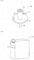
Fig. 2] Fig. 2 is a perspective view illustrating a suction nozzle. - [
Fig. 3] Fig. 3 is a perspective view illustrating a nozzle management device. - [
Fig. 4] Fig. 4 is a schematic diagram illustrating an imaging device of the present invention. - [
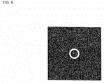
Fig. 5] Fig. 5 is a diagram illustrating an image of a perspective from under the suction nozzle in an ordinary state. - [
Fig. 6] Fig. 6 is a diagram illustrating an image of a perspective from under the suction nozzle in a state in which foreign matter adheres to an outer edge side of a lower end face. - [
Fig. 7] Fig. 7 is a diagram illustrating an image of a perspective from under the suction nozzle in a state in which foreign matter adheres to a lower end face. - [
Fig. 8] Fig. 8 is a diagram illustrating an image of a perspective from under the suction nozzle in a state in which the lower end face is missing. - [
Fig. 9] Fig. 9 is a diagram illustrating an image of a perspective from a side of the suction nozzle. - Hereinafter, a detailed description will be given of the example of the present invention with reference to the drawings as an embodiment of the present invention.
-
Fig. 1 illustrates an electronic component mounting device (hereinafter there is a case in which this is shortened to "mounting device") 10. Themounting device 10 includes asingle system base 12 and two electronic component mounting machines (hereinafter, there is a case in which this is shortened to "mounting machines") 14 which are provided adjacently on thesystem base 12. The direction in which themounting machines 14 are lined up will be referred to as an X-axis direction and a horizontal direction which is perpendicular to the direction will be referred to as a Y-axis direction. - Each of the
mounting machines 14 is mainly provided with a mounting machinemain body 20, aconveyance device 22, a mounting head moving device (hereinafter, there is a case in which this is shortened to a "moving device") 24, amounting head 26, asupply device 28, and anozzle station 30. The mounting machinemain body 20 is configured using aframe section 32 and abeam section 34 which bridges over theframe section 32. - The
conveyance device 22 is provided with twoconveyor devices conveyor devices frame section 32 to be parallel to each other and to extend in the X-axis direction. The twoconveyor devices conveyor devices - The
moving device 24 is an XY robot-type moving device. Themoving device 24 is provided with an electromagnetic motor (not illustrated) which causes aslider 50 to slide in the X-axis direction and an electromagnetic motor (not illustrated) which causes theslider 50 to slide in the Y-axis direction. Themounting head 26 is attached to theslider 50, and themounting head 26 is caused to move to an arbitrary position above theframe section 32 by the operation of the two electromagnetic motors. - The
mounting head 26 mounts the electronic component onto the circuit board. Asuction nozzle 60 is provided on the lower end face of themounting head 26. As illustrated inFig. 2 , thesuction nozzle 60 is configured using abody cylinder 64, aflange section 66, asuction pipe 68, and alocking pin 70. Thebody cylinder 64 is cylindrical, and theflange section 66 is fixed to protrude from the outer circumferential surface of thebody cylinder 64. Thesuction pipe 68 is a narrow pipe shape and is held by thebody cylinder 64 to be capable of moving in an axial line direction in a state of extending downward from the lower end portion of thebody cylinder 64. Thelocking pin 70 is provided on the upper end portion of thebody cylinder 64 so as to extend in the radial direction of thebody cylinder 64. Thesuction nozzle 60 is attached to themounting head 26 to be capable of being attached and detached in a single operation using thelocking pin 70. A spring (not illustrated) is embedded in themounting head 26, and the spring applies an elastic force to thesuction pipe 68 of thesuction nozzle 60 which is attached to themounting head 26. Accordingly, thesuction pipe 68 is biased in a direction extending downward from the lower end portion of thebody cylinder 64 by the elastic force of the spring which is embedded in themounting head 26. - The
suction nozzle 60 communicates with a positive and negative pressure supply device (not illustrated) via negative pressure air and positive pressure air passage. Each of thesuction nozzles 60 sucks and holds an electronic component using a negative pressure and releases the held electronic component using a positive pressure. Themounting head 26 includes a nozzle lifting and lowering device (not illustrated) which lifts and lowers thesuction nozzle 60. Themounting head 26 changes the position of the held electronic component in the up-down direction using the nozzle lifting and lowering device. - The
supply device 28 is a feeder-type supply device and, as illustrated inFig. 1 , is installed on the end portion of the front side of theframe section 32. Thesupply device 28 includes atape feeder 72. Thetape feeder 72 accommodates taped components in a wound state. The taped components are obtained by taping the electronic components. Thetape feeder 72 feeds out the taped components using a feed device (not illustrated). Accordingly, the feeder-type supply device 28 supplies the electronic components to the supply position by feeding out the taped components. - The
nozzle station 30 includes anozzle tray 77 which accommodates themultiple suction nozzles 60. In thenozzle station 30, the exchanging of thesuction nozzle 60 which is attached to the mountinghead 26 with thesuction nozzle 60 which is accommodated in thenozzle tray 77, and the like are performed as necessary. Thenozzle tray 77 is capable of being attached and detached in relation to thenozzle station 30, and is capable of performing, on the outside of the mountingmachines 14, the collection of thesuction nozzles 60 which are accommodated in thenozzle tray 77, the refilling of thenozzle tray 77 with thesuction nozzles 60, and the like. - According to the configuration which is described above, in the mounting
machine 14, it is possible to perform the mounting work on the circuit board which is held by theconveyance device 22 using the mountinghead 26. Specifically, according to the instructions of the control device (not illustrated) of the mountingmachine 14, the circuit board is conveyed to a working position, and at this position, is held in a fixed manner by the board holding device. Thetape feeder 72 feeds out the taped components and supplies the electronic components to the supply position according to the instructions of the control device. The mountinghead 26 moves above the supply position of the electronic components and sucks and holds the electronic component using thesuction nozzle 60. Subsequently, the mountinghead 26 moves above the circuit board, and the electronic component which is being held is mounted onto the circuit board. - As described above, in the mounting
machine 14, the electronic component which is supplied by thetape feeder 72 is sucked and held by thesuction nozzle 60, and the electronic component is mounted onto the circuit board. Therefore, when a problem arises in thesuction nozzle 60, it is not possible to perform appropriate mounting work. In consideration of this, thenozzle tray 77 is removed from thenozzle station 30 of the mountingmachine 14, and the inspection of thesuction nozzles 60 which are accommodated in thenozzle tray 77 is performed in the nozzle management device. - Specifically, as illustrated in
Fig. 3 , anozzle management device 78 is a substantially rectangular parallelepiped shape, and adrawer 79 for storing thenozzle tray 77 inside thenozzle management device 78 or for removing thenozzle tray 77 from thenozzle management device 78 is provided on the front face. The suction nozzles 60 which are stored in thenozzle management device 78 are subjected to management and inspection in thenozzle management device 78. When inspecting thesuction nozzle 60, the imaging of thesuction nozzle 60 is performed, and inspection of the state of thesuction pipe 68 of thesuction nozzle 60 and the protrusion amount of thesuction pipe 68 from thebody cylinder 64 is performed based on the captured image data. As illustrated inFig. 4 , animaging device 80 which performs the imaging of thesuction nozzle 60 is provided with three reflectingmirrors lateral lighting device 90, two light shielding blocks 92 and 94, and acamera 96. - In the
nozzle management device 78, the inspectiontarget suction nozzle 60 is gripped by anozzle gripping tool 100. Thesuction nozzle 60 which is gripped by thenozzle gripping tool 100 is imaged by theimaging device 80. Of the three reflectingmirrors mirror 82 is installed under thesuction nozzle 60 which is gripped by thenozzle gripping tool 100 in a state of being inclined by approximately 45°. The reflectance of the first reflectingmirror 82 is 50%, and the transmittance is 50%. - Of the three reflecting
mirrors mirror 84 is installed to the side of the first reflectingmirror 82 in a state of being inclined by approximately 45° in the same direction as the first reflectingmirror 82. The reflectance of the second reflectingmirror 84 is 30%, and the transmittance is 70%. Of the three reflectingmirrors mirror 86 is installed above the second reflectingmirror 84 in a state of being inclined by approximately 45° in the same direction as the second reflectingmirror 84. The reflectance of the third reflectingmirror 86 is 100%, and the transmittance is 0%. - The downward lighting device 88 is provided with
lateral lighting 102 andvertical lighting 104. Thelateral lighting 102 is approximately annular and is installed between the first reflectingmirror 82 and thesuction nozzle 60 which is gripped by thenozzle gripping tool 100 in a state of facing upward. An axial line of thesuction nozzle 60 which is gripped by thenozzle gripping tool 100 substantially matches the center of the annularlateral lighting 102 in the up-down direction. Thevertical lighting 104 is installed under the first reflectingmirror 82 in a state of facing upward. Accordingly, thelateral lighting 102 irradiates thesuction nozzle 60 which is gripped by thenozzle gripping tool 100 with light from diagonally below, and thevertical lighting 104 irradiates thesuction nozzle 60 which is gripped by thenozzle gripping tool 100 with light from directly below via the first reflectingmirror 82 and an inner diameter portion of thelateral lighting 102. - The light which is radiated from both of the
lateral lighting 102 and thevertical lighting 104 is reflected by the lower end face of thesuction pipe 68 of thesuction nozzle 60 which is gripped by thenozzle gripping tool 100, travels along an optical path (a path between two dotted lines 106), and is incident on the first reflectingmirror 82. Of the light which is incident on the first reflectingmirror mirror 82, travels along an optical path (a path between two dotted lines 108), and is incident on the second reflectingmirror 84. This is because the reflectance of the first reflectingmirror 82 is 50% . Thecamera 96 is installed on a line extending from the light which is incident on the second reflectingmirror 84. Therefore, of the light which is incident on the second reflectingmirror mirror 84, travels along an optical path (a path between two dotted lines 110), and is incident on thecamera 96. - The
camera 96 includes alens 112 and animage sensor element 114, and the light which is incident on thecamera 96 is detected by theimage sensor element 114 via thelens 112. Incidentally, the light which is detected by theimage sensor element 114 is light equivalent to 35% light amount (0.5 x 0.7 = 0.35) of the light which is reflected by the lower end face of thesuction pipe 68 of thesuction nozzle 60 which is gripped by thenozzle gripping tool 100. Accordingly, as illustrated inFig. 5 , an image of the lower end face of thesuction pipe 68 of thesuction nozzle 60 is obtained. Since the light which is detected by theimage sensor element 114 is the light which is reflected by the lower end face of thesuction pipe 68, the lower end face of thesuction pipe 68 is indicated as white in the image. In this manner, by imaging the lower end face of thesuction pipe 68 using thecamera 96, it is possible to inspect the state of thesuction pipe 68 of thesuction nozzle 60. - Specifically, for example, in a case in which foreign matter such as solder adheres to the outer edge side of the tip portion of the
suction pipe 68 when the lower end face of thesuction pipe 68 is imaged by thecamera 96, the image illustrated inFig. 6 is obtained. In this image, a protruding portion is illustrated on the outer edge side of the lower end face of thesuction pipe 68, and due to this protruding portion, it is determined that foreign matter adheres to a tip portion of thesuction pipe 68. Even in a case in which foreign matter adhered to the inner edge side of the tip portion of thesuction pipe 68, naturally, since the protruding portion is illustrated on the inner edge side of the lower end face of thesuction pipe 68 in the image which is imaged by thecamera 96, it is determined that foreign matter adheres to the tip portion of thesuction pipe 68. - In this manner, in a case in which the imaging of the lower end face of the
suction pipe 68 is performed according to the procedure described above, that is, in a case in which imaging (hereinafter, there is a case in which this is denoted as "full irradiation imaging") based on the light which is reflected by the lower end face of thesuction pipe 68 of thesuction nozzle 60 is performed when thesuction nozzle 60 is irradiated with the lighting of both thelateral lighting 102 and thevertical lighting 104, it is possible to appropriately determine thesuction nozzle 60 in which foreign matter adheres to the outer edge side or the inner edge side of the tip portion of thesuction pipe 68. However, in a case in which the foreign matter adheres to the lower end face of thesuction pipe 68, there is a concern that it is not possible to appropriately determine the presence or the absence of the foreign matter using the image obtained when the full irradiation imaging is performed. In a case in which the lower end face of thesuction pipe 68 is missing, there is a concern that it is not possible to appropriately determine whether or not the lower end face of thesuction pipe 68 is missing using the image obtained when the full irradiation imaging is performed. In other words, in a case in which an abnormality arises in the lower end face of thesuction pipe 68 , there is a concern that it is not possible to appropriately determine the abnormality of the lower end face of thesuction pipe 68 using the image obtained when the full irradiation imaging is performed. - Specifically, for example, the image obtained when the full irradiation imaging is performed on the
suction nozzle 60 in which foreign matter adheres to the lower end face of thesuction pipe 68 or is performed on thesuction nozzle 60 in which a portion of the lower end face of thesuction pipe 68 is missing is the image illustrated inFig. 5 . In other words, in a case in which foreign matter adheres to the lower end face of thesuction pipe 68 or in a case in which a portion of the lower end face of thesuction pipe 68 is missing, it is not possible to detect the adhesion of foreign matter or the tip portion of thesuction pipe 68 being missing in the image obtained when the full irradiation imaging is performed. - Meanwhile, in a case in which imaging based on the light which is reflected by the lower end face of the
suction pipe 68 of thesuction nozzle 60 when thesuction nozzle 60 is irradiated with only thevertical lighting 104 is performed without being irradiated with the lateral lighting 102 (hereinafter, there is a case in which this is denoted as "vertical irradiation imaging"), the state of the lower end face of thesuction pipe 68 is appropriately imaged. Specifically, for example, in a case in which foreign matter adheres to the lower end face of thesuction pipe 68, thesuction nozzle 60 is irradiated with only thevertical lighting 104, and when the lower end face of thesuction pipe 68 is imaged by thecamera 96, the image illustrated inFig. 7 is obtained. In this image, a black portion is present on the lower end face of thesuction pipe 68, and due to this portion, it is determined that foreign matter adheres to the lower end face of thesuction pipe 68. Specifically, for example, in a case in which a portion of the lower end face of thesuction pipe 68 is missing, thesuction nozzle 60 is irradiated with only thevertical lighting 104, and when the lower end face of thesuction pipe 68 is imaged by thecamera 96, the image illustrated inFig. 8 is obtained. In this image, a portion of the lower end face of thesuction pipe 68 is absent, and due to this absence, it is determined that a portion of the lower end face of thesuction pipe 68 is missing. - However, during the vertical irradiation imaging, there is a concern that it is not possible to appropriately image foreign matter which adheres to the outer edge side or the inner edge side of the tip portion of the
suction pipe 68. In other words, the image obtained when the vertical irradiation imaging is performed on thesuction nozzle 60 in which foreign matter adheres to the outer edge side or the inner edge side of the tip portion of thesuction pipe 68 is the image illustrated inFig. 5 . In other words, in a case in which foreign matter adheres to the outer edge side or the inner edge side of the tip portion of thesuction pipe 68, it is not possible to detect the adhesion of foreign matter in the image obtained when the vertical irradiation imaging is performed. - In light of this fact, in the
imaging device 80, the full irradiation imaging and the vertical irradiation imaging are performed and the state of the tip portion of thesuction pipe 68 is inspected based on the image obtained when the full irradiation imaging is performed and the image obtained when the vertical irradiation imaging is performed. Therefore, in a case in which foreign matter adheres to the outer edge side or the inner edge side of the tip portion of thesuction pipe 68, the adhesion of foreign matter is detected using the image obtained when the full irradiation imaging is performed. In a case in which foreign matter adheres to the lower end face of thesuction pipe 68 or in a case in which the tip portion of thesuction pipe 68 is missing, the adhesion of foreign matter or the tip portion of thesuction pipe 68 being missing is detected using the image obtained when the vertical irradiation imaging is performed. Accordingly, it is possible to appropriately inspect the state of the tip portion of thesuction pipe 68. - The shutter speed when the full irradiation imaging is performed is reduced to be slower than the shutter speed when the vertical irradiation imaging is performed. In other words, the light exposure time when the full irradiation imaging is performed is longer than the light exposure time when the vertical irradiation imaging is performed. Therefore, when the full irradiation imaging is performed, the
image sensor element 114 is capable of detecting much of the light which is radiated from both of thelateral lighting 102 and thevertical lighting 104, and the contour of the image of the lower end face of thesuction pipe 68 becomes clear in the image obtained when the full irradiation imaging is performed. Accordingly, it is possible to more appropriately detect foreign matter which adheres to the outer edge side or the inner edge side of the tip portion of thesuction pipe 68. Meanwhile, during the vertical irradiation imaging, the detection amount of the light by theimage sensor element 114 is reduced; however, in accordance with the reduction in the detection amount of the light, unevenness on the lower end face of thesuction pipe 68 becomes clear in the image obtained when the vertical irradiation imaging is performed. Accordingly, it is possible to more appropriately detect foreign matter which adheres to the lower end face of thesuction pipe 68 or to detect that the tip portion of thesuction pipe 68 is missing. - In the
nozzle management device 78, in addition to the inspection of thesuction nozzle 60, cleaning of thesuction nozzle 60 is also performed, and after the cleaning, thesuction nozzle 60 is dried and stored in thenozzle management device 78. Therefore, there is a case in which whether or not water droplets remain on thesuction nozzle 60 which is to be stored is inspected by theimaging device 80. There are many cases in which the water droplets which remain on thesuction nozzle 60 remain on the lower end face of thesuction pipe 68 or on the outer edge side or the inner edge side of the tip portion of thesuction pipe 68. Therefore, according to theimaging device 80, it is possible to appropriately detect the water droplets which remain on thesuction nozzle 60. - When the tip portion of the
suction pipe 68 of thesuction nozzle 60 is imaged from the side, the tip portion of thesuction pipe 68 is irradiated from the side by thelateral lighting device 90. Specifically, thelateral lighting device 90 is a backlight system lighting device, and as illustrated inFig. 4 , irradiates thesuction nozzle 60 which is gripped by thenozzle gripping tool 100 with light from the side and is installed such that the light with which thesuction nozzle 60 is irradiated is incident on the third reflectingmirror 86. Of the two light shielding blocks 92 and 94, the firstlight shielding block 92 is installed between thelateral lighting device 90 and thesuction nozzle 60 which is gripped by thenozzle gripping tool 100, and of the two light shielding blocks 92 and 94, the secondlight shielding block 94 is installed between the third reflectingmirror 86 and thesuction nozzle 60 which is gripped by thenozzle gripping tool 100. -
Slits light shielding block 92 and the secondlight shielding block 94, respectively, and the twoslits lateral lighting device 90. Therefore, thelateral lighting device 90 irradiates thesuction nozzle 60 which is gripped by thenozzle gripping tool 100 with light from the space of theslit 120 of the firstlight shielding block 92, and the irradiated light is incident on the third reflectingmirror 86 from the space of theslit 122 of the secondlight shielding block 94. At this time, the light which is radiated from thelateral lighting device 90 travels along an optical path (a path between two dotted lines 124) and is incident on the third reflectingmirror 86. - Of the light which is incident on the third reflecting
mirror mirror 86, travels along an optical path (a path between two dotted lines 126), and is incident on the second reflectingmirror 84. This is because the reflectance of the third reflectingmirror 86 is 100%. Next, of the light which is incident on the second reflectingmirror mirror 84, travels along an optical path (a path between two dotted lines 128), and is incident on thecamera 96. The light which is detected by theimage sensor element 114 is light equivalent to 30% light amount (1.0 x 0.3 = 0.3) of the light which is radiated from thelateral lighting device 90. Accordingly, as illustrated inFig. 9 , an image of from the side of thesuction pipe 68 of thesuction nozzle 60 is obtained. Since the light which is detected by theimage sensor element 114 is the light which passes through the space of theslit 122, the inner portion of theslit 122 is indicated as white in the image. Since a portion of the light which passes through theslit 122 is blocked by thesuction pipe 68, the image of thesuction pipe 68 is indicated as black. - According to the procedure described above, the inspection of the protrusion amount of the
suction pipe 68 from thebody cylinder 64 is performed by thesuction pipe 68 of thesuction nozzle 60 being imaged from the side. Specifically, the position of the tip portion of thesuction pipe 68 is detected based on the image. The protrusion amount of thesuction pipe 68 from thebody cylinder 64 is calculated and whether or not the protrusion amount of thesuction pipe 68 is an appropriate amount is determined based on the position of the tip portion of thesuction pipe 68. - In this manner, in the
imaging device 80, it is possible to perform the imaging of the lower end face and the imaging of the side of thesuction nozzle 60 using thesingle camera 96. Accordingly, it is no longer necessary to use two cameras, a camera for the imaging of the lower end face of thesuction nozzle 60 and a camera for the imaging of the side face, and it is possible to obtain a reduction in the cost of the imaging device. - Incidentally, in the example, the
suction nozzle 60 is an example of an inspection target object. Theimaging device 80 is an example of an inspection device. Thecamera 96 is an example of an imaging device. Thelateral lighting 102 is an example of lateral lighting and second lighting. Thevertical lighting 104 is an example of vertical irradiation and first lighting. The vertical irradiation lighting is an example of first irradiation lighting. - Note that, the present invention is not limited to the example described above, and it is possible to carry out the present invention in various modes subjected to various modifications and improvements based on the knowledge of a person skilled in the art. Specifically, for example, in the example described above, the full irradiation imaging and the vertical irradiation imaging are performed; however, in addition to the combination of the full irradiation imaging and the vertical irradiation imaging, it is possible to perform the imaging of a combination of the imaging of at least two of imaging which is based on light which is reflected by the lower end face of the
suction pipe 68 of thesuction nozzle 60 when thesuction nozzle 60 is irradiated by only thelateral lighting 102 without the irradiation of the vertical lighting 104 (hereinafter, there are cases in which this is denoted as "lateral irradiation imaging"), full irradiation imaging, and vertical irradiation imaging. In other words, it is possible to perform each of the imaging of three of the full irradiation imaging, the vertical irradiation imaging, and the lateral lighting imaging, the imaging of two of the full irradiation imaging and the lateral lighting imaging, and the imaging of two of the vertical irradiation imaging and the lateral lighting imaging. Accordingly, it is possible to perform the inspection of thesuction nozzle 60 according to the merits and the demerits of each kind of imaging and to appropriately perform the inspection of thesuction nozzle 60. The lateral irradiation lighting is an example of second irradiation lighting. - In the example which is described above, the shutter speed during the full irradiation imaging is slower than the shutter speed during the vertical irradiation imaging; however, the shutter speed during the full irradiation imaging may be faster than the shutter speed during the vertical irradiation imaging, and the shutter speed during the full irradiation imaging may be the same as the shutter speed during the vertical irradiation imaging.
- In the example which is described above, the inspection device of the present invention is adopted as a device for performing the inspection of the
suction nozzle 60; however, it is possible to adopt the inspection device of the present invention as a device which performs the inspection of various members other than thesuction nozzle 60. -
- 60: suction nozzle (inspection target object), 80: imaging device (inspection device), 96: camera (imaging device), 102: lateral lighting, 104: vertical lighting.
Claims (6)
- An inspection device for inspecting an inspection target object based on light with which the inspection target object is irradiated, the device comprising:vertical lighting which irradiates the inspection target object with light;lateral lighting which irradiates the inspection target object with light; andan imaging device which images the inspection target object based on light which is reflected by the inspection target object when the inspection target object is irradiated from at least one of the vertical lighting and the lateral lighting,wherein the imaging device performs at least two of full irradiation imaging which is imaging of the inspection target object based on light which is reflected by the inspection target object when the inspection target object is irradiated from both the vertical lighting and the lateral lighting, vertical irradiation imaging which is imaging of the inspection target object based on light which is reflected by the inspection target object when the inspection target object is irradiated from the vertical lighting without being irradiated from the lateral lighting, and lateral irradiation imaging which is imaging of the inspection target object based on light which is reflected by the inspection target object when the inspection target object is irradiated from the lateral lighting without being irradiated from the vertical lighting.
- The inspection device according to Claim 1,
wherein the imaging device performs all of the full irradiation imaging, the vertical irradiation imaging, and the lateral irradiation imaging. - The inspection device according to Claim 1 or 2,
wherein when the imaging device performs one imaging from among the full irradiation imaging, the vertical irradiation imaging, and the lateral irradiation imaging, and a different imaging from the one imaging from among the full irradiation imaging, the vertical irradiation imaging, and the lateral irradiation imaging, a shutter speed during the first imaging and a shutter speed during the different imaging are changed. - An inspection method for inspecting an inspection target object using an inspection device including vertical lighting which irradiates the inspection target object with light, lateral lighting which irradiates the inspection target object with light, and an imaging device which images the inspection target object based on light which is reflected by the inspection target object when the inspection target object is irradiated from at least one of the vertical lighting and the lateral lighting, the method comprising:an imaging step of causing the imaging device to perform at least two of full irradiation imaging which is imaging of the inspection target object based on light which is reflected by the inspection target object when the inspection target object is irradiated from both the vertical lighting and the lateral lighting, vertical irradiation imaging which is imaging of the inspection target object based on light which is reflected by the inspection target object when the inspection target object is irradiated from the vertical lighting without being irradiated from the lateral lighting, and lateral irradiation imaging which is imaging of the inspection target object based on light which is reflected by the inspection target object when the inspection target object is irradiated from the lateral lighting without being irradiated from the vertical lighting; andan inspection step of inspecting the inspection target object based on images which are obtained using the at least two imaging processes which are performed in the imaging step.
- An inspection device for inspecting an inspection target object based on light with which the inspection target object is irradiated, the inspection device comprising:first lighting which irradiates the inspection target object with light;second lighting which irradiates the inspection target object with light; andan imaging device which images the inspection target object based on light which is reflected by the inspection target object when the inspection target object is irradiated from at least one of the first lighting and the second lighting,wherein the imaging device performs at least two of full irradiation imaging which is imaging of the inspection target object based on light which is reflected by the inspection target object when the inspection target object is irradiated from both the first lighting and the second lighting, first irradiation imaging which is imaging of the inspection target object based on light which is reflected by the inspection target object when the inspection target object is irradiated from the first lighting without being irradiated from the second lighting, and second irradiation imaging which is imaging of the inspection target object based on light which is reflected by the inspection target object when the inspection target object is irradiated from the second lighting without being irradiated from the first lighting.
- The inspection device according to Claim 5,
wherein the inspection target object includes an end surface which faces at least one of the first lighting and the second lighting, and
wherein the end surface of the inspection target object is inspected based on an image which is obtained using one imaging from among the full lighting imaging, the first imaging, and the second imaging, and a portion other than the end surface of the inspection target object is inspected based on an image which is obtained using one different imaging from the one imaging from among the full lighting imaging, the first imaging, and the second imaging.
Applications Claiming Priority (1)
| Application Number | Priority Date | Filing Date | Title |
|---|---|---|---|
| PCT/JP2015/055527 WO2016135910A1 (en) | 2015-02-26 | 2015-02-26 | Inspection device and inspection method |
Publications (3)
| Publication Number | Publication Date |
|---|---|
| EP3264071A1 true EP3264071A1 (en) | 2018-01-03 |
| EP3264071A4 EP3264071A4 (en) | 2018-08-01 |
| EP3264071B1 EP3264071B1 (en) | 2026-04-15 |
Family
ID=56788588
Family Applications (1)
| Application Number | Title | Priority Date | Filing Date |
|---|---|---|---|
| EP15883204.8A Active EP3264071B1 (en) | 2015-02-26 | 2015-02-26 | Inspection device and inspection method |
Country Status (3)
| Country | Link |
|---|---|
| EP (1) | EP3264071B1 (en) |
| JP (1) | JP6785214B2 (en) |
| WO (1) | WO2016135910A1 (en) |
Cited By (1)
| Publication number | Priority date | Publication date | Assignee | Title |
|---|---|---|---|---|
| US11924977B2 (en) | 2019-07-25 | 2024-03-05 | Fuji Corporation | Device and method for inspecting adsorption nozzle |
Family Cites Families (12)
| Publication number | Priority date | Publication date | Assignee | Title |
|---|---|---|---|---|
| JP3022753B2 (en) * | 1995-10-05 | 2000-03-21 | 石塚硝子株式会社 | Defect inspection device for container top |
| JP4260545B2 (en) * | 2003-05-20 | 2009-04-30 | ヤマハ発動機株式会社 | Surface mount machine |
| JP2008082900A (en) * | 2006-09-27 | 2008-04-10 | Sumitomo Electric Ind Ltd | Appearance inspection device |
| JP5549155B2 (en) * | 2009-09-04 | 2014-07-16 | セイコーエプソン株式会社 | Surface inspection method |
| JP5443938B2 (en) * | 2009-10-19 | 2014-03-19 | Juki株式会社 | Electronic component mounting equipment |
| JP5660810B2 (en) * | 2010-06-16 | 2015-01-28 | 富士機械製造株式会社 | Adsorption nozzle inspection device for component mounting machines |
| JP5946998B2 (en) * | 2011-05-24 | 2016-07-06 | 富士機械製造株式会社 | Image processing apparatus and electronic component mounting machine |
| JP5913866B2 (en) * | 2011-08-25 | 2016-04-27 | 富士機械製造株式会社 | Master data creation method for board inspection |
| JP5798047B2 (en) * | 2012-01-10 | 2015-10-21 | ヤマハ発動機株式会社 | Component imaging device, surface mounter and component inspection device |
| JP6055241B2 (en) * | 2012-08-29 | 2016-12-27 | 富士機械製造株式会社 | Imaging condition optimization method and imaging condition optimization system |
| JP5887499B2 (en) * | 2013-03-19 | 2016-03-16 | パナソニックIpマネジメント株式会社 | Nozzle inspection device and component mounting system |
| JP5949690B2 (en) * | 2013-07-25 | 2016-07-13 | Jfeスチール株式会社 | Evaluation method and evaluation apparatus |
-
2015
- 2015-02-26 EP EP15883204.8A patent/EP3264071B1/en active Active
- 2015-02-26 JP JP2017501760A patent/JP6785214B2/en active Active
- 2015-02-26 WO PCT/JP2015/055527 patent/WO2016135910A1/en not_active Ceased
Cited By (1)
| Publication number | Priority date | Publication date | Assignee | Title |
|---|---|---|---|---|
| US11924977B2 (en) | 2019-07-25 | 2024-03-05 | Fuji Corporation | Device and method for inspecting adsorption nozzle |
Also Published As
| Publication number | Publication date |
|---|---|
| EP3264071B1 (en) | 2026-04-15 |
| EP3264071A4 (en) | 2018-08-01 |
| JPWO2016135910A1 (en) | 2017-11-30 |
| JP6785214B2 (en) | 2020-11-18 |
| WO2016135910A1 (en) | 2016-09-01 |
Similar Documents
| Publication | Publication Date | Title |
|---|---|---|
| CN107006147B (en) | Component mounter | |
| CN1818542B (en) | Inspection method and device for installed electronic components | |
| JP6460600B2 (en) | Detection device | |
| CN106538089B (en) | Nozzle Storage | |
| EP3032933A1 (en) | Electronic component mounting machine and transfer confirmation method | |
| CN107926154A (en) | Element fixing apparatus | |
| CN108142000A (en) | Operation system of substrate and element fixing apparatus | |
| KR102057918B1 (en) | Component mounting device | |
| EP3174377B1 (en) | Inspection method | |
| JP6727768B2 (en) | Board working equipment | |
| KR20190057120A (en) | Surface machining, part recognition, parts recognition | |
| EP2897449A1 (en) | Work system for substrate, work-sequence-optimizing program, and workbench-quantity-determining program | |
| EP3264071B1 (en) | Inspection device and inspection method | |
| JP6475165B2 (en) | Mounting device | |
| JP6830329B2 (en) | Inspection equipment and inspection method | |
| CN114175872B (en) | Nozzle inspection device and nozzle inspection method | |
| CN114041332B (en) | Mounting device, mounting system, and inspection mounting method | |
| JP5977579B2 (en) | Board work equipment | |
| JP6830316B2 (en) | Detection device | |
| CN108029235A (en) | Control device | |
| KR101332005B1 (en) | Apparatus and method of mounting component | |
| WO2023162140A1 (en) | Inspection device and inspection method | |
| JP2023060597A (en) | Component mounting system | |
| WO2018096574A1 (en) | Mounting machine | |
| KR20120132429A (en) | Electronic component mounting apparatus |
Legal Events
| Date | Code | Title | Description |
|---|---|---|---|
| STAA | Information on the status of an ep patent application or granted ep patent |
Free format text: STATUS: THE INTERNATIONAL PUBLICATION HAS BEEN MADE |
|
| PUAI | Public reference made under article 153(3) epc to a published international application that has entered the european phase |
Free format text: ORIGINAL CODE: 0009012 |
|
| STAA | Information on the status of an ep patent application or granted ep patent |
Free format text: STATUS: REQUEST FOR EXAMINATION WAS MADE |
|
| 17P | Request for examination filed |
Effective date: 20170803 |
|
| AK | Designated contracting states |
Kind code of ref document: A1 Designated state(s): AL AT BE BG CH CY CZ DE DK EE ES FI FR GB GR HR HU IE IS IT LI LT LU LV MC MK MT NL NO PL PT RO RS SE SI SK SM TR |
|
| AX | Request for extension of the european patent |
Extension state: BA ME |
|
| DAX | Request for extension of the european patent (deleted) | ||
| A4 | Supplementary search report drawn up and despatched |
Effective date: 20180702 |
|
| RIC1 | Information provided on ipc code assigned before grant |
Ipc: G01N 21/88 20060101AFI20180625BHEP Ipc: H05K 13/02 20060101ALI20180625BHEP |
|
| RAP1 | Party data changed (applicant data changed or rights of an application transferred) |
Owner name: FUJI CORPORATION |
|
| RIN1 | Information on inventor provided before grant (corrected) |
Inventor name: SHIMOSAKA, KENJI Inventor name: HOSHIKAWA, KAZUMI Inventor name: IBE, TADAKATSU Inventor name: SUZUKI, DAISUKE |
|
| STAA | Information on the status of an ep patent application or granted ep patent |
Free format text: STATUS: EXAMINATION IS IN PROGRESS |
|
| 17Q | First examination report despatched |
Effective date: 20210607 |
|
| P01 | Opt-out of the competence of the unified patent court (upc) registered |
Effective date: 20230328 |
|
| GRAP | Despatch of communication of intention to grant a patent |
Free format text: ORIGINAL CODE: EPIDOSNIGR1 |
|
| STAA | Information on the status of an ep patent application or granted ep patent |
Free format text: STATUS: GRANT OF PATENT IS INTENDED |
|
| RIC1 | Information provided on ipc code assigned before grant |
Ipc: G01N 21/88 20060101AFI20251103BHEP Ipc: G01N 21/94 20060101ALI20251103BHEP Ipc: G01N 21/95 20060101ALI20251103BHEP Ipc: H05K 13/08 20060101ALI20251103BHEP Ipc: G01N 21/952 20060101ALN20251103BHEP |
|
| INTG | Intention to grant announced |
Effective date: 20251112 |
|
| GRAS | Grant fee paid |
Free format text: ORIGINAL CODE: EPIDOSNIGR3 |
|
| GRAA | (expected) grant |
Free format text: ORIGINAL CODE: 0009210 |
|
| STAA | Information on the status of an ep patent application or granted ep patent |
Free format text: STATUS: THE PATENT HAS BEEN GRANTED |
|
| AK | Designated contracting states |
Kind code of ref document: B1 Designated state(s): AL AT BE BG CH CY CZ DE DK EE ES FI FR GB GR HR HU IE IS IT LI LT LU LV MC MK MT NL NO PL PT RO RS SE SI SK SM TR |
|
| REG | Reference to a national code |
Ref country code: CH Ref legal event code: F10 Free format text: ST27 STATUS EVENT CODE: U-0-0-F10-F00 (AS PROVIDED BY THE NATIONAL OFFICE) Effective date: 20260415 Ref country code: GB Ref legal event code: FG4D |
|
| REG | Reference to a national code |
Ref country code: DE Ref legal event code: R096 Ref document number: 602015093257 Country of ref document: DE |