EP3263959A1 - Sanitärarmatur - Google Patents
Sanitärarmatur Download PDFInfo
- Publication number
- EP3263959A1 EP3263959A1 EP17001084.7A EP17001084A EP3263959A1 EP 3263959 A1 EP3263959 A1 EP 3263959A1 EP 17001084 A EP17001084 A EP 17001084A EP 3263959 A1 EP3263959 A1 EP 3263959A1
- Authority
- EP
- European Patent Office
- Prior art keywords
- mixing shaft
- ring
- mixing
- inner peripheral
- peripheral wall
- Prior art date
- Legal status (The legal status is an assumption and is not a legal conclusion. Google has not performed a legal analysis and makes no representation as to the accuracy of the status listed.)
- Granted
Links
Images


Classifications
-
- F—MECHANICAL ENGINEERING; LIGHTING; HEATING; WEAPONS; BLASTING
- F16—ENGINEERING ELEMENTS AND UNITS; GENERAL MEASURES FOR PRODUCING AND MAINTAINING EFFECTIVE FUNCTIONING OF MACHINES OR INSTALLATIONS; THERMAL INSULATION IN GENERAL
- F16K—VALVES; TAPS; COCKS; ACTUATING-FLOATS; DEVICES FOR VENTING OR AERATING
- F16K11/00—Multiple-way valves, e.g. mixing valves; Pipe fittings incorporating such valves
- F16K11/02—Multiple-way valves, e.g. mixing valves; Pipe fittings incorporating such valves with all movable sealing faces moving as one unit
- F16K11/08—Multiple-way valves, e.g. mixing valves; Pipe fittings incorporating such valves with all movable sealing faces moving as one unit comprising only taps or cocks
- F16K11/085—Multiple-way valves, e.g. mixing valves; Pipe fittings incorporating such valves with all movable sealing faces moving as one unit comprising only taps or cocks with cylindrical plug
- F16K11/0856—Multiple-way valves, e.g. mixing valves; Pipe fittings incorporating such valves with all movable sealing faces moving as one unit comprising only taps or cocks with cylindrical plug having all the connecting conduits situated in more than one plane perpendicular to the axis of the plug
-
- F—MECHANICAL ENGINEERING; LIGHTING; HEATING; WEAPONS; BLASTING
- F16—ENGINEERING ELEMENTS AND UNITS; GENERAL MEASURES FOR PRODUCING AND MAINTAINING EFFECTIVE FUNCTIONING OF MACHINES OR INSTALLATIONS; THERMAL INSULATION IN GENERAL
- F16K—VALVES; TAPS; COCKS; ACTUATING-FLOATS; DEVICES FOR VENTING OR AERATING
- F16K11/00—Multiple-way valves, e.g. mixing valves; Pipe fittings incorporating such valves
- F16K11/02—Multiple-way valves, e.g. mixing valves; Pipe fittings incorporating such valves with all movable sealing faces moving as one unit
- F16K11/06—Multiple-way valves, e.g. mixing valves; Pipe fittings incorporating such valves with all movable sealing faces moving as one unit comprising only sliding valves, i.e. sliding closure elements
- F16K11/072—Multiple-way valves, e.g. mixing valves; Pipe fittings incorporating such valves with all movable sealing faces moving as one unit comprising only sliding valves, i.e. sliding closure elements with pivoted closure members
- F16K11/076—Multiple-way valves, e.g. mixing valves; Pipe fittings incorporating such valves with all movable sealing faces moving as one unit comprising only sliding valves, i.e. sliding closure elements with pivoted closure members with sealing faces shaped as surfaces of solids of revolution
-
- F—MECHANICAL ENGINEERING; LIGHTING; HEATING; WEAPONS; BLASTING
- F16—ENGINEERING ELEMENTS AND UNITS; GENERAL MEASURES FOR PRODUCING AND MAINTAINING EFFECTIVE FUNCTIONING OF MACHINES OR INSTALLATIONS; THERMAL INSULATION IN GENERAL
- F16K—VALVES; TAPS; COCKS; ACTUATING-FLOATS; DEVICES FOR VENTING OR AERATING
- F16K27/00—Construction of housing; Use of materials therefor
- F16K27/06—Construction of housing; Use of materials therefor of taps or cocks
- F16K27/065—Construction of housing; Use of materials therefor of taps or cocks with cylindrical plugs
Definitions
- the invention relates to a sanitary fitting with a fitting body according to the preamble of claim 1.
- a generic sanitary fitting with a fitting body which has a mixing shaft bore in which a user-side rotatably operable mixing shaft is rotatably mounted about a rotation axis.
- a mixing shaft bore open a hot water inlet and a cold water inlet and a mixed water outlet.
- the mixing shaft has on the circumference a control contour which delimits a mixing chamber.
- rotation position of the hot water inlet and / or the cold water inlet can be fluidly connected via the shaft side mixing chamber with the mixed water outlet to set a mixed water temperature for the effluent from the sanitary fitting mixed water.
- the mixing shaft mixing chamber is fluidically decoupled from the hot or cold water inlet opening, forming a liquid-sealing valve gap between a sealing surface of the mixing shaft control contour and an inner peripheral wall the mixing shaft bore in the fitting body.
- This valve gap between the hot or cold water inlet and the mixing chamber is not hermetically liquid-tight, but rather slightly permeable to liquid, which forms a so-called cross-flow through the valve gap in the hot water / cold water end position.
- the crossflow leads to an undesired increase in the temperature of the cold water flowing out of the sanitary fitting.
- the cross flow at a hot water end position leads to an undesirable reduction in temperature of flowing out of the sanitary fitting hot water.
- both the fitting body and the mixing shaft are made of a metal, for example brass.
- the mixing shaft may be rotatably mounted in a close fit in the mixing shaft bore of the fitting body, with a correspondingly reduced cross-flow.
- the close fit between the mixing shaft and the fitting body mixing shaft bore is realized by a chip processing in manufacturing technically complex manner, so that a component game results in a range of 1/100-millimeters.
- the object of the invention is to provide a sanitary fitting in which the functionality of the sanitary fitting is increased in a simple manner.
- the sanitary fitting has at least one pressure element acting between the fitting body and the mixing shaft, which presses the control contour sealing surface of the mixing shaft against the inner peripheral wall of the mixing shaft bore (hereinafter also referred to as hollow cylindrical mixing shaft space), with a predefined pressure force and reducing the Valve gap between the mixing shaft sealing surface and the inner peripheral wall of the mixing shaft bore.
- the pressure element with respect to the mixing shaft can be arranged diametrically opposite to the inlet openings of the hot and cold water inlets.
- the compressive force exerted by the pressure element locally limited acts only on the valve gap, that does not work in the circumferential direction continuously against the inner peripheral wall of the hollow cylindrical mixing shaft space.
- the pressure element can be realized as a ring segment of an O-ring.
- the O-ring may be a simple sealing ring, for example of an elastomeric material, as otherwise used in the usual way for sealing between the mixing shaft and the mixing shaft bore in the fitting body. Therefore, the O-ring in the undeformed state of manufacture have a circumferentially continuous constant circular cross-section.
- the acting as a pressure element O-ring can be arranged in a circumferential, radially outwardly open annular groove of the mixing shaft.
- the ring segment of the O-ring diametrically opposed to the inlet openings be compressed between the inner peripheral wall of the mixing shaft bore and the mixing shaft, thereby building up the pressing force.
- the inner peripheral wall of the mixing shaft bore can be formed with an additional support contour.
- the spatial relationships between the support contour and the mixing shaft rotatably mounted in the mixing shaft may be designed so that the ring segment of the O-ring is pressed by the support contour against groove bottom of the rotating mixing shaft annular groove, thereby acting on the valve gap Build up pressure.
- the line of action of the compressive force generated always runs through the mixing shaft axis of rotation and through the valve gap, even when the mixing shaft is rotated.
- the support contour formed on the inner peripheral wall causes the compression of the ring segment of the O-ring.
- the support contour is arranged in radial alignment with the ring segment of the O-ring and its mixing shaft annular groove.
- the inner peripheral wall on the support contour may have a cylinder radius which is reduced compared to the cylinder radius of circumferentially adjacent inner peripheral wall portions thereof.
- the annular groove in particular its groove base, be rotationally symmetrical in the circumferential direction to the mixing shaft axis of rotation.
- the inner peripheral wall of the fitting body may be rotationally symmetrical to the cylinder axis of the mixing shaft bore, with the exception of the above-mentioned supporting contour on the inner peripheral wall.
- the cylinder axis and the mixing shaft rotation axis are aligned coaxially with each other.
- the outlet opening of the mixed water outlet and the inlet openings of the cold and hot water inlets are arranged in the sanitary fitting within a wet area of the mixing shaft bore in the fitting body.
- the wet area is usually separated in the axial direction on both sides to the outside by means of liquid seals, that is, with the help of O-ring seals, dry areas.
- the O-ring seals also extend in mixed shaft annular grooves, wherein the O-ring seals are pressed liquid-tight in the circumferential direction with approximately uniform contact pressure against the radially outer inner peripheral wall of the mixing shaft bore.
- the pressure element according to the invention is preferably not arranged in the wet area, but rather in the axial direction outside the liquid seals in the dry areas.
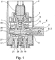
- a sanitary fitting which has a fitting body 1, for example made of plastic or brass.
- the fitting body 1 is arranged within a decorative sleeve 2.
- the sanitary fitting also has a mixing lever 3, which is pivotable about a rotation axis D, to set a mixed water temperature of the effluent from a not shown water outlet of the sanitary fitting mixed water.
- an infra-red actuable solenoid valve 5 is installed in the fitting body 1, which closes in a non-use state of the sanitary fitting a guided to the water outlet mixing water outlet 7. If an infrared sensor under the sanitary fitting water spout hands or the like detected, the valve 5 is opened, whereby the mixed water can flow out of the sanitary fitting water spout.
- the mixing lever 3 is attached to a mixing shaft 13 with the interposition of a temperature limiter 11 not described in detail. This is rotatably mounted in a hollow cylindrical mixing shaft bore 15 of the fitting body 1 about the rotation axis D.
- the sanitary fitting on its underside each have a cold water inlet 17 and a hot water inlet 19, which are connected to the water supply network and open into the mixing shaft bore 15 via inlet openings.
- the mixed water outlet 7 opens with respect to the axis of rotation D diametrically opposite to the two cold and hot water inlets 17, 19 in the mixing shaft bore 15.
- the mixing shaft 13 has the outer peripheral side on a control contour 21 which limits a mixing chamber 23.
- the mixing chamber 23 of the mixing shaft 13 may vary depending on its rotational position, a flow passage from the cold and hot water inlets 17,19 to the shaft-side mixing chamber 23. It can be in a in the FIG.
- the mixing shaft mixing chamber 23 may be fluidly decoupled from the cold water inlet 17. Conversely, in a cold water end position, not shown, the mixing shaft mixing chamber 23 may be fluidly decoupled from the hot water inlet 19.
- the hot water end position E is the fluidic decoupling to form a liquid-sealing valve gap 25 between a sealing surface 27 of the mixing shaft control contour 21 and the inner peripheral wall 29 of the mixing shaft bore 15 realized.
- the mouth openings of the mixed water outlet 7 and the cold and hot water inlets 17, 19 are in the FIG. 2 arranged within a wet area N.
- the wet area N is viewed in the axial direction on both sides to the outside by means of liquid seals 31 of axially outer dry areas T delimited.
- the two liquid seals 31 are in common practice as O-ring seals, which are in annular grooves 33 (FIG. Fig. 2 ) of the mixing shaft 13 are inserted and liquid-tight against the inner peripheral wall 29 press. Both the inner peripheral wall 29 and the annular grooves 33 are rotationally symmetrical with respect to the cylinder axis Z, which is coaxial with the axis of rotation D.
- the mixing shaft 13 is extended in each case in the dry areas T.
- a pressure element 35 is arranged, which is supported between the inner peripheral wall 29 of the fitting body 1 and the mixing shaft 13. By means of the pressure element 35, a pressure force F is generated with which the mixing shaft 13 is pressed with its control contour sealing surface 27 against the inner peripheral wall 29 of the mixing shaft bore 15 in order to reduce the valve gap 25.
- the pressure element 35 is a ring segment of an O-ring 37, which is made of an elastic elastomer material.
- the O-ring 37 is arranged in a circumferential, radially outwardly open annular groove 38 of the mixing shaft 13.
- the O-ring 37 in the installation position shown in the figures, is not circumferentially continuously pressurized, but only in the region of the ring segment 35, which in the Figures 2 and 3 diametrically opposite to the cold and hot water inlets 17, 19 is pressed.
- the force exerted on the valve gap 25 compressive force F builds up.
- the O-ring 37 is highlighted by cross-hatching. The cross-hatching is drawn in the compressed ring segment 35 of the O-ring 37 closer than in the subsequent to the ring segment 35 O-ring portion.
- the above-mentioned compression of the ring segment 35 of the O-ring 37 is in the Figures 2 and 3 realized by a support contour 39, at which the inner peripheral wall 29 has a cylinder radius r 1 .
- the cylinder radius r 1 is in the Fig. 3 by a radial offset ⁇ r ( Fig. 3 ) is smaller than the cylinder radius r 2 of inner circumferential wall portions adjacent thereto in the circumferential direction.
- ⁇ r Fig. 3
Landscapes
- Engineering & Computer Science (AREA)
- General Engineering & Computer Science (AREA)
- Mechanical Engineering (AREA)
- Multiple-Way Valves (AREA)
Abstract
Description
- Die Erfindung betrifft eine Sanitärarmatur mit einem Armaturenkörper nach dem Oberbegriff des Patentanspruches 1.
- Aus der
DE 10 2013 011 598 A1 ist eine gattungsgemäße Sanitärarmatur mit einem Armaturenkörper bekannt, der eine Mischwellenbohrung aufweist, in der eine benutzerseitig drehbetätigbare Mischwelle um eine Drehachse drehgelagert ist. In die Mischwellenbohrung münden ein Warmwasser-Einlass und ein Kaltwasser-Einlass sowie ein Mischwasser-Auslass. Die Mischwelle weist umfangsseitig eine Steuerkontur auf, die eine Mischkammer begrenzt. In Abhängigkeit von der benutzerseitig einstellbaren Mischwellen-Drehstellung können der Warmwasser-Einlass und/oder der Kaltwasser-Einlass strömungstechnisch über die wellenseitige Mischkammer mit dem Mischwasser-Auslass verbunden werden, um eine Mischwassertemperatur für das aus der Sanitärarmatur ausströmende Mischwasser einzustellen. Sofern die Mischwelle bis auf Anschlag in eine Warmwasser- oder Kaltwasser-Endstellung gedreht ist, ist die Mischwellen-Mischkammer von der Warm- oder Kaltwasser-Einlassöffnung strömungstechnisch entkoppelt, und zwar unter Bildung eines flüssigkeitsdichtenden Ventilspalts zwischen einer Dichtfläche der Mischwellen-Steuerkontur und einer Innenumfangswand der Mischwellenbohrung im Armaturenkörper. - Dieser Ventilspalt zwischen dem Warm- oder Kaltwasser-Einlass und der Mischkammer ist nicht hermetisch flüssigkeitsdicht, sondern vielmehr geringfügig flüssigkeitsdurchlässig, wodurch sich in der Warmwasser-/Kaltwasser-Endstellung ein sogenannter Querfluss durch den Ventilspalt bildet. Der Querfluss führt bei einer Kaltwasser-Endstellung der Mischwelle zu einer unerwünschten Temperaturerhöhung des aus der Sanitärarmatur ausströmenden Kaltwassers. Umgekehrt führt der Querfluss bei einer Warmwasser-Endstellung zu einer unerwünschten Temperatur-Reduzierung des aus der Sanitärarmatur ausströmenden Warmwassers.
- Üblicherweise wird sowohl der Armaturenkörper als auch die Mischwelle aus einem Metall, zum Beispiel Messing, hergestellt. In diesem Fall kann die Mischwelle in einer engen Passung in der Mischwellenbohrung des Armaturenkörpers drehgelagert sein, und zwar mit entsprechend reduziertem Querfluss. Die enge Passung zwischen der Mischwelle und der Armaturenkörper-Mischwellenbohrung wird durch eine Spanbearbeitung in fertigungstechnisch aufwendiger Weise realisiert, so dass sich ein Bauteil-Spiel in einem Bereich von 1/100-Milimetern ergibt.
- Speziell bei einer Kunststoff-Fertigung besteht die Problematik, dass sich die Bauteil-Toleranz zwischen dem Armaturenkörper und der Mischwelle erhöht, wodurch sich auch das Spaltmaß des flüssigkeitsdichtenden Ventilspalts zwischen der Warm- oder Kaltwasser-Einlassöffnung und der Mischkammer erhöht. Dies führt wiederum zu einem nachteilig großen Querfluss.
- Die Aufgabe der Erfindung besteht darin, eine Sanitärarmatur bereitzustellen, bei der die Funktionsfähigkeit der Sanitärarmatur in einfacher Weise erhöht ist.
- Die Aufgabe ist durch die Merkmale des Patentanspruches 1 gelöst. Bevorzugte Weiterbildungen der Erfindung sind in den Unteransprüchen offenbart.
- Die Erfindung beruht auf dem Sachverhalt, dass sich bei einer Bauteil-Fertigung mit größeren Bauteil-Toleranzen zwangsläufig auch der Querfluss erhöht. Vor diesem Hintergrund weist die Sanitärarmatur zumindest ein zwischen dem Armaturenkörper und der Mischwelle wirkendes Druckelement auf, das die Steuerkontur-Dichtfläche der Mischwelle gegen die Innenumfangswand der Mischwellenbohrung (nachfolgend auch als hohlzylindrischer Mischwellenraum bezeichnet) drückt, und zwar mit einer vordefinierten Druckkraft sowie unter Reduzierung des Ventilspalts zwischen der Mischwellen-Dichtfläche und der Innenumfangswand der Mischwellenbohrung.
- Eine einfache sowie wirkungsvolle Druckkraft-Beaufschlagung des Ventilspalts ist für die Funktionsfähigkeit der Erfindung von großer Bedeutung. Vor diesem Hintergrund kann das Druckelement mit Bezug auf die Mischwelle diametral gegenüberliegend zu den Einlassöffnungen der Warm- und Kaltwasser-Einlässe angeordnet sein. Im Hinblick auf eine möglichst hermetische Abdichtung des Ventilspalts ist es bevorzugt, wenn die vom Druckelement ausgeübte Druckkraft, in der Umfangsrichtung betrachtet, lokal begrenzt nur auf den Ventilspalt wirkt, das heißt nicht in der Umfangsrichtung durchgängig gegen die Innenumfangswand des hohlzylindrischen Mischwellenraums wirkt.
- In einer besonders einfachen sowie wirkungsvollen Ausführungsform kann das Druckelement als ein Ringsegment eines O-Ringes realisiert sein. Der O-Ring kann ein einfacher Dichtring zum Beispiel aus einem Elastomermaterial sein, wie er ansonsten in üblicher Weise zur Abdichtung zwischen der Mischwelle und der Mischwellenbohrung im Armaturenkörper eingesetzt wird. Von daher kann der O-Ring im unverformten Fertigungszustand einen umfangsseitig durchgängig konstanten kreisflächenförmigen Querschnitt aufweisen.
- Der als Druckelement wirkende O-Ring kann in einer umlaufenden, radial nach außen offenen Ringnut der Mischwelle angeordnet sein. Damit die oben angegebene Druckkraft im O-Ring aufgebaut werden kann, ist es erforderlich, dass das zu den Einlassöffnungen diametral gegenüberliegende Ringsegment des O-Rings zwischen der Innenumfangswand der Mischwellenbohrung und der Mischwelle verpresst ist, wodurch sich die Druckkraft aufbaut.
- Die oben erwähnte Verpressung des Ringsegmentes des O-Rings kann in folgender Weise technisch besonders einfach umgesetzt werden: So kann die Innenumfangswand der Mischwellenbohrung mit einer zusätzlichen Stützkontur ausgebildet sein. Die Raumverhältnisse zwischen Stützkontur und der in der Mischwellenbohrung drehgelagerten Mischwelle können so ausgelegt sein, dass das Ringsegment des O-Rings von der Stützkontur gegen Nutgrund der umlaufenden Mischwellen-Ringnut gedrückt wird, wodurch sich die auf den Ventilspalt wirkende Druckkraft aufbaut. Die Wirkungslinie der erzeugten Druckkraft verläuft - auch bei Drehbetätigung der Mischwelle - stets durch die Mischwellen-Drehachse sowie durch den Ventilspalt.
- Wie oben erwähnt, bewirkt die an der Innenumfangswand ausgebildete Stützkontur das Verpressen des Ringsegmentes des O-Rings. Für ein wirkungsvolles Verpressen ist es bevorzugt, wenn die Stützkontur in radialer Flucht zum Ringsegment des O-Rings sowie zu dessen Mischwellen-Ringnut angeordnet ist. Zudem kann, in einer zur Drehachse rechtwinkligen Schnittebene betrachtet, die Innenumfangswand an der Stützkontur einen Zylinderradius aufweisen, der im Vergleich zum Zylinderradius von daran in Umfangsrichtung angrenzenden Innenumfangswand-Abschnitten reduziert ist.
- In einer technischen Umsetzung kann die Ringnut, insbesondere deren Nutgrund, in der Umfangsrichtung durchgängig rotationssymmetrisch zur Mischwellen-Drehachse sein. Zusätzlich kann die Innenumfangswand des Armaturenkörpers rotationssymmetrisch zur Zylinderachse der Mischwellenbohrung sein, und zwar mit Ausnahme der oben erwähnten Stützkontur an der Innenumfangswand. Die Zylinderachse und die Mischwellen-Drehachse sind dabei zueinander koaxial ausgerichtet.
- Die Auslassöffnung des Mischwasser-Auslasses und die Einlassöffnungen der Kalt- und Warmwasser-Einlässe sind in der Sanitärarmatur innerhalb eines Nassbereiches der Mischwellenbohrung im Armaturenkörper angeordnet. Der Nassbereich ist in der Axialrichtung üblicherweise beidseitig nach außen mittels Flüssigkeitsdichtungen, das heißt mit Hilfe von O-Ringdichtungen, von Trockenbereichen abgegrenzt. Die O-Ringdichtungen verlaufen ebenfalls in Mischwellen-Ringnuten, wobei die O-Ringdichtungen in der Umfangsrichtung in etwa mit gleichmäßiger Anpresskraft gegen die radial äußere Innenumfangswand der Mischwellenbohrung flüssigkeitsdicht gedrückt sind. Das erfindungsgemäße Druckelement ist bevorzugt nicht im Nassbereich, sondern vielmehr in der Axialrichtung außerhalb der Flüssigkeitsdichtungen in den Trockenbereichen angeordnet.
- Die vorstehend erläuterten und/oder in den Unteransprüchen wiedergegebenen vorteilhaften Aus- und/oder Weiterbildungen der Erfindung können - außer zum Beispiel in den Fällen eindeutiger Abhängigkeiten oder unvereinbarer Alternativen - einzeln oder aber auch in beliebiger Kombination miteinander zur Anwendung kommen.
- Die Erfindung und ihre vorteilhaften Aus- und Weiterbildungen sowie deren Vorteile werden nachfolgend anhand von Zeichnungen näher erläutert.
- Es zeigen:
- Figur 1
- in einer Teilschnittdarstellung eine Sanitärarmatur;
- Figur 2
- eine Detailansicht aus der
Figur 1 ; und - Figur 3
- eine Schnittdarstellung entlang der Schnittebene A-A aus der
Figur 2 . - In der
Figur 1 ist eine Sanitärarmatur gezeigt, die einen Armaturenkörper 1, zum Beispiel aus Kunststoff oder aus Messing, aufweist. Der Armaturenkörper 1 ist innerhalb einer Dekorhülse 2 angeordnet. Die Sanitärarmatur weist außerdem einen Mischhebel 3 auf, der um eine Drehachse D schwenkbar ist, um eine Mischwassertemperatur des aus einem nicht gezeigten Wasser-Auslauf der Sanitärarmatur ausströmenden Mischwassers einzustellen. Zudem ist im Armaturenkörper 1 ein infrarotbetätigbares Magnetventil 5 verbaut, das in einem Nichtgebrauchszustand der Sanitärarmatur einen zum Wasser-Auslauf geführten Mischwasser-Auslass 7 schließt. Sofern ein Infrarotsensor unter dem Sanitärarmatur-Wasser-Auslauf Hände oder dergleichen erfasst, wird das Ventil 5 geöffnet, wodurch das Mischwasser aus dem Sanitärarmatur-Wasser-Auslauf ausströmen kann. - Der Mischhebel 3 ist unter Zwischenschaltung eines nicht näher beschriebenen Temperaturbegrenzers 11 an einer Mischwelle 13 befestigt. Diese ist in einer hohlzylindrischen Mischwellenbohrung 15 des Armaturenkörpers 1 um die Drehachse D drehgelagert.
- Wie aus der
Figur 1 hervorgeht, weist die Sanitärarmatur an ihrer Unterseite jeweils einen Kaltwasser-Einlass 17 und einen Warmwasser-Einlass 19 auf, die mit dem Wasserversorgungsnetz verbunden sind und über Einlassöffnungen in die Mischwellenbohrung 15 münden. Der Mischwasser-Auslass 7 mündet mit Bezug auf die Drehachse D diametral gegenüberliegend zu den beiden Kalt- und Warmwasser-Einlässen 17, 19 in die Mischwellenbohrung 15. Die Mischwelle 13 weist außenumfangsseitig eine Steuerkontur 21 auf, die eine Mischkammer 23 begrenzt. Die Mischkammer 23 der Mischwelle 13 kann in Abhängigkeit von ihrer Drehstellung einen Strömungsdurchlass von den Kalt- und Warmwasser-Einlässen 17,19 zur wellenseitigen Mischkammer 23 variieren. Dabei kann in einer in derFigur 1 oder2 gezeigten Warmwasser-Endstellung E die Mischwellen-Mischkammer 23 von dem Kaltwasser-Einlass 17 strömungstechnisch entkoppelt sein. Umgekehrt kann in einer nicht gezeigten Kaltwasser-Endstellung die Mischwellen-Mischkammer 23 von dem Warmwasser-Einlass 19 strömungstechnisch entkoppelt sein. In der in derFigur 1 gezeigten Warmwasser-Endstellung E ist die strömungstechnische Entkopplung unter Bildung eines flüssigkeitsdichtenden Ventilspaltes 25 zwischen einer Dichtfläche 27 der Mischwellen-Steuerkontur 21 und der Innenumfangswand 29 der Mischwellenbohrung 15 realisiert. - Die Mündungsöffnungen des Mischwasser-Auslasses 7 sowie der Kalt- und Warmwasser-Einlässe 17, 19 sind in der
Figur 2 innerhalb eines Nassbereiches N angeordnet. Der Nassbereich N ist in der Axialrichtung betrachtet beidseitig nach außen mittels Flüssigkeitsdichtungen 31 von axial äußeren Trockenbereichen T abgegrenzt. Die beiden Flüssigkeitsdichtungen 31 sind in gängiger Praxis als O-Ringdichtungen ausgeführt, die in Ringnuten 33 (Fig. 2 ) der Mischwelle 13 eingesetzt sind und flüssigkeitsdicht gegen die Innenumfangswand 29 drücken. Sowohl die Innenumfangswand 29 als auch die Ringnuten 33 sind mit Bezug auf die Zylinderachse Z, die zur Drehachse D koaxial liegt, rotationssymmetrisch ausgebildet. - Axial beidseitig außerhalb der beiden Flüssigkeitsdichtungen 31 ist die Mischwelle 13 jeweils in die Trockenbereiche T verlängert. In jedem der Trockenbereiche T ist jeweils ein Druckelement 35 angeordnet, das zwischen der Innenumfangswand 29 des Armaturenkörpers 1 und der Mischwelle 13 abgestützt ist. Mittels des Druckelements 35 wird eine Druckkraft F erzeugt, mit der die Mischwelle 13 mit ihrer Steuerkontur-Dichtfläche 27 gegen die Innenumfangswand 29 der Mischwellenbohrung 15 gedrückt wird, um den Ventilspalt 25 zu reduzieren.
- In dem gezeigten Ausführungsbeispiel ist das Druckelement 35 ein Ringsegment eines O-Rings 37, der aus einem elastischen Elastomermaterial gefertigt ist. Der O-Ring 37 ist in einer umlaufenden, radial nach außen offenen Ringnut 38 der Mischwelle 13 angeordnet. Im Unterschied zu einer herkömmlichen O-Ringdichtung ist der O-Ring 37 (in der in den Figuren gezeigten Einbaulage) nicht umfangsseitig durchgängig druckbeaufschlagt, sondern lediglich im Bereich des Ringsegments 35, das in den
Figuren 2 und3 diametral gegenüberliegend zu den Kalt- und Warmwasser-Einlässen 17, 19 verpresst ist. Durch die Verpressung des Ringsegments 35 baut sich die auf den Ventilspalt 25 ausgeübte Druckkraft F auf. In derFig. 3 ist der O-Ring 37 durch eine Kreuzschraffur hervorgehoben. Die Kreuzschraffur ist im verpressten Ringsegment 35 des O-Rings 37 enger gezeichnet als in dem an das Ringsegment 35 anschließenden O-Ring-Anteil. - Die oben erwähnte Verpressung des Ringsegmentes 35 des O-Rings 37 ist in den
Figuren 2 und3 durch eine Stützkontur 39 realisiert, an der die Innenumfangswand 29 einen Zylinderradius r1 aufweist. Der Zylinderradius r1 ist in derFig. 3 um einen Radialversatz Δr (Fig. 3 ) kleiner bemessen als der Zylinderradius r2 von daran in der Umfangsrichtung angrenzenden Innenumfangswand-Abschnitten. In Umfangsrichtung außerhalb der Stützkontur 39 ist der O-Ring 37 somit nicht verpresst, sondern vielmehr überhaupt nicht oder nur geringfügig druckbeaufschlagt. - Auf diese Weise kann in der gezeigten Warmwasser-Endstellung E ein Querfluss q (
Fig. 2 ) durch den flüssigkeitsdichtenden Ventilspalt 25 zwischen der Steuerkontur-Dichtfläche 27 und der Innenumfangswand 29 weiter reduziert oder sogar verhindert werden, und zwar trotz größerer Bauteiltoleranzen zwischen Mischwelle 13 und der Mischwellenbohrung 15. -
- 1
- Armaturenkörper
- 2
- Dekorhülse
- 3
- Mischhebel
- 5
- Ventil
- 7
- Mischwasser-Auslass
- 11
- Temperaturbegrenzer
- 13
- Mischwelle
- 15
- hohlzylindrischer Mischwellenraum bzw. Mischwellenbohrung
- 17, 19
- Kalt- und Warmwasser-Einlässe
- 21
- Steuerkontur
- 23
- Mischkammer
- 25
- Ventilspalt
- 27
- Dichtfläche
- 29
- Innenumfangswand
- 31
- Flüssigkeitsdichtungen
- 35
- Druckelement
- 36
- Nutgrund
- 37
- O-Ring
- 38
- Ringnut
- 39
- Stützkontur
- D
- Mischwellen-Drehachse
- Z
- Zylinder-Achse
- E
- Warmwasser-Endstellung
- N, T
- Nass- und Trockenbereiche
- q
- Querfluss
- r1, r2
- Radien
- Δr
- Radialversatz
Claims (10)
- Sanitärarmatur mit einem Armaturenkörper (1), mit einem hohlzylindrischen Mischwellenraum (15), in dem eine benutzerseitig drehbetätigbare Mischwelle (13) um eine Drehachse (D) drehgelagert ist, wobei in den hohlzylindrischen Mischwellenraum (15) ein Warmwasser-Einlass (19) und ein Kaltwasser-Einlass (17) sowie ein Mischwasser-Auslass (7) münden, und wobei die Mischwelle (13) außenumfangsseitig eine Steuerkontur (21) aufweist, die eine Mischkammer (23) begrenzt, die in Abhängigkeit von der Mischwellen-Drehstellung den Warmwasser-Einlass (19) und/oder den Kaltwasser-Einlass (17) strömungstechnisch mit dem Mischwasser-Auslass (7) verbindet, um eine Mischwassertemperatur einzustellen, wobei in zumindest einer Mischwellen-Endstellung (E) die Mischwellen-Mischkammer (23) von der Warm- oder Kaltwasser-Einlassöffnung strömungstechnisch entkoppelt ist, und zwar unter Bildung eines flüssigkeitsdichtenden Ventilspalts (25) zwischen einer Dichtfläche (27) der Mischwellen-Steuerkontur (21) und der Innenumfangswand (29) des hohlzylindrischen Mischwellenraums (15), dadurch gekennzeichnet, dass die Sanitärarmatur zumindest ein zwischen dem Armaturenkörper (1) und der Mischwelle (13) wirkendes Druckelement (35) aufweist, das die Mischwelle (13) mit seiner Steuerkontur-Dichtfläche (27) gegen die Innenumfangswand (29) des hohlzylindrischen Mischwellenraums (15) drückt, und zwar mit einer Druckkraft (F) sowie unter Reduzierung des Ventilspalts (25).
- Sanitärarmatur nach Anspruch 1, dadurch gekennzeichnet, dass das Druckelement (35) mit Bezug auf die Mischwelle (13) diametral gegenüberliegend zu den Einlassöffnungen der Warm- und Kaltwasser-Einlässe (17, 19) angeordnet ist.
- Sanitärarmatur nach Anspruch 1 oder 2, dadurch gekennzeichnet, dass das Druckelement (35) als ein Ringsegment eines O-Rings (37), insbesondere aus Elastomermaterial, realisiert ist, und dass der O-Ring (37) in einer umlaufenden, radial nach außen offenen Ringnut (38) der Mischwelle (13) angeordnet ist, und dass insbesondere das Ringsegment (35) des O-Rings (37) mit Bezug auf die Mischwelle (13) diametral gegenüberliegend zu den Einlassöffnungen bzw. zum Ventilspalt (25) angeordnet ist und/oder dass das Ringsegment (35) zwischen der Innenumfangswand (29) des hohlzylindrischen Mischwellenraums (15) und der Mischwelle (13) verpresst ist, und zwar unter Aufbau der Druckkraft (F), und dass insbesondere der in der Umfangsrichtung an das Ringsegment (35) anschließende O-Ring-Anteil nicht oder nur geringfügig verpresst bzw. druckbeaufschlagt ist.
- Sanitärarmatur nach einem der Ansprüche 1, 2 oder 3, dadurch gekennzeichnet, dass vom Druckelement (35) ausgeübte Druckkraft (F), in der Umfangsrichtung betrachtet, lokal begrenzt nur auf den Ventilspalt (25) wirkt, und nicht in Umfangsrichtung durchgängig wirkt.
- Sanitärarmatur nach Anspruch 3 oder 4, dadurch gekennzeichnet, dass zur Verpressung des Ringsegments (35) des O-Rings (37) die Innenumfangswand (29) des hohlzylindrischen Mischwellenraums (15) eine Stützkontur (39) aufweist, und dass die Stützkontur (39) das Ringsegment (35) des O-Rings (37) gegen einen Nutgrund (36) der umlaufenden Mischwellen-Ringnut (37) drückt, und zwar unter Aufbau der auf den Ventilspalt (25) wirkenden Druckkraft (F).
- Sanitärarmatur nach Anspruch 4 oder 5, dadurch gekennzeichnet, dass die an der Innenumfangswand (29) des hohlzylindrischen Mischwellenraums (15) ausgebildete Stützkontur (39) in radialer Flucht zum Ringsegment (35) des O-Rings (37) sowie zu dessen Mischwellen-Ringnut (38) angeordnet ist.
- Sanitärarmatur nach einem der Ansprüche 3 bis 6, dadurch gekennzeichnet, dass in einem zur Mischwellen-Drehachse (D) rechtwinkligen Querschnitt (A-A) betrachtet die Innenumfangswand (29) an der Stützkontur (39) einen Zylinderradius (r1) aufweist, der im Vergleich zum Zylinderradius (r2) von an die Stützkontur (39) in Umfangsrichtung angrenzenden Innenumfangswand-Abschnitten um einen Radialversatz (Δr) reduziert ist.
- Sanitärarmatur nach einem der Ansprüche 3 bis 7, dadurch gekennzeichnet, dass die Ringnut (38), insbesondere deren Nutgrund (36), rotationssymmetrisch zur Mischwellen-Drehachse (D) ist, und/oder dass die Innenumfangswand (29) rotationssymmetrisch zur Zylinderachse (Z) des hohlzylindrischen Mischwellenraums (15) ist, und zwar mit Ausnahme der Stützkontur (39) an der Innenumfangswand (29), und/oder dass die Zylinderachse (Z) und die Mischwellen-Drehachse (D) zueinander koaxial sind.
- Sanitärarmatur nach einem der Ansprüche 3 bis 8, dadurch gekennzeichnet, dass der O-Ring (37) im unverformten Fertigungszustand einen umfangsseitig durchgängig konstanten Querschnitt aufweist.
- Sanitärarmatur nach einem der vorhergehenden Ansprüche, dadurch gekennzeichnet, dass die Auslassöffnung des Mischwasser-Auslasses (7) und die Einlassöffnungen der Kalt- und Warmwasser-Einlässe (17, 19) in einem Nassbereich (N) des hohlzylindrischen Mischwellenraums (15) angeordnet sind, und dass der Nassbereich (N) in der Axialrichtung beidseitig nach außen mittels Flüssigkeitsdichtungen (31), insbesondere O-Ringdichtungen, von Trockenbereichen (T) abgegrenzt ist, und dass das Druckelement (35) in zumindest einem der Trockenbereiche (T) angeordnet ist.
Applications Claiming Priority (1)
| Application Number | Priority Date | Filing Date | Title |
|---|---|---|---|
| DE102016008000.0A DE102016008000A1 (de) | 2016-07-01 | 2016-07-01 | Sanitärarmatur |
Publications (2)
| Publication Number | Publication Date |
|---|---|
| EP3263959A1 true EP3263959A1 (de) | 2018-01-03 |
| EP3263959B1 EP3263959B1 (de) | 2020-05-27 |
Family
ID=59227433
Family Applications (1)
| Application Number | Title | Priority Date | Filing Date |
|---|---|---|---|
| EP17001084.7A Active EP3263959B1 (de) | 2016-07-01 | 2017-06-26 | Sanitärarmatur |
Country Status (3)
| Country | Link |
|---|---|
| US (1) | US10648578B2 (de) |
| EP (1) | EP3263959B1 (de) |
| DE (1) | DE102016008000A1 (de) |
Citations (4)
| Publication number | Priority date | Publication date | Assignee | Title |
|---|---|---|---|---|
| SU1229492A1 (ru) * | 1983-09-15 | 1986-05-07 | Всесоюзный Научно-Исследовательский Институт По Сбору,Подготовке И Транспорту Нефти И Нефтепродуктов | Трехходовой переключатель потока |
| WO2001086179A1 (en) * | 2000-05-12 | 2001-11-15 | Esbe Ab | Mixing valve |
| EP2759747A1 (de) * | 2013-01-29 | 2014-07-30 | Esbe AB | Flüssigkeitsventil |
| DE102013011598A1 (de) | 2013-07-11 | 2015-01-15 | Grohe Ag | Sanitärarmatur mit Mischwelle |
Family Cites Families (1)
| Publication number | Priority date | Publication date | Assignee | Title |
|---|---|---|---|---|
| US4171711A (en) * | 1975-12-02 | 1979-10-23 | Rockwell International Corporation | Plug valve construction |
-
2016
- 2016-07-01 DE DE102016008000.0A patent/DE102016008000A1/de not_active Withdrawn
-
2017
- 2017-06-26 EP EP17001084.7A patent/EP3263959B1/de active Active
- 2017-06-30 US US15/639,635 patent/US10648578B2/en not_active Expired - Fee Related
Patent Citations (4)
| Publication number | Priority date | Publication date | Assignee | Title |
|---|---|---|---|---|
| SU1229492A1 (ru) * | 1983-09-15 | 1986-05-07 | Всесоюзный Научно-Исследовательский Институт По Сбору,Подготовке И Транспорту Нефти И Нефтепродуктов | Трехходовой переключатель потока |
| WO2001086179A1 (en) * | 2000-05-12 | 2001-11-15 | Esbe Ab | Mixing valve |
| EP2759747A1 (de) * | 2013-01-29 | 2014-07-30 | Esbe AB | Flüssigkeitsventil |
| DE102013011598A1 (de) | 2013-07-11 | 2015-01-15 | Grohe Ag | Sanitärarmatur mit Mischwelle |
Also Published As
| Publication number | Publication date |
|---|---|
| US20180003308A1 (en) | 2018-01-04 |
| US10648578B2 (en) | 2020-05-12 |
| DE102016008000A1 (de) | 2018-01-04 |
| EP3263959B1 (de) | 2020-05-27 |
Similar Documents
| Publication | Publication Date | Title |
|---|---|---|
| DE2150825B2 (de) | Geräuscharmer Wasserhahn | |
| DE102008056245A1 (de) | Thermostatventil | |
| WO2008125267A1 (de) | Hochdruckreinigungsgerät | |
| DE10324307B3 (de) | Schnellkupplungseinheit mit integriertem Rückschlagventil | |
| DE3991752C2 (de) | Kartusche für einen Einhebelmischhahn mit durch elastische Mittel verstärkten Verbindungsrohren | |
| DE4224664C2 (de) | Rotordüse | |
| EP1707692A1 (de) | Sanitärarmatur mit teleskopierbarem Auslaufsystem | |
| EP3064657A1 (de) | Sanitärarmatur | |
| EP3263959B1 (de) | Sanitärarmatur | |
| WO2015117768A1 (de) | Armatur mit einem schwenkauslauf | |
| DE2755765C2 (de) | ||
| DE10052505B4 (de) | Unterflurhydrant mit rohrförmigem Ventilsitzring | |
| DE102019120226A1 (de) | Ventil und Vorrichtung zur Regelung von Drücken eines Strömungsmittels mit dem Ventil sowie Vorrichtung zur Sicherung des Ventils in dem Getriebebauteil | |
| DE102004058692B4 (de) | Magnetventil | |
| DE202005002152U1 (de) | Membranventil | |
| DE102019120224A1 (de) | Ventil und Vorrichtung zur Regelung von Drücken eines Strömungsmittels mit dem Ventil sowie Vorrichtung zur Sicherung des Ventils in dem Getriebebauteil | |
| DE10258832B4 (de) | Ventil | |
| EP1503121B1 (de) | Schlauchbruch-Ventil | |
| EP1703185B1 (de) | Coaxialventil | |
| DE3015873A1 (de) | Automatisches zeitsteuerventil zur wasserabgabesteuerung in bewaesserungsanlagen | |
| CH633624A5 (de) | Gleitringdichtung. | |
| DE102019120227A1 (de) | Ventil und Vorrichtung zur Regelung von Drücken eines Strömungsmittels mit dem Ventil sowie Vorrichtung zur Sicherung des Ventils in dem Getriebebauteil | |
| DE1951183C (de) | Schieberventil mit einer Einrichtung zum Einstellen des Dichtungsdruckes am Verschluß teil | |
| AT411186B (de) | Einschraubventil | |
| DE4121439A1 (de) | Verbesserungen in einem kugelventil fuer fluide |
Legal Events
| Date | Code | Title | Description |
|---|---|---|---|
| PUAI | Public reference made under article 153(3) epc to a published international application that has entered the european phase |
Free format text: ORIGINAL CODE: 0009012 |
|
| STAA | Information on the status of an ep patent application or granted ep patent |
Free format text: STATUS: THE APPLICATION HAS BEEN PUBLISHED |
|
| AK | Designated contracting states |
Kind code of ref document: A1 Designated state(s): AL AT BE BG CH CY CZ DE DK EE ES FI FR GB GR HR HU IE IS IT LI LT LU LV MC MK MT NL NO PL PT RO RS SE SI SK SM TR |
|
| AX | Request for extension of the european patent |
Extension state: BA ME |
|
| STAA | Information on the status of an ep patent application or granted ep patent |
Free format text: STATUS: REQUEST FOR EXAMINATION WAS MADE |
|
| 17P | Request for examination filed |
Effective date: 20180703 |
|
| RBV | Designated contracting states (corrected) |
Designated state(s): AL AT BE BG CH CY CZ DE DK EE ES FI FR GB GR HR HU IE IS IT LI LT LU LV MC MK MT NL NO PL PT RO RS SE SI SK SM TR |
|
| GRAP | Despatch of communication of intention to grant a patent |
Free format text: ORIGINAL CODE: EPIDOSNIGR1 |
|
| STAA | Information on the status of an ep patent application or granted ep patent |
Free format text: STATUS: GRANT OF PATENT IS INTENDED |
|
| RIC1 | Information provided on ipc code assigned before grant |
Ipc: E03C 1/00 20060101ALI20200227BHEP Ipc: F16K 11/076 20060101AFI20200227BHEP Ipc: F16K 11/085 20060101ALI20200227BHEP Ipc: F16K 27/06 20060101ALI20200227BHEP |
|
| GRAS | Grant fee paid |
Free format text: ORIGINAL CODE: EPIDOSNIGR3 |
|
| INTG | Intention to grant announced |
Effective date: 20200325 |
|
| GRAA | (expected) grant |
Free format text: ORIGINAL CODE: 0009210 |
|
| STAA | Information on the status of an ep patent application or granted ep patent |
Free format text: STATUS: THE PATENT HAS BEEN GRANTED |
|
| AK | Designated contracting states |
Kind code of ref document: B1 Designated state(s): AL AT BE BG CH CY CZ DE DK EE ES FI FR GB GR HR HU IE IS IT LI LT LU LV MC MK MT NL NO PL PT RO RS SE SI SK SM TR |
|
| REG | Reference to a national code |
Ref country code: GB Ref legal event code: FG4D Free format text: NOT ENGLISH |
|
| REG | Reference to a national code |
Ref country code: CH Ref legal event code: EP |
|
| REG | Reference to a national code |
Ref country code: DE Ref legal event code: R096 Ref document number: 502017005408 Country of ref document: DE |
|
| REG | Reference to a national code |
Ref country code: AT Ref legal event code: REF Ref document number: 1274898 Country of ref document: AT Kind code of ref document: T Effective date: 20200615 |
|
| REG | Reference to a national code |
Ref country code: FI Ref legal event code: FGE |
|
| REG | Reference to a national code |
Ref country code: LT Ref legal event code: MG4D |
|
| PG25 | Lapsed in a contracting state [announced via postgrant information from national office to epo] |
Ref country code: NO Free format text: LAPSE BECAUSE OF FAILURE TO SUBMIT A TRANSLATION OF THE DESCRIPTION OR TO PAY THE FEE WITHIN THE PRESCRIBED TIME-LIMIT Effective date: 20200827 Ref country code: GR Free format text: LAPSE BECAUSE OF FAILURE TO SUBMIT A TRANSLATION OF THE DESCRIPTION OR TO PAY THE FEE WITHIN THE PRESCRIBED TIME-LIMIT Effective date: 20200828 Ref country code: LT Free format text: LAPSE BECAUSE OF FAILURE TO SUBMIT A TRANSLATION OF THE DESCRIPTION OR TO PAY THE FEE WITHIN THE PRESCRIBED TIME-LIMIT Effective date: 20200527 Ref country code: PT Free format text: LAPSE BECAUSE OF FAILURE TO SUBMIT A TRANSLATION OF THE DESCRIPTION OR TO PAY THE FEE WITHIN THE PRESCRIBED TIME-LIMIT Effective date: 20200928 Ref country code: IS Free format text: LAPSE BECAUSE OF FAILURE TO SUBMIT A TRANSLATION OF THE DESCRIPTION OR TO PAY THE FEE WITHIN THE PRESCRIBED TIME-LIMIT Effective date: 20200927 Ref country code: SE Free format text: LAPSE BECAUSE OF FAILURE TO SUBMIT A TRANSLATION OF THE DESCRIPTION OR TO PAY THE FEE WITHIN THE PRESCRIBED TIME-LIMIT Effective date: 20200527 |
|
| REG | Reference to a national code |
Ref country code: NL Ref legal event code: MP Effective date: 20200527 |
|
| PG25 | Lapsed in a contracting state [announced via postgrant information from national office to epo] |
Ref country code: RS Free format text: LAPSE BECAUSE OF FAILURE TO SUBMIT A TRANSLATION OF THE DESCRIPTION OR TO PAY THE FEE WITHIN THE PRESCRIBED TIME-LIMIT Effective date: 20200527 Ref country code: HR Free format text: LAPSE BECAUSE OF FAILURE TO SUBMIT A TRANSLATION OF THE DESCRIPTION OR TO PAY THE FEE WITHIN THE PRESCRIBED TIME-LIMIT Effective date: 20200527 Ref country code: LV Free format text: LAPSE BECAUSE OF FAILURE TO SUBMIT A TRANSLATION OF THE DESCRIPTION OR TO PAY THE FEE WITHIN THE PRESCRIBED TIME-LIMIT Effective date: 20200527 Ref country code: BG Free format text: LAPSE BECAUSE OF FAILURE TO SUBMIT A TRANSLATION OF THE DESCRIPTION OR TO PAY THE FEE WITHIN THE PRESCRIBED TIME-LIMIT Effective date: 20200827 |
|
| PG25 | Lapsed in a contracting state [announced via postgrant information from national office to epo] |
Ref country code: AL Free format text: LAPSE BECAUSE OF FAILURE TO SUBMIT A TRANSLATION OF THE DESCRIPTION OR TO PAY THE FEE WITHIN THE PRESCRIBED TIME-LIMIT Effective date: 20200527 Ref country code: NL Free format text: LAPSE BECAUSE OF FAILURE TO SUBMIT A TRANSLATION OF THE DESCRIPTION OR TO PAY THE FEE WITHIN THE PRESCRIBED TIME-LIMIT Effective date: 20200527 |
|
| PG25 | Lapsed in a contracting state [announced via postgrant information from national office to epo] |
Ref country code: RO Free format text: LAPSE BECAUSE OF FAILURE TO SUBMIT A TRANSLATION OF THE DESCRIPTION OR TO PAY THE FEE WITHIN THE PRESCRIBED TIME-LIMIT Effective date: 20200527 Ref country code: CZ Free format text: LAPSE BECAUSE OF FAILURE TO SUBMIT A TRANSLATION OF THE DESCRIPTION OR TO PAY THE FEE WITHIN THE PRESCRIBED TIME-LIMIT Effective date: 20200527 Ref country code: ES Free format text: LAPSE BECAUSE OF FAILURE TO SUBMIT A TRANSLATION OF THE DESCRIPTION OR TO PAY THE FEE WITHIN THE PRESCRIBED TIME-LIMIT Effective date: 20200527 Ref country code: EE Free format text: LAPSE BECAUSE OF FAILURE TO SUBMIT A TRANSLATION OF THE DESCRIPTION OR TO PAY THE FEE WITHIN THE PRESCRIBED TIME-LIMIT Effective date: 20200527 Ref country code: SM Free format text: LAPSE BECAUSE OF FAILURE TO SUBMIT A TRANSLATION OF THE DESCRIPTION OR TO PAY THE FEE WITHIN THE PRESCRIBED TIME-LIMIT Effective date: 20200527 Ref country code: IT Free format text: LAPSE BECAUSE OF FAILURE TO SUBMIT A TRANSLATION OF THE DESCRIPTION OR TO PAY THE FEE WITHIN THE PRESCRIBED TIME-LIMIT Effective date: 20200527 Ref country code: DK Free format text: LAPSE BECAUSE OF FAILURE TO SUBMIT A TRANSLATION OF THE DESCRIPTION OR TO PAY THE FEE WITHIN THE PRESCRIBED TIME-LIMIT Effective date: 20200527 |
|
| REG | Reference to a national code |
Ref country code: CH Ref legal event code: PL |
|
| PG25 | Lapsed in a contracting state [announced via postgrant information from national office to epo] |
Ref country code: SK Free format text: LAPSE BECAUSE OF FAILURE TO SUBMIT A TRANSLATION OF THE DESCRIPTION OR TO PAY THE FEE WITHIN THE PRESCRIBED TIME-LIMIT Effective date: 20200527 Ref country code: MC Free format text: LAPSE BECAUSE OF FAILURE TO SUBMIT A TRANSLATION OF THE DESCRIPTION OR TO PAY THE FEE WITHIN THE PRESCRIBED TIME-LIMIT Effective date: 20200527 Ref country code: PL Free format text: LAPSE BECAUSE OF FAILURE TO SUBMIT A TRANSLATION OF THE DESCRIPTION OR TO PAY THE FEE WITHIN THE PRESCRIBED TIME-LIMIT Effective date: 20200527 |
|
| REG | Reference to a national code |
Ref country code: DE Ref legal event code: R097 Ref document number: 502017005408 Country of ref document: DE |
|
| PG25 | Lapsed in a contracting state [announced via postgrant information from national office to epo] |
Ref country code: LU Free format text: LAPSE BECAUSE OF NON-PAYMENT OF DUE FEES Effective date: 20200626 |
|
| PLBE | No opposition filed within time limit |
Free format text: ORIGINAL CODE: 0009261 |
|
| STAA | Information on the status of an ep patent application or granted ep patent |
Free format text: STATUS: NO OPPOSITION FILED WITHIN TIME LIMIT |
|
| PG25 | Lapsed in a contracting state [announced via postgrant information from national office to epo] |
Ref country code: LI Free format text: LAPSE BECAUSE OF NON-PAYMENT OF DUE FEES Effective date: 20200630 Ref country code: CH Free format text: LAPSE BECAUSE OF NON-PAYMENT OF DUE FEES Effective date: 20200630 Ref country code: IE Free format text: LAPSE BECAUSE OF NON-PAYMENT OF DUE FEES Effective date: 20200626 |
|
| 26N | No opposition filed |
Effective date: 20210302 |
|
| PG25 | Lapsed in a contracting state [announced via postgrant information from national office to epo] |
Ref country code: SI Free format text: LAPSE BECAUSE OF FAILURE TO SUBMIT A TRANSLATION OF THE DESCRIPTION OR TO PAY THE FEE WITHIN THE PRESCRIBED TIME-LIMIT Effective date: 20200527 |
|
| GBPC | Gb: european patent ceased through non-payment of renewal fee |
Effective date: 20210626 |
|
| PG25 | Lapsed in a contracting state [announced via postgrant information from national office to epo] |
Ref country code: GB Free format text: LAPSE BECAUSE OF NON-PAYMENT OF DUE FEES Effective date: 20210626 |
|
| PG25 | Lapsed in a contracting state [announced via postgrant information from national office to epo] |
Ref country code: TR Free format text: LAPSE BECAUSE OF FAILURE TO SUBMIT A TRANSLATION OF THE DESCRIPTION OR TO PAY THE FEE WITHIN THE PRESCRIBED TIME-LIMIT Effective date: 20200527 Ref country code: MT Free format text: LAPSE BECAUSE OF FAILURE TO SUBMIT A TRANSLATION OF THE DESCRIPTION OR TO PAY THE FEE WITHIN THE PRESCRIBED TIME-LIMIT Effective date: 20200527 Ref country code: CY Free format text: LAPSE BECAUSE OF FAILURE TO SUBMIT A TRANSLATION OF THE DESCRIPTION OR TO PAY THE FEE WITHIN THE PRESCRIBED TIME-LIMIT Effective date: 20200527 |
|
| PG25 | Lapsed in a contracting state [announced via postgrant information from national office to epo] |
Ref country code: MK Free format text: LAPSE BECAUSE OF FAILURE TO SUBMIT A TRANSLATION OF THE DESCRIPTION OR TO PAY THE FEE WITHIN THE PRESCRIBED TIME-LIMIT Effective date: 20200527 |
|
| P01 | Opt-out of the competence of the unified patent court (upc) registered |
Effective date: 20230526 |
|
| REG | Reference to a national code |
Ref country code: AT Ref legal event code: MM01 Ref document number: 1274898 Country of ref document: AT Kind code of ref document: T Effective date: 20220626 |
|
| PG25 | Lapsed in a contracting state [announced via postgrant information from national office to epo] |
Ref country code: AT Free format text: LAPSE BECAUSE OF NON-PAYMENT OF DUE FEES Effective date: 20220626 |
|
| PGFP | Annual fee paid to national office [announced via postgrant information from national office to epo] |
Ref country code: FI Payment date: 20250612 Year of fee payment: 9 |
|
| PGFP | Annual fee paid to national office [announced via postgrant information from national office to epo] |
Ref country code: BE Payment date: 20250609 Year of fee payment: 9 |
|
| PGFP | Annual fee paid to national office [announced via postgrant information from national office to epo] |
Ref country code: DE Payment date: 20260622 Year of fee payment: 10 |
|
| PGFP | Annual fee paid to national office [announced via postgrant information from national office to epo] |
Ref country code: FR Payment date: 20260603 Year of fee payment: 10 |