EP3263455A1 - Locking line capture devices for unmanned aircraft, and associated systems and methods - Google Patents
Locking line capture devices for unmanned aircraft, and associated systems and methods Download PDFInfo
- Publication number
- EP3263455A1 EP3263455A1 EP17177785.7A EP17177785A EP3263455A1 EP 3263455 A1 EP3263455 A1 EP 3263455A1 EP 17177785 A EP17177785 A EP 17177785A EP 3263455 A1 EP3263455 A1 EP 3263455A1
- Authority
- EP
- European Patent Office
- Prior art keywords
- line
- retainer
- locking device
- slot
- uav
- Prior art date
- Legal status (The legal status is an assumption and is not a legal conclusion. Google has not performed a legal analysis and makes no representation as to the accuracy of the status listed.)
- Granted
Links
Images




Classifications
-
- B—PERFORMING OPERATIONS; TRANSPORTING
- B64—AIRCRAFT; AVIATION; COSMONAUTICS
- B64F—GROUND OR AIRCRAFT-CARRIER-DECK INSTALLATIONS SPECIALLY ADAPTED FOR USE IN CONNECTION WITH AIRCRAFT; DESIGNING, MANUFACTURING, ASSEMBLING, CLEANING, MAINTAINING OR REPAIRING AIRCRAFT, NOT OTHERWISE PROVIDED FOR; HANDLING, TRANSPORTING, TESTING OR INSPECTING AIRCRAFT COMPONENTS, NOT OTHERWISE PROVIDED FOR
- B64F1/00—Ground or aircraft-carrier-deck installations
- B64F1/02—Ground or aircraft-carrier-deck installations for arresting aircraft, e.g. nets or cables
-
- B—PERFORMING OPERATIONS; TRANSPORTING
- B64—AIRCRAFT; AVIATION; COSMONAUTICS
- B64F—GROUND OR AIRCRAFT-CARRIER-DECK INSTALLATIONS SPECIALLY ADAPTED FOR USE IN CONNECTION WITH AIRCRAFT; DESIGNING, MANUFACTURING, ASSEMBLING, CLEANING, MAINTAINING OR REPAIRING AIRCRAFT, NOT OTHERWISE PROVIDED FOR; HANDLING, TRANSPORTING, TESTING OR INSPECTING AIRCRAFT COMPONENTS, NOT OTHERWISE PROVIDED FOR
- B64F1/00—Ground or aircraft-carrier-deck installations
- B64F1/02—Ground or aircraft-carrier-deck installations for arresting aircraft, e.g. nets or cables
- B64F1/029—Ground or aircraft-carrier-deck installations for arresting aircraft, e.g. nets or cables using a cable or tether
-
- B—PERFORMING OPERATIONS; TRANSPORTING
- B64—AIRCRAFT; AVIATION; COSMONAUTICS
- B64U—UNMANNED AERIAL VEHICLES [UAV]; EQUIPMENT THEREFOR
- B64U70/00—Launching, take-off or landing arrangements
-
- B—PERFORMING OPERATIONS; TRANSPORTING
- B64—AIRCRAFT; AVIATION; COSMONAUTICS
- B64U—UNMANNED AERIAL VEHICLES [UAV]; EQUIPMENT THEREFOR
- B64U70/00—Launching, take-off or landing arrangements
- B64U70/30—Launching, take-off or landing arrangements for capturing UAVs in flight by ground or sea-based arresting gear, e.g. by a cable or a net
-
- B—PERFORMING OPERATIONS; TRANSPORTING
- B64—AIRCRAFT; AVIATION; COSMONAUTICS
- B64U—UNMANNED AERIAL VEHICLES [UAV]; EQUIPMENT THEREFOR
- B64U80/00—Transport or storage specially adapted for UAVs
- B64U80/80—Transport or storage specially adapted for UAVs by vehicles
- B64U80/84—Waterborne vehicles
Definitions
- the present technology is directed generally to locking line capture devices for unmanned aircraft, and associated systems and methods.
- Unmanned aircraft or aerial vehicles provide enhanced and economical access to areas where manned flight operations are unacceptably costly and/or dangerous.
- UAVs outfitted with remotely controlled cameras can perform a wide variety of surveillance missions, including spotting schools of fish for the fisheries industry, monitoring weather conditions, providing border patrols for national governments, and providing military surveillance before, during and/or after military operations.
- UAVs systems suffer from a variety of drawbacks.
- existing UAVs systems (which can include the aircraft itself along with launch devices, recovery devices, and storage devices) typically require substantial space. Accordingly, these systems can be difficult to install and operate in cramped quarters, such as the deck of a small fishing boat, land vehicle, or other craft.
- Another drawback with some existing UAVs is that, due to small size and low weight, they can be subjected to higher acceleration and deceleration forces than larger, manned aerial vehicles and can accordingly be prone to damage, particularly when manually handled during recovery and launch operations in hostile environments, such as a heaving ship deck.
- the present technology is directed generally to unmanned aerial vehicles (UAVs) having locking capture devices, and associated systems and methods.
- the capture devices are mounted on the wing tips of the UAV and are used to "snag" the UAV on a recovery line, thus eliminating the need for a runway, net, and/or other landing arrangement.
- a representative capture device includes a slot and a retainer that can prevent the recovery line from disengaging from the slot once the UAV has been captured.
- a locking device further secures the retainer, and can be released by the operator after the UAV has been captured in preparation for detaching the UAV from the recovery line.
- the invention can involve an unmanned aerial vehicle (UAV) 110 system 100, that may include a line capture body 141 having a line slot 143, the line slot 143 having an open end and a closed end 151; a retainer 142 positioned proximate the line slot 143 and movable between a first position in which the retainer 142 blocks access to the line slot 143 and a second position in which the retainer 142 allows access to the line slot 143; a locking device 160 operably coupled between the line capture body 141 and the retainer 142, and moveable between at least one unlocked position in which the locking device 160 allows movement of the retainer 142 from the first position to the second position, and a locked position in which the locking device 160 blocks movement of the retainer 142 from the first position to the second position; and a release device 180 operably coupled to the locking device 160 and moveable between a secured position with the locking device 160 secured in the locked position, and a released position with the locking device 160 movable between the locked position and the unlocked position.
- the retainer 142 may include a flat portion 147 that extends over the line slot 143 when the retainer 142 is in the first position, and wherein the system further comprises a spring 148 coupled between the retainer 142 and the line capture body 141, with the spring 148 biasing the retainer 142 to the first position.
- the locking device 160 may be slideable between the locked and unlocked positions.
- the locking device 160 may include a locking element 165 that is slideable between the locked and unlocked positions; and a line strike device 161 positioned across the line slot 143, and operably coupled to both the line capture body 141 and the locking element 165, the line strike device 161 being movable between an unstruck position with the locking device 160 in the unlocked position, and a struck position with the locking device 160 in the locked position.
- the line strike device 161 may include an elongated wire.
- the line strike device 161 may include a flat portion 147 positioned across the slot 143.
- the retainer 142 may include a flat portion 147 that extends over the slot when the retainer 142 is in the first position, the flat portion 147 including a notch 149, and wherein the locking device 160 includes a protrusion 164 that is positioned in the notch 149 when the locking device 160 is in the locked position, and is positioned out of the notch 149 when the locking device 160 is in the unlocked position.
- the locking device 160 may include a wire having a line strike portion positioned across the line slot 143 to make contact with the recovery line 133, and a locking portion positioned to engage with the retainer 142 when the locking device 160 is in the locked position.
- the retainer 142 may include a notch 149, and wherein the locking portion of the locking device 160 is positioned in the notch 149 when the locking device 160 is in the locked position, and is positioned out of the notch 149 when the locking device 160 is in the unlocked position.
- the locking device 160 and the release device 180 by both be portions of a single unitary wire.
- the system 100 may also include a UAV 110 having a wing, and wherein the line capture body 141 is attached to the wing 113.
- the invention can involve an unmanned aerial vehicle (UAV) 110 system 100, that may include a UAV 110 having a wing 113; a line capture body 141 attached to the wing 113 and having a line slot 143, the line slot 143 having an open end and a closed end 151, the line capture body 141 further having a lock groove 166; a retainer 142 having a flat portion 147 with a notch 149, the retainer 142 being positioned proximate the line slot 143 and movable between a first position in which the flat portion 147 is positioned over the line slot 143 to block access to the line slot 143 and a second position in which the flat portion 147 is rotated away from the first position to allow access to the line slot 143; a locking device 160 operably coupled between the line capture body 141 and the retainer 142, the locking device160 may include a locking element 165 positioned in the lock groove 166 and slideable between an unlocked position in which the locking device 160 allows movement of the retainer 142
- the invention can involve an unmanned aerial vehicle (UAV) 110 system 100, that may include a line capture body 1041 having a line slot 1043, the line slot 1043 having an open end and a closed end; a retainer 1042 having a first lobe 1052a, a second lobe 1052b, and a third lobe 1052c, and being positioned proximate the line slot 1043, the retainer 1042 being movable among three positions: a first position in which the first and third lobes 1052a, 1052c are positioned on opposite sides of the line slot 1043 and the second lobe 1052b is positioned over the line slot 1043; a second position in which the first lobe 1052a is positioned over the line slot 1043 and the second and third lobes 1052b, 1052c are clear of the line slot 1043; and a third position in which the first and second lobes 1052a, 1052b are positioned over the line slot 1043 and the third lobe 1052
- the invention can involve a method for capturing an unmanned aerial vehicle (UAV) 110, that may include directing the UAV 110 toward a recovery line 133; engaging a line capture device 140 carried by the UAV 110 with the recovery line 133 by moving at least one of the UAV 110 and the recovery line 133 relative to the other, causing a portion of the recovery line 133 to enter a line slot 143 of the capture device 140 and move a retainer 142 of the capture device 140 from a first position to a second position; after the recovery line 133 has entered the line slot 143, engaging a locking device 160 with the retainer 142 to prevent the retainer 142 from moving from the first position to the second position; and after the UAV has been captured, releasing the UAV 110 from the recovery line 133 by moving a locking device 160 from a secured position, with the locking device 160 secured in the locked position, to a released position, with the locking device 160 movable between the locked position and the unlocked position.
- UAV unmanned aerial vehicle
- the portion of the recovery line 133 may be a first portion, and wherein the retainer 142, in the second position, prevents a second portion of the recovery line 133 from entering the line slot 143.
- the recovery line 133 may rotate the retainer 142 from the first position to the second position.
- Engaging the locking device 160 may include sliding the locking device 160.
- Engaging the locking device 160 may include moving a portion of the locking device 160 from a position beneath the retainer 142.
- Engaging the locking device 160 may include moving a portion of the locking device 160 into a notch 149 of the retainer 142.
- Causing the portion of the recovery line 133 to move the retainer 142 may include causing the portion of the recovery line 133 to strike a line strike device 161 coupled to the retainer 142.
- the line strike device may include a flat portion 147 positioned across the line slot 143.
- the line strike device 161 may include a portion of a wire.
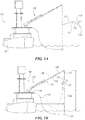
- FIGS 1A-1B illustrate overall views of systems and methods for capturing UAVs in accordance with embodiments of the present technology. Further details of representative capture devices are discussed with reference to Figures 2-10D .
- a representative UAV 110 can be captured by an aircraft handling system 100 positioned on a support platform 101.
- the support platform 101 can include a boat, ship, or other water vessel 102.
- the support platform 101 can include other structures, for example, a building, a truck or other land vehicle, or an airborne vehicle, such as a balloon, helicopter, or other multirotor vehicle, or the aircraft handling system can be placed directly on the ground.
- the aircraft handling system 100 can be configured solely to retrieve the UAV 110 or, in particular embodiments, it can be configured to both launch and retrieve the UAV 110.
- the UAV 110 can include a fuselage 111 and wings 113 (or a blended wing/fuselage), and is propelled by a propulsion system 112 (e.g., a piston-driven propeller).
- the aircraft handling system 100 can include a recovery system 130 integrated with a launch system 170.
- the recovery system 130 can include an extendable boom 131 having a plurality of segments 132.
- the boom 131 can be mounted on a rotatable base 136 or turret for ease of positioning.
- the segments 132 are initially stowed in a nested or telescoping arrangement and are then deployed to extend outwardly as shown in Figure 1B .
- the extendable boom 131 can have other arrangements, such as a scissors arrangement, a parallel linkage arrangement or a knuckle boom arrangement.
- the extendable boom 131 can include a recovery line or capture line 133 extended by gravity or other forces.
- the recovery line 133 can include 0.25 inch diameter polyester rope, and in other embodiments, the recovery line 133 can include other materials and/or can have other dimensions (e.g., a diameter of 0.3125 inch).
- a spring or weight 134 at the end of the recovery line 133 can provide tension in the recovery line 133.
- the aircraft handling system 100 can also include a retrieval line 135 connected to the weight 134 to aid in retrieving and controlling the motion of the weight 134 after the aircraft recovery operation has been completed.
- a different recovery line 133a (shown in dashed lines) can be suspended from one portion of the boom 131 and can attach to another point on the boom 131, in lieu of the recovery line 133 and the weight 134.
- the end of the extendable boom 131 can be positioned at an elevation A above the local surface (e.g., the water shown in Figure 1 B) , and a distance D away from the nearest vertical structure projecting from the local surface.
- the elevation A can be about 15 meters and the distance D can be about 10 meters.
- a and D can have other values, depending upon the particular installation, the size of the UAV 110, and/or other factors.
- the elevation A can be about 17 meters when the boom 131 is extended, and about 4 meters when the boom 131 is retracted.
- the distance D can be about 8 meters when the boom 131 is extended, and about 4 meters when the boom 131 is retracted.
- the boom 131 can be configured to carry both a vertical load and a lateral load via the recovery line.
- the boom 131 can be configured to capture an UAV 110 having a weight of about 30 pounds, and can be configured to withstand a side load of about 400 pounds, corresponding to the force of the impact between the UAV 110 and the recovery line 133 with appropriate factors of safety.
- the UAV 110 is captured when it flies into the recovery line 133. Once captured, the UAV 110 is suspended from the recovery line, e.g., by one of the wings 113. Further details of apparatuses and methods for capturing the UAV 110 are described below with reference to Figures 2-10D .
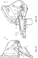
- FIG 2 is a partially schematic, isometric illustration of an outboard portion of the wing 113 of the UAV 110 shown in Figure 1B .
- the wing 113 can include a winglet 116 in the illustrated embodiment and may have no winglets in other embodiments.
- the wing 113 includes a leading edge 114 (which can, but need not be swept), an outboard edge 115, and a line capture device 140 positioned at or near the outboard edge 115.
- each wing 113 can include a plurality of line capture devices 140 located along the span of the wing 113, or a single line capture device located away from the outboard edge 115.
- the line capture device 140 can have a cleat-type configuration.
- the line capture device 140 can include a line capture device body 141 with a bracket or flange 144 that is attached to the wing 113, e.g., with bolts 145.
- the line capture device 140 engages the recovery line 133 to releasably and securely attach the UAV 110 to the recovery line 133.
- the device 140 can include a line slot 143 positioned in the body 141, and retainer 142 movably attached to the body 141.
- the recovery line 133 strikes the wing leading edge 114 and causes the UAV 110 to yaw toward the recovery line 133, which then slides outboard along the leading edge 114 toward the line capture device 140 (as indicated by arrow B).
- the recovery line 133 then passes into the line slot 143 and is retained in the line slot 143 by the retainer 142, as described in greater detail below.
- the recovery line 133 may strike the line capture device 140 instead of the leading edge 114.
- the body 141 includes a guide portion 146 having a body leading edge 155 that is swept aft so as to deflect the recovery line 133 away from the UAV 110. This can prevent the recovery line 133 from fouling and can reduce the yawing moment imparted to the UAV 110, allowing the UAV 110 to recover from the missed capture and return for another capture attempt.
- the recovery line 133 travels outboard along the wing leading edge 114 toward the line capture device 140. As the recovery line 133 enters the line slot 143, it forces the retainer 142 to move from the closed position shown in Figure 2 to an open position. The recovery line 133 travels within the line slot 143 and a locking device 160 engages the retainer 142 to prevent the retainer 142 from opening, either under the force of the recovery line 133, or otherwise. After the aircraft has been successfully captured, an operator uses a release device 180 to disengage the locking device 160 and remove the UAV 110 from the recovery line 133. Further details of this operation are described below with reference to Figures 3A-7B .
- Figures 3A and 3B are plan and isometric views, respectively, of the capture device 140 shown in Figure 2 .
- the line slot 143 has an open end 150 and a closed end 151.
- the retainer 142 can include a flat portion 147 that extends over the line slot 143 when the retainer 142 is in a first or closed position, as illustrated in Figures 3A and 3B .
- the retainer 142 can pivot relative to the body 141, and can be biased towards the closed position with a retainer spring 148.
- the spring 148 includes a wire that extends downwardly into and through a first aperture 156a, then back upwardly through a second aperture 156b, so as to allow the retainer 142 to pivot about an axis extending upwardly and downwardly through the first aperture 156a, as indicated by arrow E.
- the retainer 142 can include a notch 149 that receives the locking device 160, as described further below.
- the locking device 160 can include a locking element 165 that slides axially within a lock groove 166, as indicated by arrow F.
- the locking element 165 can include a protrusion 164 that is positioned underneath the flat portion 147 of the retainer 142 when the locking device 160 is not engaged (e.g., when the locking device 160 is in an unlocked position).
- the retainer 142 is free rotate freely as indicated by arrow E, while the flat portion 147 rotates over the protrusion 164 below.
- the protrusion 164 pops into the notch 149 when the locking device 160 is engaged, as is described further below with reference to Figures 5A and 5B .
- the locking device 160 can further include a line strike device 161 positioned toward the closed end 151 of the line slot 143.
- the line strike device 161 is positioned to pull the locking element 165 from left to right when the recovery line 133 strikes the line strike device 161.
- the line strike device 161 can include a line strike flat portion 162 that extends over and across the capture slot 143, and can move between an unstruck position and a struck position under the force of the recovery line 133.
- the release device 180 is coupled to the locking device 160, e.g., via the line strike device 161 and/or the locking element 165.
- the release device 180 can include a release device spring 181 that biases the release device 180 toward an engaged position shown in Figures 3A and 3B .
- the release device spring 181 can include a wire that operates generally similarly to the retainer spring 148 described above.
- the release device 180 can have a contoured surface allowing a user to easily engage and move it from left to right (or counter-clockwise), indicated by arrow G, to release the locking device 160, as will be described further below with reference to Figures 7A and 7B .
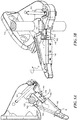
- Figures 4A and 4B are partially schematic plan and isometric views, respectively, of the line capture device 140 shown in Figures 3A and 3B , after the recovery line 133 has entered the line capture slot 143 and forced the retainer 142 to pivot away from the line capture slot 143, as indicated by arrow E.
- the recovery line 133 continues to move along the line capture slot 143 toward the closed end 151.
- the portion of the recovery line 133 within the capture slot 143 can assume an elliptical and/or otherwise non-circular cross-sectional shape due to the confined width of the capture slot 143, as shown in Figure 4A and several subsequent Figures.
- the locking device 160 prevents the retainer 142 from moving away from its closed position. Accordingly, if another portion of the recovery line 133 outside the capture slot 143 loops upwardly and strikes the retainer 142, the retainer 142 will not move from its closed position.
- An advantage of this feature is that it can prevent the retainer 142 from inadvertently being reopened as the recovery line 133 bounces, loops and/or otherwise moves around during the capture operation. Such movement might otherwise not only cause the retainer 142 to open, but also cause the captured portion of the recovery line 133 to move out of capture slot 143 and thus prevent the successful capture of the UAV 110 ( Figures 1A, 1B ).
- the recovery line 133 has now traveled to the closed end 151 of the slot 143 and is fully engaged in the capture slot 143.
- the line strike device 161 has moved clear of the capture slot 143 under the force of the recovery line 133, but the locking device 160 (e.g., the protrusion 164) remains positioned in the notch 149 of the retainer 142 to prevent the retainer 142 from inadvertently opening.
- the UAV is now captured.
- Figures 7A and 7B illustrate a representative operation for removing the UAV from the recovery line 133 by unlocking and disengaging the line capture device 140.
- an operator can slide and/or pivot the release device 180 as indicated by arrow G to pull the locking device 160 out of engagement with the retainer 142.
- the protrusion 164 is pulled away from the notch 149 (as is best seen in Figure 7B ), allowing the retainer 142 to be pivoted to its open position (as is best seen in Figure 7A ). With the retainer 142 in its open position, the user can pull the recovery line 133 out of the slot 143, as indicated by arrow H, and release the UAV.
- the locking device 160 can include at least one unlocked position, and in this embodiment, two unlocked positions: a first unlocked position shown in Figures 3A and 3B (prior to the entry of the recovery line 133 into the line slot 143), and a second unlocked position shown in Figures 7A, 7B (after the recovery line 133 has entered the line slot 143, but before the UAV has been released).
- Figures 8A and 8B schematically illustrate a line capture device 840 having a construction generally similar to that described above with reference to Figures 2-7B , but with a simplified release device 880.
- the release device 880 can include just a release device spring 881 (e.g., a wire spring), which operates as a line strike device, a spring, and the release device itself.
- a corresponding retainer 842 and locking device 860 operate in a manner generally similar to that discussed above with reference to Figures 3A-7B .
- the recovery line 133 strikes a line strike portion 861 to pull a locking element 865 (e.g., having a protrusion 864) from left to right to lock the retainer 842.
- the operator engages an outwardly-facing wire portion 883 of the release device 880 and rotates it as indicated by arrow G to pull the protrusion 864 out of the corresponding notch 849 in a manner generally similar to that discussed above with reference to Figures 7A-7B .
- FIGS 9A and 9B schematically illustrate a line capture device 940 configured in accordance with still another embodiment of the present technology.
- a single element e.g., a unitary wire
- the line capture device 940 can include a retainer 942 that is biased to a closed position via a retainer spring 948 that operates in generally the same manner described above with reference to Figures 3A-7B .
- a wire 976 (e.g., a single wire) includes a line strike portion 961 that receives the impact of the recovery line 133 and pivots as indicated by arrow G.
- the same wire 976 can include a locking portion 960 that is shown in its initial position beneath the retainer 942 in Figures 9A-9B .
- the recovery line 133 strikes the line strike portion 961 and pivots the wire 976 counterclockwise, as indicated by arrow G, the locking portion 960 emerges from underneath the retainer 942 and fits into a corresponding notch 949 to prevent the retainer 942 from moving from the closed position to the open position.
- the wire 976 can still further include a release portion 980 having a curved or otherwise suitable shape that the operator can manipulate (e.g., with the thumb) to move the locking portion 960 away from the retainer 942 and unlock the locking portion in a manner generally similar to that described above.
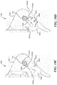
- Figures 10A-10D are partially schematic, plan view illustrations of a line capture device 1040 configured in accordance with still another embodiment of the present technology.
- the line capture device 1040 includes a body 1041 having a line capture slot 1043, and a retainer 1042 pivotably attached to the body 1041 so as to pivot about a pivot axis 1053 that extends inwardly and outwardly out of the plane of Figures 10A-10D .
- the retainer 1042 has multiple lobes 1052, illustrated as a first lobe 1052a, a second lobe 1052b, and a third lobe 1052c.
- the pivotable connection between the body 1041 and the retainer 1042 can include a biasing device 1054 that operates as a torque spring.
- the biasing device 1054 can bias the retainer 1042 to an initial or starting position shown in Figure 10A .
- the line capture device is initially set to the initial or starting position shown in Figure 10A , with the first lobe 1052a positioned on one side of the line capture slot 1043, and the second lobe 1052b positioned in the line capture slot 1043.
- the force pivots the retainer 1042 clockwise about the pivot axis 1053 so as to move the second lobe 1052b out of the line capture slot 1043, allowing the recovery line 133 to move into the line capture slot 1043.
- the second lobe 1052b is in the process of rotating clockwise under the force of the incoming recovery line 133.
- the first lobe 1052a rotates to close off the line capture slot 1043 behind the entering recovery line 133, as is also shown in Figure 10B .
- the retainer 1042 has rotated counterclockwise under the restoring force of the biasing device 1054 to further constrain the motion of the now-captured recovery line 133.
- both the first lobe 1052a and the second lobe 1052b can prevent another portion of the recovery line 133 (e.g., a looping portion) from entering the line capture slot 1043.
- FIG 10D an operator has begun to disengage the capture line 133 from the line capture device 1040 by rotating the retainer 1042 clockwise (as indicated by arrow P), allowing the operator to move the capture line 133 past the second lobe 1052b and toward the entrance of the line capture slot 1043.
- the operator can rotate the retainer 1042 counterclockwise, as indicated by arrow Q, until the retainer 1042 has the position shown in Figure 10A .
- the operator can disengage the capture line 133 by moving it past the first lobe 1052a and out of the line capture slot 1043.
- Devices in accordance with embodiments of the technology described above with reference to Figures 10A-10D can perform functions similar or identical to those described above with reference to Figures 2-9B .
- the second and third lobes 1052b, 1052c can prevent the capture line 133 from exiting the line capture slot 1043, effectively locking the device until the operator unlocks the device (as shown in Figure 10D ).
- the first lobe 1052a can prevent another capture line, or another portion of the capture line 133, from entering and/or opening the line capture slot 1043.
- the line capture devices can include a locking mechanism or device.
- the locking device at least restricts (and typically prevents) the retainer from opening, once the capture device has successfully engaged with a recovery line, unless the operator deliberately unlocks the device.
- An advantage of this arrangement is that it can reduce or eliminate the likelihood for the recovery line to "loop" or otherwise undergo a motion that opens the retainer, which can allow an already-engaged recovery line to escape from the line slot. As a result, the likelihood for a capture maneuver to fail can be significantly reduced.
Landscapes
- Engineering & Computer Science (AREA)
- Aviation & Aerospace Engineering (AREA)
- Mechanical Engineering (AREA)
- Remote Sensing (AREA)
- Transportation (AREA)
- Catching Or Destruction (AREA)
- Load-Engaging Elements For Cranes (AREA)
- Lock And Its Accessories (AREA)
- Control Of Position, Course, Altitude, Or Attitude Of Moving Bodies (AREA)
Abstract
Description
- The present technology is directed generally to locking line capture devices for unmanned aircraft, and associated systems and methods.
- Unmanned aircraft or aerial vehicles (UAVs) provide enhanced and economical access to areas where manned flight operations are unacceptably costly and/or dangerous. For example, UAVs outfitted with remotely controlled cameras can perform a wide variety of surveillance missions, including spotting schools of fish for the fisheries industry, monitoring weather conditions, providing border patrols for national governments, and providing military surveillance before, during and/or after military operations.
- Existing UAV systems suffer from a variety of drawbacks. For example, existing UAVs systems (which can include the aircraft itself along with launch devices, recovery devices, and storage devices) typically require substantial space. Accordingly, these systems can be difficult to install and operate in cramped quarters, such as the deck of a small fishing boat, land vehicle, or other craft. Another drawback with some existing UAVs is that, due to small size and low weight, they can be subjected to higher acceleration and deceleration forces than larger, manned aerial vehicles and can accordingly be prone to damage, particularly when manually handled during recovery and launch operations in hostile environments, such as a heaving ship deck. Yet another drawback with some existing UAV systems is that they may not be suitable for recovering aircraft in tight quarters, without causing damage to either the aircraft or the platform from which the aircraft is launched and/or recovered. Accordingly, there remains a need in the industry for improved methods for operating UAVs in confined environments.
-
-
Figures 1A-1B illustrate an apparatus configured to recover UAVs in accordance with representative embodiments of the present technology. -
Figure 2 is a partially schematic, isometric illustration of a line capture device carried by a UAV in accordance with an embodiment of the present technology. -
Figures 3A and 3B are partially schematic, plan and isometric views, respectively, of the line capture device shown inFigure 2 , with a recovery line positioned to enter a line slot of the device in accordance with an embodiment of the present technology. -
Figures 4A and 4B are partially schematic, plan and isometric views, respectively, of the line capture device shown inFigure 2 , with the recovery line positioned in the line slot, in accordance with an embodiment of the present technology. -
Figures 5A and 5B are partially schematic, plan and isometric views, respectively, of the line capture device shown inFigure 2 , with a locking device in a locked position, in accordance with an embodiment of the present technology. -
Figures 6A and 6B are partially schematic, plan and isometric views, respectively, of the line capture device shown inFigure 2 , with the recovery line fully engaged in the capture slot, in accordance with an embodiment of the present technology. -
Figures 7A and 7B are partially schematic, plan and isometric views, respectively, of the line capture device shown inFigure 2 with the locking device shown in an unlocked position in accordance with an embodiment of the present technology. -
Figures 8A and 8B are partially schematic, plan and isometric views, respectively, of a line capture device having a retainer and locking mechanism configured in accordance with another embodiment of the present technology. -
Figures 9A and 9B are plan and isometric views, respectively, of a capture device having a locking mechanism configured in accordance with yet another embodiment of the present technology. -
Figures 10A-10D illustrate plan views of a line capture device having a retainer with three lobes positioned in a first, second, and third orientation, respectively, in accordance with still another embodiment of the present technology. - The present technology is directed generally to unmanned aerial vehicles (UAVs) having locking capture devices, and associated systems and methods. In particular embodiments, the capture devices are mounted on the wing tips of the UAV and are used to "snag" the UAV on a recovery line, thus eliminating the need for a runway, net, and/or other landing arrangement. A representative capture device includes a slot and a retainer that can prevent the recovery line from disengaging from the slot once the UAV has been captured. A locking device further secures the retainer, and can be released by the operator after the UAV has been captured in preparation for detaching the UAV from the recovery line.
- The invention can involve an unmanned aerial vehicle (UAV) 110
system 100, that may include aline capture body 141 having aline slot 143, theline slot 143 having an open end and a closedend 151; aretainer 142 positioned proximate theline slot 143 and movable between a first position in which theretainer 142 blocks access to theline slot 143 and a second position in which theretainer 142 allows access to theline slot 143;alocking device 160 operably coupled between theline capture body 141 and theretainer 142, and moveable between at least one unlocked position in which thelocking device 160 allows movement of theretainer 142 from the first position to the second position, and a locked position in which thelocking device 160 blocks movement of theretainer 142 from the first position to the second position; and arelease device 180 operably coupled to thelocking device 160 and moveable between a secured position with thelocking device 160 secured in the locked position, and a released position with thelocking device 160 movable between the locked position and the unlocked position. Theretainer 142 may include aflat portion 147 that extends over theline slot 143 when theretainer 142 is in the first position, and wherein the system further comprises aspring 148 coupled between theretainer 142 and theline capture body 141, with thespring 148 biasing theretainer 142 to the first position. Thelocking device 160 may be slideable between the locked and unlocked positions. Thelocking device 160 may include alocking element 165 that is slideable between the locked and unlocked positions; and aline strike device 161 positioned across theline slot 143, and operably coupled to both theline capture body 141 and thelocking element 165, theline strike device 161 being movable between an unstruck position with thelocking device 160 in the unlocked position, and a struck position with thelocking device 160 in the locked position. Theline strike device 161 may include an elongated wire. Theline strike device 161 may include aflat portion 147 positioned across theslot 143. Theretainer 142 may include aflat portion 147 that extends over the slot when theretainer 142 is in the first position, theflat portion 147 including anotch 149, and wherein thelocking device 160 includes aprotrusion 164 that is positioned in thenotch 149 when thelocking device 160 is in the locked position, and is positioned out of thenotch 149 when thelocking device 160 is in the unlocked position. Thelocking device 160 may include a wire having a line strike portion positioned across theline slot 143 to make contact with therecovery line 133, and a locking portion positioned to engage with theretainer 142 when thelocking device 160 is in the locked position. Theretainer 142 may include anotch 149, and wherein the locking portion of thelocking device 160 is positioned in thenotch 149 when thelocking device 160 is in the locked position, and is positioned out of thenotch 149 when thelocking device 160 is in the unlocked position. Thelocking device 160 and therelease device 180 by both be portions of a single unitary wire. Thesystem 100 may also include aUAV 110 having a wing, and wherein theline capture body 141 is attached to thewing 113. - The invention can involve an unmanned aerial vehicle (UAV) 110
system 100, that may include aUAV 110 having awing 113; aline capture body 141 attached to thewing 113 and having aline slot 143, theline slot 143 having an open end and a closedend 151, theline capture body 141 further having alock groove 166; aretainer 142 having aflat portion 147 with anotch 149, theretainer 142 being positioned proximate theline slot 143 and movable between a first position in which theflat portion 147 is positioned over theline slot 143 to block access to theline slot 143 and a second position in which theflat portion 147 is rotated away from the first position to allow access to theline slot 143; alocking device 160 operably coupled between theline capture body 141 and theretainer 142, the locking device160 may include alocking element 165 positioned in thelock groove 166 and slideable between an unlocked position in which thelocking device 160 allows movement of theretainer 142 from the first position to the second position, and a locked position in which thelocking device 160 blocks movement of theretainer 142 from the first position to the second position, thelocking element 165 further including aprotrusion 164 that is positioned in thenotch 149 when thelocking device 160 is in the locked position, and is positioned out of thenotch 149 when thelocking device 160 is in the unlocked position; aline strike device 161 positioned across theline slot 143, and operably coupled to both theline capture body 141 and thelocking element 165, theline strike device 161 being movable between an unstruck position with thelocking element 165 in the unlocked position, and a struck position with thelocking element 165 in the locked position; and arelease device 180 operably coupled to thelocking device 160 and moveable between a secured position with thelocking element 165 secured in the locked position, and a released position with thelocking element 165 movable between the locked position and the unlocked position. Theline strike device 161 may include a wire pivotably coupled between theline capture body 141 and thelocking element 165. Thelocking device 160 and therelease device 180 may both be portions of a single unitary wire. - The invention can involve an unmanned aerial vehicle (UAV) 110
system 100, that may include aline capture body 1041 having aline slot 1043, theline slot 1043 having an open end and a closed end; aretainer 1042 having afirst lobe 1052a, asecond lobe 1052b, and athird lobe 1052c, and being positioned proximate theline slot 1043, theretainer 1042 being movable among three positions: a first position in which the first andthird lobes line slot 1043 and thesecond lobe 1052b is positioned over theline slot 1043; a second position in which thefirst lobe 1052a is positioned over theline slot 1043 and the second andthird lobes line slot 1043; and a third position in which the first andsecond lobes line slot 1043 and thethird lobe 1052c is positioned clear of theline slot 1043; and abiasing device 1054 coupled between theline capture body 1041 and theretainer 1042 to bias theretainer 1042 toward the first position. Theretainer 1042 is pivotable relative to theline capture body 1041 among the first, second and third positions. - The invention can involve a method for capturing an unmanned aerial vehicle (UAV) 110, that may include directing the
UAV 110 toward arecovery line 133; engaging aline capture device 140 carried by theUAV 110 with therecovery line 133 by moving at least one of theUAV 110 and therecovery line 133 relative to the other, causing a portion of therecovery line 133 to enter aline slot 143 of thecapture device 140 and move aretainer 142 of thecapture device 140 from a first position to a second position; after therecovery line 133 has entered theline slot 143, engaging alocking device 160 with theretainer 142 to prevent theretainer 142 from moving from the first position to the second position; and after the UAV has been captured, releasing theUAV 110 from therecovery line 133 by moving alocking device 160 from a secured position, with thelocking device 160 secured in the locked position, to a released position, with thelocking device 160 movable between the locked position and the unlocked position. The portion of therecovery line 133 may be a first portion, and wherein theretainer 142, in the second position, prevents a second portion of therecovery line 133 from entering theline slot 143. Therecovery line 133 may rotate theretainer 142 from the first position to the second position. Engaging thelocking device 160 may include sliding thelocking device 160. - Engaging the
locking device 160 may include moving a portion of thelocking device 160 from a position beneath theretainer 142. Engaging thelocking device 160 may include moving a portion of thelocking device 160 into anotch 149 of theretainer 142. Causing the portion of therecovery line 133 to move theretainer 142 may include causing the portion of therecovery line 133 to strike aline strike device 161 coupled to theretainer 142. The line strike device may include aflat portion 147 positioned across theline slot 143. Theline strike device 161 may include a portion of a wire. - Several details describing structures or processes that are well-known and often associated with UAVs and corresponding systems and subsystems, but that may unnecessarily obscure some significant aspects of the disclosed technology, are not set forth in the following description for purposes of clarity. Moreover, although the following disclosure sets forth several embodiments of different aspects of the technology, some other embodiments can have different configurations and/or different components than those described in this section. Accordingly, the technology may have other embodiments with additional elements and/or without several of the elements described below with reference to
Figures 1A-10D . -
Figures 1A-1B illustrate overall views of systems and methods for capturing UAVs in accordance with embodiments of the present technology. Further details of representative capture devices are discussed with reference toFigures 2-10D . Beginning withFigure 1A , arepresentative UAV 110 can be captured by anaircraft handling system 100 positioned on asupport platform 101. In one embodiment, thesupport platform 101 can include a boat, ship, orother water vessel 102. In other embodiments, thesupport platform 101 can include other structures, for example, a building, a truck or other land vehicle, or an airborne vehicle, such as a balloon, helicopter, or other multirotor vehicle, or the aircraft handling system can be placed directly on the ground. In many of these embodiments, theaircraft handling system 100 can be configured solely to retrieve the UAV 110 or, in particular embodiments, it can be configured to both launch and retrieve the UAV 110. The UAV 110 can include afuselage 111 and wings 113 (or a blended wing/fuselage), and is propelled by a propulsion system 112 (e.g., a piston-driven propeller). - Referring now to
Figure 1B , theaircraft handling system 100 can include arecovery system 130 integrated with alaunch system 170. In one aspect of this embodiment, therecovery system 130 can include anextendable boom 131 having a plurality ofsegments 132. Theboom 131 can be mounted on arotatable base 136 or turret for ease of positioning. Thesegments 132 are initially stowed in a nested or telescoping arrangement and are then deployed to extend outwardly as shown inFigure 1B . In other embodiments, theextendable boom 131 can have other arrangements, such as a scissors arrangement, a parallel linkage arrangement or a knuckle boom arrangement. In any of these embodiments, theextendable boom 131 can include a recovery line orcapture line 133 extended by gravity or other forces. In one embodiment, therecovery line 133 can include 0.25 inch diameter polyester rope, and in other embodiments, therecovery line 133 can include other materials and/or can have other dimensions (e.g., a diameter of 0.3125 inch). In any of these embodiments, a spring orweight 134 at the end of therecovery line 133 can provide tension in therecovery line 133. Theaircraft handling system 100 can also include aretrieval line 135 connected to theweight 134 to aid in retrieving and controlling the motion of theweight 134 after the aircraft recovery operation has been completed. In another embodiment, adifferent recovery line 133a (shown in dashed lines) can be suspended from one portion of theboom 131 and can attach to another point on theboom 131, in lieu of therecovery line 133 and theweight 134. - In one aspect of this embodiment, the end of the
extendable boom 131 can be positioned at an elevation A above the local surface (e.g., the water shown inFigure 1 B) , and a distance D away from the nearest vertical structure projecting from the local surface. In one aspect of this embodiment, the elevation A can be about 15 meters and the distance D can be about 10 meters. In other embodiments, A and D can have other values, depending upon the particular installation, the size of theUAV 110, and/or other factors. For example, in one particular embodiment, the elevation A can be about 17 meters when theboom 131 is extended, and about 4 meters when theboom 131 is retracted. The distance D can be about 8 meters when theboom 131 is extended, and about 4 meters when theboom 131 is retracted. In a further particular aspect of this embodiment, theboom 131 can be configured to carry both a vertical load and a lateral load via the recovery line. For example, in one embodiment, theboom 131 can be configured to capture anUAV 110 having a weight of about 30 pounds, and can be configured to withstand a side load of about 400 pounds, corresponding to the force of the impact between theUAV 110 and therecovery line 133 with appropriate factors of safety. - In any of the foregoing embodiments, the
UAV 110 is captured when it flies into therecovery line 133. Once captured, theUAV 110 is suspended from the recovery line, e.g., by one of thewings 113. Further details of apparatuses and methods for capturing theUAV 110 are described below with reference toFigures 2-10D . -
Figure 2 is a partially schematic, isometric illustration of an outboard portion of thewing 113 of theUAV 110 shown inFigure 1B . Thewing 113 can include awinglet 116 in the illustrated embodiment and may have no winglets in other embodiments. In one aspect of the illustrated embodiment, thewing 113 includes a leading edge 114 (which can, but need not be swept), anoutboard edge 115, and aline capture device 140 positioned at or near theoutboard edge 115. In other embodiments, eachwing 113 can include a plurality ofline capture devices 140 located along the span of thewing 113, or a single line capture device located away from theoutboard edge 115. In any of these embodiments, theline capture device 140 can have a cleat-type configuration. Theline capture device 140 can include a linecapture device body 141 with a bracket orflange 144 that is attached to thewing 113, e.g., withbolts 145. - In operation, the
line capture device 140 engages therecovery line 133 to releasably and securely attach theUAV 110 to therecovery line 133. Accordingly, thedevice 140 can include aline slot 143 positioned in thebody 141, andretainer 142 movably attached to thebody 141. As theUAV 110 flies toward the recovery line 133 (as indicated by arrow C), therecovery line 133 strikes thewing leading edge 114 and causes theUAV 110 to yaw toward therecovery line 133, which then slides outboard along theleading edge 114 toward the line capture device 140 (as indicated by arrow B). Therecovery line 133 then passes into theline slot 143 and is retained in theline slot 143 by theretainer 142, as described in greater detail below. If theUAV 110 is not properly aligned with therecovery line 133 during its approach, therecovery line 133 may strike theline capture device 140 instead of theleading edge 114. In one embodiment, thebody 141 includes aguide portion 146 having abody leading edge 155 that is swept aft so as to deflect therecovery line 133 away from theUAV 110. This can prevent therecovery line 133 from fouling and can reduce the yawing moment imparted to theUAV 110, allowing theUAV 110 to recover from the missed capture and return for another capture attempt. - As described above, the
recovery line 133 travels outboard along thewing leading edge 114 toward theline capture device 140. As therecovery line 133 enters theline slot 143, it forces theretainer 142 to move from the closed position shown inFigure 2 to an open position. Therecovery line 133 travels within theline slot 143 and alocking device 160 engages theretainer 142 to prevent theretainer 142 from opening, either under the force of therecovery line 133, or otherwise. After the aircraft has been successfully captured, an operator uses arelease device 180 to disengage thelocking device 160 and remove theUAV 110 from therecovery line 133. Further details of this operation are described below with reference toFigures 3A-7B . -
Figures 3A and 3B are plan and isometric views, respectively, of thecapture device 140 shown inFigure 2 . Theline slot 143 has anopen end 150 and aclosed end 151. Theretainer 142 can include aflat portion 147 that extends over theline slot 143 when theretainer 142 is in a first or closed position, as illustrated inFigures 3A and 3B . Theretainer 142 can pivot relative to thebody 141, and can be biased towards the closed position with aretainer spring 148. In a particular embodiment, thespring 148 includes a wire that extends downwardly into and through afirst aperture 156a, then back upwardly through asecond aperture 156b, so as to allow theretainer 142 to pivot about an axis extending upwardly and downwardly through thefirst aperture 156a, as indicated by arrow E. Theretainer 142 can include anotch 149 that receives thelocking device 160, as described further below. - The
locking device 160 can include alocking element 165 that slides axially within alock groove 166, as indicated by arrow F. The lockingelement 165 can include aprotrusion 164 that is positioned underneath theflat portion 147 of theretainer 142 when thelocking device 160 is not engaged (e.g., when thelocking device 160 is in an unlocked position). When thelocking device 160 is not engaged, theretainer 142 is free rotate freely as indicated by arrow E, while theflat portion 147 rotates over theprotrusion 164 below. Theprotrusion 164 pops into thenotch 149 when thelocking device 160 is engaged, as is described further below with reference toFigures 5A and 5B . - The
locking device 160 can further include aline strike device 161 positioned toward theclosed end 151 of theline slot 143. Theline strike device 161 is positioned to pull thelocking element 165 from left to right when therecovery line 133 strikes theline strike device 161. Accordingly, theline strike device 161 can include a line strikeflat portion 162 that extends over and across thecapture slot 143, and can move between an unstruck position and a struck position under the force of therecovery line 133. - The
release device 180 is coupled to thelocking device 160, e.g., via theline strike device 161 and/or thelocking element 165. Therelease device 180 can include arelease device spring 181 that biases therelease device 180 toward an engaged position shown inFigures 3A and 3B . In a particular embodiment, therelease device spring 181 can include a wire that operates generally similarly to theretainer spring 148 described above. Therelease device 180 can have a contoured surface allowing a user to easily engage and move it from left to right (or counter-clockwise), indicated by arrow G, to release thelocking device 160, as will be described further below with reference toFigures 7A and 7B . -
Figures 4A and 4B are partially schematic plan and isometric views, respectively, of theline capture device 140 shown inFigures 3A and 3B , after therecovery line 133 has entered theline capture slot 143 and forced theretainer 142 to pivot away from theline capture slot 143, as indicated by arrow E. Therecovery line 133 continues to move along theline capture slot 143 toward theclosed end 151. The portion of therecovery line 133 within thecapture slot 143 can assume an elliptical and/or otherwise non-circular cross-sectional shape due to the confined width of thecapture slot 143, as shown inFigure 4A and several subsequent Figures. - In
Figures 5A and 5B , therecovery line 133 has struck theline strike device 161, causing thelocking element 165 to slide within itslock groove 166 as indicated by arrow F. As a result of this movement, theprotrusion 164 emerges from beneath theretainer 142 and into thenotch 149. Theprotrusion 164 is biased upwardly so as to spring upwardly into thenotch 149 after the retainer 142 (which is biased toward its closed position) rotates back to its closed position, as indicated by arrow E. Accordingly, therecovery line 133 is now positioned toward the closed end 151 (Figure 4B ) of theline slot 143 and theretainer 142 is in its closed position to prevent therecovery line 133 from exiting theline slot 143. In addition, thelocking device 160 prevents theretainer 142 from moving away from its closed position. Accordingly, if another portion of therecovery line 133 outside thecapture slot 143 loops upwardly and strikes theretainer 142, theretainer 142 will not move from its closed position. An advantage of this feature is that it can prevent theretainer 142 from inadvertently being reopened as therecovery line 133 bounces, loops and/or otherwise moves around during the capture operation. Such movement might otherwise not only cause theretainer 142 to open, but also cause the captured portion of therecovery line 133 to move out ofcapture slot 143 and thus prevent the successful capture of the UAV 110 (Figures 1A, 1B ). - As shown in
Figures 6A and 6B , therecovery line 133 has now traveled to theclosed end 151 of theslot 143 and is fully engaged in thecapture slot 143. Theline strike device 161 has moved clear of thecapture slot 143 under the force of therecovery line 133, but the locking device 160 (e.g., the protrusion 164) remains positioned in thenotch 149 of theretainer 142 to prevent theretainer 142 from inadvertently opening. The UAV is now captured. -
Figures 7A and 7B illustrate a representative operation for removing the UAV from therecovery line 133 by unlocking and disengaging theline capture device 140. In particular, an operator can slide and/or pivot therelease device 180 as indicated by arrow G to pull thelocking device 160 out of engagement with theretainer 142. In particular, theprotrusion 164 is pulled away from the notch 149 (as is best seen inFigure 7B ), allowing theretainer 142 to be pivoted to its open position (as is best seen inFigure 7A ). With theretainer 142 in its open position, the user can pull therecovery line 133 out of theslot 143, as indicated by arrow H, and release the UAV. Accordingly, thelocking device 160 can include at least one unlocked position, and in this embodiment, two unlocked positions: a first unlocked position shown inFigures 3A and 3B (prior to the entry of therecovery line 133 into the line slot 143), and a second unlocked position shown inFigures 7A, 7B (after therecovery line 133 has entered theline slot 143, but before the UAV has been released). -
Figures 8A and 8B schematically illustrate aline capture device 840 having a construction generally similar to that described above with reference toFigures 2-7B , but with asimplified release device 880. For example, therelease device 880 can include just a release device spring 881 (e.g., a wire spring), which operates as a line strike device, a spring, and the release device itself. Acorresponding retainer 842 and lockingdevice 860 operate in a manner generally similar to that discussed above with reference toFigures 3A-7B . In operation, therecovery line 133 strikes aline strike portion 861 to pull a locking element 865 (e.g., having a protrusion 864) from left to right to lock theretainer 842. To unlock thecapture device 840, the operator engages an outwardly-facingwire portion 883 of therelease device 880 and rotates it as indicated by arrow G to pull theprotrusion 864 out of thecorresponding notch 849 in a manner generally similar to that discussed above with reference toFigures 7A-7B . -
Figures 9A and 9B schematically illustrate aline capture device 940 configured in accordance with still another embodiment of the present technology. In this embodiment, a single element (e.g., a unitary wire) can include, and can perform the functions of, the line strike device, locking device, and release device described above. In particular, theline capture device 940 can include aretainer 942 that is biased to a closed position via aretainer spring 948 that operates in generally the same manner described above with reference toFigures 3A-7B . A wire 976 (e.g., a single wire) includes aline strike portion 961 that receives the impact of therecovery line 133 and pivots as indicated by arrow G. Thesame wire 976 can include a lockingportion 960 that is shown in its initial position beneath theretainer 942 inFigures 9A-9B . When therecovery line 133 strikes theline strike portion 961 and pivots thewire 976 counterclockwise, as indicated by arrow G, the lockingportion 960 emerges from underneath theretainer 942 and fits into acorresponding notch 949 to prevent theretainer 942 from moving from the closed position to the open position. Thewire 976 can still further include arelease portion 980 having a curved or otherwise suitable shape that the operator can manipulate (e.g., with the thumb) to move the lockingportion 960 away from theretainer 942 and unlock the locking portion in a manner generally similar to that described above. -
Figures 10A-10D are partially schematic, plan view illustrations of aline capture device 1040 configured in accordance with still another embodiment of the present technology. In one aspect of this embodiment, theline capture device 1040 includes abody 1041 having aline capture slot 1043, and aretainer 1042 pivotably attached to thebody 1041 so as to pivot about apivot axis 1053 that extends inwardly and outwardly out of the plane ofFigures 10A-10D . Theretainer 1042 has multiple lobes 1052, illustrated as afirst lobe 1052a, asecond lobe 1052b, and athird lobe 1052c. The pivotable connection between thebody 1041 and theretainer 1042 can include abiasing device 1054 that operates as a torque spring. Thebiasing device 1054 can bias theretainer 1042 to an initial or starting position shown inFigure 10A . - In operation, the line capture device is initially set to the initial or starting position shown in
Figure 10A , with thefirst lobe 1052a positioned on one side of theline capture slot 1043, and thesecond lobe 1052b positioned in theline capture slot 1043. When therecovery line 133 strikes thesecond lobe 1052b as it enters the slot, the force pivots theretainer 1042 clockwise about thepivot axis 1053 so as to move thesecond lobe 1052b out of theline capture slot 1043, allowing therecovery line 133 to move into theline capture slot 1043. InFigure 10B , thesecond lobe 1052b is in the process of rotating clockwise under the force of theincoming recovery line 133. Thefirst lobe 1052a rotates to close off theline capture slot 1043 behind the enteringrecovery line 133, as is also shown inFigure 10B . InFigure 10C , theretainer 1042 has rotated counterclockwise under the restoring force of thebiasing device 1054 to further constrain the motion of the now-capturedrecovery line 133. In this instance, both thefirst lobe 1052a and thesecond lobe 1052b can prevent another portion of the recovery line 133 (e.g., a looping portion) from entering theline capture slot 1043. InFigure 10D , an operator has begun to disengage thecapture line 133 from theline capture device 1040 by rotating theretainer 1042 clockwise (as indicated by arrow P), allowing the operator to move thecapture line 133 past thesecond lobe 1052b and toward the entrance of theline capture slot 1043. Once thecapture line 133 is past thesecond lobe 1052b, the operator can rotate theretainer 1042 counterclockwise, as indicated by arrow Q, until theretainer 1042 has the position shown inFigure 10A . At that point, the operator can disengage thecapture line 133 by moving it past thefirst lobe 1052a and out of theline capture slot 1043. - Devices in accordance with embodiments of the technology described above with reference to
Figures 10A-10D can perform functions similar or identical to those described above with reference toFigures 2-9B . For example, when theline capture device 1040 is in the configuration shown inFigure 10C , the second andthird lobes capture line 133 from exiting theline capture slot 1043, effectively locking the device until the operator unlocks the device (as shown inFigure 10D ). In addition, thefirst lobe 1052a can prevent another capture line, or another portion of thecapture line 133, from entering and/or opening theline capture slot 1043. - One feature of at least some of the embodiments described above with reference to
Figures 1A-10D is that the line capture devices can include a locking mechanism or device. The locking device at least restricts (and typically prevents) the retainer from opening, once the capture device has successfully engaged with a recovery line, unless the operator deliberately unlocks the device. An advantage of this arrangement is that it can reduce or eliminate the likelihood for the recovery line to "loop" or otherwise undergo a motion that opens the retainer, which can allow an already-engaged recovery line to escape from the line slot. As a result, the likelihood for a capture maneuver to fail can be significantly reduced. - From the foregoing, it will be appreciated that specific embodiments of the technology have been described herein for purposes of illustration, but that various modifications may be made without deviating from the technology. For example, several of the components described above and illustrated in
Figures 1A-10D can have shapes and arrangements other than those specifically shown and described. In particular embodiments, multiple functions can be performed by individual components, for example, (without limitation) as illustrated inFigures 8A-9B . - Certain aspects of the technology described in the context of particular embodiments may be combined or eliminated in other embodiments. For example, features of the
release device 180 described above with reference toFigures 3A-7B may be added to the device described above with reference toFigures 9A-9B to make operation of the device more comfortable. Elements of the locking devices and/or release devices discussed above with reference toFigures 3A-9B can be applied to the device shown inFigures 10A-10D . Further, while advantages associated with certain embodiments of the disclosed technology have been described in the context of those embodiments, other embodiments may also exhibit such advantages, and not all embodiments need necessarily exhibit such advantages to fall within the scope of the present technology. Accordingly, the present disclosure and associated technology can encompass other embodiments not expressly shown or described herein.
Claims (15)
- An unmanned aerial vehicle (UAV) system (100), comprising:a line capture body (141) having a line slot (143), the line slot (143) having an open end and a closed end (151);a retainer (142) positioned proximate the line slot (143) and movable between a first position in which the retainer (142) blocks access to the line slot (143) and a second position in which the retainer (142) allows access to the line slot (143);a locking device (160) operably coupled between the line capture body (141) and the retainer (142), and moveable between at least one unlocked position in which the locking device (160) allows movement of the retainer (142) from the first position to the second position, and a locked position in which the locking device (160) blocks movement of the retainer (142) from the first position to the second position; anda release device (180) operably coupled to the locking device (160) and moveable between a secured position with the locking device (160) secured in the locked position, and a released position with the locking device (160) movable between the locked position and the unlocked position.
- The system (100) of claim 1 wherein the retainer (142) includes a flat portion (147) that extends over the line slot (143) when the retainer (142) is in the first position, and wherein the system further comprises a spring (148) coupled between the retainer (142) and the line capture body (141), with the spring (148) biasing the retainer (142) to the first position.
- The system (100) of claim 1 or claim 2 wherein the locking device (160) is slideable between the locked and unlocked positions.
- The system (100) of any preceding claim wherein the locking device (160) includes:a locking element (165) that is slideable between the locked and unlocked positions; anda line strike device (161) positioned across the line slot (143), and operably coupled to both the line capture body (141) and the locking element (165), the line strike device (161) being movable between an unstruck position with the locking device (160) in the unlocked position, and a struck position with the locking device (160) in the locked position.
- The system (100) of claim 1 wherein retainer (142) includes a flat portion (147) that extends over the slot when the retainer (142) is in the first position, the flat portion (147) including a notch (149), and wherein the locking device (160) includes a protrusion (164) that is positioned in the notch (149) when the locking device (160) is in the locked position, and is positioned out of the notch (149) when the locking device (160) is in the unlocked position.
- The system (100) of any preceding claim wherein the locking device (160) includes a wire having a line strike portion positioned across the line slot (143) to make contact with the recovery line (133), and a locking portion positioned to engage with the retainer (142) when the locking device (160) is in the locked position.
- The system (100) of any preceding claim wherein the locking device (160) and the release device (180) are both portions of a single unitary wire.
- The system (100) of any preceding claim, further comprising a UAV (110) having a wing, and wherein the line capture body (141) is attached to the wing (113).
- A method for capturing an unmanned aerial vehicle (UAV) (110), comprising:directing the UAV (110) toward a recovery line (133);engaging a line capture device (140) carried by the UAV (110) with the recovery line (133) by moving at least one of the UAV (110) and the recovery line (133) relative to the other, causing a portion of the recovery line (133) to enter a line slot (143) of the capture device (140) and move a retainer (142) of the capture device (140) from a first position to a second position;after the recovery line (133) has entered the line slot (143), engaging a locking device (160) with the retainer (142) to prevent the retainer (142) from moving from the first position to the second position; andafter the UAV has been captured, releasing the UAV (110) from the recovery line (133) by moving a locking device (160) from a secured position, with the locking device (160) secured in the locked position, to a released position, with the locking device (160) movable between the locked position and the unlocked position.
- The method of claim 9 wherein the portion of the recovery line (133) is a first portion, and wherein the retainer (142), in the second position, prevents a second portion of the recovery line (133) from entering the line slot (143).
- The method of claim 9 or claim 10 wherein the recovery line (133) rotates the retainer (142) from the first position to the second position.
- The method of any of claims 9 to 11 wherein engaging the locking device (160) includes sliding the locking device (160).
- The method of any of claims 9 to 12 wherein engaging the locking device (160) includes moving a portion of the locking device (160) from a position beneath the retainer (142).
- The method of any of claims 9 to 13 wherein engaging the locking device (160) includes moving a portion of the locking device (160) into a notch (149) of the retainer (142).
- The method of any of claims 9 to 14 wherein causing the portion of the recovery line (133) to move the retainer (142) includes causing the portion of the recovery line (133) to strike a line strike device (161) coupled to the retainer (142).
Priority Applications (1)
| Application Number | Priority Date | Filing Date | Title |
|---|---|---|---|
| EP19216040.6A EP3653501B1 (en) | 2016-06-27 | 2017-06-26 | Locking line capture devices for unmanned aircraft, and associated systems and methods |
Applications Claiming Priority (1)
| Application Number | Priority Date | Filing Date | Title |
|---|---|---|---|
| US15/194,492 US10407181B2 (en) | 2016-06-27 | 2016-06-27 | Locking line capture devices for unmanned aircraft, and associated systems and methods |
Related Child Applications (2)
| Application Number | Title | Priority Date | Filing Date |
|---|---|---|---|
| EP19216040.6A Division EP3653501B1 (en) | 2016-06-27 | 2017-06-26 | Locking line capture devices for unmanned aircraft, and associated systems and methods |
| EP19216040.6A Division-Into EP3653501B1 (en) | 2016-06-27 | 2017-06-26 | Locking line capture devices for unmanned aircraft, and associated systems and methods |
Publications (2)
| Publication Number | Publication Date |
|---|---|
| EP3263455A1 true EP3263455A1 (en) | 2018-01-03 |
| EP3263455B1 EP3263455B1 (en) | 2020-01-29 |
Family
ID=59227534
Family Applications (2)
| Application Number | Title | Priority Date | Filing Date |
|---|---|---|---|
| EP19216040.6A Active EP3653501B1 (en) | 2016-06-27 | 2017-06-26 | Locking line capture devices for unmanned aircraft, and associated systems and methods |
| EP17177785.7A Active EP3263455B1 (en) | 2016-06-27 | 2017-06-26 | Locking line capture devices for unmanned aircraft, and associated systems and methods |
Family Applications Before (1)
| Application Number | Title | Priority Date | Filing Date |
|---|---|---|---|
| EP19216040.6A Active EP3653501B1 (en) | 2016-06-27 | 2017-06-26 | Locking line capture devices for unmanned aircraft, and associated systems and methods |
Country Status (4)
| Country | Link |
|---|---|
| US (2) | US10407181B2 (en) |
| EP (2) | EP3653501B1 (en) |
| AU (1) | AU2017203040B2 (en) |
| IL (2) | IL252290B (en) |
Cited By (1)
| Publication number | Priority date | Publication date | Assignee | Title |
|---|---|---|---|---|
| EP3705406A1 (en) * | 2019-03-06 | 2020-09-09 | Insitu, Inc. (a Subsidiary Of The Boeing Company) | Unmanned aerial vehicle (uav) recovery |
Families Citing this family (23)
| Publication number | Priority date | Publication date | Assignee | Title |
|---|---|---|---|---|
| JP2012524695A (en) | 2009-04-24 | 2012-10-18 | インサイチュー インコーポレイテッド | System and method for retrieving unmanned aerial vehicles and controlling operation after retrieval |
| US8944373B2 (en) | 2010-09-27 | 2015-02-03 | Insitu, Inc. | Line capture devices for unmanned aircraft, and associated systems and methods |
| US10399674B2 (en) | 2014-07-28 | 2019-09-03 | Insitu, Inc. | Systems and methods countering an unmanned air vehicle |
| US9896222B2 (en) | 2014-11-20 | 2018-02-20 | Insitu, Inc. | Capture devices for unmanned aerial vehicles, including track-borne capture lines, and associated systems and methods |
| US10933997B2 (en) | 2015-10-02 | 2021-03-02 | Insitu, Inc. | Aerial launch and/or recovery for unmanned aircraft, and associated systems and methods |
| US10407181B2 (en) | 2016-06-27 | 2019-09-10 | Insitu, Inc. | Locking line capture devices for unmanned aircraft, and associated systems and methods |
| US10696420B2 (en) | 2016-08-17 | 2020-06-30 | Hood Technology Corporation | Rotorcraft-assisted system and method for launching and retrieving a fixed-wing aircraft into and from free flight |
| US11204612B2 (en) | 2017-01-23 | 2021-12-21 | Hood Technology Corporation | Rotorcraft-assisted system and method for launching and retrieving a fixed-wing aircraft |
| US10988257B2 (en) * | 2017-05-11 | 2021-04-27 | Hood Technology Corporation | Aircraft-retrieval system |
| US11524797B2 (en) | 2017-05-11 | 2022-12-13 | Hood Technology Corporation | Aircraft-retrieval system |
| US10767682B2 (en) | 2017-06-29 | 2020-09-08 | Insitu, Inc. | Frangible fasteners with flexible connectors for unmanned aircraft, and associated systems and methods |
| US11667398B2 (en) | 2017-09-06 | 2023-06-06 | Hood Technology Corporation | Multicopter-assisted systems and methods for launching and retrieving a fixed-wing aircraft into and from free flight |
| US11414187B2 (en) | 2017-09-06 | 2022-08-16 | Hood Technology Corporation | Parasail-assisted systems and methods for launching and retrieving a fixed-wing aircraft into and from free flight |
| US11027844B2 (en) | 2017-09-06 | 2021-06-08 | Hood Technology Corporation | Rotorcraft-assisted system for launching and retrieving a fixed-wing aircraft into and from free flight |
| US11312492B1 (en) | 2017-11-09 | 2022-04-26 | Hood Technology Corporation | Rotorcraft-assisted systems and methods for launching and retrieving a fixed-wing aircraft into and from free flight |
| US11142339B2 (en) | 2018-05-04 | 2021-10-12 | Insitu, Inc. | Launch and/or recovery for unmanned aircraft and/or other payloads, including via parachute-assist, and associated systems and methods |
| US11066185B2 (en) | 2018-05-04 | 2021-07-20 | Insitu, Inc. | Launch and/or recovery for unmanned aircraft and/or other payloads, including via parachute-assist, and associated systems and methods |
| GB2576929A (en) * | 2018-09-07 | 2020-03-11 | Airbus Operations Ltd | A wing tip device |
| US11377207B2 (en) * | 2018-10-02 | 2022-07-05 | Insitu, Inc., (A subsidiary of the Boeing Company) | Methods and apparatus to recover rotorcraft |
| US11235892B2 (en) | 2019-05-22 | 2022-02-01 | Hood Technology Corporation | Aircraft retrieval system and method |
| CN110979712B (en) * | 2019-12-02 | 2021-05-07 | 北京特种机械研究所 | Automatic locking and unlocking mechanism for lifting platform |
| UA125842C2 (en) * | 2021-02-17 | 2022-06-15 | Олександр Володимирович Степура | Device for catching and launching an unmanned aircraft |
| US12134466B2 (en) * | 2021-08-09 | 2024-11-05 | Insitu, Inc. | Unmanned aerial vehicles including wing capture devices and related methods |
Citations (3)
| Publication number | Priority date | Publication date | Assignee | Title |
|---|---|---|---|---|
| US20040232282A1 (en) * | 2003-01-17 | 2004-11-25 | Dennis Brian D. | Methods and apparatuses for capturing and recovering unmanned aircraft, including a cleat for capturing aircraft on a line |
| WO2012047677A2 (en) * | 2010-09-27 | 2012-04-12 | Craig Aram Thomasian | Line capture devices for unmanned aircraft, and associated systems and methods |
| US20160137311A1 (en) * | 2013-03-14 | 2016-05-19 | Aurora Flight Sciences Corporation | Aerial system and vehicle for continuous operation |
Family Cites Families (269)
| Publication number | Priority date | Publication date | Assignee | Title |
|---|---|---|---|---|
| US1624188A (en) | 1927-04-12 | Airplanes eeom and upon suspended | ||
| US2735391A (en) | 1956-02-21 | H buschers | ||
| USRE16613E (en) | 1927-05-03 | Safety hook | ||
| US1317631A (en) | 1919-09-30 | kinser | ||
| USRE25406E (en) | 1963-06-25 | Aircraft arresting system | ||
| US965881A (en) | 1909-12-03 | 1910-08-02 | George Otis Draper | Landing and starting apparatus for aeroplanes. |
| US968339A (en) | 1910-02-28 | 1910-08-23 | Gerald Geraldson | Aeroplane launcher and lander. |
| US975953A (en) | 1910-03-05 | 1910-11-15 | Iskander Hourwich | Aerial projecting apparatus. |
| US1164967A (en) | 1913-10-01 | 1915-12-21 | James M Thorp | Aeroplane alighting and launching apparatus. |
| US1144505A (en) | 1914-02-18 | 1915-06-29 | Frank Steffan | Aerial landing and launching appliance. |
| US1428163A (en) | 1917-06-23 | 1922-09-05 | James B Harriss | Launching and landing of aeroplanes |
| US1383595A (en) | 1920-02-25 | 1921-07-05 | Johnny S Black | Airplane landing and launching mechanism |
| US1384036A (en) | 1920-12-27 | 1921-07-12 | Anderson Gustaf | Device for launching aeroplanes from ships |
| US1716670A (en) | 1922-06-27 | 1929-06-11 | Lawrence Sperry Aircraft Compa | Device for launching and landing aeroplanes from and upon suspended positions |
| US1499472A (en) | 1922-07-14 | 1924-07-01 | Hazen C Pratt | Airplane-landing mechanism |
| US1738261A (en) | 1922-07-24 | 1929-12-03 | Willis B Perkins | Aeroplane-handling structure |
| US1816976A (en) | 1922-08-03 | 1931-08-04 | Eclipse Machine Co | Engine starting device for aeroplanes |
| US1532736A (en) | 1923-02-26 | 1925-04-07 | Flannery Bolt Co | Stay bolt for boilers |
| US1530010A (en) | 1924-10-01 | 1925-03-17 | Neilson Albert Howard | Safety hook |
| US1556348A (en) | 1925-02-14 | 1925-10-06 | Curtiss Aeroplane & Motor Co I | Aeroplane landing gear |
| US1869506A (en) | 1925-10-23 | 1932-08-02 | Holden C Richardson | Method of and apparatus for mooring an airplane while in flight to another aircraft |
| US1634964A (en) | 1925-12-29 | 1927-07-05 | Joseph A Steinmetz | Mooring dirigible aircraft |
| US1731091A (en) | 1926-08-05 | 1929-10-08 | Belleville Harry Clayton | Aircraft landing |
| US1749769A (en) | 1927-03-31 | 1930-03-11 | Fairchild Airplane Mfg Corp | Airplane-wing connection |
| US1712164A (en) | 1927-04-01 | 1929-05-07 | Peppin Joseph | Antiaircraft screen |
| US1686298A (en) | 1927-09-10 | 1928-10-02 | George E Ginter | Air or seaplane station |
| US1748663A (en) | 1927-09-20 | 1930-02-25 | Charles B Scoville Jr | Method and means for landing and launching aircraft and aircraft freight |
| US1680473A (en) | 1927-11-23 | 1928-08-14 | Parker Orin | Aeroplane landing and launching device |
| US1756747A (en) | 1928-06-12 | 1930-04-29 | Holland Lionel | Aeroplane-landing means |
| US1737483A (en) | 1928-09-18 | 1929-11-26 | Nicholas J Verret | Take-off and landing apparatus for aeroplanes |
| US1777167A (en) | 1928-11-09 | 1930-09-30 | Forbes William Archib Davidson | Apparatus for launching aircraft |
| US1825578A (en) | 1930-01-02 | 1931-09-29 | Cernuda Antonio | Airplane |
| US1836010A (en) | 1930-05-02 | 1931-12-15 | Constant A Audrain | Airplane landing and launching mechanism |
| US1842432A (en) | 1930-08-02 | 1932-01-26 | Samuel A Stanton | Landing and take-off apparatus for airplanes |
| US1925212A (en) | 1930-09-26 | 1933-09-05 | Arthur A Johnson | Means for facilitating the takingoff and landing of aircraft and refueling the same |
| US1940030A (en) | 1931-02-02 | 1933-12-19 | Arthur A Johnson | Means for facilitating the takingoff and landing of aircraft and refueling the same |
| US1912723A (en) | 1931-03-23 | 1933-06-06 | Willis B Perkins Jr | Airplane landing and launching appliance |
| US1892357A (en) | 1931-04-27 | 1932-12-27 | Edward E Moe | Airplane catapult |
| US1960264A (en) | 1931-10-11 | 1934-05-29 | Heinkel Ernst | Catapult for launching aeroplanes |
| US1909445A (en) | 1931-11-23 | 1933-05-16 | Hazel B Tidland | Parachute |
| US2211089A (en) | 1938-03-29 | 1940-08-13 | Curtiss Wright Corp | Wing and fuselage construction |
| FR854371A (en) | 1938-12-30 | 1940-04-11 | Schneider & Cie | Improvements to catapulting devices |
| US2515205A (en) | 1938-12-30 | 1950-07-18 | Fleux Jean | Catapult device for launching aerial machines |
| US2286381A (en) | 1939-03-14 | 1942-06-16 | Rubissow George Alexis | Method and device for forced takeoff and forced landing of airplanes and airships |
| US2296988A (en) | 1940-08-31 | 1942-09-29 | Waldemar A Endter | Hook type rotary latch |
| US2401853A (en) | 1941-06-23 | 1946-06-11 | Lockheed Aircraft Corp | Aerial torpedo |
| US2365827A (en) | 1941-08-05 | 1944-12-26 | Wingfoot Corp | Rigid airship |
| US2333559A (en) | 1941-08-15 | 1943-11-02 | Daniel W Grady | Airplane anchorage means |
| US2365778A (en) | 1941-09-16 | 1944-12-26 | Martin C Schwab | Mobile device for repelling the attack of enemy aircraft |
| US2342773A (en) | 1942-03-28 | 1944-02-29 | Samuel K Wellman | Landing platform for airplanes |
| US2390754A (en) | 1942-06-10 | 1945-12-11 | Diana Guest | Apparatus for handling airplanes |
| US2347561A (en) | 1942-07-02 | 1944-04-25 | Burton Rodgers Inc | Silhouette model |
| US2360220A (en) | 1943-01-16 | 1944-10-10 | Paul R Goldman | Knockdown decoy airplane and package |
| US2364527A (en) | 1943-04-13 | 1944-12-05 | Carroll M Haygood | Aircraft catching apparatus |
| US2436240A (en) | 1943-10-21 | 1948-02-17 | Anthony P Wiertz | Airplane landing gear |
| US2447945A (en) | 1944-05-05 | 1948-08-24 | Saunders Roe Ltd | Mooring gear for flying boats |
| US2380702A (en) | 1944-06-12 | 1945-07-31 | Meric C Persons | Airplane mooring appliance |
| US2435197A (en) | 1944-10-04 | 1948-02-03 | James H Brodie | Landing and launching apparatus for aircraft |
| US2465936A (en) | 1945-04-26 | 1949-03-29 | All American Airways Inc | Emergency arresting device for moving objects |
| US2526348A (en) | 1945-11-16 | 1950-10-17 | Saunders Roe Ltd | Pickup hook for flying boats |
| US2448209A (en) | 1946-01-23 | 1948-08-31 | Ail American Aviat Inc | Arresting unit for aircraft landing system |
| US2488051A (en) | 1948-01-15 | 1949-11-15 | James H Brodie | Aircraft landing apparatus |
| US2488050A (en) | 1948-01-15 | 1949-11-15 | James H Brodie | Aircraft landing system |
| US2814453A (en) | 1952-03-14 | 1957-11-26 | Glenn L Martin Co | Air base |
| US2671938A (en) | 1952-04-10 | 1954-03-16 | Roberts Malcolm | Self-locking hook |
| US2669403A (en) | 1952-07-21 | 1954-02-16 | Doris A Mckay | Glider carrying and releasing device for kites |
| US2787185A (en) | 1953-06-29 | 1957-04-02 | Boeing Co | Expansion fastener with sealing liner |
| US2843342A (en) | 1955-09-23 | 1958-07-15 | Task Corp | Mobile hydraulic catapulting apparatus |
| US2908240A (en) | 1956-02-07 | 1959-10-13 | Martin Co | Seaplane beaching apparatus |
| US2844340A (en) | 1956-10-16 | 1958-07-22 | All American Eng Co | Weight actuated arresting cable control means for aircraft |
| US2919871A (en) | 1956-11-15 | 1960-01-05 | All American Eng Co | Aircraft runway barriers |
| US2937827A (en) | 1957-01-28 | 1960-05-24 | Ralph E Duce | Counter-rotating propellers and dual engine safety system |
| US2933183A (en) | 1957-03-04 | 1960-04-19 | Vendo Co | Support structure for a missile or the like |
| US2954946A (en) | 1957-06-28 | 1960-10-04 | Edgar A O'neil | Apparatus for assisting the landing of aircraft |
| US3069118A (en) | 1959-05-28 | 1962-12-18 | Aerazur Constr Aeronaut | Means for arresting or stopping a landing aircraft such as compound net barriers |
| US3163380A (en) | 1961-06-02 | 1964-12-29 | James H Brodie | Aircraft launching apparatus |
| US3268090A (en) | 1965-08-23 | 1966-08-23 | Albert R Wirkkala | Articulated log skidder having a telescopic boom for throwing out the inhaul cable |
| DE1481982A1 (en) | 1965-12-01 | 1969-07-17 | Borgs Fabriks Ab | Aircraft barrier |
| GB1164371A (en) | 1966-03-31 | 1969-09-17 | Vsi Corp | Improvements in Blind Fasteners. |
| GB1117856A (en) | 1966-04-15 | 1968-06-26 | Karl Ove Torgny Walander | Arresting device for aircraft |
| US3484061A (en) | 1967-12-13 | 1969-12-16 | Bliss Co | Plural pendant vehicle arresting system |
| US3512447A (en) | 1968-09-09 | 1970-05-19 | Rudolph Marion Vaughn | Frangible nut fastener |
| GB1301097A (en) | 1969-03-28 | 1972-12-29 | Avdel Ltd | Blind fastener |
| US3939988A (en) | 1969-04-09 | 1976-02-24 | General Crane Industries Limited | Tower crane |
| US3516626A (en) | 1969-06-06 | 1970-06-23 | John S Strance | Aircraft launching system |
| US3589651A (en) | 1969-06-09 | 1971-06-29 | Gulf & Western Ind Prod Co | Aircraft arresting device |
| US3672214A (en) | 1969-10-09 | 1972-06-27 | Otis Elevator Co | Rope tension gauge for elevator system |
| SE347484B (en) | 1970-08-28 | 1972-08-07 | Borgs Fabriks Ab | |
| US3708200A (en) | 1970-12-17 | 1973-01-02 | D Richards | Combination house trailer and airplane hangar |
| US3684219A (en) | 1970-12-18 | 1972-08-15 | Robert W King | Glider launcher for kites |
| US3771484A (en) | 1972-04-14 | 1973-11-13 | Us Navy | Inflatable floating island |
| DE2330626A1 (en) | 1972-08-31 | 1974-03-07 | Industrial Acoustics Co | FASTENER WITH SECURITY |
| US4037807A (en) | 1972-09-01 | 1977-07-26 | Short Brothers And Harland Limited | Flight vehicle |
| GB1445835A (en) | 1972-10-04 | 1976-08-11 | Leckie R M P | Toy flying machines |
| US3827660A (en) | 1972-12-05 | 1974-08-06 | All American Ind | Aircraft arresting apparatus |
| GB1471583A (en) | 1974-04-03 | 1977-04-27 | British Aircraft Corp Ltd | Aircraft recovery means and method |
| US4079901A (en) | 1976-04-07 | 1978-03-21 | All American Industries, Inc. | Launching apparatus for flying device |
| US4067139A (en) | 1976-07-16 | 1978-01-10 | L. M. Cox Manufacturing Co., Inc. | Electric powered flying model airplane |
| FR2360467A1 (en) | 1976-08-05 | 1978-03-03 | Aerazur Constr Aeronaut | AIRCRAFT STOP NET |
| US4147317A (en) | 1977-06-23 | 1979-04-03 | All American Industries, Inc. | Mobile RPV landing deck |
| US4149840A (en) | 1977-11-08 | 1979-04-17 | Tippmann Eugene R | Apparatus for producing rigid foam plastic insulating panels |
| US4296898A (en) | 1977-12-23 | 1981-10-27 | Watson Ronald S | Anchor device for propeller rotator |
| USD256816S (en) | 1978-05-26 | 1980-09-09 | Cpg Products Corp. | Toy glider |
| US4236686A (en) | 1978-09-07 | 1980-12-02 | Grumman Aerospace Corporation | Ship compatible launch, retrieval and handling system for (VTOL) aircraft |
| DE2852220C2 (en) | 1978-12-02 | 1983-01-13 | Messerschmitt-Bölkow-Blohm GmbH, 8000 München | Horizontal landing arrangement for missiles |
| US4238093A (en) | 1978-12-21 | 1980-12-09 | The United States Of America As Represented By The Secretary Of The Navy | Aircraft launcher |
| US4279195A (en) | 1978-12-22 | 1981-07-21 | Fairchild Industries, Inc. | Collapsible launching system |
| DE2904749C2 (en) | 1979-02-08 | 1984-01-05 | Messerschmitt-Bölkow-Blohm GmbH, 8000 München | Missile in the manner of a drone |
| US4267987A (en) | 1979-03-29 | 1981-05-19 | Mcdonnell William R | Helicopter airborne load systems and composite aircraft configurations |
| DE2935044A1 (en) | 1979-08-30 | 1981-03-19 | Vereinigte Flugtechnische Werke Gmbh, 2800 Bremen | UNMANNED MISSILE TO BE LAUNCHED FROM A CONTAINER |
| US4311290A (en) | 1979-11-01 | 1982-01-19 | The United States Of America As Represented By The Secretary Of The Navy | Arrestment system |
| GB2080216A (en) | 1979-11-21 | 1982-02-03 | Elliott Brothers London Ltd | Apparatus for use in the recovery of a flying object |
| US4372016A (en) | 1980-07-03 | 1983-02-08 | Gulf & Western Manufacturing Company | Hardware snap and method of producing same |
| GB2093414A (en) | 1981-02-24 | 1982-09-02 | British Aerospace | Apparatus for the collection and retardation of a moving body |
| AU550608B2 (en) | 1981-06-04 | 1986-03-27 | British Aerospace Public Limited Company | Retrieving and launching vtol planes by crane |
| US4730793A (en) | 1981-08-12 | 1988-03-15 | E-Systems, Inc. | Ordnance delivery system and method including remotely piloted or programmable aircraft with yaw-to-turn guidance system |
| DE3133339A1 (en) | 1981-08-22 | 1983-03-10 | Vereinigte Flugtechnische Werke Gmbh, 2800 Bremen | "UNMANNED MISSILE TO START FROM A CONTAINER" |
| FR2521520A1 (en) | 1982-02-15 | 1983-08-19 | Daude Martine | MARGINAL FINS WITH VARIABLE ANGLES OF ATTACK |
| US4678143A (en) | 1982-12-17 | 1987-07-07 | Frazer-Nash Ltd. | Launcher for remotely piloted aircraft |
| FR2538342B1 (en) | 1982-12-23 | 1986-05-16 | Messerschmitt Boelkow Blohm | DEVICE FOR RECOVERING FLYING BODIES WITHOUT EQUIPMENT |
| US4566658A (en) | 1983-08-01 | 1986-01-28 | The United States Of America As Represented By The Secretary Of The Navy | Aircraft barricade |
| GB2150895A (en) | 1983-11-07 | 1985-07-10 | Gq Defence Equip Ltd | Load deployment device |
| US4809933A (en) | 1984-02-21 | 1989-03-07 | Wickes Manufacturing Company | Portable aircraft arresting apparatus |
| US4653706A (en) | 1985-07-29 | 1987-03-31 | Youssef Ragiab | Emergency aircaft landing device |
| IL76726A (en) | 1985-10-16 | 1991-01-31 | Meir Yoffe | Method for point-landing of fixed-wing aircraft by means of cable reel-in |
| US4753400A (en) | 1987-02-13 | 1988-06-28 | Pioneer Systems, Incorporated | Shipboard air vehicle retrieval apparatus |
| US5039034A (en) | 1987-06-01 | 1991-08-13 | Indal Technologies Inc. | Apparatus for capturing, securing and traversing remotely piloted vehicles and methods therefor |
| US4790497A (en) | 1987-06-05 | 1988-12-13 | Meir Yoffe | Point-landing method for non vertical take off and landing flying objects |
| US5007875A (en) | 1987-10-02 | 1991-04-16 | Madhava Dasa | Multiple configuration model aircraft |
| CH676453A5 (en) | 1987-12-10 | 1991-01-31 | Eidgenoess Flugzeugwerk Emmen | |
| GB8814178D0 (en) | 1988-06-15 | 1988-11-16 | Marconi Gec Ltd | Aircraft recovery systems |
| US4991739A (en) | 1988-08-10 | 1991-02-12 | Coin Acceptors, Inc. | Vending machine |
| US4842222A (en) | 1988-09-19 | 1989-06-27 | Baird Eric A | Kite load-releasing device |
| CN1032645A (en) | 1988-10-18 | 1989-05-03 | 黄泽荣 | Stol device for ultralight aircraft |
| US5687930A (en) | 1989-02-02 | 1997-11-18 | Indal Technologies Inc. | System and components useful in landing airborne craft |
| US4979701A (en) | 1989-03-01 | 1990-12-25 | Patron Inc. | Aircraft arresting elemental net with multiple independent bottom horizontal straps |
| DE3910621A1 (en) | 1989-04-01 | 1990-10-04 | Messerschmitt Boelkow Blohm | DEVICE FOR RECOVERING UNMANNED REUSABLE AIRCRAFT |
| GB8910108D0 (en) | 1989-05-03 | 1989-09-20 | Marconi Gec Ltd | Aircraft capture systems |
| FR2648199B1 (en) | 1989-06-09 | 1991-09-27 | Aerospatiale | TEMPORARY LINK DEVICE, PARTICULARLY FOR ARTIFICIAL SATELLITE APPENDIX, AND METHOD FOR RELEASING SUCH A LINK |
| US5042750A (en) | 1989-11-16 | 1991-08-27 | Datron, Inc. | Aircraft arresting system |
| FR2664233A1 (en) | 1990-07-06 | 1992-01-10 | Carrot Louis | SAFETY DEVICE FOR SURVIVAL OF STAFF ON BOARD AIRCRAFT. |
| US5119935A (en) | 1991-01-29 | 1992-06-09 | Grumman Aerospace Corporation | VTOL aircraft convertible shipping container and method of use |
| IL101069A (en) | 1991-02-25 | 1996-09-12 | Valsan Partners Purchase N Y | System for increasing airplane fuel mileage and airplane wing modification kit |
| US5145129A (en) | 1991-06-06 | 1992-09-08 | Grumman Aerospace Corporation | Unmanned boom/canard propeller v/stol aircraft |
| IT1251567B (en) * | 1991-09-10 | 1995-05-17 | Riva Calzoni Spa | EQUIPMENT FOR TAKING, LOCKING AND HANDLING UNDERWATER AND SIMILAR VEHICLES. |
| US5176339A (en) | 1991-09-30 | 1993-01-05 | Lord Corporation | Resilient pivot type aircraft mounting |
| DE4301671A1 (en) | 1992-01-22 | 1993-07-29 | Nord Systemtechnik | Recovery system for drone etc. - has catch line held in frame to lock into hook held above drone, with retarding mounting for line. |
| AU2232192A (en) | 1992-02-17 | 1993-09-03 | Hashimoto, Megumi | Device for landing airship or the like |
| US5222694A (en) | 1992-08-03 | 1993-06-29 | Atr International, Inc. | Aircraft interior panel noise dampening support brackets |
| CA2076151C (en) | 1992-08-14 | 1997-11-11 | John Brooke | System for handling a remotely operated vessel |
| US5253605A (en) | 1992-12-21 | 1993-10-19 | Applied Remote Technology, Inc. | Method and apparatus for deploying and recovering water borne vehicles |
| US5390550A (en) | 1993-05-26 | 1995-02-21 | Miller; George E. | Apparatus for measuring tension in stretched cables |
| DE4409424C1 (en) | 1994-03-18 | 1995-08-10 | Daimler Benz Aerospace Ag | Catchment device for flying objects |
| JPH07304498A (en) | 1994-05-13 | 1995-11-21 | Nec Corp | Recovering method and device for unmanned aircraft |
| US5603592A (en) | 1994-10-03 | 1997-02-18 | Huck International, Inc. | High strength blind bolt with uniform high clamp over an extended grip range |
| EP0742366B1 (en) | 1995-05-12 | 1998-09-30 | Yamaha Hatsudoki Kabushiki Kaisha | Internal combustion engine |
| DE19602703A1 (en) | 1995-08-24 | 1997-02-27 | Udo Wagener | Twin=port, two=stroke, high=speed engine |
| US5816761A (en) | 1996-01-11 | 1998-10-06 | The Boeing Company | Lightweight structural blind fastener |
| US5655944A (en) | 1996-03-01 | 1997-08-12 | Fusselman; Robert M. | Packaging apparatus and aerial device formed from sheet material |
| US5762456A (en) | 1996-05-17 | 1998-06-09 | Asar Group, Inc. | Self tapping blind setting bolt rivet assembly |
| US5913479A (en) | 1996-09-18 | 1999-06-22 | Westwood, Iii; Samuel M. | Snap hook with pivotal gate |
| US6161797A (en) | 1996-11-25 | 2000-12-19 | Dugan Air Technologies, Inc. | Method and apparatus for reducing airplane noise |
| US5906336A (en) | 1997-11-14 | 1999-05-25 | Eckstein; Donald | Method and apparatus for temporarily interconnecting an unmanned aerial vehicle |
| AU4690899A (en) | 1998-06-18 | 2000-01-05 | Kline & Walker Llc | Automated devices to control equipment and machines with remote control and accountability worldwide |
| DE19837329C1 (en) | 1998-08-18 | 1999-11-11 | Daimler Chrysler Ag | Braking air bag for loading flight payloads |
| US6729275B2 (en) | 1999-02-05 | 2004-05-04 | Avl List Gmbh | Two-stroke internal combustion engine with crankcase scavenging |
| US20020100838A1 (en) | 1999-06-08 | 2002-08-01 | Mcgeer Brian T. | Method and apparatus for retrieving a flying object |
| US6264140B1 (en) * | 1999-06-08 | 2001-07-24 | Mcgeer Brian T. | Method for retrieving a fixed-wing aircraft without a runway |
| DE60039187D1 (en) | 1999-07-23 | 2008-07-24 | Advanced Aerospace Technologie | STARTING AND PUSHING SYSTEM FOR UNEMPLOYED AIRCRAFT |
| US6874729B1 (en) | 1999-07-23 | 2005-04-05 | Advanced Aerospace Technologies, Inc. | Launch and recovery system for unmanned aerial vehicles |
| US6343768B1 (en) | 2000-05-16 | 2002-02-05 | Patrick John Muldoon | Vertical/short take-off and landing aircraft |
| US6691649B2 (en) | 2000-07-19 | 2004-02-17 | Bombardier-Rotax Gmbh | Fuel injection system for a two-stroke engine |
| US6457673B1 (en) | 2000-08-16 | 2002-10-01 | Aai Corporation | Mobile aircraft launcher |
| US20020049447A1 (en) | 2000-08-29 | 2002-04-25 | Li Medical Technologies, Inc. | Expandable surgical fastener and method |
| US6442460B1 (en) | 2000-09-05 | 2002-08-27 | Hunter Engineering Company | Method and apparatus for networked wheel alignment communications and services |
| US6370455B1 (en) | 2000-09-05 | 2002-04-09 | Hunter Engineering Company | Method and apparatus for networked wheel alignment communications and service |
| US6371410B1 (en) | 2000-09-28 | 2002-04-16 | The United States Of America Represented By The Secretary Of The Navy | Emergency landing impact absorbing system for aircraft |
| US6416019B1 (en) | 2000-12-12 | 2002-07-09 | The United States Of America As Represented By The Secretary Of The Navy | Precision parachute recovery system |
| US6478650B1 (en) | 2001-09-28 | 2002-11-12 | 3E Enterprise Ltd. | Toy construction kit having movable members |
| US6965816B2 (en) | 2001-10-01 | 2005-11-15 | Kline & Walker, Llc | PFN/TRAC system FAA upgrades for accountable remote and robotics control to stop the unauthorized use of aircraft and to improve equipment management and public safety in transportation |
| US6772488B1 (en) | 2001-10-11 | 2004-08-10 | Robert D. Jensen | Wire spring latch safety hook |
| CA2365754A1 (en) | 2001-12-14 | 2003-06-14 | S&C Electric Company | Rapid-release frangible fastener |
| US6908275B2 (en) | 2002-04-29 | 2005-06-21 | Charles Nelson | Fastener having supplemental support and retention capabilities |
| US6835045B1 (en) | 2002-05-10 | 2004-12-28 | Brent W. Barbee | Rotor blade protector |
| ITTO20020667A1 (en) | 2002-07-26 | 2004-01-26 | Fiat Ricerche | MICRO-AIRCRAFT VTOL |
| US7415917B2 (en) | 2002-08-29 | 2008-08-26 | Raytheon Company | Fixed deployed net for hit-to-kill vehicle |
| JP2004118370A (en) | 2002-09-25 | 2004-04-15 | Hitachi Ltd | Vehicle information collection system and method |
| US6626077B1 (en) | 2002-10-16 | 2003-09-30 | Mark David Gilbert | Intercept vehicle for airborne nuclear, chemical and biological weapons of mass destruction |
| US7114680B2 (en) | 2003-01-17 | 2006-10-03 | The Insitu Group, Inc. | Methods and apparatuses for launching and capturing unmanned aircraft, including a combined launch and recovery system |
| US7128294B2 (en) | 2003-01-17 | 2006-10-31 | The Insitu Group, Inc. | Methods and apparatuses for launching unmanned aircraft, including methods and apparatuses for launching aircraft with a wedge action |
| US7090166B2 (en) * | 2003-01-17 | 2006-08-15 | The Insitu Group, Inc. | Methods and apparatuses for launching unmanned aircraft, including methods and apparatuses for transmitting forces to the aircraft during launch |
| US7175135B2 (en) * | 2003-01-17 | 2007-02-13 | The Insitu Group, Inc. | Methods and apparatuses for capturing unmanned aircraft and constraining motion of the captured aircraft |
| US7152827B2 (en) * | 2003-01-17 | 2006-12-26 | The Insitu Group, Inc. | Methods and apparatuses for launching, capturing, and storing unmanned aircraft, including a container having a guide structure for aircraft components |
| US7165745B2 (en) | 2003-01-17 | 2007-01-23 | The Insitu Group, Inc. | Methods and apparatuses for launching unmanned aircraft, including releasably gripping aircraft during launch and braking subsequent grip motion |
| US7140575B2 (en) | 2003-01-17 | 2006-11-28 | The Insitu Group, Inc. | Methods and apparatuses for launching unmanned aircraft, including methods and apparatuses for releasably gripping aircraft during launch |
| US7066430B2 (en) | 2003-01-17 | 2006-06-27 | The Insitu Group, Inc. | Methods and apparatuses for capturing and recovering unmanned aircraft, including extendable capture devices |
| US7121507B2 (en) * | 2003-01-17 | 2006-10-17 | The Insitu Group, Inc. | Methods and apparatuses for capturing and storing unmanned aircraft, including methods and apparatuses for securing the aircraft after capture |
| RU2235045C1 (en) | 2003-02-05 | 2004-08-27 | Редников Валерий Васильевич | Flying vehicle |
| US6695255B1 (en) | 2003-03-07 | 2004-02-24 | Mohamed T. Husain | Emergency aircraft landing system |
| US6758440B1 (en) | 2003-03-21 | 2004-07-06 | Curtiss-Wright Electro-Mechanical Corporation | Electromagnetic aircraft arrestor system |
| US7143974B2 (en) | 2003-04-01 | 2006-12-05 | The Insitu Group, Inc. | Methods and apparatuses for launching airborne devices along flexible elongated members |
| US6925690B2 (en) | 2003-07-07 | 2005-08-09 | Jt International Distributors Inc. | Bullsnap |
| US7472461B2 (en) | 2003-12-01 | 2009-01-06 | Edward David Anstee | Lockable coupling hook |
| IL162915A (en) | 2004-07-08 | 2008-11-03 | Elbit Systems Ltd | Unmanned air vehicles and method of landing same |
| US7422178B2 (en) | 2004-10-21 | 2008-09-09 | Lockheed Martin Corporation | Non-threaded structural insert for component attachment |
| US7237750B2 (en) | 2004-10-29 | 2007-07-03 | L3 Communications | Autonomous, back-packable computer-controlled breakaway unmanned aerial vehicle (UAV) |
| US7143976B2 (en) * | 2005-02-04 | 2006-12-05 | Lockheed Martin Corp. | UAV arresting hook for use with UAV recovery system |
| US7219856B2 (en) | 2005-02-04 | 2007-05-22 | Lockheed Martin Corporation | UAV recovery system |
| US20060271251A1 (en) | 2005-02-17 | 2006-11-30 | Hopkins Jeffrey A | Unmanned vehicle control |
| FR2883938B1 (en) * | 2005-04-05 | 2009-10-09 | Zedel Soc Par Actions Simplifiee | AUTOMATIC LOCKING CARABINER |
| US7410125B2 (en) | 2005-05-05 | 2008-08-12 | Lockheed Martin Corporation | Robotically assisted launch/capture platform for an unmanned air vehicle |
| US7542828B2 (en) | 2005-07-01 | 2009-06-02 | Lockheed Martin Corporation | Unmanned air vehicle, integrated weapon platform, avionics system and control method |
| US7264204B1 (en) | 2005-12-12 | 2007-09-04 | The United States Of America As Represented By The Secretary Of The Navy | Unmanned aerial vehicle catcher |
| GB0526084D0 (en) | 2005-12-21 | 2006-02-01 | Airbus Uk Ltd | An aircraft structure and a fastener for use therewith |
| US7510145B2 (en) | 2006-01-06 | 2009-03-31 | Lockheed Martin Corporation | UAV recovery system II |
| US7510142B2 (en) | 2006-02-24 | 2009-03-31 | Stealth Robotics | Aerial robot |
| US20070261542A1 (en) | 2006-05-09 | 2007-11-15 | Chang Industry, Inc. | Airborne platform protection apparatus and associated system and method |
| IL177185A0 (en) * | 2006-07-31 | 2007-07-04 | Elbit Systems Ltd | An unmanned aerial vehicle launching and landing system |
| US7954758B2 (en) * | 2006-08-24 | 2011-06-07 | Aerovel Corporation | Method and apparatus for retrieving a hovering aircraft |
| US20080065401A1 (en) | 2006-09-11 | 2008-03-13 | Abrahamson James A | Method for meeting u.s. government security controls under export control regimes |
| US7740210B2 (en) | 2006-09-15 | 2010-06-22 | Newfrey Llc | Break-away bundling device |
| US7578467B2 (en) | 2006-10-30 | 2009-08-25 | Insitu, Inc. | Methods and apparatuses for indicating and/or adjusting tension in pliant tension members, including aircraft recovery lines |
| US7786417B2 (en) | 2006-12-11 | 2010-08-31 | Dese Research, Inc. | RAM neutralization system and method |
| US7686247B1 (en) | 2006-12-22 | 2010-03-30 | Lockheed Martin Corporation | Vehicle recovery |
| US20080191091A1 (en) * | 2007-02-09 | 2008-08-14 | Zachary Charles Hoisington | Method and device for retrieving aircraft |
| US7806366B2 (en) | 2007-07-10 | 2010-10-05 | Insitu, Inc. | Systems and methods for capturing and controlling post-recovery motion of unmanned aircraft |
| US8231083B2 (en) * | 2007-10-18 | 2012-07-31 | The Boeing Company | System and methods for airborne launch and recovery of aircraft |
| US7798445B2 (en) | 2008-01-25 | 2010-09-21 | Insitu, Inc. | Systems and methods for recovering and controlling post-recovery motion of unmanned aircraft |
| US20090191019A1 (en) | 2008-01-29 | 2009-07-30 | Disney Enterprises, Inc. | Fastener safety retention |
| US8136766B2 (en) | 2008-02-01 | 2012-03-20 | Insitu, Inc. | Frangible fasteners for aircraft components and associated systems and methods |
| US8162256B2 (en) | 2008-03-19 | 2012-04-24 | Honeywell International Inc. | Launch and capture systems for vertical take-off and landing (VTOL) vehicles |
| US8028952B2 (en) | 2008-03-31 | 2011-10-04 | The Boeing Company | System for shipboard launch and recovery of unmanned aerial vehicle (UAV) aircraft and method therefor |
| US8348714B2 (en) | 2008-05-30 | 2013-01-08 | Mattel, Inc. | Toy flying aircraft |
| US8172177B2 (en) | 2008-06-02 | 2012-05-08 | Advanced Technology & Research Corp. | Stabilized UAV recovery system |
| US8387540B2 (en) | 2008-08-11 | 2013-03-05 | Raytheon Company | Interceptor projectile and method of use |
| US8205537B1 (en) | 2008-08-11 | 2012-06-26 | Raytheon Company | Interceptor projectile with net and tether |
| US8375837B2 (en) | 2009-01-19 | 2013-02-19 | Honeywell International Inc. | Catch and snare system for an unmanned aerial vehicle |
| US8038090B2 (en) | 2009-03-19 | 2011-10-18 | Aurora Flight Sciences Corporation | System and method for the retrieval of a smaller unmanned aerial vehicle by a larger unmanned aerial vehicle |
| US8100359B2 (en) | 2009-03-31 | 2012-01-24 | Qasem Awadh Al-Qaffas | Intercept system for falling bombs |
| JP2012524695A (en) | 2009-04-24 | 2012-10-18 | インサイチュー インコーポレイテッド | System and method for retrieving unmanned aerial vehicles and controlling operation after retrieval |
| CN101549754B (en) | 2009-04-29 | 2012-05-23 | 北京航空航天大学 | A rotary-fixed-wing composite aircraft and its design method |
| DE102009033032A1 (en) | 2009-07-02 | 2011-01-05 | Gartner Steel And Glass Gmbh | Rope anchorage with overload protection |
| IL201681A (en) | 2009-10-22 | 2014-06-30 | Abraham Abershitz | Uav system and method |
| JP2013512147A (en) | 2009-11-25 | 2013-04-11 | エアロバイロメント,インコーポレイテッド | Automatic device configuration control |
| US8683770B2 (en) | 2009-12-03 | 2014-04-01 | The Steel Network, Inc. | Connector assembly for connecting building members |
| DE102010010508B4 (en) | 2010-03-06 | 2013-11-07 | Diehl Bgt Defence Gmbh & Co. Kg | Unmanned aerial vehicle with a payload space |
| US8556223B2 (en) | 2010-06-28 | 2013-10-15 | Electric Motion Company, Inc. | Break-away hook assembly |
| CN102384702A (en) | 2010-08-30 | 2012-03-21 | 北京理工大学 | Method for intercepting aircrafts without collateral damage in unmanned way |
| US8944373B2 (en) | 2010-09-27 | 2015-02-03 | Insitu, Inc. | Line capture devices for unmanned aircraft, and associated systems and methods |
| US9010683B2 (en) | 2011-09-30 | 2015-04-21 | Aurora Flight Sciences Corporation | Rail recovery system for aircraft |
| EP2780869B1 (en) | 2011-11-15 | 2019-03-13 | Insitu, Inc. | System and associated method of controlling range and payload for unmanned aerial vehicles |
| IL219836A (en) | 2012-05-16 | 2017-02-28 | Meir Yoffe | Landing and spotting of unmanned aerial vehicles |
| US8991793B1 (en) | 2012-05-29 | 2015-03-31 | The Boeing Company | UAV capture of micro cargo aloft |
| US9132916B2 (en) * | 2012-10-30 | 2015-09-15 | The Boeing Company | Aircraft deployment and retrieval of unmanned aerial vehicles |
| US9085362B1 (en) | 2012-11-21 | 2015-07-21 | Lockheed Martin Corporation | Counter-unmanned aerial vehicle system and method |
| US9359075B1 (en) | 2013-04-02 | 2016-06-07 | Hood Technology Corporation | Helicopter-mediated system and method for launching and retrieving an aircraft |
| US9434481B2 (en) * | 2013-09-23 | 2016-09-06 | Aerovel Corporation | Apparatus and method for launch and retrieval of a hovering aircraft |
| WO2015160394A2 (en) * | 2014-01-14 | 2015-10-22 | Advanced Product Development, Llc | Asymmetric aircraft and their launch and recovery systems from small ships |
| US10069200B2 (en) | 2014-03-19 | 2018-09-04 | Insitu, Inc. | Mechanically steered and horizontally polarized antenna for aerial vehicles, and associated systems and methods |
| WO2014080386A2 (en) | 2014-03-25 | 2014-05-30 | Alshdaifat, Wasfi | Drone service aero-carrier |
| US10414493B2 (en) | 2014-07-11 | 2019-09-17 | Aerovel Corporation | Apparatus and method for automated launch, retrieval, and servicing of a hovering aircraft |
| US9932110B2 (en) * | 2014-07-22 | 2018-04-03 | Jonathan McNally | Method for installing an object using an unmanned aerial vehicle |
| US10399674B2 (en) | 2014-07-28 | 2019-09-03 | Insitu, Inc. | Systems and methods countering an unmanned air vehicle |
| US9896222B2 (en) | 2014-11-20 | 2018-02-20 | Insitu, Inc. | Capture devices for unmanned aerial vehicles, including track-borne capture lines, and associated systems and methods |
| US10133272B2 (en) | 2015-05-07 | 2018-11-20 | The Boeing Company | Methods and apparatus to deploy and recover a fixed wing unmanned aerial vehicle via a non-fixed wing aircraft |
| US10933997B2 (en) | 2015-10-02 | 2021-03-02 | Insitu, Inc. | Aerial launch and/or recovery for unmanned aircraft, and associated systems and methods |
| US10407181B2 (en) | 2016-06-27 | 2019-09-10 | Insitu, Inc. | Locking line capture devices for unmanned aircraft, and associated systems and methods |
| CN110049919B (en) | 2016-12-13 | 2023-12-01 | 英西图公司 | Airborne missions and/or recovery of unmanned aerial vehicle and related systems and methods |
| US10767682B2 (en) | 2017-06-29 | 2020-09-08 | Insitu, Inc. | Frangible fasteners with flexible connectors for unmanned aircraft, and associated systems and methods |
-
2016
- 2016-06-27 US US15/194,492 patent/US10407181B2/en active Active
-
2017
- 2017-05-08 AU AU2017203040A patent/AU2017203040B2/en active Active
- 2017-05-15 IL IL252290A patent/IL252290B/en unknown
- 2017-06-26 EP EP19216040.6A patent/EP3653501B1/en active Active
- 2017-06-26 EP EP17177785.7A patent/EP3263455B1/en active Active
-
2019
- 2019-08-06 US US16/533,251 patent/US10967987B2/en active Active
-
2021
- 2021-08-23 IL IL285801A patent/IL285801B/en unknown
Patent Citations (3)
| Publication number | Priority date | Publication date | Assignee | Title |
|---|---|---|---|---|
| US20040232282A1 (en) * | 2003-01-17 | 2004-11-25 | Dennis Brian D. | Methods and apparatuses for capturing and recovering unmanned aircraft, including a cleat for capturing aircraft on a line |
| WO2012047677A2 (en) * | 2010-09-27 | 2012-04-12 | Craig Aram Thomasian | Line capture devices for unmanned aircraft, and associated systems and methods |
| US20160137311A1 (en) * | 2013-03-14 | 2016-05-19 | Aurora Flight Sciences Corporation | Aerial system and vehicle for continuous operation |
Cited By (3)
| Publication number | Priority date | Publication date | Assignee | Title |
|---|---|---|---|---|
| EP3705406A1 (en) * | 2019-03-06 | 2020-09-09 | Insitu, Inc. (a Subsidiary Of The Boeing Company) | Unmanned aerial vehicle (uav) recovery |
| CN111661354A (en) * | 2019-03-06 | 2020-09-15 | 英西图公司 | Recovery of Unmanned Aerial Vehicles (UAVs) |
| US11518511B2 (en) | 2019-03-06 | 2022-12-06 | Insitu, Inc. | Unmanned aerial vehicle (UAV) recovery |
Also Published As
| Publication number | Publication date |
|---|---|
| US10967987B2 (en) | 2021-04-06 |
| EP3653501A1 (en) | 2020-05-20 |
| EP3653501B1 (en) | 2023-08-30 |
| IL285801A (en) | 2021-09-30 |
| US10407181B2 (en) | 2019-09-10 |
| EP3263455B1 (en) | 2020-01-29 |
| AU2017203040A1 (en) | 2018-01-18 |
| US20190359350A1 (en) | 2019-11-28 |
| AU2017203040B2 (en) | 2022-06-02 |
| US20170369185A1 (en) | 2017-12-28 |
| IL252290B (en) | 2021-09-30 |
| IL285801B (en) | 2022-05-01 |
| IL252290A0 (en) | 2017-07-31 |
Similar Documents
| Publication | Publication Date | Title |
|---|---|---|
| US10967987B2 (en) | Locking line capture devices for unmanned aircraft, and associated systems and methods | |
| US9856036B2 (en) | Line capture devices for unmanned aircraft, and associated systems and methods | |
| US7510145B2 (en) | UAV recovery system II | |
| US9637245B2 (en) | Point take-off and landing of unmanned flying objects | |
| EP3031721B1 (en) | Capture devices for unmanned aerial vehicles, including track-borne capture lines, and associated systems and methods | |
| US7143976B2 (en) | UAV arresting hook for use with UAV recovery system | |
| EP3712075B1 (en) | Line capture devices for unmanned aircraft, and associated systems and methods | |
| US4753400A (en) | Shipboard air vehicle retrieval apparatus | |
| EP3680181B1 (en) | Cable-assisted point take-off and landing of unmanned flying objects | |
| CN110979711B (en) | Method and device for recycling rotorcraft | |
| CN108408072A (en) | A kind of carrier-borne recovery method of fixed-wing UAV and system | |
| AU2015271974B2 (en) | Line capture devices for unmanned aircraft, and associated systems and methods |
Legal Events
| Date | Code | Title | Description |
|---|---|---|---|
| PUAI | Public reference made under article 153(3) epc to a published international application that has entered the european phase |
Free format text: ORIGINAL CODE: 0009012 |
|
| STAA | Information on the status of an ep patent application or granted ep patent |
Free format text: STATUS: REQUEST FOR EXAMINATION WAS MADE |
|
| 17P | Request for examination filed |
Effective date: 20170626 |
|
| AK | Designated contracting states |
Kind code of ref document: A1 Designated state(s): AL AT BE BG CH CY CZ DE DK EE ES FI FR GB GR HR HU IE IS IT LI LT LU LV MC MK MT NL NO PL PT RO RS SE SI SK SM TR |
|
| AX | Request for extension of the european patent |
Extension state: BA ME |
|
| GRAP | Despatch of communication of intention to grant a patent |
Free format text: ORIGINAL CODE: EPIDOSNIGR1 |
|
| STAA | Information on the status of an ep patent application or granted ep patent |
Free format text: STATUS: GRANT OF PATENT IS INTENDED |
|
| INTG | Intention to grant announced |
Effective date: 20190812 |
|
| GRAS | Grant fee paid |
Free format text: ORIGINAL CODE: EPIDOSNIGR3 |
|
| GRAA | (expected) grant |
Free format text: ORIGINAL CODE: 0009210 |
|
| STAA | Information on the status of an ep patent application or granted ep patent |
Free format text: STATUS: THE PATENT HAS BEEN GRANTED |
|
| AK | Designated contracting states |
Kind code of ref document: B1 Designated state(s): AL AT BE BG CH CY CZ DE DK EE ES FI FR GB GR HR HU IE IS IT LI LT LU LV MC MK MT NL NO PL PT RO RS SE SI SK SM TR |
|
| REG | Reference to a national code |
Ref country code: GB Ref legal event code: FG4D |
|
| REG | Reference to a national code |
Ref country code: CH Ref legal event code: EP |
|
| REG | Reference to a national code |
Ref country code: AT Ref legal event code: REF Ref document number: 1228340 Country of ref document: AT Kind code of ref document: T Effective date: 20200215 |
|
| REG | Reference to a national code |
Ref country code: IE Ref legal event code: FG4D |
|
| REG | Reference to a national code |
Ref country code: DE Ref legal event code: R096 Ref document number: 602017011095 Country of ref document: DE |
|
| REG | Reference to a national code |
Ref country code: NL Ref legal event code: MP Effective date: 20200129 |
|
| PG25 | Lapsed in a contracting state [announced via postgrant information from national office to epo] |
Ref country code: NO Free format text: LAPSE BECAUSE OF FAILURE TO SUBMIT A TRANSLATION OF THE DESCRIPTION OR TO PAY THE FEE WITHIN THE PRESCRIBED TIME-LIMIT Effective date: 20200429 Ref country code: PT Free format text: LAPSE BECAUSE OF FAILURE TO SUBMIT A TRANSLATION OF THE DESCRIPTION OR TO PAY THE FEE WITHIN THE PRESCRIBED TIME-LIMIT Effective date: 20200621 Ref country code: FI Free format text: LAPSE BECAUSE OF FAILURE TO SUBMIT A TRANSLATION OF THE DESCRIPTION OR TO PAY THE FEE WITHIN THE PRESCRIBED TIME-LIMIT Effective date: 20200129 Ref country code: RS Free format text: LAPSE BECAUSE OF FAILURE TO SUBMIT A TRANSLATION OF THE DESCRIPTION OR TO PAY THE FEE WITHIN THE PRESCRIBED TIME-LIMIT Effective date: 20200129 |
|
| REG | Reference to a national code |
Ref country code: LT Ref legal event code: MG4D |
|
| PG25 | Lapsed in a contracting state [announced via postgrant information from national office to epo] |
Ref country code: SE Free format text: LAPSE BECAUSE OF FAILURE TO SUBMIT A TRANSLATION OF THE DESCRIPTION OR TO PAY THE FEE WITHIN THE PRESCRIBED TIME-LIMIT Effective date: 20200129 Ref country code: LV Free format text: LAPSE BECAUSE OF FAILURE TO SUBMIT A TRANSLATION OF THE DESCRIPTION OR TO PAY THE FEE WITHIN THE PRESCRIBED TIME-LIMIT Effective date: 20200129 Ref country code: HR Free format text: LAPSE BECAUSE OF FAILURE TO SUBMIT A TRANSLATION OF THE DESCRIPTION OR TO PAY THE FEE WITHIN THE PRESCRIBED TIME-LIMIT Effective date: 20200129 Ref country code: BG Free format text: LAPSE BECAUSE OF FAILURE TO SUBMIT A TRANSLATION OF THE DESCRIPTION OR TO PAY THE FEE WITHIN THE PRESCRIBED TIME-LIMIT Effective date: 20200429 Ref country code: IS Free format text: LAPSE BECAUSE OF FAILURE TO SUBMIT A TRANSLATION OF THE DESCRIPTION OR TO PAY THE FEE WITHIN THE PRESCRIBED TIME-LIMIT Effective date: 20200529 Ref country code: GR Free format text: LAPSE BECAUSE OF FAILURE TO SUBMIT A TRANSLATION OF THE DESCRIPTION OR TO PAY THE FEE WITHIN THE PRESCRIBED TIME-LIMIT Effective date: 20200430 |
|
| PG25 | Lapsed in a contracting state [announced via postgrant information from national office to epo] |
Ref country code: NL Free format text: LAPSE BECAUSE OF FAILURE TO SUBMIT A TRANSLATION OF THE DESCRIPTION OR TO PAY THE FEE WITHIN THE PRESCRIBED TIME-LIMIT Effective date: 20200129 |
|
| PG25 | Lapsed in a contracting state [announced via postgrant information from national office to epo] |
Ref country code: SM Free format text: LAPSE BECAUSE OF FAILURE TO SUBMIT A TRANSLATION OF THE DESCRIPTION OR TO PAY THE FEE WITHIN THE PRESCRIBED TIME-LIMIT Effective date: 20200129 Ref country code: LT Free format text: LAPSE BECAUSE OF FAILURE TO SUBMIT A TRANSLATION OF THE DESCRIPTION OR TO PAY THE FEE WITHIN THE PRESCRIBED TIME-LIMIT Effective date: 20200129 Ref country code: CZ Free format text: LAPSE BECAUSE OF FAILURE TO SUBMIT A TRANSLATION OF THE DESCRIPTION OR TO PAY THE FEE WITHIN THE PRESCRIBED TIME-LIMIT Effective date: 20200129 Ref country code: EE Free format text: LAPSE BECAUSE OF FAILURE TO SUBMIT A TRANSLATION OF THE DESCRIPTION OR TO PAY THE FEE WITHIN THE PRESCRIBED TIME-LIMIT Effective date: 20200129 Ref country code: RO Free format text: LAPSE BECAUSE OF FAILURE TO SUBMIT A TRANSLATION OF THE DESCRIPTION OR TO PAY THE FEE WITHIN THE PRESCRIBED TIME-LIMIT Effective date: 20200129 Ref country code: ES Free format text: LAPSE BECAUSE OF FAILURE TO SUBMIT A TRANSLATION OF THE DESCRIPTION OR TO PAY THE FEE WITHIN THE PRESCRIBED TIME-LIMIT Effective date: 20200129 Ref country code: DK Free format text: LAPSE BECAUSE OF FAILURE TO SUBMIT A TRANSLATION OF THE DESCRIPTION OR TO PAY THE FEE WITHIN THE PRESCRIBED TIME-LIMIT Effective date: 20200129 Ref country code: SK Free format text: LAPSE BECAUSE OF FAILURE TO SUBMIT A TRANSLATION OF THE DESCRIPTION OR TO PAY THE FEE WITHIN THE PRESCRIBED TIME-LIMIT Effective date: 20200129 |
|
| REG | Reference to a national code |
Ref country code: DE Ref legal event code: R097 Ref document number: 602017011095 Country of ref document: DE |
|
| REG | Reference to a national code |
Ref country code: AT Ref legal event code: MK05 Ref document number: 1228340 Country of ref document: AT Kind code of ref document: T Effective date: 20200129 |
|
| PLBE | No opposition filed within time limit |
Free format text: ORIGINAL CODE: 0009261 |
|
| STAA | Information on the status of an ep patent application or granted ep patent |
Free format text: STATUS: NO OPPOSITION FILED WITHIN TIME LIMIT |
|
| 26N | No opposition filed |
Effective date: 20201030 |
|
| PG25 | Lapsed in a contracting state [announced via postgrant information from national office to epo] |
Ref country code: MC Free format text: LAPSE BECAUSE OF FAILURE TO SUBMIT A TRANSLATION OF THE DESCRIPTION OR TO PAY THE FEE WITHIN THE PRESCRIBED TIME-LIMIT Effective date: 20200129 Ref country code: AT Free format text: LAPSE BECAUSE OF FAILURE TO SUBMIT A TRANSLATION OF THE DESCRIPTION OR TO PAY THE FEE WITHIN THE PRESCRIBED TIME-LIMIT Effective date: 20200129 Ref country code: IT Free format text: LAPSE BECAUSE OF FAILURE TO SUBMIT A TRANSLATION OF THE DESCRIPTION OR TO PAY THE FEE WITHIN THE PRESCRIBED TIME-LIMIT Effective date: 20200129 |
|
| REG | Reference to a national code |
Ref country code: CH Ref legal event code: PL |
|
| PG25 | Lapsed in a contracting state [announced via postgrant information from national office to epo] |
Ref country code: PL Free format text: LAPSE BECAUSE OF FAILURE TO SUBMIT A TRANSLATION OF THE DESCRIPTION OR TO PAY THE FEE WITHIN THE PRESCRIBED TIME-LIMIT Effective date: 20200129 Ref country code: SI Free format text: LAPSE BECAUSE OF FAILURE TO SUBMIT A TRANSLATION OF THE DESCRIPTION OR TO PAY THE FEE WITHIN THE PRESCRIBED TIME-LIMIT Effective date: 20200129 |
|
| PG25 | Lapsed in a contracting state [announced via postgrant information from national office to epo] |
Ref country code: LU Free format text: LAPSE BECAUSE OF NON-PAYMENT OF DUE FEES Effective date: 20200626 |
|
| REG | Reference to a national code |
Ref country code: BE Ref legal event code: MM Effective date: 20200630 |
|
| PG25 | Lapsed in a contracting state [announced via postgrant information from national office to epo] |
Ref country code: LI Free format text: LAPSE BECAUSE OF NON-PAYMENT OF DUE FEES Effective date: 20200630 Ref country code: CH Free format text: LAPSE BECAUSE OF NON-PAYMENT OF DUE FEES Effective date: 20200630 Ref country code: IE Free format text: LAPSE BECAUSE OF NON-PAYMENT OF DUE FEES Effective date: 20200626 |
|
| PG25 | Lapsed in a contracting state [announced via postgrant information from national office to epo] |
Ref country code: BE Free format text: LAPSE BECAUSE OF NON-PAYMENT OF DUE FEES Effective date: 20200630 |
|
| PG25 | Lapsed in a contracting state [announced via postgrant information from national office to epo] |
Ref country code: TR Free format text: LAPSE BECAUSE OF FAILURE TO SUBMIT A TRANSLATION OF THE DESCRIPTION OR TO PAY THE FEE WITHIN THE PRESCRIBED TIME-LIMIT Effective date: 20200129 Ref country code: MT Free format text: LAPSE BECAUSE OF FAILURE TO SUBMIT A TRANSLATION OF THE DESCRIPTION OR TO PAY THE FEE WITHIN THE PRESCRIBED TIME-LIMIT Effective date: 20200129 Ref country code: CY Free format text: LAPSE BECAUSE OF FAILURE TO SUBMIT A TRANSLATION OF THE DESCRIPTION OR TO PAY THE FEE WITHIN THE PRESCRIBED TIME-LIMIT Effective date: 20200129 |
|
| PG25 | Lapsed in a contracting state [announced via postgrant information from national office to epo] |
Ref country code: MK Free format text: LAPSE BECAUSE OF FAILURE TO SUBMIT A TRANSLATION OF THE DESCRIPTION OR TO PAY THE FEE WITHIN THE PRESCRIBED TIME-LIMIT Effective date: 20200129 Ref country code: AL Free format text: LAPSE BECAUSE OF FAILURE TO SUBMIT A TRANSLATION OF THE DESCRIPTION OR TO PAY THE FEE WITHIN THE PRESCRIBED TIME-LIMIT Effective date: 20200129 |
|
| P01 | Opt-out of the competence of the unified patent court (upc) registered |
Effective date: 20230516 |
|
| PGFP | Annual fee paid to national office [announced via postgrant information from national office to epo] |
Ref country code: DE Payment date: 20250627 Year of fee payment: 9 |
|
| PGFP | Annual fee paid to national office [announced via postgrant information from national office to epo] |
Ref country code: GB Payment date: 20250627 Year of fee payment: 9 |
|
| PGFP | Annual fee paid to national office [announced via postgrant information from national office to epo] |
Ref country code: FR Payment date: 20250625 Year of fee payment: 9 |