EP3263192B1 - Cadre de support pour un appareil de gymnastique, en particulier pour un dispositif de simulation de cyclisme - Google Patents
Cadre de support pour un appareil de gymnastique, en particulier pour un dispositif de simulation de cyclisme Download PDFInfo
- Publication number
- EP3263192B1 EP3263192B1 EP17177802.0A EP17177802A EP3263192B1 EP 3263192 B1 EP3263192 B1 EP 3263192B1 EP 17177802 A EP17177802 A EP 17177802A EP 3263192 B1 EP3263192 B1 EP 3263192B1
- Authority
- EP
- European Patent Office
- Prior art keywords
- arm
- support frame
- opening
- base
- closing
- Prior art date
- Legal status (The legal status is an assumption and is not a legal conclusion. Google has not performed a legal analysis and makes no representation as to the accuracy of the status listed.)
- Active
Links
Images


Classifications
-
- A—HUMAN NECESSITIES
- A63—SPORTS; GAMES; AMUSEMENTS
- A63B—APPARATUS FOR PHYSICAL TRAINING, GYMNASTICS, SWIMMING, CLIMBING, OR FENCING; BALL GAMES; TRAINING EQUIPMENT
- A63B22/00—Exercising apparatus specially adapted for conditioning the cardio-vascular system, for training agility or co-ordination of movements
- A63B22/06—Exercising apparatus specially adapted for conditioning the cardio-vascular system, for training agility or co-ordination of movements with support elements performing a rotating cycling movement, i.e. a closed path movement
- A63B22/0605—Exercising apparatus specially adapted for conditioning the cardio-vascular system, for training agility or co-ordination of movements with support elements performing a rotating cycling movement, i.e. a closed path movement performing a circular movement, e.g. ergometers
-
- A—HUMAN NECESSITIES
- A63—SPORTS; GAMES; AMUSEMENTS
- A63B—APPARATUS FOR PHYSICAL TRAINING, GYMNASTICS, SWIMMING, CLIMBING, OR FENCING; BALL GAMES; TRAINING EQUIPMENT
- A63B22/00—Exercising apparatus specially adapted for conditioning the cardio-vascular system, for training agility or co-ordination of movements
- A63B22/0087—Exercising apparatus specially adapted for conditioning the cardio-vascular system, for training agility or co-ordination of movements with a seat or torso support moving during the exercise, e.g. reformers
-
- A—HUMAN NECESSITIES
- A63—SPORTS; GAMES; AMUSEMENTS
- A63B—APPARATUS FOR PHYSICAL TRAINING, GYMNASTICS, SWIMMING, CLIMBING, OR FENCING; BALL GAMES; TRAINING EQUIPMENT
- A63B69/00—Training appliances or apparatus for special sports
- A63B69/16—Training appliances or apparatus for special sports for cycling, i.e. arrangements on or for real bicycles
-
- A—HUMAN NECESSITIES
- A63—SPORTS; GAMES; AMUSEMENTS
- A63B—APPARATUS FOR PHYSICAL TRAINING, GYMNASTICS, SWIMMING, CLIMBING, OR FENCING; BALL GAMES; TRAINING EQUIPMENT
- A63B69/00—Training appliances or apparatus for special sports
- A63B69/16—Training appliances or apparatus for special sports for cycling, i.e. arrangements on or for real bicycles
- A63B2069/164—Training appliances or apparatus for special sports for cycling, i.e. arrangements on or for real bicycles supports for the rear of the bicycle, e.g. for the rear forks
- A63B2069/165—Training appliances or apparatus for special sports for cycling, i.e. arrangements on or for real bicycles supports for the rear of the bicycle, e.g. for the rear forks rear wheel hub supports
-
- A—HUMAN NECESSITIES
- A63—SPORTS; GAMES; AMUSEMENTS
- A63B—APPARATUS FOR PHYSICAL TRAINING, GYMNASTICS, SWIMMING, CLIMBING, OR FENCING; BALL GAMES; TRAINING EQUIPMENT
- A63B21/00—Exercising apparatus for developing or strengthening the muscles or joints of the body by working against a counterforce, with or without measuring devices
- A63B21/00058—Mechanical means for varying the resistance
- A63B21/00069—Setting or adjusting the resistance level; Compensating for a preload prior to use, e.g. changing length of resistance or adjusting a valve
-
- A—HUMAN NECESSITIES
- A63—SPORTS; GAMES; AMUSEMENTS
- A63B—APPARATUS FOR PHYSICAL TRAINING, GYMNASTICS, SWIMMING, CLIMBING, OR FENCING; BALL GAMES; TRAINING EQUIPMENT
- A63B21/00—Exercising apparatus for developing or strengthening the muscles or joints of the body by working against a counterforce, with or without measuring devices
- A63B21/012—Exercising apparatus for developing or strengthening the muscles or joints of the body by working against a counterforce, with or without measuring devices using frictional force-resisters
- A63B21/015—Exercising apparatus for developing or strengthening the muscles or joints of the body by working against a counterforce, with or without measuring devices using frictional force-resisters including rotating or oscillating elements rubbing against fixed elements
-
- A—HUMAN NECESSITIES
- A63—SPORTS; GAMES; AMUSEMENTS
- A63B—APPARATUS FOR PHYSICAL TRAINING, GYMNASTICS, SWIMMING, CLIMBING, OR FENCING; BALL GAMES; TRAINING EQUIPMENT
- A63B21/00—Exercising apparatus for developing or strengthening the muscles or joints of the body by working against a counterforce, with or without measuring devices
- A63B21/22—Resisting devices with rotary bodies
-
- A—HUMAN NECESSITIES
- A63—SPORTS; GAMES; AMUSEMENTS
- A63B—APPARATUS FOR PHYSICAL TRAINING, GYMNASTICS, SWIMMING, CLIMBING, OR FENCING; BALL GAMES; TRAINING EQUIPMENT
- A63B21/00—Exercising apparatus for developing or strengthening the muscles or joints of the body by working against a counterforce, with or without measuring devices
- A63B21/22—Resisting devices with rotary bodies
- A63B21/225—Resisting devices with rotary bodies with flywheels
-
- A—HUMAN NECESSITIES
- A63—SPORTS; GAMES; AMUSEMENTS
- A63B—APPARATUS FOR PHYSICAL TRAINING, GYMNASTICS, SWIMMING, CLIMBING, OR FENCING; BALL GAMES; TRAINING EQUIPMENT
- A63B22/00—Exercising apparatus specially adapted for conditioning the cardio-vascular system, for training agility or co-ordination of movements
- A63B22/06—Exercising apparatus specially adapted for conditioning the cardio-vascular system, for training agility or co-ordination of movements with support elements performing a rotating cycling movement, i.e. a closed path movement
Definitions
- the present invention relates to a support frame for a gymnastic apparatus, particularly for a cycling simulation device.
- the invention concerns a support frame of the mentioned type, studied and realized particularly for sport activity simulating machines of a user, for example, his own bicycle, even in closed spaces.
- cycling simulation devices are currently commercially available, also known as cyclosimulators or cyclo-ergometers, which allow a user to perform stationary cycling workouts, therefore even in closed environments or in limited spaces, even using their own bicycle.
- These devices are suitable for simulating pedaling with any bicycle, e.g. by road bikes, mountain bikes and the like.
- a cycling simulation device comprises a support frame and a mechanical unit, for the simulation of the workout, installed on said support frame.
- Said support frame generally comprises a main support member, a base, to which said main support member is fixed, and two arms, hinged to said base and capable of assuming a close position, in which they are substantially arranged in parallel, and an open position, in which they are spaced apart with respect to said central support member, so as to support the device.
- Said mechanical unit is installed in particular on said main support member and includes mechanical members for simulating the pedaling resistance of a wheel.
- said mechanical unit comprises a sprocket set keyed on a shaft, a pulley, also keyed on said shaft, a flywheel, connected by means of suitable transmission means to said pulley, and braking members acting on said flywheel.
- a user releases the rear wheel of his bicycle, and engages the bicycle traction members, i.e. the chain, with said sprocket set. In this way, pedaling on the pedals of his bicycle, the user moves the flywheel, which simulates the pedaling resistance of a wheel, and performs the cycling workout.
- the braking members it is possible to adjust the effort to perform and therefore the intensity of the training.
- a technical problem of the cycling simulation devices according to the prior art concerns the fact that they are all particularly uncomfortable in their opening and closing.
- said devices are generally employed at home or in gyms or training centers and should therefore often be moved. This means that they have to be continuously closed and opened.
- a support frame having the features defined in the preamble of claim 1 is known from US 2014/171272 .
- a support frame for a cycling simulation device or a gymnastics machine generally capable of opening the arms in an automatic and safe way, also allowing a quick closing.
- Another object of the present invention is to provide a support frame, which can be opened by acting on only one of the two arms.
- a support frame for a gymnastic apparatus particularly for a cycling simulation device, comprising a base, and a first arm hinged with said base and a second arm hinged with said base, so that said first and second arm can assume a closed position and an open position, rotating with respect to said base, characterized in that said support frame comprises an articulation member articulated with said base and said first and second arm such that the rotation of one of said first or second arm relatively to said base causes a rotational translation of said articulation body and the rotation of the other arm with respect to said base, causing the passage from said closed position to said open position or vice versa.
- said articulation member could be a connecting rod.
- said connecting rod could have a first actuator arm, pivoted to said first arm, and a second actuator arm, pivoted to said second arm.
- said connecting rod could comprise a hook and said frame could comprise an opening spring, hooked to said hook and said support frame or to said base or to an anchoring pin of said base, said opening spring accumulating potential energy when said support frame is in the closed position, and releasing said potential energy by facilitating the rotational translation of said connecting rod.
- said first and said second arm could have a respective end stop surface, said first and second arm open until said first actuator arm and said second actuator arm of said articulation body arrive in proximity respectively of said end stop surface of said first arm and said end stop surface of said second arm.
- said articulation member, said base and said first and second arm could be articulated so as to allow the greater opening of one of said arms relative to each other.
- said frame could comprise an opening and closing unit interacting with said articulation member, so as to lock it in position when said first and second arm take said closing and opening positions.
- said opening and closing unit could comprise a button, a lever, pivoted on said base by means of a respective pin, having a first end, on which said button can interact due to a solicitation, and a second end, an opening and closing pin, pivoted to said second end of said lever, said opening and closing pin being able to assume a working position and a rest position, a contrast spring arranged so as to exert a force to hold said opening and closing pin in said working position, and in that said articulation member has a first cavity and a second cavity, with which said opening and closing pin is inserted or interferes when it is in said working position, respectively in said closed and open position of said first and second arm.
- said base could have a seat
- said opening and closing pin could be slidably movable in said seat
- said contrast spring is interposed between said seat and said opening and closing pin.
- said frame could comprise an elastic element, arranged between said button and said first end of said lever, said elastic element being adapted to compensate mechanical backlashes.
- said elastic element could be a spring or a plate made of harmonic steel.
- said frame could comprise a main support member integral with said base, on which a mechanical unit is installed for the execution or simulation of a gymnastic exercise, such as a cycling simulation device.
- a cycling simulation device comprising a support frame as defined above and a mechanical unit for the execution or the simulation of the gymnastic exercise, installed on said support frame, comprising a sprocket set keyed on a shaft, a pulley keyed on said shaft, a flywheel, connected by transmission members to said pulley, such as a belt and the like, and braking members acting on said flywheel.
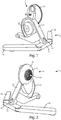
- a cycling simulation device 1 is observed provided with a support frame 2 according to the present invention.
- the cycling simulation device 1 essentially comprises said support frame 2, a mechanical unit 3 for performing or simulating gym workout, an opening and closing unit 4, and an actuating unit 5 for opening and closing said support frame 2.
- the support frame 2 comprises a main support member 21 and a base 22, which said main support member 21 is fixed to.
- Said base 22 has an anchoring pin 222, which function will be better described below.
- said support frame 2 also comprises a first 23 and a second 24 arm, both pivoted about said base 22 by means of respective pins 23' and 24', and can assume a closure position, in which they are substantially parallel arranged or in close proximity to said central support member 21, as shown in particular in figures 3 and 4 , and an opening position, in which they are spaced or spaced from said central support member 21 and said base 22, as shown in particular in the figures 1 and 2 , so as to support the cycling simulation device 1.
- first 23 and said second 24 arm have a respective end stop surface 231 and 241, as shown in particular in figure 10 , which operation will be better described below.
- Said base 22 and said first 23 and second 24 arm form, as it is seen, the support plane of the cycling simulation device 1.
- Said mechanical simulation unit 3 is fixed to said main support member 21 and includes a sprocket set 31 keyed on a shaft 32, a pulley 33 also keyed on said shaft 32, and a flywheel (not shown in the figure) connected with said pulley by means of suitable transmission means, such as a belt and the like.
- Said mechanical simulation unit 3 also includes braking members acting on said flywheel (not shown).
- the carter 34 is shown, which protects said flywheel.
- the opening and closing unit 4 comprises a button 41, pivoted about a pin 411 to said base 22 of said frame 2, and an elastic member 42, such as a compensation spring, which, in the shown embodiment, is a plate made of harmonic steel, capable of compensating mechanical plays between the different elements of said opening and closing unit 4, which operation will be better explained below.
- Said opening and closing unit 4 also includes a lever 43, which is pressed into its central part to said base 22 by means of a pin 430, having a first end 431, on which said button 41 may act by means of said plate 42, and a second end 432, pivoted about an opening and closing pin 44, slidably movable in a seat 221, formed in said base 22 of said frame 2.
- Said opening and closing pin 44 is capable of assuming a working position, in which it is lowered with respect to said base 22, and a rest position, in which it is raised or retracted with respect to said base 22.
- a contrast spring 441 is provided, which function will be better defined in the following.
- the actuating unit 5 comprises a rod, in particular a connecting rod 51 having a hook 512, a first actuating arm 513, pivoted about a respective pin 513' to said first arm 23, and a second actuating arm 514, pivoted about a respective pin 514', to said second arm 24.
- Said connecting rod 51, said base 22 and said first 23 and second 24 arm provide an articulated system, such that the movement by the user of one of said first 23 and second 24 arm also causes the other arm to move accordingly due to the roto-translation of said connecting rod 51, with respect to said base 22, which joins said first 23 and second 24 arm.
- Said first arm 23, second arm 24 and connecting rod 51 all move with respect to said base 22.
- Said connecting rod 51 has a first cavity 511 and a second cavity 515, which said opening and closing pin 44 is capable of engaging with.
- the actuation unit 5 also comprises an opening spring 52, arranged and hooked to said hook 512 and said anchoring pin 222 of said base 22 or of said frame 2 in general, to accompany the opening of said frame 2.
- the opening and closing pin 44 is in said working position, i.e. lowered, interfering with said first cavity 511 of said connecting rod 51 and it is kept in this working position by the action of the contrast spring 441.
- the opening spring 52 is extended and preloaded, as shown in figure 9 , and said first 23 and second 24 arm are substantially parallel, as shown in figures 3 or 4 .
- the user presses the button 41 by exerting a force in the direction of the arrow A, so as to exert a stress on the first end 431 of the lever 43 by means of said plate 42, which compensates for any mechanical play between said button 41 and said lever 43.
- Said plate 42 is not required to produce the stress of said first end 431 but it is exclusively for the adjustment of construction tolerances.
- the user After pressing said button 41, the user also opens one of said first 23 or second 24 arm, by moving it externally with respect to said central member 21 or said base 22.
- said lever 43 has the fulcrum in the center by means of said pin 430, said second end 432 lifts, winning the force opposed by said contrast spring 441, thereby lifting the release pin 44, which moves in the direction of the arrow B, so as to assume said retracted position, disengaging from said first cavity 511.
- the length of the actuator arms 513 and 514 of the rod 51 and the shape of the stop surfaces 231 and 232, respectively of said first 23 and second 24 arms are such as to allow a slightly larger opening than the arm 23, corresponding to the side on which the sprocket set 31 is arranged, to allow a greater stability of the cycling simulation device 1 during the user's pedaling.
Landscapes
- Health & Medical Sciences (AREA)
- General Health & Medical Sciences (AREA)
- Physical Education & Sports Medicine (AREA)
- Cardiology (AREA)
- Vascular Medicine (AREA)
- Transmission Devices (AREA)
- Closing And Opening Devices For Wings, And Checks For Wings (AREA)
- Jib Cranes (AREA)
- Supply And Installment Of Electrical Components (AREA)
- Rehabilitation Tools (AREA)
- Body Structure For Vehicles (AREA)
- Pivots And Pivotal Connections (AREA)
- Life Sciences & Earth Sciences (AREA)
- Biophysics (AREA)
- Orthopedic Medicine & Surgery (AREA)
- Seats For Vehicles (AREA)
Claims (13)
- Cadre de support (2) pour un appareil de gymnastique, en particulier pour un dispositif de simulation de cyclisme (1), comprenant :une base (22) ; etun premier bras (23) articulé avec ladite base (22) et un second bras (24) articulé avec ladite base (22), de sorte que lesdits premier (23) et second (24) bras puissent prendre une position fermée et une position ouverte, en rotation par rapport à ladite base (22),caractérisé en ce queledit cadre de support (2) comprend un élément d'articulation (51) articulé avec ladite base (22) et lesdits premier (23) et second (24) bras de sorte que la rotation de l'un desdits premier (23) ou second (24) bras par rapport à ladite base (22) provoque une translation en rotation dudit corps d'articulation (51) et la rotation de l'autre bras (23, 24) par rapport à ladite base (22), provoquant le passage de ladite position fermée à ladite position ouverte ou inversement.
- Cadre de support (2) selon la revendication précédente, caractérisé en ce que ledit élément d'articulation est une barre de raccordement (51).
- Cadre de support (2) selon la revendication précédente, caractérisé en ce que ladite barre de raccordement (51) comporte un premier bras d'actionnement (513), pivoté par rapport audit premier bras (23), et un second bras d'actionnement (514), pivoté par rapport audit second bras (24).
- Cadre de support (2) selon l'une quelconque des revendications 2 et/ou 3, caractérisé en ce queladite barre de raccordement (51) comprend un crochet (512) eten ce qu'elle comporte un ressort d'ouverture (52), accroché audit crochet (512) et audit cadre de support (2) ou à ladite base (22) ou à une broche d'ancrage (222) de ladite base (22), ledit ressort d'ouverture (52) accumulant de l'énergie potentielle lorsque ledit cadre de support (2) est dans la position fermée, et libérant ladite énergie potentielle en facilitant la translation en rotation de ladite barre de raccordement (51).
- Cadre de support (2) selon l'une quelconque des revendications précédentes, caractérisé en ce que ledit premier (23) et ledit second bras (24) ont une surface de butée respective (231, 241), lesdits premier (23) et second (24) bras ouverts jusqu'à ce que ledit premier bras d'actionnement (513) et ledit second bras d'actionnement (514) dudit corps d'articulation (51) arrivent à proximité respectivement de ladite surface de butée d'extrémité (231) dudit premier bras (23) et de ladite la surface de butée d'extrémité (241) dudit second bras (24).
- Cadre de support (2) selon l'une quelconque des revendications précédentes, caractérisé en ce que ledit élément d'articulation (51), ladite base (22) et lesdits premier (23) et second (24) bras sont articulés de manière à permettre la plus grande ouverture de l'un desdits bras (23, 24) l'un par rapport à l'autre.
- Cadre de support (2) selon l'une quelconque des revendications précédentes, caractériséen ce qu'il comporte une unité d'ouverture et de fermeture (4) coopérant avec ledit élément d'articulation (51), de manière à le bloquer en position lorsque lesdits premier (23) et second (24) bras adoptent lesdites positions de fermeture et d'ouverture.
- Cadre de support (2) selon la revendication précédente, caractérisé en ce que ladite unité d'ouverture et de fermeture (4) comprendun bouton (41),un levier (43), pivoté par rapport à ladite base (2) à l'aide d'une broche respective (430), ayant une première extrémité (431), sur laquelle ledit bouton (41) peut interagir du fait d'une sollicitation, et une seconde extrémité (432) ;une broche d'ouverture et de fermeture (44), pivotée vers ladite seconde extrémité (432) dudit levier (43), ladite broche d'ouverture et de fermeture (44) pouvant adopter une position de travail et une position de repos ;un ressort de contraste (441) agencé de manière à exercer une force pour maintenir ladite broche d'ouverture et de fermeture (44) dans ladite position de travail, eten ce que ledit élément d'articulation (51) a une première cavité (511) et une seconde cavité (515), avec lesquelles ladite broche d'ouverture et de fermeture (44) est insérée ou interfère lorsqu'elle est dans ladite position de travail, respectivement dans lesdites position fermée et ouverte desdits premier (23) et second (24) bras.
- Cadre de support (2) selon la revendication précédente, caractérisé en ce queladite base (22) présente un siège (221),en ce que ladite broche d'ouverture et de fermeture (44) est déplaçable de manière coulissante dans ledit siège (221), eten ce que ledit ressort de contraste (441) est interposé entre ledit siège (221) et ladite broche d'ouverture et de fermeture (44).
- Cadre de support (2) selon l'une quelconque des revendications 8 et/ou 9, caractérisé en ce qu'il comporte un élément élastique (42), disposé entre ledit bouton (41) et ladite première extrémité (431) dudit levier (43), ledit élément élastique (42) étant adapté à compenser des jeux mécaniques.
- Cadre de support (2) selon la revendication précédente, caractérisé en ce que ledit élément élastique (42) est un ressort ou une plaque en acier harmonique.
- Cadre de support (2) selon l'une quelconque des revendications précédentes, caractérisé en ce qu'il comporte un élément de support principal (21), d'un seul tenant avec ladite base (22), sur lequel est installée une unité mécanique (3) pour l'exécution ou la simulation d'un exercice de gymnastique, tel qu'un simulateur de cyclisme.
- Dispositif de simulation de cyclisme comprenant :un cadre de support (2) selon l'une quelconque des revendications 1 à 12 etune unité mécanique (3) pour l'exécution ou la simulation de l'exercice de gymnastique, installé sur ledit cadre de support (2), comprenant un jeu de pignons (31) calé sur un arbre (32), une poulie (33) calée sur ledit arbre (32), une roue libre, reliée par des éléments de transmission à ladite poulie (33), tel qu'une courroie ou similaire, et des éléments de freinage agissant sur ladite roue libre.
Applications Claiming Priority (1)
| Application Number | Priority Date | Filing Date | Title |
|---|---|---|---|
| IT102016000068777A IT201600068777A1 (it) | 2016-07-01 | 2016-07-01 | Telaio di supporto per una macchina ginnica, in particolare per un dispositivo di simulazione ciclistica. |
Publications (2)
| Publication Number | Publication Date |
|---|---|
| EP3263192A1 EP3263192A1 (fr) | 2018-01-03 |
| EP3263192B1 true EP3263192B1 (fr) | 2019-02-06 |
Family
ID=57609949
Family Applications (1)
| Application Number | Title | Priority Date | Filing Date |
|---|---|---|---|
| EP17177802.0A Active EP3263192B1 (fr) | 2016-07-01 | 2017-06-26 | Cadre de support pour un appareil de gymnastique, en particulier pour un dispositif de simulation de cyclisme |
Country Status (4)
| Country | Link |
|---|---|
| US (1) | US10434364B2 (fr) |
| EP (1) | EP3263192B1 (fr) |
| CN (1) | CN107551516B (fr) |
| IT (1) | IT201600068777A1 (fr) |
Families Citing this family (4)
| Publication number | Priority date | Publication date | Assignee | Title |
|---|---|---|---|---|
| US10722414B2 (en) * | 2017-11-01 | 2020-07-28 | Alex Bush | Exercising device |
| USD900257S1 (en) * | 2018-08-14 | 2020-10-27 | Kurt Manufacturing Company, Inc. | Bicycle trainer |
| USD1004716S1 (en) * | 2022-03-09 | 2023-11-14 | Saris Equipment, Llc | Direct drive bicycle trainer |
| TWI863844B (zh) * | 2024-03-15 | 2024-11-21 | 力山工業股份有限公司 | 具有較少材積的健身器材 |
Family Cites Families (15)
| Publication number | Priority date | Publication date | Assignee | Title |
|---|---|---|---|---|
| US1621120A (en) * | 1925-09-10 | 1927-03-15 | Robert E Lee | Home trainer |
| US3259385A (en) * | 1964-02-27 | 1966-07-05 | Ben E Boren | Portable exercising device |
| IL59291A (en) * | 1980-02-03 | 1982-11-30 | Biran Benjamin | Foot-operated exercising device |
| US5480366A (en) * | 1994-03-17 | 1996-01-02 | Harnden; Eric F. | Stationary bicycle trainer |
| US6780143B2 (en) * | 2001-12-31 | 2004-08-24 | Victor Z. Copeland | Eccentric cycling trainer |
| CN2522108Y (zh) * | 2002-01-09 | 2002-11-27 | 继强国际有限公司 | 兼具支撑与导滑功能的跑步机支架 |
| JP2007296080A (ja) * | 2006-04-28 | 2007-11-15 | Atex Co Ltd | 身体鍛錬器 |
| ITVI20060227A1 (it) * | 2006-07-18 | 2008-01-19 | Elite Srl | Assieme freno magnetico bilanciato per dispositivo da allenamento ciclistico |
| ITTO20070123A1 (it) * | 2007-02-21 | 2008-08-22 | Cosmed Engineering S R L | "kit portatile, dispositivo e procedimento per l esecuzione di test cardiopolmonari sotto sforzo, con l uso di una normale bicicletta" |
| US7727124B1 (en) * | 2008-05-06 | 2010-06-01 | Saris Cycling Group, Inc. | Foldable and camming pivot mount for a resistance unit in a bicycle trainer |
| CN202387191U (zh) * | 2011-08-26 | 2012-08-22 | 廖赖淑琼 | 自行车训练器 |
| US9999818B2 (en) * | 2012-08-27 | 2018-06-19 | Wahoo Fitness Llc | Bicycle trainer |
| US20150051054A1 (en) * | 2013-08-13 | 2015-02-19 | Todd Barnhill | Exercise device for action sports training |
| CN204337641U (zh) * | 2015-01-15 | 2015-05-20 | 河北大学 | 自行车室内训练器 |
| CN205323094U (zh) * | 2016-01-06 | 2016-06-22 | 山西机电职业技术学院 | 多功能健身车 |
-
2016
- 2016-07-01 IT IT102016000068777A patent/IT201600068777A1/it unknown
-
2017
- 2017-06-23 US US15/631,587 patent/US10434364B2/en active Active
- 2017-06-26 EP EP17177802.0A patent/EP3263192B1/fr active Active
- 2017-07-03 CN CN201710533677.5A patent/CN107551516B/zh not_active Expired - Fee Related
Non-Patent Citations (1)
| Title |
|---|
| None * |
Also Published As
| Publication number | Publication date |
|---|---|
| CN107551516B (zh) | 2020-12-04 |
| IT201600068777A1 (it) | 2018-01-01 |
| US20180001136A1 (en) | 2018-01-04 |
| EP3263192A1 (fr) | 2018-01-03 |
| CN107551516A (zh) | 2018-01-09 |
| US10434364B2 (en) | 2019-10-08 |
Similar Documents
| Publication | Publication Date | Title |
|---|---|---|
| US10434364B2 (en) | Support frame for a gymnastic apparatus, particularly for a cycling simulation device | |
| US20230078801A1 (en) | Exercise Machine Tension Device Securing System | |
| US20160310782A1 (en) | Cam and wedge barbell clip | |
| US20080051262A1 (en) | Variable weight device | |
| US7775946B2 (en) | Multifunctional trainer for strength training | |
| US20030207740A1 (en) | Balanced stackable dumbbell system | |
| US20120065035A1 (en) | Multifunction fitness device | |
| US20140336017A1 (en) | Exercise device | |
| US20260041951A1 (en) | Adjustable arm on an exercise device | |
| US4989859A (en) | Method for testing and/or exercising the rotary neck muscles of the human body | |
| US7811204B2 (en) | Assisted rope climbing apparatus | |
| JP7471023B2 (ja) | 腕力器 | |
| US5118098A (en) | Method for testing and/or exercising the rotary neck muscles of the human body | |
| JP2009509628A (ja) | 筋力トレーニングおよびリハビリテーション用トレーニングマシーン | |
| US7503881B2 (en) | Exercise apparatus with weight stacks and elastic bands | |
| US10792531B1 (en) | Resistance training exercise machines having inertial switch-actuated dampening device | |
| JP6543266B2 (ja) | エクササイズ装置用調節可能カム | |
| CN101801468A (zh) | 健身设备的阻尼系统 | |
| KR101359993B1 (ko) | 웨이트 운동기구의 중량 부하 조절 장치 | |
| WO2008013750A1 (fr) | Dispositif à masses variables | |
| EP2239021B1 (fr) | Dispositif d'exercice ajustable au poids | |
| JPH0123488Y2 (fr) | ||
| MC1593A1 (fr) | Appareil de musculation a poids,a commande a distance de selection de charges a palette de maintien pour les membres du corps comportant un moyen de debrayage des charges qui permet de positionner,avant l'effort,les leviers de manoeuvre | |
| JP6639826B2 (ja) | 筋力訓練機 | |
| CN115003391A (zh) | 健身器材、重量调整装置、用于调整健身器材上的重量的方法以及重量调整环 |
Legal Events
| Date | Code | Title | Description |
|---|---|---|---|
| PUAI | Public reference made under article 153(3) epc to a published international application that has entered the european phase |
Free format text: ORIGINAL CODE: 0009012 |
|
| STAA | Information on the status of an ep patent application or granted ep patent |
Free format text: STATUS: THE APPLICATION HAS BEEN PUBLISHED |
|
| AK | Designated contracting states |
Kind code of ref document: A1 Designated state(s): AL AT BE BG CH CY CZ DE DK EE ES FI FR GB GR HR HU IE IS IT LI LT LU LV MC MK MT NL NO PL PT RO RS SE SI SK SM TR |
|
| AX | Request for extension of the european patent |
Extension state: BA ME |
|
| STAA | Information on the status of an ep patent application or granted ep patent |
Free format text: STATUS: REQUEST FOR EXAMINATION WAS MADE |
|
| 17P | Request for examination filed |
Effective date: 20180615 |
|
| RBV | Designated contracting states (corrected) |
Designated state(s): AL AT BE BG CH CY CZ DE DK EE ES FI FR GB GR HR HU IE IS IT LI LT LU LV MC MK MT NL NO PL PT RO RS SE SI SK SM TR |
|
| GRAP | Despatch of communication of intention to grant a patent |
Free format text: ORIGINAL CODE: EPIDOSNIGR1 |
|
| STAA | Information on the status of an ep patent application or granted ep patent |
Free format text: STATUS: GRANT OF PATENT IS INTENDED |
|
| RIC1 | Information provided on ipc code assigned before grant |
Ipc: A63B 21/015 20060101ALI20181023BHEP Ipc: A63B 21/22 20060101ALI20181023BHEP Ipc: A63B 21/00 20060101ALI20181023BHEP Ipc: A63B 22/06 20060101ALI20181023BHEP Ipc: A63B 69/16 20060101AFI20181023BHEP |
|
| GRAS | Grant fee paid |
Free format text: ORIGINAL CODE: EPIDOSNIGR3 |
|
| INTG | Intention to grant announced |
Effective date: 20181128 |
|
| GRAA | (expected) grant |
Free format text: ORIGINAL CODE: 0009210 |
|
| STAA | Information on the status of an ep patent application or granted ep patent |
Free format text: STATUS: THE PATENT HAS BEEN GRANTED |
|
| AK | Designated contracting states |
Kind code of ref document: B1 Designated state(s): AL AT BE BG CH CY CZ DE DK EE ES FI FR GB GR HR HU IE IS IT LI LT LU LV MC MK MT NL NO PL PT RO RS SE SI SK SM TR |
|
| REG | Reference to a national code |
Ref country code: GB Ref legal event code: FG4D |
|
| REG | Reference to a national code |
Ref country code: CH Ref legal event code: EP Ref country code: AT Ref legal event code: REF Ref document number: 1094487 Country of ref document: AT Kind code of ref document: T Effective date: 20190215 |
|
| REG | Reference to a national code |
Ref country code: IE Ref legal event code: FG4D |
|
| REG | Reference to a national code |
Ref country code: DE Ref legal event code: R096 Ref document number: 602017002061 Country of ref document: DE |
|
| REG | Reference to a national code |
Ref country code: NL Ref legal event code: MP Effective date: 20190206 |
|
| REG | Reference to a national code |
Ref country code: LT Ref legal event code: MG4D |
|
| PG25 | Lapsed in a contracting state [announced via postgrant information from national office to epo] |
Ref country code: NO Free format text: LAPSE BECAUSE OF FAILURE TO SUBMIT A TRANSLATION OF THE DESCRIPTION OR TO PAY THE FEE WITHIN THE PRESCRIBED TIME-LIMIT Effective date: 20190506 Ref country code: LT Free format text: LAPSE BECAUSE OF FAILURE TO SUBMIT A TRANSLATION OF THE DESCRIPTION OR TO PAY THE FEE WITHIN THE PRESCRIBED TIME-LIMIT Effective date: 20190206 Ref country code: FI Free format text: LAPSE BECAUSE OF FAILURE TO SUBMIT A TRANSLATION OF THE DESCRIPTION OR TO PAY THE FEE WITHIN THE PRESCRIBED TIME-LIMIT Effective date: 20190206 Ref country code: NL Free format text: LAPSE BECAUSE OF FAILURE TO SUBMIT A TRANSLATION OF THE DESCRIPTION OR TO PAY THE FEE WITHIN THE PRESCRIBED TIME-LIMIT Effective date: 20190206 Ref country code: SE Free format text: LAPSE BECAUSE OF FAILURE TO SUBMIT A TRANSLATION OF THE DESCRIPTION OR TO PAY THE FEE WITHIN THE PRESCRIBED TIME-LIMIT Effective date: 20190206 Ref country code: PT Free format text: LAPSE BECAUSE OF FAILURE TO SUBMIT A TRANSLATION OF THE DESCRIPTION OR TO PAY THE FEE WITHIN THE PRESCRIBED TIME-LIMIT Effective date: 20190606 Ref country code: ES Free format text: LAPSE BECAUSE OF FAILURE TO SUBMIT A TRANSLATION OF THE DESCRIPTION OR TO PAY THE FEE WITHIN THE PRESCRIBED TIME-LIMIT Effective date: 20190206 |
|
| REG | Reference to a national code |
Ref country code: AT Ref legal event code: MK05 Ref document number: 1094487 Country of ref document: AT Kind code of ref document: T Effective date: 20190206 |
|
| PG25 | Lapsed in a contracting state [announced via postgrant information from national office to epo] |
Ref country code: RS Free format text: LAPSE BECAUSE OF FAILURE TO SUBMIT A TRANSLATION OF THE DESCRIPTION OR TO PAY THE FEE WITHIN THE PRESCRIBED TIME-LIMIT Effective date: 20190206 Ref country code: GR Free format text: LAPSE BECAUSE OF FAILURE TO SUBMIT A TRANSLATION OF THE DESCRIPTION OR TO PAY THE FEE WITHIN THE PRESCRIBED TIME-LIMIT Effective date: 20190507 Ref country code: BG Free format text: LAPSE BECAUSE OF FAILURE TO SUBMIT A TRANSLATION OF THE DESCRIPTION OR TO PAY THE FEE WITHIN THE PRESCRIBED TIME-LIMIT Effective date: 20190506 Ref country code: LV Free format text: LAPSE BECAUSE OF FAILURE TO SUBMIT A TRANSLATION OF THE DESCRIPTION OR TO PAY THE FEE WITHIN THE PRESCRIBED TIME-LIMIT Effective date: 20190206 Ref country code: IS Free format text: LAPSE BECAUSE OF FAILURE TO SUBMIT A TRANSLATION OF THE DESCRIPTION OR TO PAY THE FEE WITHIN THE PRESCRIBED TIME-LIMIT Effective date: 20190606 Ref country code: HR Free format text: LAPSE BECAUSE OF FAILURE TO SUBMIT A TRANSLATION OF THE DESCRIPTION OR TO PAY THE FEE WITHIN THE PRESCRIBED TIME-LIMIT Effective date: 20190206 |
|
| PG25 | Lapsed in a contracting state [announced via postgrant information from national office to epo] |
Ref country code: DK Free format text: LAPSE BECAUSE OF FAILURE TO SUBMIT A TRANSLATION OF THE DESCRIPTION OR TO PAY THE FEE WITHIN THE PRESCRIBED TIME-LIMIT Effective date: 20190206 Ref country code: AL Free format text: LAPSE BECAUSE OF FAILURE TO SUBMIT A TRANSLATION OF THE DESCRIPTION OR TO PAY THE FEE WITHIN THE PRESCRIBED TIME-LIMIT Effective date: 20190206 Ref country code: SK Free format text: LAPSE BECAUSE OF FAILURE TO SUBMIT A TRANSLATION OF THE DESCRIPTION OR TO PAY THE FEE WITHIN THE PRESCRIBED TIME-LIMIT Effective date: 20190206 Ref country code: RO Free format text: LAPSE BECAUSE OF FAILURE TO SUBMIT A TRANSLATION OF THE DESCRIPTION OR TO PAY THE FEE WITHIN THE PRESCRIBED TIME-LIMIT Effective date: 20190206 Ref country code: EE Free format text: LAPSE BECAUSE OF FAILURE TO SUBMIT A TRANSLATION OF THE DESCRIPTION OR TO PAY THE FEE WITHIN THE PRESCRIBED TIME-LIMIT Effective date: 20190206 Ref country code: CZ Free format text: LAPSE BECAUSE OF FAILURE TO SUBMIT A TRANSLATION OF THE DESCRIPTION OR TO PAY THE FEE WITHIN THE PRESCRIBED TIME-LIMIT Effective date: 20190206 |
|
| REG | Reference to a national code |
Ref country code: DE Ref legal event code: R097 Ref document number: 602017002061 Country of ref document: DE |
|
| PG25 | Lapsed in a contracting state [announced via postgrant information from national office to epo] |
Ref country code: SM Free format text: LAPSE BECAUSE OF FAILURE TO SUBMIT A TRANSLATION OF THE DESCRIPTION OR TO PAY THE FEE WITHIN THE PRESCRIBED TIME-LIMIT Effective date: 20190206 Ref country code: PL Free format text: LAPSE BECAUSE OF FAILURE TO SUBMIT A TRANSLATION OF THE DESCRIPTION OR TO PAY THE FEE WITHIN THE PRESCRIBED TIME-LIMIT Effective date: 20190206 |
|
| PLBE | No opposition filed within time limit |
Free format text: ORIGINAL CODE: 0009261 |
|
| STAA | Information on the status of an ep patent application or granted ep patent |
Free format text: STATUS: NO OPPOSITION FILED WITHIN TIME LIMIT |
|
| PG25 | Lapsed in a contracting state [announced via postgrant information from national office to epo] |
Ref country code: AT Free format text: LAPSE BECAUSE OF FAILURE TO SUBMIT A TRANSLATION OF THE DESCRIPTION OR TO PAY THE FEE WITHIN THE PRESCRIBED TIME-LIMIT Effective date: 20190206 |
|
| 26N | No opposition filed |
Effective date: 20191107 |
|
| PG25 | Lapsed in a contracting state [announced via postgrant information from national office to epo] |
Ref country code: MC Free format text: LAPSE BECAUSE OF FAILURE TO SUBMIT A TRANSLATION OF THE DESCRIPTION OR TO PAY THE FEE WITHIN THE PRESCRIBED TIME-LIMIT Effective date: 20190206 |
|
| PG25 | Lapsed in a contracting state [announced via postgrant information from national office to epo] |
Ref country code: SI Free format text: LAPSE BECAUSE OF FAILURE TO SUBMIT A TRANSLATION OF THE DESCRIPTION OR TO PAY THE FEE WITHIN THE PRESCRIBED TIME-LIMIT Effective date: 20190206 |
|
| REG | Reference to a national code |
Ref country code: BE Ref legal event code: MM Effective date: 20190630 |
|
| PG25 | Lapsed in a contracting state [announced via postgrant information from national office to epo] |
Ref country code: TR Free format text: LAPSE BECAUSE OF FAILURE TO SUBMIT A TRANSLATION OF THE DESCRIPTION OR TO PAY THE FEE WITHIN THE PRESCRIBED TIME-LIMIT Effective date: 20190206 |
|
| PG25 | Lapsed in a contracting state [announced via postgrant information from national office to epo] |
Ref country code: IE Free format text: LAPSE BECAUSE OF NON-PAYMENT OF DUE FEES Effective date: 20190626 |
|
| PG25 | Lapsed in a contracting state [announced via postgrant information from national office to epo] |
Ref country code: LU Free format text: LAPSE BECAUSE OF NON-PAYMENT OF DUE FEES Effective date: 20190626 Ref country code: BE Free format text: LAPSE BECAUSE OF NON-PAYMENT OF DUE FEES Effective date: 20190630 |
|
| PG25 | Lapsed in a contracting state [announced via postgrant information from national office to epo] |
Ref country code: FR Free format text: LAPSE BECAUSE OF NON-PAYMENT OF DUE FEES Effective date: 20190630 |
|
| REG | Reference to a national code |
Ref country code: CH Ref legal event code: PL |
|
| PG25 | Lapsed in a contracting state [announced via postgrant information from national office to epo] |
Ref country code: CH Free format text: LAPSE BECAUSE OF NON-PAYMENT OF DUE FEES Effective date: 20200630 Ref country code: LI Free format text: LAPSE BECAUSE OF NON-PAYMENT OF DUE FEES Effective date: 20200630 |
|
| PG25 | Lapsed in a contracting state [announced via postgrant information from national office to epo] |
Ref country code: CY Free format text: LAPSE BECAUSE OF FAILURE TO SUBMIT A TRANSLATION OF THE DESCRIPTION OR TO PAY THE FEE WITHIN THE PRESCRIBED TIME-LIMIT Effective date: 20190206 |
|
| PG25 | Lapsed in a contracting state [announced via postgrant information from national office to epo] |
Ref country code: HU Free format text: LAPSE BECAUSE OF FAILURE TO SUBMIT A TRANSLATION OF THE DESCRIPTION OR TO PAY THE FEE WITHIN THE PRESCRIBED TIME-LIMIT; INVALID AB INITIO Effective date: 20170626 Ref country code: MT Free format text: LAPSE BECAUSE OF FAILURE TO SUBMIT A TRANSLATION OF THE DESCRIPTION OR TO PAY THE FEE WITHIN THE PRESCRIBED TIME-LIMIT Effective date: 20190206 |
|
| PG25 | Lapsed in a contracting state [announced via postgrant information from national office to epo] |
Ref country code: MK Free format text: LAPSE BECAUSE OF FAILURE TO SUBMIT A TRANSLATION OF THE DESCRIPTION OR TO PAY THE FEE WITHIN THE PRESCRIBED TIME-LIMIT Effective date: 20190206 |
|
| PGFP | Annual fee paid to national office [announced via postgrant information from national office to epo] |
Ref country code: DE Payment date: 20250626 Year of fee payment: 9 |
|
| PGFP | Annual fee paid to national office [announced via postgrant information from national office to epo] |
Ref country code: GB Payment date: 20250617 Year of fee payment: 9 |
|
| PGFP | Annual fee paid to national office [announced via postgrant information from national office to epo] |
Ref country code: IT Payment date: 20250623 Year of fee payment: 9 |