EP3263189B1 - Verbessertes steuerungssystem einer radfahrsimulationsvorrichtung - Google Patents
Verbessertes steuerungssystem einer radfahrsimulationsvorrichtung Download PDFInfo
- Publication number
- EP3263189B1 EP3263189B1 EP17177807.9A EP17177807A EP3263189B1 EP 3263189 B1 EP3263189 B1 EP 3263189B1 EP 17177807 A EP17177807 A EP 17177807A EP 3263189 B1 EP3263189 B1 EP 3263189B1
- Authority
- EP
- European Patent Office
- Prior art keywords
- arm
- flywheel
- user
- control logic
- logic unit
- Prior art date
- Legal status (The legal status is an assumption and is not a legal conclusion. Google has not performed a legal analysis and makes no representation as to the accuracy of the status listed.)
- Active
Links
Images






Classifications
-
- A—HUMAN NECESSITIES
- A63—SPORTS; GAMES; AMUSEMENTS
- A63B—APPARATUS FOR PHYSICAL TRAINING, GYMNASTICS, SWIMMING, CLIMBING, OR FENCING; BALL GAMES; TRAINING EQUIPMENT
- A63B24/00—Electric or electronic controls for exercising apparatus of preceding groups; Controlling or monitoring of exercises, sportive games, training or athletic performances
- A63B24/0087—Electric or electronic controls for exercising apparatus of groups A63B21/00 - A63B23/00, e.g. controlling load
-
- A—HUMAN NECESSITIES
- A63—SPORTS; GAMES; AMUSEMENTS
- A63B—APPARATUS FOR PHYSICAL TRAINING, GYMNASTICS, SWIMMING, CLIMBING, OR FENCING; BALL GAMES; TRAINING EQUIPMENT
- A63B21/00—Exercising apparatus for developing or strengthening the muscles or joints of the body by working against a counterforce, with or without measuring devices
- A63B21/005—Exercising apparatus for developing or strengthening the muscles or joints of the body by working against a counterforce, with or without measuring devices using electromagnetic or electric force-resisters
- A63B21/0051—Exercising apparatus for developing or strengthening the muscles or joints of the body by working against a counterforce, with or without measuring devices using electromagnetic or electric force-resisters using eddy currents induced in moved elements, e.g. by permanent magnets
-
- A—HUMAN NECESSITIES
- A63—SPORTS; GAMES; AMUSEMENTS
- A63B—APPARATUS FOR PHYSICAL TRAINING, GYMNASTICS, SWIMMING, CLIMBING, OR FENCING; BALL GAMES; TRAINING EQUIPMENT
- A63B21/00—Exercising apparatus for developing or strengthening the muscles or joints of the body by working against a counterforce, with or without measuring devices
- A63B21/005—Exercising apparatus for developing or strengthening the muscles or joints of the body by working against a counterforce, with or without measuring devices using electromagnetic or electric force-resisters
- A63B21/0057—Exercising apparatus for developing or strengthening the muscles or joints of the body by working against a counterforce, with or without measuring devices using electromagnetic or electric force-resisters using electromagnetic clutches
-
- A—HUMAN NECESSITIES
- A63—SPORTS; GAMES; AMUSEMENTS
- A63B—APPARATUS FOR PHYSICAL TRAINING, GYMNASTICS, SWIMMING, CLIMBING, OR FENCING; BALL GAMES; TRAINING EQUIPMENT
- A63B21/00—Exercising apparatus for developing or strengthening the muscles or joints of the body by working against a counterforce, with or without measuring devices
- A63B21/005—Exercising apparatus for developing or strengthening the muscles or joints of the body by working against a counterforce, with or without measuring devices using electromagnetic or electric force-resisters
- A63B21/0058—Exercising apparatus for developing or strengthening the muscles or joints of the body by working against a counterforce, with or without measuring devices using electromagnetic or electric force-resisters using motors
-
- A—HUMAN NECESSITIES
- A63—SPORTS; GAMES; AMUSEMENTS
- A63B—APPARATUS FOR PHYSICAL TRAINING, GYMNASTICS, SWIMMING, CLIMBING, OR FENCING; BALL GAMES; TRAINING EQUIPMENT
- A63B21/00—Exercising apparatus for developing or strengthening the muscles or joints of the body by working against a counterforce, with or without measuring devices
- A63B21/22—Resisting devices with rotary bodies
- A63B21/225—Resisting devices with rotary bodies with flywheels
-
- A—HUMAN NECESSITIES
- A63—SPORTS; GAMES; AMUSEMENTS
- A63B—APPARATUS FOR PHYSICAL TRAINING, GYMNASTICS, SWIMMING, CLIMBING, OR FENCING; BALL GAMES; TRAINING EQUIPMENT
- A63B21/00—Exercising apparatus for developing or strengthening the muscles or joints of the body by working against a counterforce, with or without measuring devices
- A63B21/40—Interfaces with the user related to strength training; Details thereof
- A63B21/4027—Specific exercise interfaces
- A63B21/4033—Handles, pedals, bars or platforms
- A63B21/4034—Handles, pedals, bars or platforms for operation by feet
-
- A—HUMAN NECESSITIES
- A63—SPORTS; GAMES; AMUSEMENTS
- A63B—APPARATUS FOR PHYSICAL TRAINING, GYMNASTICS, SWIMMING, CLIMBING, OR FENCING; BALL GAMES; TRAINING EQUIPMENT
- A63B22/00—Exercising apparatus specially adapted for conditioning the cardio-vascular system, for training agility or co-ordination of movements
- A63B22/06—Exercising apparatus specially adapted for conditioning the cardio-vascular system, for training agility or co-ordination of movements with support elements performing a rotating cycling movement, i.e. a closed path movement
- A63B22/0605—Exercising apparatus specially adapted for conditioning the cardio-vascular system, for training agility or co-ordination of movements with support elements performing a rotating cycling movement, i.e. a closed path movement performing a circular movement, e.g. ergometers
-
- A—HUMAN NECESSITIES
- A63—SPORTS; GAMES; AMUSEMENTS
- A63B—APPARATUS FOR PHYSICAL TRAINING, GYMNASTICS, SWIMMING, CLIMBING, OR FENCING; BALL GAMES; TRAINING EQUIPMENT
- A63B23/00—Exercising apparatus specially adapted for particular parts of the body
- A63B23/035—Exercising apparatus specially adapted for particular parts of the body for limbs, i.e. upper or lower limbs, e.g. simultaneously
- A63B23/04—Exercising apparatus specially adapted for particular parts of the body for limbs, i.e. upper or lower limbs, e.g. simultaneously for lower limbs
-
- A—HUMAN NECESSITIES
- A63—SPORTS; GAMES; AMUSEMENTS
- A63B—APPARATUS FOR PHYSICAL TRAINING, GYMNASTICS, SWIMMING, CLIMBING, OR FENCING; BALL GAMES; TRAINING EQUIPMENT
- A63B71/00—Games or sports accessories not covered in groups A63B1/00 - A63B69/00
- A63B71/06—Indicating or scoring devices for games or players, or for other sports activities
- A63B71/0619—Displays, user interfaces and indicating devices, specially adapted for sport equipment, e.g. display mounted on treadmills
- A63B71/0622—Visual, audio or audio-visual systems for entertaining, instructing or motivating the user
-
- A—HUMAN NECESSITIES
- A63—SPORTS; GAMES; AMUSEMENTS
- A63B—APPARATUS FOR PHYSICAL TRAINING, GYMNASTICS, SWIMMING, CLIMBING, OR FENCING; BALL GAMES; TRAINING EQUIPMENT
- A63B21/00—Exercising apparatus for developing or strengthening the muscles or joints of the body by working against a counterforce, with or without measuring devices
- A63B21/00058—Mechanical means for varying the resistance
- A63B21/00069—Setting or adjusting the resistance level; Compensating for a preload prior to use, e.g. changing length of resistance or adjusting a valve
-
- A—HUMAN NECESSITIES
- A63—SPORTS; GAMES; AMUSEMENTS
- A63B—APPARATUS FOR PHYSICAL TRAINING, GYMNASTICS, SWIMMING, CLIMBING, OR FENCING; BALL GAMES; TRAINING EQUIPMENT
- A63B2220/00—Measuring of physical parameters relating to sporting activity
- A63B2220/20—Distances or displacements
-
- A—HUMAN NECESSITIES
- A63—SPORTS; GAMES; AMUSEMENTS
- A63B—APPARATUS FOR PHYSICAL TRAINING, GYMNASTICS, SWIMMING, CLIMBING, OR FENCING; BALL GAMES; TRAINING EQUIPMENT
- A63B2220/00—Measuring of physical parameters relating to sporting activity
- A63B2220/50—Force related parameters
- A63B2220/54—Torque
-
- A—HUMAN NECESSITIES
- A63—SPORTS; GAMES; AMUSEMENTS
- A63B—APPARATUS FOR PHYSICAL TRAINING, GYMNASTICS, SWIMMING, CLIMBING, OR FENCING; BALL GAMES; TRAINING EQUIPMENT
- A63B2220/00—Measuring of physical parameters relating to sporting activity
- A63B2220/80—Special sensors, transducers or devices therefor
- A63B2220/805—Optical or opto-electronic sensors
-
- A—HUMAN NECESSITIES
- A63—SPORTS; GAMES; AMUSEMENTS
- A63B—APPARATUS FOR PHYSICAL TRAINING, GYMNASTICS, SWIMMING, CLIMBING, OR FENCING; BALL GAMES; TRAINING EQUIPMENT
- A63B2225/00—Miscellaneous features of sport apparatus, devices or equipment
- A63B2225/20—Miscellaneous features of sport apparatus, devices or equipment with means for remote communication, e.g. internet or the like
Definitions
- the present invention relates to an improved cycling simulation device.
- the invention concerns an improved cycling simulation device of the mentioned type, designed and realized in particular for setting up and controlling a training program by means of a remote device and for assessing the quality of the execution of the training program by the user himself.
- cycling simulation devices also known as cyclosimulators or cyclo-ergometers
- cyclosimulators or cyclo-ergometers allow a user to carry out stationary cycling workouts, typically in closed environments or in limited spaces, using their own racing, road or mountain bicycle type.
- a cycling simulation device typically comprises a base support or a frame, comprising a main support member, a base, to which said main support member is fixed, and two arms hinged to said base and capable of assuming a closed position, in which they are substantially parallel to each other, and an open position, in which they are spaced with respect to said central support member, so as to support the device.
- the main member supports on one side a pulley, which the sprocket set or cassette is coupled with, which is part of the transmission system of the device-bicycle set.
- Said main member on the opposite side supports a flywheel connected, by means of suitable transmission members, with said pulley, and braking members acting on said flywheel.
- a user can mount his bicycle on said simulation device just by removing the rear wheel and engaging the chain with the sprocket set, choosing the sprocket corresponding to the transmission or gear ratio to which the user intends to perform the training.
- the smaller sprockets determine a "long" transmission ratio, which is set by the user for high distances typically in the plain, while larger sprockets determine a "short” transmission ratio that is set by the user to perform high speed pedals to travel short distances.
- the user can manually adjust the opposite resistance from the pedal simulation device using cables acting directly on the brake, which acts on the flywheel.
- Simulation devices are also known, where the resistance control, and therefore the control of the brake acting on the flywheel, is remotely carried out.
- Another object of the invention is to provide an improved control system that allows the user to check the quality of his workout in real time, so as to allow any corrections during pedaling.
- a control logic unit capable of connecting in transmission and reception with a remote device, by which a user can set one or more training parameters, and a torque sensor for detecting and sending to said control logic unit a signal related to the torque acting on said main shaft during the rotation of said flywheel, and said control logic unit being configured so as to adjust the braking force exerted by said braking means on said flywheel as a function of said training parameters set by said user and of said signal related to the torque acting on said main shaft detected by said torque sensor.
- said system could comprise an optical sensor, coupled with said support frame, to detect values of the distance between at least one of the two pedals of said bicycle from the sensor itself and to send a corresponding signal to said control logic unit, for it to adjust the braking force exerted by said braking means on said flywheel as a function also of said signal.
- said control logic unit could carry out a correlation between said signal received from said torque sensor and said signal received from said optical sensor, so as to associate a value of the torque acting on said main shaft to the position of said at least one bicycle pedal.
- said support frame could comprise a central elongated arm provided with two opposite ends, to which the ends of a first, a second and a third arm are pivotally coupled, said central arm being centrally positioned between said first and second arm, an optical sensor being positioned on said third arm, on the portion that faces towards said second arm for detecting the passage of the left pedal, corresponding to the left foot of the user, of said bicycle, with respect to the optical sensor itself; and/or an optical sensor being positioned on the portion that faces towards said second arm for detecting the passage of the right pedal, corresponding to the right foot of the user, of said bicycle, with respect to the optical sensor itself.
- said remote device could show a preset graphical representation of the correlation carried out by said logic control unit of said signal received from said torque sensor and said signal received from said optical sensor.
- a cycling simulation device of the type comprising a support frame, on which coupling members are installed for coupling to the bicycle chain, with which a user carries out a training by acting on the respective pedals of said bicycle, a flywheel rotating around a main shaft, connected to said coupling members, braking means acting on said flywheel and a control logic unit, characterized in that said cycling simulation device comprises a torque sensor for detecting and sending to said control logic unit a signal as a function of the torque acting on said main shaft during the rotation of said flywheel, wherein said control logic unit is configured so as to receive a plurality of training parameters selected by said user from a remote device, and to adjust the braking force exerted by said braking means on said flywheel, as a function of said parameters set by said user and of said signal related to the torque acting on said main shaft detected by said torque sensor.
- said device could comprise an optical sensor coupled with said support frame, to detect the values of the distance between at least one of the two pedals of said bicycle from the sensor itself and to send a signal proportional to said distance values to said control logic unit, for it to adjust the braking force exerted by said braking means on said flywheel as a function also of said signal.
- said control logic unit could carry out a correlation between said signal received from said torque sensor and said signal received from said optical sensor, to associate a value of the torque acting on said main shaft to said at least one bicycle pedal.
- said support frame could be of the type comprising a central elongated arm provided with two opposite ends, to which the ends of a first and a second and a third arm are pivotally coupled, said central arm being centrally positioned between said first and second arm, said optical sensor being positioned on said third arm in the portion that faces towards said second arm for detecting the passage of the left pedal of said bicycle.
- said support frame could be of the type comprising a central elongated arm provided with two opposite ends, to which the ends of a first and a second and a third arm are pivotally coupled, said central arm being centrally positioned between said first and second arm, said optical sensor being positioned on said third arm on the portion that faces towards said second arm for detecting the passage of the right pedal of said bicycle.
- said braking means could comprise at least one permanent magnet, a magnet holder bracket housing said at least one permanent magnet, said magnet holder bracket being capable of assuming an inactive position, in which said at least one permanent magnet does not overlap over said flywheel, and an active position, in which said at least one permanent magnet is at least partially overlapped over said flywheel, and a motor, connected to, and controlled by said control logic unit, said motor being arranged for causing said magnet holder bracket to pass from said inactive position to an active position and vice-versa.
- said magnet holder bracket could be pivoted about a pivot
- said braking means could comprise a worm screw, arranged to be rotated by said motor, and a nut screw, engaged with said worm screw, said nut screw being integral with, or fixed to said magnet holder bracket, so that when the control logic unit actuates said motor, said motor causes the rotation of said worm screw according to a first rotation direction, so as the nut screw to rotate and the magnet holder bracket to rotate about said pivot, so as to increasing the overlapping surface of said at least one permanent magnet, and when said motor rotates said worm screw in a second direction, opposite to said first rotation direction, said nut screw rotates said magnet holder bracket from said active position to said inactive position.
- said braking means could comprise a first pair of permanent magnets and a second pair of permanent magnets, said first and said second pair of permanent magnets being housed within said magnet holder bracket, so that each permanent magnet of said first pair of permanent magnets is faced to one respective permanent magnet of said second pair of permanent magnets, said flywheel passing between said first and said second pair of permanent magnets.
- said braking means could be of electromagnetic type comprising a coil and a clutch, actuated by said coil made of winding turns, where the adjustment of the braking action is achieved by adjusting the current flowing through said winding turns.
- said step e. comprises the following sub-steps: adjusting the braking force exerted by said braking means on said flywheel as a function also of said signal proportional to said values of the distance of at least of the two pedals from the sensor itself.
- the improved control system of a cycling simulation device S object of the present invention is observed, which includes a torque sensor or torque-meter S c , an optical sensor S o , a control logic unit U and a flywheel 3, on which braking means 40, comprising a permanent magnets brake supported by a magnet holder bracket driven by a motor, installed on said cycling simulation device, as better described below, and a remote control device such as a smartphone or a tablet R that interfaces with said control logic unit U.
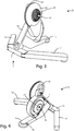
- a cycling simulation device D which includes a support frame 1, for the ground support of said device D, coupling members 2, for coupling said device D with a racing bicycle, road or mountain bike type, and said flywheel 3 covered by a cover casing.
- Said frame 1 comprises a central elongated arm 11 having two opposed ends, to which the ends of two lateral arms, in particular a first 12 and a second 13 arm, are rotatably coupled, which can assume a closure position, in which they are substantially arranged parallel, and an opening position, in which they are spaced or spaced from said central arm 11, so as to support the cycling simulation device 1.
- Said frame 1 comprises a main element 14 integral with said central arm 11, which is vertical with respect to said central arm 11.
- Said main element 14 is supported by a third arm 15, centrally positioned between said first 12 and second 13 arm.
- Said coupling members 2, supported by said frame 1, comprise a lower main shaft 21 and a secondary upper shaft 22 connected together with a belt 23, which is supported by a pulley 24.
- Said pulley 24 is integral with said secondary shaft 22 and simulates the rear wheel of a bicycle to be coupled.
- said device D comprises a sprocket 25 or cassette pack, which the chain of said bicycle is engaged with, rotatably coupled with said secondary shaft 22 by means of a free wheel so as to remain integral with said secondary shaft 22, when the user pedals in the driving direction and capable of decoupling from said secondary shaft 22 when the user pedals in the opposite direction.
- Said device D comprises said flywheel 3, which is rotatably coupled with said main element 14 by means of said main shaft 21, which will be described in detail hereinafter.
- said S system includes a torque sensor S c installed in said device D.
- said torque sensor S c is installed on said main shaft 21 to carry out a measurement of the torque that acts on said shaft 21 during the pedaling, a measure of the rotation speed of said shaft 21, and therefore of said flywheel 3, and a measure of the pedaling rate, as it will be described in detail in the following.
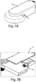
- said system S also includes an optical sensor S o installed on said device D, in particular on said third arm 15 in the part that faces towards said second arm 13, in order to detect the passage of the crank arm of the left pedal of the bicycle, and then of the left foot of the user, and send to said control logic unit U a signal about the cadence of the left foot pedal over time.
- said optical sensor S o can be housed on said third arm 15 in the part that faces towards said first arm 12, in order to detect the passage of the crank arm of the right bicycle pedal and therefore of the right foot of the user.
- said main shaft 21 comprises a first 211 and a second 212 circular bushing adjacent to each other and integral with said shaft 21.
- Said first 211 and second 212 bushing are provided on the circumference of respectively a first 211a, 211b, ..., 211n, and a second plurality of equally spaced teeth 211a, 211b,..., 211n.
- first 211a, 211b,..., 211n, and second plurality of teeth 211a, 211b, 211n are overlapped on one another.
- these may undergo a phase shift due to the mechanical twisting to which said shaft 21 is subjected to during the use of said device D due to the torque exerted on said shaft 21 during pedaling by the shaft user.
- Said torque sensor S c detects the phase shift between each tooth of said first plurality of teeth 211a, 211b,..., 211n and the corresponding tooth of said second plurality of teeth 211a, 211b,..., 211n and provides said control logic unit U the values of the torque during the time, as it will be described in detail below.
- Said system S comprises a remote device R as a smartphone or a tablet, provided with an application and a wireless interface, in particular a Bluetooth type interface, for the connection with said control logic unit U for controlling said flywheel 3, and in particular the motor that actuates the magnet holder bracket supporting the permanent magnet brake acting on the flywheel 3, according to the user-selected training program.
- a remote device R as a smartphone or a tablet
- a wireless interface in particular a Bluetooth type interface
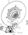
- figures 6A-6C show the abovementioned braking means 40, which, in the embodiment shown, comprise a magnet holder bracket 41, pivoted about a pivot 42, and first 43' and a second 43" pair of permanent magnets 43, housed within said magnet holder bracket 41, so that each permanent magnet 43 of said first pair of permanent magnets 43' is faced to a respective permanent magnet 43 of said second pair of permanent magnets 43", in such a way that the flywheel 3 can pass between the magnets 43 of said first 43' and said second 43" pairs of permanent magnets.
- Said magnet holder bracket 41 can assume an inactive position, in which the permanent magnets 43 of said first 43' and said second 43" pairs of permanent magnets are not overlapped over the flywheel 3, and active positions, in which said permanent magnets 43 of said first 43' and said second 43" pairs of permanent magnets are at least partially overlapped over the flywheel 3.
- Said braking means 40 also comprise a motor 44, preferably an electric motor 44, arranged for rotating a worm screw 45, and a nut screw 46, engaged with said worm screw 45.
- Said nut screw 46 being integral with, or fixed to said magnet holder bracket 41, in order to cause, when rotated, said magnet holder bracket 41 to pass from said inactive position to said active position.
- control logic unit U When the control logic unit U actuates the motor 44, the latter causes the rotation of the worm screw 45 according to a first rotation direction, so as to rotate the nut screw 46.
- the flywheel 3 is made of an appropriate metal material.
- the brake can be of electromagnetic type and in that case the adjustment is by adjusting the current flowing through the winding turns.
- Said remote device R allows the user to set the training he or she intends to perform on said device D and graphically display a representative training quality curve he or she is performing as shown in figure 12 , or a movable bar can be displayed on a series of colored squares, as shown in figure 13 .
- the types of training are mainly two: a constant power training and a constant slope training.
- the user sets a fixed power value P expressed in Watts in the training program included in the application of his remote device R.
- the user can also make manual adjustments to said predetermined paths, for example by setting a fixed power value.
- the user can select one out of a plurality of workouts stored in the memory of said remote device R, based on predetermined paths, such as a known race path, so as to simulate a real road pedal.
- the user can make manual changes to the preset path, for example, by changing the slope.
- the power P is given by the product between torque, or the brake resistance on said flywheel 3, and the rotational speed of said main shaft 21.
- said control logic unit U adjusts the braking force acting on said flywheel 3.
- said torque sensor S c detects, according to a known way, the phase shift between each tooth of said first plurality of teeth 211a, 211b,..., 211n and the corresponding tooth of said second plurality of teeth 211a, 211b,..., 211n, detecting the beam emitted by an infrared source 213 and passing through free space ⁇ , as shown in figure 9 .
- Said space ⁇ is the free space between two contiguous teeth of the first plurality of teeth 211a, 211b,..., 211n, which does not overlap with a tooth of the second plurality of teeth 211a, 211b,..., 211n.
- said torque sensor S c detects the amount of light passing through said space ⁇ , alternatively, it can detect the time that elapses between the passage of one space ⁇ and the passage of immediately following space ⁇ + 1.
- Said torque sensor sends these data to said control logic unit U, which generates a trend over the time of the torque acting on said main shaft 21, obtaining a substantially sinusoidal signal as shown in figure 10 .
- Said optical sensor S o instead detects the distance of the arm crank of the left pedal and sends to said control logic unit U a time pulse each time the crank arm, and then the user's foot, passes close to said optical sensor S o .
- Said control logic unit U processes these pulses and generates a pulse-time trend, obtaining a substantially triangular signal as shown in figure 11 .
- the trend of figure 11 shows a sequence of curves having a first rising section due to the detection of said optical sensor S o in the approaching of the left foot of the user and a part that decreases immediately to zero, due to the passage of the foot over said optical sensor S o .
- the control logic unit U performs a correlation between the sinusoidal curve and the triangular curve.
- the logic control unit U associates the next torque peak to the right foot.
- said logic control unit can cyclically solve the known Ambrosini equation that describes the motion of the bike in terms of the power delivered on the pedals as a function of parameters such as the weight of the user and of the bike, the road slope, the asphalt friction coefficient, the aerodynamic coefficient, the speed of the bike and the gravity acceleration.
- Said parameters are already stored in the application contained in said remote device R, while the user's weight value is set by the user at the moment the workout begins.
- said control logic unit U calculates the expected torque value on the rear wheel and then on said pulley 23, thereby activating the permanent magnets brake motor acting on said flywheel 3. If the pedaling speed is high, so that the torque and speed product remains constant, said control logic unit U increases the torque and then the resistance opposed by said flywheel 3 to the pedal, the opposite occurs in case of the pedaling speed is low.
- the user can select a workout based on a predetermined path on his remote device R, such as a known race path.
- control logic unit U determines the torque that has to act on said flywheel 3, based on the solution of the motion equation described above.
- said remote device R sends information to said system S, which consequently has to reduce the resistance value on said flywheel 3, thus driving remotely the motor that moves said permanent magnet brake, so as to move away from said flywheel 3, thus simulating a slope.
- said remote device R transmits the information to said system S, which has consequently to increase the resistance value on said flywheel 3, by remotely activating the motor that moves said permanent magnet brake, so as it to approach said flywheel 3, thus simulating a rise.
- said control logic unit U performs a continuous correlation over time between the sine curve and the triangular curve and sends to said remote device R the value of the torque peak generated during a pedal by the right foot, the minimum value of the torque generated during a pedal by the right foot, the torque peak value generated during a left foot pedal, the minimum value generated during a foot pedal from the left foot and the time intervals between the values A and B, B and C, C and D, and the following value A of the next pedal.
- said remote device R allows to display the graphical representations of figures 12 or 13 .
- the first part of the curve relates to the pedal with the left foot, while the second part of the curve relates to the pedal with the right foot and are overlapped on a reference line shown on said remote device R in green color.
- the bar will be positioned substantially in the center of the rectangles, otherwise it will be unbalanced to the right or to the left of the rectangles if, respectively, he employs more strength with the right or left foot.
- the improved control system allows for precise remote control of the resistance generated by a cycling simulation device using simple and economic tools.
Landscapes
- Health & Medical Sciences (AREA)
- General Health & Medical Sciences (AREA)
- Physical Education & Sports Medicine (AREA)
- Orthopedic Medicine & Surgery (AREA)
- Life Sciences & Earth Sciences (AREA)
- Biophysics (AREA)
- Physics & Mathematics (AREA)
- Electromagnetism (AREA)
- Engineering & Computer Science (AREA)
- Human Computer Interaction (AREA)
- Multimedia (AREA)
- Cardiology (AREA)
- Vascular Medicine (AREA)
- Force Measurement Appropriate To Specific Purposes (AREA)
- Testing And Monitoring For Control Systems (AREA)
- Selective Calling Equipment (AREA)
Claims (9)
- Fahrradsimulationsvorrichtung (D) der Art, die einen Stützrahmen (1) umfasst, an dem Kopplungselemente (25) zum Koppeln mit der Fahrradkette installiert sind, mit dem ein Benutzer ein Training durchführt, indem er auf die jeweiligen Pedale des Fahrrads wirkt, ein Schwungrad (3), das sich um eine Hauptwelle (21) dreht, die mit den Kopplungselementen (25) verbunden ist, Bremsmittel, die auf das Schwungrad (3) wirken, und eine Steuerlogikeinheit (U), die dazu in der Lage ist, bei Übertragung und Empfang mit einer entfernten Vorrichtung (R) zu verbinden, mit der ein Benutzer einen oder mehrere Trainingsparameter einstellen kann, wobei die Fahrradsimulationsvorrichtung (D) umfasst
einen Drehmomentsensor (Sc) zum Erkennen und Senden an die Steuerlogikeinheit (U) eines Signals als eine Funktion des Drehmoments, das auf die Hauptwelle (21) während der Drehung des Schwungrads (3) wirkt,
wobei die Steuerlogikeinheit (U) derart konfiguriert ist, dass sie die Vielzahl von Trainingsparametern, die von dem Benutzer aus der entfernten Vorrichtung (R) ausgewählt wurden, zu empfangen, und die Bremskraft, die von den Bremsmitteln (40) auf das Schwungrad (3) ausgeübt wird, als eine Funktion der Parameter, die von dem Benutzer eingestellt wurden, und des Signals, das sich auf das Drehmoment bezieht, das auf die Hauptwelle (21) wirkt, das von dem Drehmomentsensor (Sc) erkannt wird, einzustellen, wobei die Fahrradsimulationsvorrichtung (D) dadurch gekennzeichnet ist, dass
sie einen optischen Sensor (So) umfasst, der mit dem Stützrahmen (1) gekoppelt ist, um die Werte der Distanz zwischen mindestens einem von den zwei Pedalen des Fahrrads von dem optischen Sensor (So) selbst zu erkennen und ein Signal proportional zu den Distanzwerten an die Steuerlogikeinheit (U) zu senden, und
dadurch, dass die Steuerlogikeinheit (U) eine Korrelation zwischen dem Signal, das von dem Drehmomentsensor (Sc) empfangen wurde, und dem Signal, das von dem optischen Sensor (So) empfangen wurde, durchzuführen, um einen Wert des Drehmoments, das auf die Hauptwelle (22) wirkt, mindestens einem Fahrradpedal zuzuordnen. - Vorrichtung (D) nach dem vorstehenden Anspruch, wobei der Stützrahmen (1) von der Art ist, die einen zentralen länglichen Arm (11) umfasst, der an zwei gegenüberliegenden Enden bereitgestellt wird, an denen die Enden eines ersten (12) und eines zweiten (13) und eines dritten (15) Arms schwenkbar gekoppelt sind, wobei der zentrale Arm (11) zentral zwischen dem ersten (12) und zweiten (13) Arm positioniert ist, wobei optischer Sensor (So) an dem dritten Arm (15) in dem Abschnitt positioniert ist, der in Richtung des zweiten Arms (13) weist, zum Erkennen des Durchgangs des linken Pedals des Fahrrads.
- Vorrichtung (D) nach einem der vorstehenden Ansprüche, wobei der Stützrahmen (1) von der Art ist, die einen zentralen länglichen Arm (11) umfasst, der mit zwei gegenüberliegenden Enden bereitgestellt wird, an die die Enden eines ersten (12) und eines zweiten (13) und eines dritten (15) Arms schwenkbar gekoppelt sind, wobei der zentrale Arm (11) zentral zwischen dem ersten (12) und zweiten (13) Arm positioniert ist, wobei der optische Sensor (So) an dem dritten Arm (15) auf dem Abschnitt positioniert ist, der in Richtung des zweiten Arms (13) weist, zum Erkennen des Durchgangs des rechten Pedals des Fahrrades.
- Vorrichtung (D) nach einem der vorstehenden Ansprüche, wobei die Bremsmittel (40) umfassen
mindestens einen Permanentmagneten (43),
eine Magnethalterung (41), die den mindestens einen Permanentmagneten (43) aufnimmt, wobei die Magnethalterung (41) dazu in der Lage ist, eine inaktive Position einzunehmen, in der der mindestens eine Permanentmagnet (43) nicht das Schwungrad (3) überlappt, und eine aktive Position, in der der mindestens eine Permanentmagnet (43) zumindest teilweise das Schwungrad (3) überlappt, und
einen Motor (44), der mit der Steuerlogikeinheit (U) verbunden ist und von dieser gesteuert wird, wobei der Motor (44) angeordnet ist, die Magnethalterung (41) zu veranlassen, von der inaktiven Position zu einer aktiven Position und umgekehrt überzugehen. - Vorrichtung (D) nach dem vorstehenden Anspruch, wobei
die Magnethalterung (41) um einen Drehpunkt (42) schwenkbar ist, und
die Bremsmittel (40) umfassen
eine Madenschraube (45), die angeordnet ist, von dem Motor (43) gedreht zu werden, und
eine Schraube mit Mutter (45) in Eingriff mit der Madenschraube (44), wobei die Schraube mit Mutter (46) integral mit der Magnethalterung (41) oder an dieser fixiert ist,
so dass, wenn die Steuerlogikeinheit (U) den Motor (44) betätigt, der Motor (44) die Drehung der Madenschraube (45) nach einer ersten Drehrichtung veranlasst, so dass die Schraube mit Mutter (46) dreht und die Magnethalterung (41) um den Drehpunkt (42) dreht, so dass sich die überlappende Fläche des mindestens einen Permanentmagneten (43) vergrößert, und
wenn der Motor (44) die Madenschraube (45) in eine zweite Richtung dreht, die der ersten Drehrichtung entgegengesetzt ist, die Schraube mit Mutter (46) die Magnethalterung (41) aus der aktiven Position zu der inaktiven Position dreht. - Vorrichtung (D) nach einem der vorstehenden Ansprüche 4 oder 5, wobei die Bremsmittel (40) umfassen
ein erstes Paar (43') von Permanentmagneten (43) und
ein zweites Paar (43") von Permanentmagneten (43),
wobei das erste (43') und das zweite (43") Paar von Permanentmagneten (43) innerhalb der Magnethalterung (41) untergebracht ist, so dass jeder Permanentmagnet (43) des ersten Paares von Permanentmagneten (43') einem jeweiligen Permanentmagneten (43) des zweiten Paares von Permanentmagneten (43") zugewandt ist,
das Schwungrad (3) zwischen dem ersten (43') und dem zweiten (43") Paar von Permanentmagneten (43) verläuft. - Vorrichtung (D) nach einem der vorstehenden Ansprüche, wobei die Bremsmittel (40) elektromagnetischer Art sind, eine Spule und eine Kupplung umfassen, die von der Spule, die aus Wicklungswindungen besteht, betätigt werden, wobei die Einstellung der Bremsaktion durch Einstellen des Stroms, der durch die Wicklungswindungen fließt, eingestellt wird.
- Vorrichtung (D) nach einem der vorstehenden Ansprüche, wobei die entfernte Vorrichtung (R) eine voreingestellte grafische Repräsentation der Korrelation zeigt, die von der Logiksteuereinheit (U) des Signals, das von dem Drehmomentsensor (Sc) empfangen wird, und dem Signal, das von dem optischen Sensor (So) empfangen wird, durchgeführt wird.
- Verfahren zum Steuern einer Vorrichtung (D) nach einem der vorstehenden Ansprüche, die folgenden Schritte umfassend von:a. Bereitstellen einer entfernten Vorrichtung (R), die mit einer Speichereinheit ausgestattet ist, die konfiguriert ist, eine oder mehrere Parameter in Bezug auf eine Vielzahl von Trainings, die in der Speichereinheit gespeichert sind, die von einem Benutzer auswählbar sind, einzustellen;b. funktionsfähiges Verbinden der entfernten Vorrichtung (R) mit der Steuerlogikeinheit (U);c. Auswählen eines vordefinierten Trainingsprogramms, das in der Speichereinheit der entfernten Vorrichtung (R) gespeichert ist, entsprechend eines realen vorbestimmten Weges, der mit einer Vielzahl von festen oder durch den Benutzer manuell einstellbaren Parametern identifiziert wird, oder basierend auf Parametern, die von dem Benutzer eingestellt werden;d. Senden der Parameter in Bezug auf das ausgewählte vordefinierte Trainingsprogramm an die Steuerlogikeinheit (U); unde. Einstellen der Bremskraft, die von den Bremsmitteln (40) auf das Schwungrad (3) ausgeübt wird, als eine Funktion der Parameter in Bezug auf das ausgewählte vordefinierte Trainingsprogramm und des Signals in Bezug auf das Drehmoment, das auf die Hauptwelle (21) wirkt, das von dem Drehmomentsensor (Sc) erfasst wird.
Applications Claiming Priority (1)
| Application Number | Priority Date | Filing Date | Title |
|---|---|---|---|
| IT102016000068770A IT201600068770A1 (it) | 2016-07-01 | 2016-07-01 | Sistema di controllo perfezionato di un dispositivo di simulazione ciclistica. |
Publications (2)
| Publication Number | Publication Date |
|---|---|
| EP3263189A1 EP3263189A1 (de) | 2018-01-03 |
| EP3263189B1 true EP3263189B1 (de) | 2019-10-02 |
Family
ID=57796790
Family Applications (1)
| Application Number | Title | Priority Date | Filing Date |
|---|---|---|---|
| EP17177807.9A Active EP3263189B1 (de) | 2016-07-01 | 2017-06-26 | Verbessertes steuerungssystem einer radfahrsimulationsvorrichtung |
Country Status (3)
| Country | Link |
|---|---|
| US (1) | US10272295B2 (de) |
| EP (1) | EP3263189B1 (de) |
| IT (1) | IT201600068770A1 (de) |
Families Citing this family (12)
| Publication number | Priority date | Publication date | Assignee | Title |
|---|---|---|---|---|
| IT201600083062A1 (it) * | 2016-08-05 | 2018-02-05 | Technogym Spa | Apparecchiatura ginnica per simulazione ciclistica e relativo metodo di funzionamento. |
| IT201800007830A1 (it) * | 2018-08-03 | 2020-02-03 | Technogym Spa | Dispositivo di resistenza regolabile per biciclette e metodo di funzionamento. |
| US12263368B2 (en) * | 2018-08-03 | 2025-04-01 | Peloton Interactive, Inc. | Braking systems and methods for exercise equipment |
| US20220003618A1 (en) * | 2018-10-02 | 2022-01-06 | Truekinetix B.V. | Torque sensing system |
| TWM577747U (zh) * | 2018-11-13 | 2019-05-11 | 祺驊股份有限公司 | 具有可變磁阻之飛輪健身器 |
| US10888736B2 (en) | 2019-02-22 | 2021-01-12 | Technogym S.P.A. | Selectively adjustable resistance assemblies and methods of use for bicycles |
| US11079918B2 (en) | 2019-02-22 | 2021-08-03 | Technogym S.P.A. | Adaptive audio and video channels in a group exercise class |
| US11633647B2 (en) | 2019-02-22 | 2023-04-25 | Technogym S.P.A. | Selectively adjustable resistance assemblies and methods of use for exercise machines |
| US11040247B2 (en) | 2019-02-28 | 2021-06-22 | Technogym S.P.A. | Real-time and dynamically generated graphical user interfaces for competitive events and broadcast data |
| US11058912B1 (en) * | 2021-01-04 | 2021-07-13 | Brooke Dunefsky | Adaptive device utilizing neuroplasticity for the rehabilitation of stroke victims |
| EP4426446A4 (de) * | 2021-11-03 | 2025-10-08 | Goslo Llc | System und verfahren zur behebung der bewegung von menschlichen angetriebenen fahrzeugen |
| CN117804794B (zh) * | 2023-12-29 | 2024-10-18 | 无锡信贝科技发展有限公司 | 一种助力自行车的制动性能检测预警方法及系统 |
Citations (1)
| Publication number | Priority date | Publication date | Assignee | Title |
|---|---|---|---|---|
| WO2009051298A1 (en) * | 2007-10-16 | 2009-04-23 | Dasan Rnd Co., Ltd. | Treadmill with automatic speed control and control module of the same |
Family Cites Families (10)
| Publication number | Priority date | Publication date | Assignee | Title |
|---|---|---|---|---|
| US5616104A (en) * | 1995-08-10 | 1997-04-01 | The United States Of America As Represented By The Administrator Of The National Aeronautics And Space Administration | Human powered centrifuge |
| EP0925096B1 (de) * | 1996-07-02 | 2004-05-19 | Graber Products, Inc. | Elektronisches übungssystem |
| US20070281828A1 (en) * | 2000-03-21 | 2007-12-06 | Rice Michael J P | Games controllers |
| US7648446B2 (en) * | 2004-06-09 | 2010-01-19 | Unisen, Inc. | System and method for electronically controlling resistance of an exercise machine |
| EP1868695A4 (de) * | 2005-03-23 | 2008-07-30 | Saris Cycling Group Inc | Steuerung des widerstands in einem widerstandstrainingssystem über einen geschlossenen regelkreis |
| US20080207402A1 (en) * | 2006-06-28 | 2008-08-28 | Expresso Fitness Corporation | Closed-Loop Power Dissipation Control For Cardio-Fitness Equipment |
| US9067099B2 (en) * | 2011-03-15 | 2015-06-30 | David Beard | Apparatus, system, and method for generating power for exercise equipment |
| US9468794B2 (en) * | 2011-09-01 | 2016-10-18 | Icon Health & Fitness, Inc. | System and method for simulating environmental conditions on an exercise bicycle |
| US9999818B2 (en) * | 2012-08-27 | 2018-06-19 | Wahoo Fitness Llc | Bicycle trainer |
| DE102012019338A1 (de) * | 2012-10-02 | 2014-04-03 | Andreas Fischer | Stationäres Trainingsrad |
-
2016
- 2016-07-01 IT IT102016000068770A patent/IT201600068770A1/it unknown
-
2017
- 2017-06-26 EP EP17177807.9A patent/EP3263189B1/de active Active
- 2017-06-28 US US15/635,763 patent/US10272295B2/en active Active
Patent Citations (1)
| Publication number | Priority date | Publication date | Assignee | Title |
|---|---|---|---|---|
| WO2009051298A1 (en) * | 2007-10-16 | 2009-04-23 | Dasan Rnd Co., Ltd. | Treadmill with automatic speed control and control module of the same |
Also Published As
| Publication number | Publication date |
|---|---|
| EP3263189A1 (de) | 2018-01-03 |
| IT201600068770A1 (it) | 2018-01-01 |
| US10272295B2 (en) | 2019-04-30 |
| US20180001142A1 (en) | 2018-01-04 |
Similar Documents
| Publication | Publication Date | Title |
|---|---|---|
| US10272295B2 (en) | Control system of a cycling simulation device | |
| AU2008291668B2 (en) | Ergometric training device | |
| EP3156108B1 (de) | Übungsgerät | |
| TWI744450B (zh) | 具有功率測量設備的固定式運動機 | |
| ES2885831T3 (es) | Aparato de ejercicio ergométrico estacionario | |
| US7585258B2 (en) | Power sensing eddy current resistance unit for an exercise device | |
| CA2702640A1 (en) | Performance monitoring & display system for exercise bike | |
| KR20180066473A (ko) | 자전거 운동 기구의 동작 처리 방법 및 장치 | |
| US20230302326A1 (en) | Method of controlling a force and/or resistance generator of an exercise apparatus | |
| KR101863963B1 (ko) | 직립형 자전거 성능 검사장치 | |
| US12458828B2 (en) | Resistance apparatus and system for exercise equipment | |
| EP3215241B1 (de) | Übungsvorrichtung | |
| JPH0742432Y2 (ja) | 訓練用自転車 | |
| HK1143103B (en) | Ergometric training device | |
| TWM451151U (zh) | 具有心跳回饋控制功能之飛輪健身器 |
Legal Events
| Date | Code | Title | Description |
|---|---|---|---|
| PUAI | Public reference made under article 153(3) epc to a published international application that has entered the european phase |
Free format text: ORIGINAL CODE: 0009012 |
|
| STAA | Information on the status of an ep patent application or granted ep patent |
Free format text: STATUS: THE APPLICATION HAS BEEN PUBLISHED |
|
| AK | Designated contracting states |
Kind code of ref document: A1 Designated state(s): AL AT BE BG CH CY CZ DE DK EE ES FI FR GB GR HR HU IE IS IT LI LT LU LV MC MK MT NL NO PL PT RO RS SE SI SK SM TR |
|
| AX | Request for extension of the european patent |
Extension state: BA ME |
|
| STAA | Information on the status of an ep patent application or granted ep patent |
Free format text: STATUS: REQUEST FOR EXAMINATION WAS MADE |
|
| 17P | Request for examination filed |
Effective date: 20180627 |
|
| RBV | Designated contracting states (corrected) |
Designated state(s): AL AT BE BG CH CY CZ DE DK EE ES FI FR GB GR HR HU IE IS IT LI LT LU LV MC MK MT NL NO PL PT RO RS SE SI SK SM TR |
|
| REG | Reference to a national code |
Ref country code: DE Ref legal event code: R079 Ref document number: 602017007400 Country of ref document: DE Free format text: PREVIOUS MAIN CLASS: A63B0021005000 Ipc: G05D0017020000 |
|
| GRAP | Despatch of communication of intention to grant a patent |
Free format text: ORIGINAL CODE: EPIDOSNIGR1 |
|
| STAA | Information on the status of an ep patent application or granted ep patent |
Free format text: STATUS: GRANT OF PATENT IS INTENDED |
|
| RIC1 | Information provided on ipc code assigned before grant |
Ipc: A63B 21/00 20060101ALI20181031BHEP Ipc: A63B 21/22 20060101ALI20181031BHEP Ipc: A63B 24/00 20060101ALI20181031BHEP Ipc: A63B 21/005 20060101ALI20181031BHEP Ipc: G05D 17/02 20060101AFI20181031BHEP Ipc: A63B 22/06 20060101ALI20181031BHEP |
|
| INTG | Intention to grant announced |
Effective date: 20181203 |
|
| RIN1 | Information on inventor provided before grant (corrected) |
Inventor name: VIARANI, LUIGI Inventor name: CRISTOFORI, CLAUDIO Inventor name: LORUSSO, MARCO |
|
| GRAJ | Information related to disapproval of communication of intention to grant by the applicant or resumption of examination proceedings by the epo deleted |
Free format text: ORIGINAL CODE: EPIDOSDIGR1 |
|
| STAA | Information on the status of an ep patent application or granted ep patent |
Free format text: STATUS: REQUEST FOR EXAMINATION WAS MADE |
|
| INTC | Intention to grant announced (deleted) | ||
| GRAP | Despatch of communication of intention to grant a patent |
Free format text: ORIGINAL CODE: EPIDOSNIGR1 |
|
| STAA | Information on the status of an ep patent application or granted ep patent |
Free format text: STATUS: GRANT OF PATENT IS INTENDED |
|
| INTG | Intention to grant announced |
Effective date: 20190524 |
|
| GRAS | Grant fee paid |
Free format text: ORIGINAL CODE: EPIDOSNIGR3 |
|
| GRAA | (expected) grant |
Free format text: ORIGINAL CODE: 0009210 |
|
| STAA | Information on the status of an ep patent application or granted ep patent |
Free format text: STATUS: THE PATENT HAS BEEN GRANTED |
|
| AK | Designated contracting states |
Kind code of ref document: B1 Designated state(s): AL AT BE BG CH CY CZ DE DK EE ES FI FR GB GR HR HU IE IS IT LI LT LU LV MC MK MT NL NO PL PT RO RS SE SI SK SM TR |
|
| REG | Reference to a national code |
Ref country code: GB Ref legal event code: FG4D |
|
| REG | Reference to a national code |
Ref country code: CH Ref legal event code: EP Ref country code: AT Ref legal event code: REF Ref document number: 1186899 Country of ref document: AT Kind code of ref document: T Effective date: 20191015 |
|
| REG | Reference to a national code |
Ref country code: DE Ref legal event code: R096 Ref document number: 602017007400 Country of ref document: DE |
|
| REG | Reference to a national code |
Ref country code: IE Ref legal event code: FG4D |
|
| REG | Reference to a national code |
Ref country code: NL Ref legal event code: MP Effective date: 20191002 |
|
| REG | Reference to a national code |
Ref country code: LT Ref legal event code: MG4D |
|
| REG | Reference to a national code |
Ref country code: AT Ref legal event code: MK05 Ref document number: 1186899 Country of ref document: AT Kind code of ref document: T Effective date: 20191002 |
|
| PG25 | Lapsed in a contracting state [announced via postgrant information from national office to epo] |
Ref country code: NL Free format text: LAPSE BECAUSE OF FAILURE TO SUBMIT A TRANSLATION OF THE DESCRIPTION OR TO PAY THE FEE WITHIN THE PRESCRIBED TIME-LIMIT Effective date: 20191002 Ref country code: SE Free format text: LAPSE BECAUSE OF FAILURE TO SUBMIT A TRANSLATION OF THE DESCRIPTION OR TO PAY THE FEE WITHIN THE PRESCRIBED TIME-LIMIT Effective date: 20191002 Ref country code: AT Free format text: LAPSE BECAUSE OF FAILURE TO SUBMIT A TRANSLATION OF THE DESCRIPTION OR TO PAY THE FEE WITHIN THE PRESCRIBED TIME-LIMIT Effective date: 20191002 Ref country code: PL Free format text: LAPSE BECAUSE OF FAILURE TO SUBMIT A TRANSLATION OF THE DESCRIPTION OR TO PAY THE FEE WITHIN THE PRESCRIBED TIME-LIMIT Effective date: 20191002 Ref country code: LT Free format text: LAPSE BECAUSE OF FAILURE TO SUBMIT A TRANSLATION OF THE DESCRIPTION OR TO PAY THE FEE WITHIN THE PRESCRIBED TIME-LIMIT Effective date: 20191002 Ref country code: ES Free format text: LAPSE BECAUSE OF FAILURE TO SUBMIT A TRANSLATION OF THE DESCRIPTION OR TO PAY THE FEE WITHIN THE PRESCRIBED TIME-LIMIT Effective date: 20191002 Ref country code: PT Free format text: LAPSE BECAUSE OF FAILURE TO SUBMIT A TRANSLATION OF THE DESCRIPTION OR TO PAY THE FEE WITHIN THE PRESCRIBED TIME-LIMIT Effective date: 20200203 Ref country code: FI Free format text: LAPSE BECAUSE OF FAILURE TO SUBMIT A TRANSLATION OF THE DESCRIPTION OR TO PAY THE FEE WITHIN THE PRESCRIBED TIME-LIMIT Effective date: 20191002 Ref country code: BG Free format text: LAPSE BECAUSE OF FAILURE TO SUBMIT A TRANSLATION OF THE DESCRIPTION OR TO PAY THE FEE WITHIN THE PRESCRIBED TIME-LIMIT Effective date: 20200102 Ref country code: NO Free format text: LAPSE BECAUSE OF FAILURE TO SUBMIT A TRANSLATION OF THE DESCRIPTION OR TO PAY THE FEE WITHIN THE PRESCRIBED TIME-LIMIT Effective date: 20200102 Ref country code: GR Free format text: LAPSE BECAUSE OF FAILURE TO SUBMIT A TRANSLATION OF THE DESCRIPTION OR TO PAY THE FEE WITHIN THE PRESCRIBED TIME-LIMIT Effective date: 20200103 Ref country code: LV Free format text: LAPSE BECAUSE OF FAILURE TO SUBMIT A TRANSLATION OF THE DESCRIPTION OR TO PAY THE FEE WITHIN THE PRESCRIBED TIME-LIMIT Effective date: 20191002 |
|
| PG25 | Lapsed in a contracting state [announced via postgrant information from national office to epo] |
Ref country code: RS Free format text: LAPSE BECAUSE OF FAILURE TO SUBMIT A TRANSLATION OF THE DESCRIPTION OR TO PAY THE FEE WITHIN THE PRESCRIBED TIME-LIMIT Effective date: 20191002 Ref country code: HR Free format text: LAPSE BECAUSE OF FAILURE TO SUBMIT A TRANSLATION OF THE DESCRIPTION OR TO PAY THE FEE WITHIN THE PRESCRIBED TIME-LIMIT Effective date: 20191002 Ref country code: CZ Free format text: LAPSE BECAUSE OF FAILURE TO SUBMIT A TRANSLATION OF THE DESCRIPTION OR TO PAY THE FEE WITHIN THE PRESCRIBED TIME-LIMIT Effective date: 20191002 Ref country code: IS Free format text: LAPSE BECAUSE OF FAILURE TO SUBMIT A TRANSLATION OF THE DESCRIPTION OR TO PAY THE FEE WITHIN THE PRESCRIBED TIME-LIMIT Effective date: 20200224 |
|
| PG25 | Lapsed in a contracting state [announced via postgrant information from national office to epo] |
Ref country code: AL Free format text: LAPSE BECAUSE OF FAILURE TO SUBMIT A TRANSLATION OF THE DESCRIPTION OR TO PAY THE FEE WITHIN THE PRESCRIBED TIME-LIMIT Effective date: 20191002 |
|
| REG | Reference to a national code |
Ref country code: DE Ref legal event code: R097 Ref document number: 602017007400 Country of ref document: DE |
|
| PG2D | Information on lapse in contracting state deleted |
Ref country code: IS |
|
| PG25 | Lapsed in a contracting state [announced via postgrant information from national office to epo] |
Ref country code: RO Free format text: LAPSE BECAUSE OF FAILURE TO SUBMIT A TRANSLATION OF THE DESCRIPTION OR TO PAY THE FEE WITHIN THE PRESCRIBED TIME-LIMIT Effective date: 20191002 Ref country code: DK Free format text: LAPSE BECAUSE OF FAILURE TO SUBMIT A TRANSLATION OF THE DESCRIPTION OR TO PAY THE FEE WITHIN THE PRESCRIBED TIME-LIMIT Effective date: 20191002 Ref country code: EE Free format text: LAPSE BECAUSE OF FAILURE TO SUBMIT A TRANSLATION OF THE DESCRIPTION OR TO PAY THE FEE WITHIN THE PRESCRIBED TIME-LIMIT Effective date: 20191002 Ref country code: IS Free format text: LAPSE BECAUSE OF FAILURE TO SUBMIT A TRANSLATION OF THE DESCRIPTION OR TO PAY THE FEE WITHIN THE PRESCRIBED TIME-LIMIT Effective date: 20200202 |
|
| PLBE | No opposition filed within time limit |
Free format text: ORIGINAL CODE: 0009261 |
|
| STAA | Information on the status of an ep patent application or granted ep patent |
Free format text: STATUS: NO OPPOSITION FILED WITHIN TIME LIMIT |
|
| PG25 | Lapsed in a contracting state [announced via postgrant information from national office to epo] |
Ref country code: SK Free format text: LAPSE BECAUSE OF FAILURE TO SUBMIT A TRANSLATION OF THE DESCRIPTION OR TO PAY THE FEE WITHIN THE PRESCRIBED TIME-LIMIT Effective date: 20191002 Ref country code: SM Free format text: LAPSE BECAUSE OF FAILURE TO SUBMIT A TRANSLATION OF THE DESCRIPTION OR TO PAY THE FEE WITHIN THE PRESCRIBED TIME-LIMIT Effective date: 20191002 |
|
| 26N | No opposition filed |
Effective date: 20200703 |
|
| PG25 | Lapsed in a contracting state [announced via postgrant information from national office to epo] |
Ref country code: SI Free format text: LAPSE BECAUSE OF FAILURE TO SUBMIT A TRANSLATION OF THE DESCRIPTION OR TO PAY THE FEE WITHIN THE PRESCRIBED TIME-LIMIT Effective date: 20191002 |
|
| PG25 | Lapsed in a contracting state [announced via postgrant information from national office to epo] |
Ref country code: MC Free format text: LAPSE BECAUSE OF FAILURE TO SUBMIT A TRANSLATION OF THE DESCRIPTION OR TO PAY THE FEE WITHIN THE PRESCRIBED TIME-LIMIT Effective date: 20191002 |
|
| REG | Reference to a national code |
Ref country code: CH Ref legal event code: PL |
|
| PG25 | Lapsed in a contracting state [announced via postgrant information from national office to epo] |
Ref country code: LU Free format text: LAPSE BECAUSE OF NON-PAYMENT OF DUE FEES Effective date: 20200626 |
|
| REG | Reference to a national code |
Ref country code: BE Ref legal event code: MM Effective date: 20200630 |
|
| PG25 | Lapsed in a contracting state [announced via postgrant information from national office to epo] |
Ref country code: LI Free format text: LAPSE BECAUSE OF NON-PAYMENT OF DUE FEES Effective date: 20200630 Ref country code: CH Free format text: LAPSE BECAUSE OF NON-PAYMENT OF DUE FEES Effective date: 20200630 Ref country code: FR Free format text: LAPSE BECAUSE OF NON-PAYMENT OF DUE FEES Effective date: 20200630 Ref country code: IE Free format text: LAPSE BECAUSE OF NON-PAYMENT OF DUE FEES Effective date: 20200626 |
|
| PG25 | Lapsed in a contracting state [announced via postgrant information from national office to epo] |
Ref country code: BE Free format text: LAPSE BECAUSE OF NON-PAYMENT OF DUE FEES Effective date: 20200630 |
|
| PG25 | Lapsed in a contracting state [announced via postgrant information from national office to epo] |
Ref country code: TR Free format text: LAPSE BECAUSE OF FAILURE TO SUBMIT A TRANSLATION OF THE DESCRIPTION OR TO PAY THE FEE WITHIN THE PRESCRIBED TIME-LIMIT Effective date: 20191002 Ref country code: MT Free format text: LAPSE BECAUSE OF FAILURE TO SUBMIT A TRANSLATION OF THE DESCRIPTION OR TO PAY THE FEE WITHIN THE PRESCRIBED TIME-LIMIT Effective date: 20191002 Ref country code: CY Free format text: LAPSE BECAUSE OF FAILURE TO SUBMIT A TRANSLATION OF THE DESCRIPTION OR TO PAY THE FEE WITHIN THE PRESCRIBED TIME-LIMIT Effective date: 20191002 |
|
| PG25 | Lapsed in a contracting state [announced via postgrant information from national office to epo] |
Ref country code: MK Free format text: LAPSE BECAUSE OF FAILURE TO SUBMIT A TRANSLATION OF THE DESCRIPTION OR TO PAY THE FEE WITHIN THE PRESCRIBED TIME-LIMIT Effective date: 20191002 |
|
| P01 | Opt-out of the competence of the unified patent court (upc) registered |
Effective date: 20230511 |
|
| PGFP | Annual fee paid to national office [announced via postgrant information from national office to epo] |
Ref country code: DE Payment date: 20250626 Year of fee payment: 9 |
|
| PGFP | Annual fee paid to national office [announced via postgrant information from national office to epo] |
Ref country code: GB Payment date: 20250617 Year of fee payment: 9 |
|
| PGFP | Annual fee paid to national office [announced via postgrant information from national office to epo] |
Ref country code: IT Payment date: 20250623 Year of fee payment: 9 |