EP3262222B1 - Guide device for a rapier in a gripper weaving machine - Google Patents
Guide device for a rapier in a gripper weaving machine Download PDFInfo
- Publication number
- EP3262222B1 EP3262222B1 EP16703803.3A EP16703803A EP3262222B1 EP 3262222 B1 EP3262222 B1 EP 3262222B1 EP 16703803 A EP16703803 A EP 16703803A EP 3262222 B1 EP3262222 B1 EP 3262222B1
- Authority
- EP
- European Patent Office
- Prior art keywords
- guide device
- rapier
- drive wheel
- weaving machine
- guide
- Prior art date
- Legal status (The legal status is an assumption and is not a legal conclusion. Google has not performed a legal analysis and makes no representation as to the accuracy of the status listed.)
- Active
Links
- 238000009941 weaving Methods 0.000 title claims description 52
- 238000001816 cooling Methods 0.000 claims description 37
- 239000012809 cooling fluid Substances 0.000 claims description 30
- 230000007704 transition Effects 0.000 claims description 20
- 238000000034 method Methods 0.000 claims description 11
- 239000010687 lubricating oil Substances 0.000 description 5
- 230000001050 lubricating effect Effects 0.000 description 3
- 239000003921 oil Substances 0.000 description 3
- 230000007850 degeneration Effects 0.000 description 2
- 238000005461 lubrication Methods 0.000 description 2
- 239000004020 conductor Substances 0.000 description 1
- 230000001419 dependent effect Effects 0.000 description 1
- 239000000428 dust Substances 0.000 description 1
- 230000020169 heat generation Effects 0.000 description 1
- 239000000463 material Substances 0.000 description 1
- XLYOFNOQVPJJNP-UHFFFAOYSA-N water Substances O XLYOFNOQVPJJNP-UHFFFAOYSA-N 0.000 description 1
Images

Classifications
-
- D—TEXTILES; PAPER
- D03—WEAVING
- D03D—WOVEN FABRICS; METHODS OF WEAVING; LOOMS
- D03D47/00—Looms in which bulk supply of weft does not pass through shed, e.g. shuttleless looms, gripper shuttle looms, dummy shuttle looms
- D03D47/27—Drive or guide mechanisms for weft inserting
- D03D47/275—Drive mechanisms
-
- D—TEXTILES; PAPER
- D03—WEAVING
- D03D—WOVEN FABRICS; METHODS OF WEAVING; LOOMS
- D03D47/00—Looms in which bulk supply of weft does not pass through shed, e.g. shuttleless looms, gripper shuttle looms, dummy shuttle looms
- D03D47/27—Drive or guide mechanisms for weft inserting
- D03D47/277—Guide mechanisms
-
- D—TEXTILES; PAPER
- D03—WEAVING
- D03J—AUXILIARY WEAVING APPARATUS; WEAVERS' TOOLS; SHUTTLES
- D03J1/00—Auxiliary apparatus combined with or associated with looms
- D03J1/008—Cooling systems
Definitions
- the invention relates to a guide device for a rapier in a gripper weaving machine, a gripper weaving machine with such a guide device and a method for cooling such a guide device.
- rapier weaving machines In prior art gripper weaving machines, also referred to as rapier weaving machines, a gripper is attached at the front end of a rapier for moving the gripper through a shed.
- the rapier is driven by a drive wheel arranged next to the shed.
- the rapier is kept into contact with the drive wheel by guide blocks.
- the rapier is guided between the shed and the drive wheel by straight stationary guides from and to the shed.
- the rapier is guided between the drive wheel and the lower side of the gripper weaving machine by a guide device from and to the lower side of the gripper weaving machine.
- the guide device guides the rear end of the rapier, this is the end of the rapier located opposite to the front end of the rapier at which the gripper is attached.
- Such guide devices can be designed in several shapes, for example a circular guide device as described in US 4,060,104 , a straight guide device as described in EP 0 126 497 B1 or GB 1396492 or a curved guide device as described in EP 0 412 453 B1 .
- the rapier is flexible allowing for guiding the rapier around the drive wheel and along the guide device.
- the changes in direction of the rapier by means of the guide devices have the disadvantage that a friction arises between the rapier and the guide device whereby a relatively large amount of heat is generated, which is particularly disadvantageous in wide and fast gripper weaving machines.
- BE 1000506 A4 discloses an arrangement comprising a first guide device arranged at an entry and a second guide device arranged at an exit of a drive wheel, wherein the first and second guide device are provided with cooling fins, and an airstream can be directed towards the cooling fins.
- CN 2161626 Y also shows guide devices arranged at an entry and an exit of a drive wheel.
- a guide device for guiding a rapier in a gripper weaving machine wherein in use the guide device is arranged adjacent to a drive wheel for driving the rapier at a side opposite to the shed in order to guide the rapier between the drive wheel and a lower side of the gripper weaving machine, wherein the guide device comprises a first straight part that in use is arranged adjacent to the drive wheel and comprises a second straight part that in use is arranged farther away from the drive wheel at an angle to the first straight part, in particular arranged more adjacent to the lower side of the gripper weaving machine, wherein the first straight part and the second straight part are connected to each other via a curved transition section, wherein the guide device comprises a cooling device in order to cool the guide device at least the area of the curved transition section, and wherein the guide device is provided with at least one channel for the cooling fluid running near a guiding surface for guiding the rapier.
- the invention offers the advantage that during weaving the operating temperature of the guide device can be limited by a forced cooling of the guide device. Also the friction between the rapier and the guide device can be limited by making use of a guide device with straight parts which also results in a lower operating temperature. In this case the friction and the associated heat generation is more locally at the height of the transition section, however, this heat can be removed with high efficiency by the cooling.
- the forced cooling can be carried out both during the operation of the gripper weaving machine and during a stop of the gripper weaving machine. Due to the limited temperature of the guide device, the temperature of the flexible rapier guided by the guide device can also be limited.
- the cooling of the guide device Due to the cooling of the guide device, heat generated by friction with the rapier can be removed, this means both local rises of temperature as overall rises of temperature are to be limited.
- the cooling of the guide device, and thus also the cooling of the rapier is advantageous in order to limit wear of the rapier and wear of the guide device. This is also advantageous in order to limit degeneration of the rapier, so that the material properties of the rapier can be maintained optimal. This is advantageous because wear and degeneration of the rapier occur faster at a high operating temperature of the rapier.
- the guide device also functions as a protection for the rapier for oil or dust, so that the rapier can be guided under the gripper weaving machine.
- the guiding surface is cooled, where most heat is generated by friction with the rapier.
- the guide device is formed by a first elongated profile and a second elongated profile which form together a tubular guide for the rapier.
- a tubular guide device allows to completely enclose and to completely catch the rapier in the guide device.
- the guide device can enclose the rapier not completely or only almost completely.
- the guide device comprises a first elongated profile with a first guiding surface that cooperates with an outer surface of the curved rapier and which is provided with at least one channel for the cooling fluid, this means one or more channels for the cooling fluid which are part of the cooling device.
- Such cooling allows to remove the heat that is locally generated by friction between the rapier and the first guiding surface of the guide device near the first guiding surface where a relatively large amount of heat is generated. As the friction is the largest at the height of the outer surface of the rapier, most heat is also generated by locally guiding the outer surface of the rapier against the first guiding surface of the first profile.
- the first profile is made of good conductive material such that sufficient heat can be removed, so that the guide device together with the rapier warm-up relatively slightly.
- the at least one channel for the cooling fluid is provided near the first guiding surface for the rapier in order to be able to remove sufficient heat.
- the guide device comprises a second elongated profile with a second guiding surface that cooperates with an inner surface of the curved rapier and which is attached to the first elongated profile.
- the second elongated profile can be provided with at least one channel for the cooling fluid.
- the first elongated profile and the second elongated profile are made in one piece that is provided with at least one channel for the cooling fluid.
- the at least one channel for the cooling fluid extends over almost the full length of the guide device in order to cool the guide device.
- the first straight part of the guide device in use is arranged tangentially with respect to the drive wheel in order to guide the rapier from and to the drive wheel.
- the rapier preferably is bent around the drive wheel.
- the cooling fluid is oil, for example lubricating oil for the gripper weaving machine.
- Lubricating oil is available in each gripper weaving machine and each gripper weaving machine comprises a system allowing to circulate the lubricating oil.
- the cooling fluid may also consist of water, compressed air or another cooling fluid, such as humidified compressed air.
- the guide device can be provided for example with cooling fins along which the air is guided.
- the guide device can be cooled by a cooling device which cooperates with a contact surface of the guide device, for example a profile provided with cooling channels which is arranged against a contact surface of the guide device.
- a gripper weaving machine comprising a rapier, a drive wheel for driving a rapier, wherein in use a gripper is arranged at the front end of the rapier, wherein the gripper weaving machine comprises a guide device according to the invention with a first straight part and a second straight part connected to each other via a curved transition section in order to guide the rapier between the drive wheel and a lower side of the gripper weaving machine.
- the guide device comprises a first straight part, a second straight part and a curved transition section that connects the first straight part and the second straight part.
- the rapier is bent around the drive wheel and the guide device is arranged adjacent to the drive wheel opposite to the front end of the rapier at which the gripper is arranged.
- the guide device comprises a first elongated profile for guiding an outer surface of the rapier, which first elongated profile is provided with at least one channel for the cooling fluid.
- the guide device can also comprise a second elongated profile attached to the first elongated profile.
- the first straight part of the guide device is arranged tangentially with respect to the drive wheel in order to guide the rapier from and to the drive wheel.
- the rapier is bent around the drive wheel.
- the guide device is arranged between the drive wheel and a horizontally arranged guide for the rapier.
- the horizontally arranged guide allows to further guide the rear end of the rapier in case of wide weaving machines.
- the horizontally arranged guide also allows to further guide the rapier below the shed.
- a method for cooling a guide device for a rapier in a gripper weaving machine comprising cooling the guide device according to the invention.
- the method for cooling comprises guiding a cooling fluid for cooling a guiding surface for the rapier at least in the area of the curved transition section of the guide device.
- the method for cooling makes use of oil as cooling fluid, in particular lubricating oil of the gripper weaving machine.
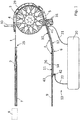
- Figure 1 is a schematic view of a part of a gripper weaving machine with a rapier 1 at which in use a gripper 2 is attached at the front end 25 of the rapier 1.
- the gripper 2 is either a so-called bringer gripper, or a so-called receiver gripper.
- a drive wheel 3 is illustrated for driving the rapier 1 to and fro, that is driven by driving means (not illustrated).
- the rapier 1 is kept into contact with the drive wheel 3 by means of guide blocks 4 and 5 assigned to the drive wheel 3.
- the rapier 1 is flexible in order to allow the rapier 1 to bend around the drive wheel 3.
- the rapier 1 is guided in a guide device 6 according to the invention in order to guide the rapier 1 to the lower side of the gripper weaving machine and/or below the shed 8 (indicated schematically).
- the guide device 6 guides the rear end 26 of a rapier 1, this is the end of the rapier 1 located opposite to the front end 25 at which the gripper 2 is attached.
- another stationary guide 7 for the rapier 1 is provided between the drive wheel 3 and the shed 8 to guide the rapier 1 from and to the shed 8.
- the stationary guide 7 and the guide device 6 are attached to a frame (not shown) of the weaving machine.
- a horizontally arranged guide 9 for the rapier 1 is provided that is arranged such that the guide device 6 is arranged between the drive wheel 3 and the horizontally arranged guide 9.
- the guide 9 is connected via a connecting element 43 to the guide device 6.
- the guide device 6 is arranged with respect to the drive wheel 3 at the side of the drive wheel 3 that is opposite to the side of the drive wheel 3 at which the gripper 2 is arranged.
- the rapier 1 can also cooperate with a guide 29 arranged opposite to the drive wheel 3.
- the rapier 1 can also cooperate with a lubrication pin 30 and/or a lubrication pin 31 in order to lubricate the rapier 1.
- the guide device 6 in use is arranged at the side of the drive wheel 3 opposite to the shed 8 in order to guide the rapier 1 from the drive wheel 3 to the lower side of the gripper weaving machine.
- the guide device 6 in use is arranged tangentially with respect to the drive wheel 3 in order to further guide the rapier 1 from the drive wheel 3.
- the guide device 6 comprises a first straight part 10 that in use is arranged adjacent to the drive wheel 3.
- the first straight part 10 of the guide device 6 is arranged tangentially with respect to the drive wheel 3 in order to further guide the rapier 1 from the drive wheel 3.
- the guide device 6 also comprises a second straight part 11 that in use is arranged farther away from the drive wheel 3 and adjacent to the lower side of the gripper weaving machine.
- the first straight part 10 and the second straight part 11 form an angle A with each other and are connected to each other via a curved transition section 12.
- the guide device 6 according to the invention comprises at least one cooling device 13 intended to cool the guide device 6 at least in the area of the curved transition section 12.
- the cooling near the curved transition section 12 allows for cooling in an area where most heat is generated by friction between the rapier 1 and the guide device 6, because at the height of the curved transition section 12 the rapier 1 pushes most on the guide device 6. Due to the curved transition section 12 the guide device 6 is bent allowing to guide the rapier 1 along the guide device 6 to the lower side of the gripper weaving machine.
- the guide device 6 comprises a cooling device 13 which is formed by a channel 14 for a cooling fluid arranged in the guide device 6.
- the guide device 6 comprises a first elongated bended profile 15 in which the channel 14 for the cooling fluid is provided.
- the first elongated bended profile 15 cooperates with the outer surface 16 of the rapier 1, this is the surface of the curved rapier 1 located at the outer side of the shaped arch in the rapier 1 and that can make contact with the profile 15 of the guide device 6 as can be seen in figure 1 .
- the guide device 6 comprises a second elongated bended profile 17 attached to the first profile 15 and cooperating with the inner surface 18 of the rapier 1, this is the surface of the curved rapier 1 located at the inner side of the shaped arch of the rapier 1 and that can make contact with the profile 17 of the guide device 6 as can be seen in figures 1 and 4 .
- the first profile 15 and the second profile 17 are connected relative to one another by connections 19 and form together a tubular guide device 6 in which the rapier 1 can be guided with play.
- the shape of the profile 15 and of the associated profile 17 is such that the profiles 15 and 17 form together the first straight part 10, the second straight part 11 and the curved transition section 12.
- the cooling device 13 with the channel 14 cooperates with the lubricating system 20 of the gripper weaving machine, so that for cooling the guide device 6 use is made of lubricating oil of the gripper weaving machine as the cooling fluid.
- the lubricating system 20 is connected via lines 21 and 22 with the channel 14.
- the channel 14 for the cooling fluid extends over almost the full length of the guide device 6 in order to cool the guide device 6, more in particular extends between the connector 41 for the line 21 and the connector 42 for the line 22.
- the rapier 1 is cooled.
- the profile 15 is provided with a guiding surface 27 for the outer surface 16 of the rapier 1 and the profile 17 is provided with a guiding surface 28 for the inner surface 18 of the rapier 1.
- the guide device 6 is provided with a channel 14 for the cooling fluid running near the guiding surface 27.
- the guide device 6 is formed by the first profile 15 and the second profile 17 which form together a tubular guide for the rapier 1.
- the sides of the rapier 1 are hereby guided by guiding elements 32 and 33 provided at the profile 15 and for example are designed in the shape of a collar.
- the guide device 6 with the first straight part 10, the second straight part 11 and the curved transition section 12, that connects the first straight part 10 and the second straight part 11, is cooled by guiding a cooling fluid through the channel 14 located near the guiding surface 27 for the rapier 1.
- this cooling can take place over almost the full length of the guide device 6.
- the heat is mainly generated in the area of the curved transition section 12, it may be sufficient to cool the guide device 6 in the area of the curved transition section 12.
- FIG. 5 is a variant of figure 4 wherein the cooling device 13 comprises two channels 14, 24 for the cooling fluid associated with the first bended profile 15.
- the cooling device 13 also comprises a channel 23 for the cooling fluid associated with the second bended profile 17.
- the sides of the rapier 1 are guided by guiding elements 34 and 35 provided at the second profile 17.
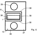
- Figure 6 is a variant of figure 4 wherein the guide device 6 is formed by a bended tubular profile 36.
- the cooling device 13 is formed by a housing 37 cooperating with at least one contact surface 38 of the guide device 6 formed by the profile 36.
- the housing 37 is provided with two cooling channels 39, that for example are provided with cooling fluid via the lubricating system 20 (illustrated in figure 1 ) of the gripper weaving machine.
- the housing 37 is arranged against the contact surfaces 38 of the profile 36 of the guide device 6 in order to cool the guide device 6.
- the gripper weaving machine comprises a bringer gripper and a receiver gripper
- a drive wheel 3 for a rapier 1 and associated guide device 6 according to the invention can be arranged for the rapier 1.
- the guide device, the gripper weaving machine and the method according to the invention are not limited to the embodiments described by way of example and shown in the drawings. Variants and combinations of the described and shown embodiments that fall under the claims are also possible.
Landscapes
- Engineering & Computer Science (AREA)
- Textile Engineering (AREA)
- Looms (AREA)
Description
- The invention relates to a guide device for a rapier in a gripper weaving machine, a gripper weaving machine with such a guide device and a method for cooling such a guide device.
- In prior art gripper weaving machines, also referred to as rapier weaving machines, a gripper is attached at the front end of a rapier for moving the gripper through a shed. The rapier is driven by a drive wheel arranged next to the shed. The rapier is kept into contact with the drive wheel by guide blocks. The rapier is guided between the shed and the drive wheel by straight stationary guides from and to the shed. The rapier is guided between the drive wheel and the lower side of the gripper weaving machine by a guide device from and to the lower side of the gripper weaving machine. In this case the guide device guides the rear end of the rapier, this is the end of the rapier located opposite to the front end of the rapier at which the gripper is attached.
- Such guide devices can be designed in several shapes, for example a circular guide device as described in
US 4,060,104 , a straight guide device as described inEP 0 126 497 B1 orGB 1396492 EP 0 412 453 B1 . In this case the rapier is flexible allowing for guiding the rapier around the drive wheel and along the guide device. The changes in direction of the rapier by means of the guide devices have the disadvantage that a friction arises between the rapier and the guide device whereby a relatively large amount of heat is generated, which is particularly disadvantageous in wide and fast gripper weaving machines.BE 1000506 A4 CN 2161626 Y also shows guide devices arranged at an entry and an exit of a drive wheel. - It is an object of the invention to provide a guide device which can be applied in wide and/or fast weaving machines. It is further an object of the invention to provide a gripper weaving machine with such a guide device. It is further an object of the invention to provide a method for cooling such a guide device.
- These objects are solved by a guide device with the features of
claim 1, a gripper weaving machine with the features of claim 8, a method with the features ofclaim 13, and by the dependent claims. - According to a first aspect of the invention a guide device for guiding a rapier in a gripper weaving machine is provided, wherein in use the guide device is arranged adjacent to a drive wheel for driving the rapier at a side opposite to the shed in order to guide the rapier between the drive wheel and a lower side of the gripper weaving machine, wherein the guide device comprises a first straight part that in use is arranged adjacent to the drive wheel and comprises a second straight part that in use is arranged farther away from the drive wheel at an angle to the first straight part, in particular arranged more adjacent to the lower side of the gripper weaving machine, wherein the first straight part and the second straight part are connected to each other via a curved transition section, wherein the guide device comprises a cooling device in order to cool the guide device at least the area of the curved transition section, and wherein the guide device is provided with at least one channel for the cooling fluid running near a guiding surface for guiding the rapier.
- The invention offers the advantage that during weaving the operating temperature of the guide device can be limited by a forced cooling of the guide device. Also the friction between the rapier and the guide device can be limited by making use of a guide device with straight parts which also results in a lower operating temperature. In this case the friction and the associated heat generation is more locally at the height of the transition section, however, this heat can be removed with high efficiency by the cooling. The forced cooling can be carried out both during the operation of the gripper weaving machine and during a stop of the gripper weaving machine. Due to the limited temperature of the guide device, the temperature of the flexible rapier guided by the guide device can also be limited. Due to the cooling of the guide device, heat generated by friction with the rapier can be removed, this means both local rises of temperature as overall rises of temperature are to be limited. The cooling of the guide device, and thus also the cooling of the rapier, is advantageous in order to limit wear of the rapier and wear of the guide device. This is also advantageous in order to limit degeneration of the rapier, so that the material properties of the rapier can be maintained optimal. This is advantageous because wear and degeneration of the rapier occur faster at a high operating temperature of the rapier. The guide device also functions as a protection for the rapier for oil or dust, so that the rapier can be guided under the gripper weaving machine.
- Preferably, the guiding surface is cooled, where most heat is generated by friction with the rapier.
- According to an embodiment the guide device is formed by a first elongated profile and a second elongated profile which form together a tubular guide for the rapier. A tubular guide device allows to completely enclose and to completely catch the rapier in the guide device. According to a variant the guide device can enclose the rapier not completely or only almost completely.
- According to an embodiment the guide device comprises a first elongated profile with a first guiding surface that cooperates with an outer surface of the curved rapier and which is provided with at least one channel for the cooling fluid, this means one or more channels for the cooling fluid which are part of the cooling device. Such cooling allows to remove the heat that is locally generated by friction between the rapier and the first guiding surface of the guide device near the first guiding surface where a relatively large amount of heat is generated. As the friction is the largest at the height of the outer surface of the rapier, most heat is also generated by locally guiding the outer surface of the rapier against the first guiding surface of the first profile. The first profile is made of good conductive material such that sufficient heat can be removed, so that the guide device together with the rapier warm-up relatively slightly. Preferably, to this end the at least one channel for the cooling fluid is provided near the first guiding surface for the rapier in order to be able to remove sufficient heat.
- According to an embodiment the guide device comprises a second elongated profile with a second guiding surface that cooperates with an inner surface of the curved rapier and which is attached to the first elongated profile. In this case also the second elongated profile can be provided with at least one channel for the cooling fluid. According to an alternative the first elongated profile and the second elongated profile are made in one piece that is provided with at least one channel for the cooling fluid.
- According to an embodiment the at least one channel for the cooling fluid extends over almost the full length of the guide device in order to cool the guide device.
- According to an embodiment the first straight part of the guide device in use is arranged tangentially with respect to the drive wheel in order to guide the rapier from and to the drive wheel. In this case the rapier preferably is bent around the drive wheel.
- Preferably, the cooling fluid is oil, for example lubricating oil for the gripper weaving machine. Lubricating oil is available in each gripper weaving machine and each gripper weaving machine comprises a system allowing to circulate the lubricating oil.
- According to an alternative the cooling fluid may also consist of water, compressed air or another cooling fluid, such as humidified compressed air. In case of use of air, the guide device can be provided for example with cooling fins along which the air is guided. According to another alternative, the guide device can be cooled by a cooling device which cooperates with a contact surface of the guide device, for example a profile provided with cooling channels which is arranged against a contact surface of the guide device.
- According to a second aspect of the invention a gripper weaving machine is provided comprising a rapier, a drive wheel for driving a rapier, wherein in use a gripper is arranged at the front end of the rapier, wherein the gripper weaving machine comprises a guide device according to the invention with a first straight part and a second straight part connected to each other via a curved transition section in order to guide the rapier between the drive wheel and a lower side of the gripper weaving machine. In this case the guide device comprises a first straight part, a second straight part and a curved transition section that connects the first straight part and the second straight part. The rapier is bent around the drive wheel and the guide device is arranged adjacent to the drive wheel opposite to the front end of the rapier at which the gripper is arranged.
- According to a preferred embodiment the guide device comprises a first elongated profile for guiding an outer surface of the rapier, which first elongated profile is provided with at least one channel for the cooling fluid. The guide device can also comprise a second elongated profile attached to the first elongated profile.
- According to an embodiment the first straight part of the guide device is arranged tangentially with respect to the drive wheel in order to guide the rapier from and to the drive wheel. In this case according to an embodiment the rapier is bent around the drive wheel.
- According to an embodiment the guide device is arranged between the drive wheel and a horizontally arranged guide for the rapier. The horizontally arranged guide allows to further guide the rear end of the rapier in case of wide weaving machines. The horizontally arranged guide also allows to further guide the rapier below the shed.
- According to a third aspect of the invention a method is provided for cooling a guide device for a rapier in a gripper weaving machine, wherein the method comprises cooling the guide device according to the invention. The method for cooling comprises guiding a cooling fluid for cooling a guiding surface for the rapier at least in the area of the curved transition section of the guide device. According to an embodiment the method for cooling makes use of oil as cooling fluid, in particular lubricating oil of the gripper weaving machine.
- Further characteristics and advantages of the invention will emerge from the following description of the embodiments schematically illustrated in the drawings. Throughout the drawings, the same elements will be denoted by the same reference numerals. In the drawings:
-
Figure 1 is a schematic view of a part of a gripper weaving machine with a guide device according to the invention; -
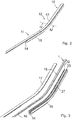
Figure 2 is a perspective view of the guide device according tofigure 1 ; -
Figure 3 is a dismantled perspective view of a guide device according to the invention and a rapier; -
Figure 4 is a section along line IV-IV infigure 2 on an enlarged scale; -
Figure 5 is a variant offigure 4 ; -
Figure 6 is another variant offigure 4 ; -
Figure 1 is a schematic view of a part of a gripper weaving machine with arapier 1 at which in use a gripper 2 is attached at thefront end 25 of therapier 1. The gripper 2 is either a so-called bringer gripper, or a so-called receiver gripper. Further adrive wheel 3 is illustrated for driving therapier 1 to and fro, that is driven by driving means (not illustrated). Therapier 1 is kept into contact with thedrive wheel 3 by means of guide blocks 4 and 5 assigned to thedrive wheel 3. Therapier 1 is flexible in order to allow therapier 1 to bend around thedrive wheel 3. Past theguide block 5 therapier 1 is guided in aguide device 6 according to the invention in order to guide therapier 1 to the lower side of the gripper weaving machine and/or below the shed 8 (indicated schematically). In this case theguide device 6 guides therear end 26 of arapier 1, this is the end of therapier 1 located opposite to thefront end 25 at which the gripper 2 is attached. Furthermore, another stationary guide 7 for therapier 1 is provided between thedrive wheel 3 and the shed 8 to guide therapier 1 from and to the shed 8. The stationary guide 7 and theguide device 6 are attached to a frame (not shown) of the weaving machine. Optionally also a horizontally arrangedguide 9 for therapier 1 is provided that is arranged such that theguide device 6 is arranged between thedrive wheel 3 and the horizontally arrangedguide 9. Theguide 9 is connected via a connectingelement 43 to theguide device 6. In this case theguide device 6 is arranged with respect to thedrive wheel 3 at the side of thedrive wheel 3 that is opposite to the side of thedrive wheel 3 at which the gripper 2 is arranged. Therapier 1 can also cooperate with aguide 29 arranged opposite to thedrive wheel 3. Therapier 1 can also cooperate with alubrication pin 30 and/or alubrication pin 31 in order to lubricate therapier 1. - The
guide device 6 in use is arranged at the side of thedrive wheel 3 opposite to the shed 8 in order to guide therapier 1 from thedrive wheel 3 to the lower side of the gripper weaving machine. Theguide device 6 in use is arranged tangentially with respect to thedrive wheel 3 in order to further guide therapier 1 from thedrive wheel 3. Theguide device 6 comprises a firststraight part 10 that in use is arranged adjacent to thedrive wheel 3. The firststraight part 10 of theguide device 6 is arranged tangentially with respect to thedrive wheel 3 in order to further guide therapier 1 from thedrive wheel 3. Theguide device 6 also comprises a secondstraight part 11 that in use is arranged farther away from thedrive wheel 3 and adjacent to the lower side of the gripper weaving machine. The firststraight part 10 and the secondstraight part 11 form an angle A with each other and are connected to each other via acurved transition section 12. Theguide device 6 according to the invention comprises at least onecooling device 13 intended to cool theguide device 6 at least in the area of thecurved transition section 12. The cooling near thecurved transition section 12 allows for cooling in an area where most heat is generated by friction between therapier 1 and theguide device 6, because at the height of thecurved transition section 12 therapier 1 pushes most on theguide device 6. Due to thecurved transition section 12 theguide device 6 is bent allowing to guide therapier 1 along theguide device 6 to the lower side of the gripper weaving machine. - As can be seen in
figures 1 ,2 ,3 and4 theguide device 6 comprises acooling device 13 which is formed by achannel 14 for a cooling fluid arranged in theguide device 6. Theguide device 6 comprises a first elongatedbended profile 15 in which thechannel 14 for the cooling fluid is provided. The first elongatedbended profile 15 cooperates with theouter surface 16 of therapier 1, this is the surface of thecurved rapier 1 located at the outer side of the shaped arch in therapier 1 and that can make contact with theprofile 15 of theguide device 6 as can be seen infigure 1 . Theguide device 6 comprises a second elongatedbended profile 17 attached to thefirst profile 15 and cooperating with theinner surface 18 of therapier 1, this is the surface of thecurved rapier 1 located at the inner side of the shaped arch of therapier 1 and that can make contact with theprofile 17 of theguide device 6 as can be seen infigures 1 and4 . As can best be seen infigure 4 thefirst profile 15 and thesecond profile 17 are connected relative to one another byconnections 19 and form together atubular guide device 6 in which therapier 1 can be guided with play. The shape of theprofile 15 and of the associatedprofile 17 is such that theprofiles straight part 10, the secondstraight part 11 and thecurved transition section 12. - The
cooling device 13 with thechannel 14 cooperates with thelubricating system 20 of the gripper weaving machine, so that for cooling theguide device 6 use is made of lubricating oil of the gripper weaving machine as the cooling fluid. Thelubricating system 20 is connected vialines channel 14. As indicated infigure 1 thechannel 14 for the cooling fluid extends over almost the full length of theguide device 6 in order to cool theguide device 6, more in particular extends between theconnector 41 for theline 21 and theconnector 42 for theline 22. By cooling theguide device 6 also therapier 1 is cooled. - As can be seen in
figure 4 theprofile 15 is provided with a guidingsurface 27 for theouter surface 16 of therapier 1 and theprofile 17 is provided with a guidingsurface 28 for theinner surface 18 of therapier 1. In this case theguide device 6 is provided with achannel 14 for the cooling fluid running near the guidingsurface 27. In this case theguide device 6 is formed by thefirst profile 15 and thesecond profile 17 which form together a tubular guide for therapier 1. The sides of therapier 1 are hereby guided by guidingelements profile 15 and for example are designed in the shape of a collar. - According to the invention the
guide device 6 with the firststraight part 10, the secondstraight part 11 and thecurved transition section 12, that connects the firststraight part 10 and the secondstraight part 11, is cooled by guiding a cooling fluid through thechannel 14 located near the guidingsurface 27 for therapier 1. Preferably, this cooling can take place over almost the full length of theguide device 6. As the heat is mainly generated in the area of thecurved transition section 12, it may be sufficient to cool theguide device 6 in the area of thecurved transition section 12. -
Figure 5 is a variant offigure 4 wherein thecooling device 13 comprises twochannels bended profile 15. Thecooling device 13 also comprises achannel 23 for the cooling fluid associated with the secondbended profile 17. In this case the sides of therapier 1 are guided by guidingelements second profile 17. -
Figure 6 is a variant offigure 4 wherein theguide device 6 is formed by a bendedtubular profile 36. Thecooling device 13 is formed by ahousing 37 cooperating with at least onecontact surface 38 of theguide device 6 formed by theprofile 36. As illustrated infigure 6 thehousing 37 is provided with two coolingchannels 39, that for example are provided with cooling fluid via the lubricating system 20 (illustrated infigure 1 ) of the gripper weaving machine. Thehousing 37 is arranged against the contact surfaces 38 of theprofile 36 of theguide device 6 in order to cool theguide device 6. - It is clear that in case the gripper weaving machine comprises a bringer gripper and a receiver gripper, at the height of each side of the gripper weaving machine a
drive wheel 3 for arapier 1 and associatedguide device 6 according to the invention can be arranged for therapier 1. - The guide device, the gripper weaving machine and the method according to the invention are not limited to the embodiments described by way of example and shown in the drawings. Variants and combinations of the described and shown embodiments that fall under the claims are also possible.
Claims (14)
- Guide device for guiding a rapier (1) in a gripper weaving machine, wherein in use the guide device (6) is arranged adjacent to a drive wheel (3) for driving the rapier (1) at a side opposite to the shed (8) in order to guide the rapier (1) between the drive wheel (3) and a lower side of the gripper weaving machine, wherein the guide device (6) comprises a first straight part (10) that in use is arranged adjacent to the drive wheel (3) and comprises a second straight part (11) that in use is arranged farther away from the drive wheel (3) at an angle (A) to the first straight part (10), and wherein the first straight part (10) and the second straight part (11) are connected to each other via a curved transition section (12), characterized in that the guide device (6) further comprises a cooling device (13) in order to cool the guide device (6) at least in the area of the curved transition section (12), wherein the guide device (6) is provided with at least one channel (14, 23, 24) for a cooling fluid running near a guiding surface (27, 28) for guiding the rapier (1).
- Guide device according to claim 1, characterized in that the guide device (6) comprises a first elongated profile (15) and a second elongated profile (17) that together form a tubular guide for the rapier (1).
- Guide device according to claim 1 or 2, characterized in that the guide device (6) comprises a first elongated profile (15) with a first guiding surface (27) for guiding an outer surface (16) of the rapier (1), which first elongated profile (15) is provided with at least one channel (14, 24) for the cooling fluid.
- Guide device according to claim 2 or 3, characterized in that the guide device (6) comprises a second elongated profile (17) with a second guiding surface (28) for guiding an inner surface (18) of the rapier (1) and that is attached to the first elongated profile (15).
- Guide device according to claim 4, characterized in that the second elongated profile (17) is provided with at least one channel (23) for the cooling fluid.
- Guide device according to any one of claims 1 to 5, characterized in that the at least one channel (14, 23, 24) for the cooling fluid extends over almost the full length of the guide device (6) in order to cool the guide device (6).
- Guide device according to any one of claims 1 to 6, characterized in that the cooling fluid is oil for the gripper weaving machine.
- Gripper weaving machine comprising a rapier (1), a drive wheel (3) for driving a rapier (1), wherein in use a gripper (2) is arranged at the front end (25) of the rapier (1), characterized in that the gripper weaving machine comprises a guide device (6) according to any one of claims 1 to 7 with a first straight part (10) and a second straight part (11) connected to each other via a curved transition section (12) in order to guide the rapier (1) between the drive wheel (3) and a lower side of the gripper weaving machine.
- Gripper weaving machine according to claim 8, characterized in that the rapier (1) is bent around the drive wheel (3) and in that the guide device (6) is arranged adjacent to the drive wheel (3) at a side opposite to the side of the drive wheel (3) at which the gripper (2) is arranged.
- Gripper weaving machine according to claim 8 or 9, characterized in that the guide device (6) comprises a first elongated profile (15) for guiding an outer surface (16) of the rapier (1), which first elongated profile (15) is provided with at least one channel (14, 24) for the cooling fluid.
- Gripper weaving machine according to any one of claims 8 to 10, characterized in that the first straight part (10) of the guide device (6) is arranged tangentially with respect to the drive wheel (3) in order to guide the rapier (1) from and to the drive wheel (3).
- Gripper weaving machine according to any one of claims 8 to 11, characterized in that the guide device (6) is arranged between the drive wheel (3) and a horizontally arranged guide (9) for the rapier (1).
- Method for cooling a guide device (6) according to any one of claims 1 to 7 with a first straight part (10) and a second straight part (11) connected to each other via a curved transition section (12) in order to guide the rapier (1) between the drive wheel (3) and a lower side of the gripper weaving machine, characterized in that the method comprises cooling the guide device (6), wherein the cooling comprises the guiding of a cooling fluid at least in the area of the curved transition section (12) of the guide device (6).
- Method according to claim 13, characterized in that the cooling fluid is an oil of the gripper weaving machine.
Applications Claiming Priority (2)
| Application Number | Priority Date | Filing Date | Title |
|---|---|---|---|
| BE2015/0078A BE1022754B1 (en) | 2015-02-26 | 2015-02-26 | GUIDANCE DEVICE FOR A LANS FOR A GRIPPER WEAVING MACHINE |
| PCT/EP2016/052858 WO2016134973A1 (en) | 2015-02-26 | 2016-02-10 | Guide device for a rapier in a gripper weaving machine |
Publications (2)
| Publication Number | Publication Date |
|---|---|
| EP3262222A1 EP3262222A1 (en) | 2018-01-03 |
| EP3262222B1 true EP3262222B1 (en) | 2019-12-18 |
Family
ID=53189529
Family Applications (1)
| Application Number | Title | Priority Date | Filing Date |
|---|---|---|---|
| EP16703803.3A Active EP3262222B1 (en) | 2015-02-26 | 2016-02-10 | Guide device for a rapier in a gripper weaving machine |
Country Status (4)
| Country | Link |
|---|---|
| EP (1) | EP3262222B1 (en) |
| CN (1) | CN107250451B (en) |
| BE (1) | BE1022754B1 (en) |
| WO (1) | WO2016134973A1 (en) |
Cited By (2)
| Publication number | Priority date | Publication date | Assignee | Title |
|---|---|---|---|---|
| EP4112792A1 (en) | 2021-06-29 | 2023-01-04 | Picanol | Rapier wheel |
| EP3821064B1 (en) * | 2019-06-18 | 2023-11-29 | ITEMA S.p.A. | Control method of a weft insertion system of a gripper loom |
Families Citing this family (3)
| Publication number | Priority date | Publication date | Assignee | Title |
|---|---|---|---|---|
| CN107700039A (en) * | 2017-10-19 | 2018-02-16 | 广东康特斯织造装备有限公司 | Using the stop mechanism for towel machine of narrow sword belt wefting insertion |
| BE1027262B1 (en) * | 2019-05-07 | 2020-12-08 | Vandewiele Nv | GUIDING DEVICE FOR A GRABBLE ROD AND JACKET WEAVING MACHINE CONTAINING SUCH GUIDING DEVICE |
| CN115029843A (en) * | 2022-01-30 | 2022-09-09 | 绍兴丰煊纺织品有限公司 | Rapier tape heat dissipation device of rapier machine |
Family Cites Families (14)
| Publication number | Priority date | Publication date | Assignee | Title |
|---|---|---|---|---|
| CH531594A (en) * | 1971-10-29 | 1972-12-15 | Fischer Ag Brugg Georg | Lubricator - for gripper belt and guide of a shuttless loom |
| GB1396492A (en) * | 1973-01-31 | 1975-06-04 | Providence Pile Fabric Corp | Rapier loom |
| CH577577A5 (en) * | 1974-12-24 | 1976-07-15 | Rueti Ag Maschf | |
| DE2743303C3 (en) * | 1977-09-27 | 1980-06-12 | Lindauer Dornier Gesellschaft Mbh, 8990 Lindau | Weaving machine with weft insertion through insertion elements that can be pushed forward and back into the shed alternately |
| DE2902729C2 (en) * | 1979-01-25 | 1982-04-01 | Lindauer Dornier Gmbh, 8990 Lindau | Weft insertion element for shuttleless looms |
| DE3800281A1 (en) * | 1987-03-05 | 1988-09-15 | Sulzer Ag | WEAVING MACHINE WITH PROJECTILE FAN BRAKE |
| DE3709889A1 (en) * | 1987-03-26 | 1988-10-13 | Dornier Gmbh Lindauer | Drive device for the gripper bars of shuttleless weaving machines |
| WO1988007600A1 (en) * | 1987-04-03 | 1988-10-06 | Textilma Ag | Gripper weaving machine |
| BE1000506A4 (en) * | 1987-04-28 | 1989-01-03 | Picanol Nv | Loom-grip drive cooling system - force-cools belt guides whenever machine stops |
| IT1230810B (en) * | 1989-08-09 | 1991-10-29 | Vamatex Spa | VARIABLE THICKNESS PLIER BELT FOR CLAMPS WEAVING FRAMES. |
| CN2161626Y (en) * | 1993-01-05 | 1994-04-13 | 陈金朝 | Textile machine sword belt cooling device |
| DE19538287C1 (en) * | 1995-10-14 | 1997-06-19 | Dornier Gmbh Lindauer | Loom with coolable rapier drive |
| CN201058907Y (en) * | 2007-06-29 | 2008-05-14 | 太平洋机电(集团)有限公司 | Gripper band guide-rail device having cleaning and radiating mechanism |
| CN203159826U (en) * | 2013-02-28 | 2013-08-28 | 常州市武进恒通金属钢丝有限公司 | Weft insertion mechanism of braiding net machine |
-
2015
- 2015-02-26 BE BE2015/0078A patent/BE1022754B1/en not_active IP Right Cessation
-
2016
- 2016-02-10 CN CN201680012250.4A patent/CN107250451B/en active Active
- 2016-02-10 EP EP16703803.3A patent/EP3262222B1/en active Active
- 2016-02-10 WO PCT/EP2016/052858 patent/WO2016134973A1/en not_active Ceased
Non-Patent Citations (1)
| Title |
|---|
| None * |
Cited By (5)
| Publication number | Priority date | Publication date | Assignee | Title |
|---|---|---|---|---|
| EP3821064B1 (en) * | 2019-06-18 | 2023-11-29 | ITEMA S.p.A. | Control method of a weft insertion system of a gripper loom |
| EP4112792A1 (en) | 2021-06-29 | 2023-01-04 | Picanol | Rapier wheel |
| WO2023274701A1 (en) | 2021-06-29 | 2023-01-05 | Picanol | Rapier wheel |
| BE1029465A1 (en) | 2021-06-29 | 2023-01-06 | Picanol Nv | Lance wheel for a lance weaving machine |
| BE1029465B1 (en) * | 2021-06-29 | 2023-03-22 | Picanol Nv | Lance wheel for a lance weaving machine |
Also Published As
| Publication number | Publication date |
|---|---|
| BE1022754A1 (en) | 2016-08-30 |
| CN107250451B (en) | 2019-08-27 |
| WO2016134973A1 (en) | 2016-09-01 |
| EP3262222A1 (en) | 2018-01-03 |
| BE1022754B1 (en) | 2016-08-30 |
| CN107250451A (en) | 2017-10-13 |
Similar Documents
| Publication | Publication Date | Title |
|---|---|---|
| WO2016134973A1 (en) | Guide device for a rapier in a gripper weaving machine | |
| KR101030704B1 (en) | Skating trolley for cable protection guide device | |
| CN105089709B (en) | Airfoil with improved cooling | |
| JP2008544185A (en) | Linear guide rail for linear guide system with coolant slot | |
| US7755226B2 (en) | Stand for a linear electric motor comprising thermal compensation and cooling means | |
| WO2014094082A1 (en) | Heat exchange system for casings of rotary electric machines | |
| EP3966375B1 (en) | Guide device for a rapier bar and rapier weaving machine comprising such a guide device | |
| CN107964713B (en) | Cooling device for synthetic threads | |
| US11199222B2 (en) | Motion guide device | |
| CN105228423A (en) | A kind of Weaving type radiator being applied to electronic devices and components | |
| JP5396973B2 (en) | Cooling mechanism of machine base sliding part in mold clamping device | |
| CN214919588U (en) | Double-point beating device for air conditioner copper pipe | |
| KR101698475B1 (en) | Cleaning Tip and Lip cleaner having the same | |
| US20110120792A1 (en) | Air guide device for front face structure of vehicle | |
| CN1774530B (en) | Drive unit for a loom heald frame | |
| CN104440976B (en) | A kind of guillotine with heater | |
| CN103192228B (en) | Steel belt knurl device | |
| BE1024400A1 (en) | Device for cutting pile threads on a weaving machine | |
| CN215092437U (en) | Flexible servo machine tool feeding and discharging gripping apparatus | |
| CN211601636U (en) | heat dissipation structure | |
| CN109338570A (en) | Circular weaving machine big cam and heald bar rise and fall the transmission mechanism of component | |
| CN117026464A (en) | A polypropylene monofilament fabric and its production process | |
| CN213497055U (en) | Hydraulic power system of full-automatic woodworking hot press | |
| US2452690A (en) | Check strap | |
| CN200985409Y (en) | Xiphoid belt guiding mechanism for xiphoid belt loom |
Legal Events
| Date | Code | Title | Description |
|---|---|---|---|
| STAA | Information on the status of an ep patent application or granted ep patent |
Free format text: STATUS: THE INTERNATIONAL PUBLICATION HAS BEEN MADE |
|
| PUAI | Public reference made under article 153(3) epc to a published international application that has entered the european phase |
Free format text: ORIGINAL CODE: 0009012 |
|
| STAA | Information on the status of an ep patent application or granted ep patent |
Free format text: STATUS: REQUEST FOR EXAMINATION WAS MADE |
|
| 17P | Request for examination filed |
Effective date: 20170825 |
|
| AK | Designated contracting states |
Kind code of ref document: A1 Designated state(s): AL AT BE BG CH CY CZ DE DK EE ES FI FR GB GR HR HU IE IS IT LI LT LU LV MC MK MT NL NO PL PT RO RS SE SI SK SM TR |
|
| AX | Request for extension of the european patent |
Extension state: BA ME |
|
| DAV | Request for validation of the european patent (deleted) | ||
| DAX | Request for extension of the european patent (deleted) | ||
| GRAP | Despatch of communication of intention to grant a patent |
Free format text: ORIGINAL CODE: EPIDOSNIGR1 |
|
| STAA | Information on the status of an ep patent application or granted ep patent |
Free format text: STATUS: GRANT OF PATENT IS INTENDED |
|
| INTG | Intention to grant announced |
Effective date: 20190809 |
|
| GRAS | Grant fee paid |
Free format text: ORIGINAL CODE: EPIDOSNIGR3 |
|
| GRAA | (expected) grant |
Free format text: ORIGINAL CODE: 0009210 |
|
| STAA | Information on the status of an ep patent application or granted ep patent |
Free format text: STATUS: THE PATENT HAS BEEN GRANTED |
|
| AK | Designated contracting states |
Kind code of ref document: B1 Designated state(s): AL AT BE BG CH CY CZ DE DK EE ES FI FR GB GR HR HU IE IS IT LI LT LU LV MC MK MT NL NO PL PT RO RS SE SI SK SM TR |
|
| REG | Reference to a national code |
Ref country code: CH Ref legal event code: EP |
|
| REG | Reference to a national code |
Ref country code: DE Ref legal event code: R096 Ref document number: 602016026323 Country of ref document: DE |
|
| REG | Reference to a national code |
Ref country code: IE Ref legal event code: FG4D |
|
| REG | Reference to a national code |
Ref country code: AT Ref legal event code: REF Ref document number: 1214701 Country of ref document: AT Kind code of ref document: T Effective date: 20200115 |
|
| REG | Reference to a national code |
Ref country code: NL Ref legal event code: MP Effective date: 20191218 |
|
| PG25 | Lapsed in a contracting state [announced via postgrant information from national office to epo] |
Ref country code: FI Free format text: LAPSE BECAUSE OF FAILURE TO SUBMIT A TRANSLATION OF THE DESCRIPTION OR TO PAY THE FEE WITHIN THE PRESCRIBED TIME-LIMIT Effective date: 20191218 Ref country code: BG Free format text: LAPSE BECAUSE OF FAILURE TO SUBMIT A TRANSLATION OF THE DESCRIPTION OR TO PAY THE FEE WITHIN THE PRESCRIBED TIME-LIMIT Effective date: 20200318 Ref country code: SE Free format text: LAPSE BECAUSE OF FAILURE TO SUBMIT A TRANSLATION OF THE DESCRIPTION OR TO PAY THE FEE WITHIN THE PRESCRIBED TIME-LIMIT Effective date: 20191218 Ref country code: LV Free format text: LAPSE BECAUSE OF FAILURE TO SUBMIT A TRANSLATION OF THE DESCRIPTION OR TO PAY THE FEE WITHIN THE PRESCRIBED TIME-LIMIT Effective date: 20191218 Ref country code: LT Free format text: LAPSE BECAUSE OF FAILURE TO SUBMIT A TRANSLATION OF THE DESCRIPTION OR TO PAY THE FEE WITHIN THE PRESCRIBED TIME-LIMIT Effective date: 20191218 Ref country code: NO Free format text: LAPSE BECAUSE OF FAILURE TO SUBMIT A TRANSLATION OF THE DESCRIPTION OR TO PAY THE FEE WITHIN THE PRESCRIBED TIME-LIMIT Effective date: 20200318 Ref country code: GR Free format text: LAPSE BECAUSE OF FAILURE TO SUBMIT A TRANSLATION OF THE DESCRIPTION OR TO PAY THE FEE WITHIN THE PRESCRIBED TIME-LIMIT Effective date: 20200319 |
|
| REG | Reference to a national code |
Ref country code: LT Ref legal event code: MG4D |
|
| PG25 | Lapsed in a contracting state [announced via postgrant information from national office to epo] |
Ref country code: HR Free format text: LAPSE BECAUSE OF FAILURE TO SUBMIT A TRANSLATION OF THE DESCRIPTION OR TO PAY THE FEE WITHIN THE PRESCRIBED TIME-LIMIT Effective date: 20191218 Ref country code: RS Free format text: LAPSE BECAUSE OF FAILURE TO SUBMIT A TRANSLATION OF THE DESCRIPTION OR TO PAY THE FEE WITHIN THE PRESCRIBED TIME-LIMIT Effective date: 20191218 |
|
| PG25 | Lapsed in a contracting state [announced via postgrant information from national office to epo] |
Ref country code: AL Free format text: LAPSE BECAUSE OF FAILURE TO SUBMIT A TRANSLATION OF THE DESCRIPTION OR TO PAY THE FEE WITHIN THE PRESCRIBED TIME-LIMIT Effective date: 20191218 |
|
| PG25 | Lapsed in a contracting state [announced via postgrant information from national office to epo] |
Ref country code: NL Free format text: LAPSE BECAUSE OF FAILURE TO SUBMIT A TRANSLATION OF THE DESCRIPTION OR TO PAY THE FEE WITHIN THE PRESCRIBED TIME-LIMIT Effective date: 20191218 Ref country code: PT Free format text: LAPSE BECAUSE OF FAILURE TO SUBMIT A TRANSLATION OF THE DESCRIPTION OR TO PAY THE FEE WITHIN THE PRESCRIBED TIME-LIMIT Effective date: 20200513 Ref country code: CZ Free format text: LAPSE BECAUSE OF FAILURE TO SUBMIT A TRANSLATION OF THE DESCRIPTION OR TO PAY THE FEE WITHIN THE PRESCRIBED TIME-LIMIT Effective date: 20191218 Ref country code: RO Free format text: LAPSE BECAUSE OF FAILURE TO SUBMIT A TRANSLATION OF THE DESCRIPTION OR TO PAY THE FEE WITHIN THE PRESCRIBED TIME-LIMIT Effective date: 20191218 Ref country code: EE Free format text: LAPSE BECAUSE OF FAILURE TO SUBMIT A TRANSLATION OF THE DESCRIPTION OR TO PAY THE FEE WITHIN THE PRESCRIBED TIME-LIMIT Effective date: 20191218 |
|
| PG25 | Lapsed in a contracting state [announced via postgrant information from national office to epo] |
Ref country code: SM Free format text: LAPSE BECAUSE OF FAILURE TO SUBMIT A TRANSLATION OF THE DESCRIPTION OR TO PAY THE FEE WITHIN THE PRESCRIBED TIME-LIMIT Effective date: 20191218 Ref country code: SK Free format text: LAPSE BECAUSE OF FAILURE TO SUBMIT A TRANSLATION OF THE DESCRIPTION OR TO PAY THE FEE WITHIN THE PRESCRIBED TIME-LIMIT Effective date: 20191218 Ref country code: IS Free format text: LAPSE BECAUSE OF FAILURE TO SUBMIT A TRANSLATION OF THE DESCRIPTION OR TO PAY THE FEE WITHIN THE PRESCRIBED TIME-LIMIT Effective date: 20200418 |
|
| REG | Reference to a national code |
Ref country code: DE Ref legal event code: R097 Ref document number: 602016026323 Country of ref document: DE |
|
| REG | Reference to a national code |
Ref country code: CH Ref legal event code: PL |
|
| REG | Reference to a national code |
Ref country code: AT Ref legal event code: MK05 Ref document number: 1214701 Country of ref document: AT Kind code of ref document: T Effective date: 20191218 |
|
| PLBE | No opposition filed within time limit |
Free format text: ORIGINAL CODE: 0009261 |
|
| STAA | Information on the status of an ep patent application or granted ep patent |
Free format text: STATUS: NO OPPOSITION FILED WITHIN TIME LIMIT |
|
| PG25 | Lapsed in a contracting state [announced via postgrant information from national office to epo] |
Ref country code: DK Free format text: LAPSE BECAUSE OF FAILURE TO SUBMIT A TRANSLATION OF THE DESCRIPTION OR TO PAY THE FEE WITHIN THE PRESCRIBED TIME-LIMIT Effective date: 20191218 Ref country code: LU Free format text: LAPSE BECAUSE OF NON-PAYMENT OF DUE FEES Effective date: 20200210 Ref country code: ES Free format text: LAPSE BECAUSE OF FAILURE TO SUBMIT A TRANSLATION OF THE DESCRIPTION OR TO PAY THE FEE WITHIN THE PRESCRIBED TIME-LIMIT Effective date: 20191218 Ref country code: MC Free format text: LAPSE BECAUSE OF FAILURE TO SUBMIT A TRANSLATION OF THE DESCRIPTION OR TO PAY THE FEE WITHIN THE PRESCRIBED TIME-LIMIT Effective date: 20191218 |
|
| 26N | No opposition filed |
Effective date: 20200921 |
|
| PG25 | Lapsed in a contracting state [announced via postgrant information from national office to epo] |
Ref country code: AT Free format text: LAPSE BECAUSE OF FAILURE TO SUBMIT A TRANSLATION OF THE DESCRIPTION OR TO PAY THE FEE WITHIN THE PRESCRIBED TIME-LIMIT Effective date: 20191218 Ref country code: SI Free format text: LAPSE BECAUSE OF FAILURE TO SUBMIT A TRANSLATION OF THE DESCRIPTION OR TO PAY THE FEE WITHIN THE PRESCRIBED TIME-LIMIT Effective date: 20191218 Ref country code: CH Free format text: LAPSE BECAUSE OF NON-PAYMENT OF DUE FEES Effective date: 20200229 Ref country code: LI Free format text: LAPSE BECAUSE OF NON-PAYMENT OF DUE FEES Effective date: 20200229 |
|
| PG25 | Lapsed in a contracting state [announced via postgrant information from national office to epo] |
Ref country code: FR Free format text: LAPSE BECAUSE OF NON-PAYMENT OF DUE FEES Effective date: 20200218 Ref country code: IE Free format text: LAPSE BECAUSE OF NON-PAYMENT OF DUE FEES Effective date: 20200210 |
|
| PG25 | Lapsed in a contracting state [announced via postgrant information from national office to epo] |
Ref country code: PL Free format text: LAPSE BECAUSE OF FAILURE TO SUBMIT A TRANSLATION OF THE DESCRIPTION OR TO PAY THE FEE WITHIN THE PRESCRIBED TIME-LIMIT Effective date: 20191218 |
|
| GBPC | Gb: european patent ceased through non-payment of renewal fee |
Effective date: 20200318 |
|
| PG25 | Lapsed in a contracting state [announced via postgrant information from national office to epo] |
Ref country code: GB Free format text: LAPSE BECAUSE OF NON-PAYMENT OF DUE FEES Effective date: 20200318 |
|
| PG25 | Lapsed in a contracting state [announced via postgrant information from national office to epo] |
Ref country code: MT Free format text: LAPSE BECAUSE OF FAILURE TO SUBMIT A TRANSLATION OF THE DESCRIPTION OR TO PAY THE FEE WITHIN THE PRESCRIBED TIME-LIMIT Effective date: 20191218 Ref country code: CY Free format text: LAPSE BECAUSE OF FAILURE TO SUBMIT A TRANSLATION OF THE DESCRIPTION OR TO PAY THE FEE WITHIN THE PRESCRIBED TIME-LIMIT Effective date: 20191218 |
|
| PG25 | Lapsed in a contracting state [announced via postgrant information from national office to epo] |
Ref country code: MK Free format text: LAPSE BECAUSE OF FAILURE TO SUBMIT A TRANSLATION OF THE DESCRIPTION OR TO PAY THE FEE WITHIN THE PRESCRIBED TIME-LIMIT Effective date: 20191218 |
|
| PGFP | Annual fee paid to national office [announced via postgrant information from national office to epo] |
Ref country code: TR Payment date: 20230209 Year of fee payment: 8 Ref country code: IT Payment date: 20230228 Year of fee payment: 8 Ref country code: DE Payment date: 20230223 Year of fee payment: 8 Ref country code: BE Payment date: 20230110 Year of fee payment: 8 |
|
| P01 | Opt-out of the competence of the unified patent court (upc) registered |
Effective date: 20230519 |
|
| REG | Reference to a national code |
Ref country code: DE Ref legal event code: R119 Ref document number: 602016026323 Country of ref document: DE |
|
| REG | Reference to a national code |
Ref country code: BE Ref legal event code: MM Effective date: 20240229 |
|
| PG25 | Lapsed in a contracting state [announced via postgrant information from national office to epo] |
Ref country code: DE Free format text: LAPSE BECAUSE OF NON-PAYMENT OF DUE FEES Effective date: 20240903 |
|
| PG25 | Lapsed in a contracting state [announced via postgrant information from national office to epo] |
Ref country code: BE Free format text: LAPSE BECAUSE OF NON-PAYMENT OF DUE FEES Effective date: 20240229 |
|
| PG25 | Lapsed in a contracting state [announced via postgrant information from national office to epo] |
Ref country code: DE Free format text: LAPSE BECAUSE OF NON-PAYMENT OF DUE FEES Effective date: 20240903 Ref country code: BE Free format text: LAPSE BECAUSE OF NON-PAYMENT OF DUE FEES Effective date: 20240229 |
|
| PG25 | Lapsed in a contracting state [announced via postgrant information from national office to epo] |
Ref country code: IT Free format text: LAPSE BECAUSE OF NON-PAYMENT OF DUE FEES Effective date: 20240210 |