EP3261915B1 - Adjustable buoyancy clamp for hose - Google Patents
Adjustable buoyancy clamp for hose Download PDFInfo
- Publication number
- EP3261915B1 EP3261915B1 EP16707060.6A EP16707060A EP3261915B1 EP 3261915 B1 EP3261915 B1 EP 3261915B1 EP 16707060 A EP16707060 A EP 16707060A EP 3261915 B1 EP3261915 B1 EP 3261915B1
- Authority
- EP
- European Patent Office
- Prior art keywords
- buoy
- buoy device
- bladder
- unit
- shell
- Prior art date
- Legal status (The legal status is an assumption and is not a legal conclusion. Google has not performed a legal analysis and makes no representation as to the accuracy of the status listed.)
- Active
Links
- 239000012530 fluid Substances 0.000 claims description 16
- XLYOFNOQVPJJNP-UHFFFAOYSA-N water Substances O XLYOFNOQVPJJNP-UHFFFAOYSA-N 0.000 claims description 15
- 238000000034 method Methods 0.000 claims description 9
- 239000000463 material Substances 0.000 claims description 4
- 229920001971 elastomer Polymers 0.000 claims description 3
- 208000034699 Vitreous floaters Diseases 0.000 description 3
- 230000015572 biosynthetic process Effects 0.000 description 2
- 239000004033 plastic Substances 0.000 description 2
- 229920003023 plastic Polymers 0.000 description 2
- 239000013535 sea water Substances 0.000 description 2
- 239000004215 Carbon black (E152) Substances 0.000 description 1
- 230000009172 bursting Effects 0.000 description 1
- 230000001276 controlling effect Effects 0.000 description 1
- 230000001419 dependent effect Effects 0.000 description 1
- 229920001903 high density polyethylene Polymers 0.000 description 1
- 239000004700 high-density polyethylene Substances 0.000 description 1
- 229930195733 hydrocarbon Natural products 0.000 description 1
- 150000002430 hydrocarbons Chemical class 0.000 description 1
- 229920002681 hypalon Polymers 0.000 description 1
- 230000003116 impacting effect Effects 0.000 description 1
- 239000007788 liquid Substances 0.000 description 1
- 230000002028 premature Effects 0.000 description 1
- 230000001105 regulatory effect Effects 0.000 description 1
- 230000000284 resting effect Effects 0.000 description 1
- 239000004753 textile Substances 0.000 description 1
Images


Classifications
-
- F—MECHANICAL ENGINEERING; LIGHTING; HEATING; WEAPONS; BLASTING
- F16—ENGINEERING ELEMENTS AND UNITS; GENERAL MEASURES FOR PRODUCING AND MAINTAINING EFFECTIVE FUNCTIONING OF MACHINES OR INSTALLATIONS; THERMAL INSULATION IN GENERAL
- F16L—PIPES; JOINTS OR FITTINGS FOR PIPES; SUPPORTS FOR PIPES, CABLES OR PROTECTIVE TUBING; MEANS FOR THERMAL INSULATION IN GENERAL
- F16L1/00—Laying or reclaiming pipes; Repairing or joining pipes on or under water
- F16L1/12—Laying or reclaiming pipes on or under water
- F16L1/20—Accessories therefor, e.g. floats or weights
- F16L1/24—Floats; Weights
Definitions
- the present invention relates to buoy systems for marine hoses, and more specifically to an inflatable buoy device, also called a floater of adjustable buoyancy, for such a hose.
- hoses are commonly used to transfer e.g. hydrocarbon liquids in marine environment.
- many different kinds of configurations exist depending on the equipment, the water depth, the fluid density which is to be conveyed, the site conditions, etc.
- One method is to provide different types of buoy systems in order to control the buoyancy of the hose, where buoys are clamped at predetermined locations along the hose.
- the hose may be used on the surface of the water, on the bottom of the sea, or vertically down from a ship or a calm buoy to e.g. a PLEM (Pipeline End Manifold) located on the seabed.
- PLEM Peline End Manifold
- buoy systems are not easily adjustable to receive different products of different density that are conveyed in the hose.
- density of one conveyed product may differ from another conveyed product which means that the load on the hose may vary impacting the configuration, thus the hose loading may lead to premature failure.
- the load varies on the hose, the load also varies on the buoy system.
- These buoy systems are often permanent and it would require divers to be able to add or remove buoy modules, or collar floaters, from the buoy system on the submarine line in order to adjust the configuration to the new load. Examples of such systems are disclosed in WO2014149267A1 , US7179144B2 and US4159189A . Further background art is known from GB965270A , CN201651546U and EP1980778A2 .
- Another problem with existing buoy systems is when a system and a marine hose is located on the sea surface, e.g. near shores, and ships need to pass through the area.
- An object of the present invention is to provide improvements over prior art. This object is achieved by the concept defined in the appended independent claims; certain embodiments being set forth in the related dependent claims.
- a buoy device for a marine hose or the like, wherein the buoy device is configured to at least partly enclose the hose.
- the buoy device comprises a shell unit and a bladder unit which is arranged within the shell unit and which is inflatable and/or deflatable by means of a fluid in order to adjust the buoyancy of the buoy device during use.
- One of the advantages with this buoy device is that it is not a permanent device, it may instead be inflated or deflated depending on the situation and the purpose of the marine hose. Thus, it is in no need for external help, such as divers when adjusting the position of the hose.
- a further advantage is that the buoy device can be mounted on existing hoses. There is thus no need for an expensive special hose.
- the bladder unit is protected by the shell unit such that the risk of damaging the bladder unit due to wear on the seabed is reduced.
- the bladder unit of the buoy device of the first aspect comprises a first bladder element and a second bladder element, wherein the first bladder element is arranged within the first shell element and the second bladder element is arranged within the second shell element.
- This facilitates the assembly of the bladder unit within the shell unit, and during assembly of the buoy device to the hose the bladder unit does not have to be taken into consideration.
- Another advantage of having two separate bladder elements each located in a shell element is that the buoy device may be clamped onto the marine hose at any location without dismantling the hose structure.
- Yet another advantage with a two-parted bladder unit is that, in the unlikely event that one of the bladder elements is punctuated, there is another bladder element, still being inflated, and providing buoyancy to the buoy device.
- the shell unit comprises a number of openings through which water may flow during the inflation and deflation of the bladder unit.
- the openings make it even easier to inflate and deflate the bladder unit, as the water easily can flow into the device from the outside and vice versa.
- the shell unit comprises a first shell element and a second shell element, which in an assembled state are connected to each other.
- the first and second shell element simplify the assembly of the buoy device to or around the marine hose.
- the first and second shell elements have a substantially semi-circular shape. This is an advantage, especially during assembly, to have a shape that corresponds to the marine hose.
- a first end portion of the first shell element is hinged to a first end portion of the second shell element, and a second end portion of the first shell element is connected by connection means to a second end portion of the second shell element in an assembled state. This even more simplifies the assembly of the buoy device around the marine hose.
- the buoy device further comprises at least one pressure relief valve which is connected to the bladder unit and which is configured to prevent an over pressure in the bladder unit, which could lead to the bladder element bursting.
- the buoy device further comprises at least one inflation socket which is connected to the bladder unit and which is configured to be connected to an air supply source, wherein the inflation socket is configured to inflate and/or deflate the bladder unit.
- the inflation socket is connected to a control unit which is configured to control the amount of fluid inflated into the bladder unit, in order to adjust the buoyancy of the buoy device during use.
- a system of buoy devices according to the first aspect where the buoy devices are configured to be arranged spaced apart from each other when attached to a marine hose.
- the different buoy devices may be equally or differently inflated, in order to adjust and enhance the buoyancy of the marine hose.
- a system of buoy devices according to the first aspect where one buoy device is configured to be arranged adjacent at least one other buoy device when attached to a marine hose. In that way, extra buoyancy is provided in certain locations, which may be extra exposed.
- a marine hose comprising a number of buoy devices.
- a fifth aspect of the invention there is provided a method of adjusting the buoyancy of a buoy device according to the first aspect, comprising the steps of:
- a method for controlling the buoyancy of a marine hose at least partly enclosed by at least one buoyancy device comprises the step of inflating or deflating one or more of the at least one buoyancy device according to the first aspect. This is advantageous when different buoyancies are desired at different locations along the marine hose.
- buoy device 1 which from now on is also called a buoy clamp and which may also be seen as a floater of adjustable buoyancy.
- the buoy clamp 1 is configured to, at least partly or, as in this case totally, enclose a marine hose H during use in order to adjust the buoyancy of it (see Figs 9-10 ).
- the hose H is e.g. a marine hose which is used in sea water for transporting various fluids.
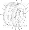
- the buoy device 1 comprises a shell unit 2 and a bladder unit 3 arranged within the shell unit 2.
- the whole bladder unit 3 fits within the shell unit 2, such that the shell unit 2 covers the major part of the periphery of the bladder unit 3.
- the shell unit 2 is annularly formed such that it can be placed around the periphery of the marine hose H, which extends through the central opening of the shell unit 2. This is shown e.g. in Figs 9-10 .
- the bladder unit 3 is inflatable and/or deflatable by means of a fluid, e.g. a gas like air, in order to adjust the buoyancy of the buoy device 1 during use.
- the shell unit 2 comprises a number of openings 4a-4c (shown e.g. in Fig. 2 ) through which e.g. sea water may flow during the inflation and deflation of the bladder unit 3.
- Fig. 2 shows an example of three openings 4a-4c located on the inner surface of the shell unit 2.
- the number of openings 4 and their locations in the shell unit 2 are such that the buoy clamp 1 is always allowed to take in water no matter its location or orientation in water.
- the openings 4 preferably are not only located in one area of the shell unit 2 since the buoy clamp 1 is then not able to take in water if this area is located only surrounded by air.
- the openings 4 may not only be located on the inner surface of the shell unit 2 but also on its sides or outer surface.
- the shell unit 2 comprises a first shell element 5 and a second shell element 6 which in an assembled state are connected to each other, see e.g. Figs 1 and 2 .
- Each first and second shell element 5, 6 has a substantially semi-circular shape for enclosing a hose H.
- the size of the two shell elements 5, 6 depends on the size of the hose H and may therefor be made with different inner diameter in order to fit different sizes of hoses.
- the shell unit 2 is preferably made of a plastic material, e.g. HDPE; most preferred it is made of a rigid or semi-rigid plastics material.
- a first end portion 8a of the first shell element 5 is hinged to a first end portion 9a of the second shell element 6, and a second end portion 8b of the first shell element 5 is connected by connection means 10 to a second end portion 9b of the second shell element 6 in an assembled state.
- the connection means are preferably screws 10a, 10b.
- the bladder unit 3 comprises a first bladder element 12 and a second bladder element 13.
- the first bladder element 12 is arranged within the first shell element 5 and the second bladder element 13 is arranged within the second shell element 6, see Fig. 1 .
- Each bladder element 12, 13 may be in a deflated state or an inflated state, see examples in Figs 7 and 8 .
- the bladder element 13 is deflated and it is curled up along the periphery of the shell element 6.
- the bladder element 13 is inflated and almost fills the inner space of the shell element 6.
- the bladder elements 12, 13 are inflated by air or any other gas, but they can in other embodiments be inflated by any type of fluid.
- the buoyancy of the buoy clamp 1 is determined on the inflation of the bladder unit 3, i.e. of the bladder elements 12, 13.
- One part of the buoy clamp 1, where the first shell element 5 and the first bladder element 12 constitute this one part, is preferably identical to the other part of the buoy clamp 1, where the second shell element 5 and the second bladder element 13 constitute the other part.
- the buoy clamp 1 When assembling the buoy clamp 1 one of the parts is rotated 180°. The buoy clamp 1 is thus mirror symmetrical.
- Each bladder element 12, 13 is fastened to respective shell element 5, 6 by fastening means 15a-f, 16a-f, preferably bolts, which extend though the outer surface of each shell element 5, 6.
- the bladder unit 3, i.e. the two bladder elements 12, 13 is made of a textile which is coated with a flexible rubber material, e.g. Hypalon® rubber.
- the buoy clamp 1 includes two pressure relief valves 18, 19, where one is arranged on each shell element 5, 6.
- the relief valves 18, 19 are connected to the bladder unit 3 and are configured to prevent an over pressure in the same.
- the buoy clamp 1 also includes four inflation sockets 20a, 20b, 21a, 21b, where two are arranged on each shell element 5, 6.
- the inflation sockets 20a, 20b, 21a, 21b are connected to the bladder unit 3, and to an air supply source A, e.g. an air supply pipe, see Figs 9 and 10 . They are configured to inflate and partly deflate each bladder element 12, 13 preferably by means of air from the air supply source A.
- the air supply source A is a main air conduit which runs in parallel to the hose H and feeds each module 1 in parallel.
- the inflation sockets 20a, 20b, 21a, 21b are also connected to a control unit 22, seen in Fig. 3 , by which an operator can control and activate/deactivate inflation or deflation.
- the control unit 22 is preferably arranged on a ship or on land so that the operator remotely can control the operation.
- the control unit 22 is able to control the flow rate inflated into the bladder unit 3 in order to adjust the buoyancy of the buoy device 1 during use in e.g. water.
- the inflation sockets 20a, 20b, 21a, 21b is connected to the control unit 22 in order to, together with the pressure relief valve 18, 19, control the simultaneous inflation of several bladder units 3 located at different water depths.
- the control unit 22 includes two flow control modules 23, 24 which are connected to two of the inflation sockets 20a, 21a.
- the flow control modules 23, 24 are able to limit the air flow rate and thus limit the inflation speed and the exhausted water flow rate. Furthermore, the flow control modules 23, 24 allow for a pressure drop during the inflation phase. Deeper positioned modules 1 are permitted to inflate whereas modules 1 positioned closer to the surface are already exhausting air by their relief valves 18, 19.
- the air inflating the buoy device 1 is injected from the surface and exhausted at the surface by the same hose or pipe.
- the air runs mainly through a non return valve (not shown) of the flow control modules 23, 24 in order to control the deflation speed. A fast deflation is ensured in order to sink the hose H rapidly when the offloading is completed.
- the air, inflating the buoy device 1 is injected from the surface and exhausted at the surface by the same hose or pipe.
- buoy devices 1 are, in this embodiment, configured to be arranged spaced apart from each other when attached to the hose H. In an alternative embodiment (not shown), the buoy devices are configured to be arranged adjacent at least one other buoy device when attached to the hose.
- Each buoy device 1 is preferably individually controlled by a control unit (not shown) such that the buoyancy of each buoy device is individually adjusted.
- Figs 11 and 12 illustrate how the buoy system 100 affects the marine hose H in practice when e.g. a ship SH needs to pass through the area where the hose H is located.
- the buoy devices 1 of the buoy system 100 are completely inflated.
- all or at least some of the buoy devices 1 are deflated.
- the buoy devices 1 are again inflated and the hose H returns to the surface.
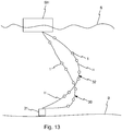
- Fig. 13 shows two scenarios.
- a fluid with high density is passed through the hose H which inter connects the ship or marine structure SH and a bottom structure 31.
- the buoyancy modules 1 are deflated. This causes the lower part of the hose H to sink towards the seabed B, forming an unfavourable J-shape.
- the hose H becomes deformed and the attachment to the bottom structure 31 becomes unfavourable due to the formation of the hose H.
- at least some of the buoyancy modules 1 are inflated, as shown in the second scenario 32, such that the lower part of the hose H is lifted and obtains its preferred shape 32 (here shown as an inverted C-shape).
- the inflated buoyancy modules 1 counteract the weight of the heavy fluid in the hose H and thus relieve the hose attachment to the bottom structure 31.
- a buoy device 1 also called a buoy clamp, which is configured to enclose a hose H during use in e.g. water
- a method can be used which includes the steps of:
- Bladder units of the described embodiments have the advantage that they can be provided with more or less fluid for different buoyancies. All hose arrangements provided with at least one buoyancy device provide the advantage of having the possibility of adjustable buoyancy. Reasons for a desire of changing the buoyancy are e.g. to move the hose towards the sea bed, thus allowing for ships to pass over it, or to adjust the shape of the hose curvature due to the fluid density inside the hose.
- the buoyancy of the hose is controlled locally or along the whole marine hose. This enhances the flexibility of the concept.
- inventive concept has been described above with reference to specific embodiments, it is not intended to be limited to the specific form set forth herein. Rather, the invention is limited only by the accompanying claims and, other embodiments than the specific above are equally possible within the scope of these appended claims. In this context, it should be mentioned that the inventive concept is not only applicable to marine hoses but also to other kinds of hoses and tubes where the buoyancy needs to be adjusted.
Landscapes
- Engineering & Computer Science (AREA)
- General Engineering & Computer Science (AREA)
- Mechanical Engineering (AREA)
- Rigid Pipes And Flexible Pipes (AREA)
Applications Claiming Priority (2)
| Application Number | Priority Date | Filing Date | Title |
|---|---|---|---|
| EP15290040 | 2015-02-24 | ||
| PCT/EP2016/053870 WO2016135197A1 (en) | 2015-02-24 | 2016-02-24 | Adjustable buoyancy clamp for hose |
Publications (2)
| Publication Number | Publication Date |
|---|---|
| EP3261915A1 EP3261915A1 (en) | 2018-01-03 |
| EP3261915B1 true EP3261915B1 (en) | 2019-10-02 |
Family
ID=52672217
Family Applications (1)
| Application Number | Title | Priority Date | Filing Date |
|---|---|---|---|
| EP16707060.6A Active EP3261915B1 (en) | 2015-02-24 | 2016-02-24 | Adjustable buoyancy clamp for hose |
Country Status (3)
| Country | Link |
|---|---|
| EP (1) | EP3261915B1 (https=) |
| JP (2) | JP2018507132A (https=) |
| WO (1) | WO2016135197A1 (https=) |
Families Citing this family (3)
| Publication number | Priority date | Publication date | Assignee | Title |
|---|---|---|---|---|
| US20190195025A1 (en) * | 2017-12-22 | 2019-06-27 | Ge Oil & Gas Uk Limited | Apparatus and method |
| KR102615774B1 (ko) * | 2021-03-25 | 2023-12-20 | 남철우 | 그물 식별용 깃발 고정부표 |
| WO2023031219A1 (en) * | 2021-08-30 | 2023-03-09 | Nederlandse Organisatie Voor Toegepast-Natuurwetenschappelijk Onderzoek Tno | Subsea activated protection system |
Family Cites Families (11)
| Publication number | Priority date | Publication date | Assignee | Title |
|---|---|---|---|---|
| GB965270A (en) * | 1961-11-17 | 1964-07-29 | Firestone Burleigh Marine Pneu | Fenders for hoses, pipes or cables and the like |
| JPS4613405Y1 (https=) * | 1967-12-07 | 1971-05-13 | ||
| FR2284512A1 (fr) * | 1974-07-26 | 1976-04-09 | Bvs | Bouee a portance constante |
| CA1001905A (en) * | 1975-06-24 | 1976-12-21 | H.B. Contracting Ltd. | Buoyancy apparatus |
| US4159189A (en) * | 1977-09-30 | 1979-06-26 | Foster Robert D | Tie-in method and apparatus |
| JPS62287900A (ja) * | 1986-05-27 | 1987-12-14 | 株式会社ブリヂストン | 物流用浮沈ホ−ス |
| NL9400517A (nl) * | 1994-03-31 | 1995-11-01 | Allseas Eng Bv | Werkwijze en inrichting voor het leggen van een pijpleiding op een onder water gelegen bodem. |
| EP0981002A1 (en) * | 1998-08-20 | 2000-02-23 | Bogey Venlo B.V. | System for controlled lowering of a tube or cable |
| GB0706989D0 (en) * | 2007-04-11 | 2007-05-16 | Balmoral Group | Device |
| JP5078756B2 (ja) * | 2008-05-29 | 2012-11-21 | 横浜ゴム株式会社 | 流体搬送用ホース |
| CN201651546U (zh) * | 2010-03-11 | 2010-11-24 | 黄福洪 | 管道稳管压重袋 |
-
2016
- 2016-02-24 EP EP16707060.6A patent/EP3261915B1/en active Active
- 2016-02-24 JP JP2017538424A patent/JP2018507132A/ja active Pending
- 2016-02-24 WO PCT/EP2016/053870 patent/WO2016135197A1/en not_active Ceased
-
2021
- 2021-02-04 JP JP2021016394A patent/JP2021073136A/ja active Pending
Non-Patent Citations (1)
| Title |
|---|
| None * |
Also Published As
| Publication number | Publication date |
|---|---|
| EP3261915A1 (en) | 2018-01-03 |
| JP2018507132A (ja) | 2018-03-15 |
| JP2021073136A (ja) | 2021-05-13 |
| WO2016135197A1 (en) | 2016-09-01 |
Similar Documents
| Publication | Publication Date | Title |
|---|---|---|
| EP2721700B1 (en) | Cable pull-in system with inflatable sealing section | |
| WO2001041549A2 (en) | Collapsible buoyancy device for risers on offshore structures | |
| EP1104524B1 (en) | System for controlled lowering of a tube or cable | |
| US20050063788A1 (en) | Riser and method of installing same | |
| US4263004A (en) | Device for transferring a fluid through a liquid body by means of a flexible pipe | |
| EP3261915B1 (en) | Adjustable buoyancy clamp for hose | |
| CN103619699A (zh) | 浮力元件、包括浮力元件的上升管组件以及支承上升管的方法 | |
| KR20140102111A (ko) | 잠수식 부교를 이용한 계류장치 | |
| US9809942B2 (en) | On-board re-inflatable containment boom and control system | |
| US6269761B1 (en) | Buoyancy device | |
| US3311132A (en) | Liquid conveying pipes | |
| AU765053B2 (en) | A buoyancy device | |
| GB2206144A (en) | Underwater oil production | |
| CN107406127B (zh) | 用于在第一船舶与第二船舶之间传递流体的方法和组件 | |
| KR101711501B1 (ko) | 라이저용 플렉시블 튜브 | |
| JP2018507132A5 (https=) | ||
| EP2398695B1 (en) | Deep water and ultra deep water mooring system | |
| EP3303709B1 (en) | On-board re-inflatable containment boom system and method | |
| KR102043323B1 (ko) | 선박 자세 제어 시스템 | |
| GB2533123A (en) | Composite component deployment configurations | |
| GB2591786A (en) | Flexible-elongate-element clamp | |
| KR102297870B1 (ko) | 유체 이송 시스템 | |
| WO2002072416A1 (en) | A buoyancy device | |
| KR20200043860A (ko) | 예인선 | |
| US20160083051A1 (en) | Arc Loading System |
Legal Events
| Date | Code | Title | Description |
|---|---|---|---|
| STAA | Information on the status of an ep patent application or granted ep patent |
Free format text: STATUS: THE INTERNATIONAL PUBLICATION HAS BEEN MADE |
|
| PUAI | Public reference made under article 153(3) epc to a published international application that has entered the european phase |
Free format text: ORIGINAL CODE: 0009012 |
|
| STAA | Information on the status of an ep patent application or granted ep patent |
Free format text: STATUS: REQUEST FOR EXAMINATION WAS MADE |
|
| 17P | Request for examination filed |
Effective date: 20170919 |
|
| AK | Designated contracting states |
Kind code of ref document: A1 Designated state(s): AL AT BE BG CH CY CZ DE DK EE ES FI FR GB GR HR HU IE IS IT LI LT LU LV MC MK MT NL NO PL PT RO RS SE SI SK SM TR |
|
| AX | Request for extension of the european patent |
Extension state: BA ME |
|
| DAV | Request for validation of the european patent (deleted) | ||
| DAX | Request for extension of the european patent (deleted) | ||
| GRAP | Despatch of communication of intention to grant a patent |
Free format text: ORIGINAL CODE: EPIDOSNIGR1 |
|
| STAA | Information on the status of an ep patent application or granted ep patent |
Free format text: STATUS: GRANT OF PATENT IS INTENDED |
|
| INTG | Intention to grant announced |
Effective date: 20190426 |
|
| GRAS | Grant fee paid |
Free format text: ORIGINAL CODE: EPIDOSNIGR3 |
|
| GRAA | (expected) grant |
Free format text: ORIGINAL CODE: 0009210 |
|
| STAA | Information on the status of an ep patent application or granted ep patent |
Free format text: STATUS: THE PATENT HAS BEEN GRANTED |
|
| AK | Designated contracting states |
Kind code of ref document: B1 Designated state(s): AL AT BE BG CH CY CZ DE DK EE ES FI FR GB GR HR HU IE IS IT LI LT LU LV MC MK MT NL NO PL PT RO RS SE SI SK SM TR |
|
| REG | Reference to a national code |
Ref country code: GB Ref legal event code: FG4D |
|
| REG | Reference to a national code |
Ref country code: AT Ref legal event code: REF Ref document number: 1185891 Country of ref document: AT Kind code of ref document: T Effective date: 20191015 Ref country code: CH Ref legal event code: EP |
|
| REG | Reference to a national code |
Ref country code: DE Ref legal event code: R096 Ref document number: 602016021634 Country of ref document: DE |
|
| REG | Reference to a national code |
Ref country code: IE Ref legal event code: FG4D |
|
| REG | Reference to a national code |
Ref country code: NL Ref legal event code: FP |
|
| REG | Reference to a national code |
Ref country code: NO Ref legal event code: T2 Effective date: 20191002 |
|
| REG | Reference to a national code |
Ref country code: LT Ref legal event code: MG4D |
|
| REG | Reference to a national code |
Ref country code: AT Ref legal event code: MK05 Ref document number: 1185891 Country of ref document: AT Kind code of ref document: T Effective date: 20191002 |
|
| PG25 | Lapsed in a contracting state [announced via postgrant information from national office to epo] |
Ref country code: LV Free format text: LAPSE BECAUSE OF FAILURE TO SUBMIT A TRANSLATION OF THE DESCRIPTION OR TO PAY THE FEE WITHIN THE PRESCRIBED TIME-LIMIT Effective date: 20191002 Ref country code: SE Free format text: LAPSE BECAUSE OF FAILURE TO SUBMIT A TRANSLATION OF THE DESCRIPTION OR TO PAY THE FEE WITHIN THE PRESCRIBED TIME-LIMIT Effective date: 20191002 Ref country code: FI Free format text: LAPSE BECAUSE OF FAILURE TO SUBMIT A TRANSLATION OF THE DESCRIPTION OR TO PAY THE FEE WITHIN THE PRESCRIBED TIME-LIMIT Effective date: 20191002 Ref country code: BG Free format text: LAPSE BECAUSE OF FAILURE TO SUBMIT A TRANSLATION OF THE DESCRIPTION OR TO PAY THE FEE WITHIN THE PRESCRIBED TIME-LIMIT Effective date: 20200102 Ref country code: PT Free format text: LAPSE BECAUSE OF FAILURE TO SUBMIT A TRANSLATION OF THE DESCRIPTION OR TO PAY THE FEE WITHIN THE PRESCRIBED TIME-LIMIT Effective date: 20200203 Ref country code: ES Free format text: LAPSE BECAUSE OF FAILURE TO SUBMIT A TRANSLATION OF THE DESCRIPTION OR TO PAY THE FEE WITHIN THE PRESCRIBED TIME-LIMIT Effective date: 20191002 Ref country code: GR Free format text: LAPSE BECAUSE OF FAILURE TO SUBMIT A TRANSLATION OF THE DESCRIPTION OR TO PAY THE FEE WITHIN THE PRESCRIBED TIME-LIMIT Effective date: 20200103 Ref country code: PL Free format text: LAPSE BECAUSE OF FAILURE TO SUBMIT A TRANSLATION OF THE DESCRIPTION OR TO PAY THE FEE WITHIN THE PRESCRIBED TIME-LIMIT Effective date: 20191002 Ref country code: LT Free format text: LAPSE BECAUSE OF FAILURE TO SUBMIT A TRANSLATION OF THE DESCRIPTION OR TO PAY THE FEE WITHIN THE PRESCRIBED TIME-LIMIT Effective date: 20191002 Ref country code: AT Free format text: LAPSE BECAUSE OF FAILURE TO SUBMIT A TRANSLATION OF THE DESCRIPTION OR TO PAY THE FEE WITHIN THE PRESCRIBED TIME-LIMIT Effective date: 20191002 |
|
| PGFP | Annual fee paid to national office [announced via postgrant information from national office to epo] |
Ref country code: NO Payment date: 20200210 Year of fee payment: 5 |
|
| PG25 | Lapsed in a contracting state [announced via postgrant information from national office to epo] |
Ref country code: CZ Free format text: LAPSE BECAUSE OF FAILURE TO SUBMIT A TRANSLATION OF THE DESCRIPTION OR TO PAY THE FEE WITHIN THE PRESCRIBED TIME-LIMIT Effective date: 20191002 Ref country code: RS Free format text: LAPSE BECAUSE OF FAILURE TO SUBMIT A TRANSLATION OF THE DESCRIPTION OR TO PAY THE FEE WITHIN THE PRESCRIBED TIME-LIMIT Effective date: 20191002 Ref country code: HR Free format text: LAPSE BECAUSE OF FAILURE TO SUBMIT A TRANSLATION OF THE DESCRIPTION OR TO PAY THE FEE WITHIN THE PRESCRIBED TIME-LIMIT Effective date: 20191002 Ref country code: IS Free format text: LAPSE BECAUSE OF FAILURE TO SUBMIT A TRANSLATION OF THE DESCRIPTION OR TO PAY THE FEE WITHIN THE PRESCRIBED TIME-LIMIT Effective date: 20200224 |
|
| PG25 | Lapsed in a contracting state [announced via postgrant information from national office to epo] |
Ref country code: AL Free format text: LAPSE BECAUSE OF FAILURE TO SUBMIT A TRANSLATION OF THE DESCRIPTION OR TO PAY THE FEE WITHIN THE PRESCRIBED TIME-LIMIT Effective date: 20191002 |
|
| REG | Reference to a national code |
Ref country code: DE Ref legal event code: R097 Ref document number: 602016021634 Country of ref document: DE |
|
| PG2D | Information on lapse in contracting state deleted |
Ref country code: IS |
|
| PG25 | Lapsed in a contracting state [announced via postgrant information from national office to epo] |
Ref country code: IS Free format text: LAPSE BECAUSE OF FAILURE TO SUBMIT A TRANSLATION OF THE DESCRIPTION OR TO PAY THE FEE WITHIN THE PRESCRIBED TIME-LIMIT Effective date: 20200202 Ref country code: EE Free format text: LAPSE BECAUSE OF FAILURE TO SUBMIT A TRANSLATION OF THE DESCRIPTION OR TO PAY THE FEE WITHIN THE PRESCRIBED TIME-LIMIT Effective date: 20191002 Ref country code: DK Free format text: LAPSE BECAUSE OF FAILURE TO SUBMIT A TRANSLATION OF THE DESCRIPTION OR TO PAY THE FEE WITHIN THE PRESCRIBED TIME-LIMIT Effective date: 20191002 Ref country code: RO Free format text: LAPSE BECAUSE OF FAILURE TO SUBMIT A TRANSLATION OF THE DESCRIPTION OR TO PAY THE FEE WITHIN THE PRESCRIBED TIME-LIMIT Effective date: 20191002 |
|
| PLBE | No opposition filed within time limit |
Free format text: ORIGINAL CODE: 0009261 |
|
| STAA | Information on the status of an ep patent application or granted ep patent |
Free format text: STATUS: NO OPPOSITION FILED WITHIN TIME LIMIT |
|
| PG25 | Lapsed in a contracting state [announced via postgrant information from national office to epo] |
Ref country code: SM Free format text: LAPSE BECAUSE OF FAILURE TO SUBMIT A TRANSLATION OF THE DESCRIPTION OR TO PAY THE FEE WITHIN THE PRESCRIBED TIME-LIMIT Effective date: 20191002 Ref country code: SK Free format text: LAPSE BECAUSE OF FAILURE TO SUBMIT A TRANSLATION OF THE DESCRIPTION OR TO PAY THE FEE WITHIN THE PRESCRIBED TIME-LIMIT Effective date: 20191002 |
|
| 26N | No opposition filed |
Effective date: 20200703 |
|
| REG | Reference to a national code |
Ref country code: CH Ref legal event code: PL |
|
| REG | Reference to a national code |
Ref country code: BE Ref legal event code: MM Effective date: 20200229 |
|
| PG25 | Lapsed in a contracting state [announced via postgrant information from national office to epo] |
Ref country code: LU Free format text: LAPSE BECAUSE OF NON-PAYMENT OF DUE FEES Effective date: 20200224 Ref country code: MC Free format text: LAPSE BECAUSE OF FAILURE TO SUBMIT A TRANSLATION OF THE DESCRIPTION OR TO PAY THE FEE WITHIN THE PRESCRIBED TIME-LIMIT Effective date: 20191002 |
|
| PG25 | Lapsed in a contracting state [announced via postgrant information from national office to epo] |
Ref country code: CH Free format text: LAPSE BECAUSE OF NON-PAYMENT OF DUE FEES Effective date: 20200229 Ref country code: LI Free format text: LAPSE BECAUSE OF NON-PAYMENT OF DUE FEES Effective date: 20200229 Ref country code: SI Free format text: LAPSE BECAUSE OF FAILURE TO SUBMIT A TRANSLATION OF THE DESCRIPTION OR TO PAY THE FEE WITHIN THE PRESCRIBED TIME-LIMIT Effective date: 20191002 |
|
| PG25 | Lapsed in a contracting state [announced via postgrant information from national office to epo] |
Ref country code: IE Free format text: LAPSE BECAUSE OF NON-PAYMENT OF DUE FEES Effective date: 20200224 |
|
| PG25 | Lapsed in a contracting state [announced via postgrant information from national office to epo] |
Ref country code: BE Free format text: LAPSE BECAUSE OF NON-PAYMENT OF DUE FEES Effective date: 20200229 |
|
| PGFP | Annual fee paid to national office [announced via postgrant information from national office to epo] |
Ref country code: IT Payment date: 20210209 Year of fee payment: 6 Ref country code: FR Payment date: 20210218 Year of fee payment: 6 Ref country code: NL Payment date: 20210203 Year of fee payment: 6 |
|
| PGFP | Annual fee paid to national office [announced via postgrant information from national office to epo] |
Ref country code: GB Payment date: 20210211 Year of fee payment: 6 Ref country code: DE Payment date: 20210223 Year of fee payment: 6 |
|
| REG | Reference to a national code |
Ref country code: NO Ref legal event code: MMEP |
|
| PG25 | Lapsed in a contracting state [announced via postgrant information from national office to epo] |
Ref country code: NO Free format text: LAPSE BECAUSE OF NON-PAYMENT OF DUE FEES Effective date: 20210228 |
|
| PG25 | Lapsed in a contracting state [announced via postgrant information from national office to epo] |
Ref country code: TR Free format text: LAPSE BECAUSE OF FAILURE TO SUBMIT A TRANSLATION OF THE DESCRIPTION OR TO PAY THE FEE WITHIN THE PRESCRIBED TIME-LIMIT Effective date: 20191002 Ref country code: MT Free format text: LAPSE BECAUSE OF FAILURE TO SUBMIT A TRANSLATION OF THE DESCRIPTION OR TO PAY THE FEE WITHIN THE PRESCRIBED TIME-LIMIT Effective date: 20191002 Ref country code: CY Free format text: LAPSE BECAUSE OF FAILURE TO SUBMIT A TRANSLATION OF THE DESCRIPTION OR TO PAY THE FEE WITHIN THE PRESCRIBED TIME-LIMIT Effective date: 20191002 |
|
| PG25 | Lapsed in a contracting state [announced via postgrant information from national office to epo] |
Ref country code: MK Free format text: LAPSE BECAUSE OF FAILURE TO SUBMIT A TRANSLATION OF THE DESCRIPTION OR TO PAY THE FEE WITHIN THE PRESCRIBED TIME-LIMIT Effective date: 20191002 |
|
| REG | Reference to a national code |
Ref country code: DE Ref legal event code: R119 Ref document number: 602016021634 Country of ref document: DE |
|
| REG | Reference to a national code |
Ref country code: NL Ref legal event code: MM Effective date: 20220301 |
|
| GBPC | Gb: european patent ceased through non-payment of renewal fee |
Effective date: 20220224 |
|
| PG25 | Lapsed in a contracting state [announced via postgrant information from national office to epo] |
Ref country code: NL Free format text: LAPSE BECAUSE OF NON-PAYMENT OF DUE FEES Effective date: 20220301 Ref country code: FR Free format text: LAPSE BECAUSE OF NON-PAYMENT OF DUE FEES Effective date: 20220228 |
|
| PG25 | Lapsed in a contracting state [announced via postgrant information from national office to epo] |
Ref country code: GB Free format text: LAPSE BECAUSE OF NON-PAYMENT OF DUE FEES Effective date: 20220224 Ref country code: DE Free format text: LAPSE BECAUSE OF NON-PAYMENT OF DUE FEES Effective date: 20220901 |
|
| PG25 | Lapsed in a contracting state [announced via postgrant information from national office to epo] |
Ref country code: IT Free format text: LAPSE BECAUSE OF NON-PAYMENT OF DUE FEES Effective date: 20220224 |
|
| P01 | Opt-out of the competence of the unified patent court (upc) registered |
Effective date: 20230528 |