EP3261227A1 - Stator core and stator core production method - Google Patents
Stator core and stator core production method Download PDFInfo
- Publication number
- EP3261227A1 EP3261227A1 EP16780147.1A EP16780147A EP3261227A1 EP 3261227 A1 EP3261227 A1 EP 3261227A1 EP 16780147 A EP16780147 A EP 16780147A EP 3261227 A1 EP3261227 A1 EP 3261227A1
- Authority
- EP
- European Patent Office
- Prior art keywords
- concentric coil
- axial end
- peripheral surface
- stator core
- slot
- Prior art date
- Legal status (The legal status is an assumption and is not a legal conclusion. Google has not performed a legal analysis and makes no representation as to the accuracy of the status listed.)
- Granted
Links
Images




Classifications
-
- H—ELECTRICITY
- H02—GENERATION; CONVERSION OR DISTRIBUTION OF ELECTRIC POWER
- H02K—DYNAMO-ELECTRIC MACHINES
- H02K3/00—Details of windings
- H02K3/46—Fastening of windings on the stator or rotor structure
- H02K3/48—Fastening of windings on the stator or rotor structure in slots
-
- H—ELECTRICITY
- H02—GENERATION; CONVERSION OR DISTRIBUTION OF ELECTRIC POWER
- H02K—DYNAMO-ELECTRIC MACHINES
- H02K1/00—Details of the magnetic circuit
- H02K1/06—Details of the magnetic circuit characterised by the shape, form or construction
- H02K1/12—Stationary parts of the magnetic circuit
- H02K1/16—Stator cores with slots for windings
- H02K1/165—Shape, form or location of the slots
-
- H—ELECTRICITY
- H02—GENERATION; CONVERSION OR DISTRIBUTION OF ELECTRIC POWER
- H02K—DYNAMO-ELECTRIC MACHINES
- H02K15/00—Processes or apparatus specially adapted for manufacturing, assembling, maintaining or repairing of dynamo-electric machines
- H02K15/06—Embedding prefabricated windings in the machines
- H02K15/062—Windings in slots; Salient pole windings
- H02K15/065—Windings consisting of complete sections, e.g. coils or waves
- H02K15/066—Windings consisting of complete sections, e.g. coils or waves inserted perpendicularly to the axis of the slots or inter-polar channels
-
- H—ELECTRICITY
- H02—GENERATION; CONVERSION OR DISTRIBUTION OF ELECTRIC POWER
- H02K—DYNAMO-ELECTRIC MACHINES
- H02K15/00—Processes or apparatus specially adapted for manufacturing, assembling, maintaining or repairing of dynamo-electric machines
- H02K15/08—Forming windings by laying conductors into or around core parts
- H02K15/085—Forming windings by laying conductors into or around core parts by laying conductors into slotted stators
-
- H—ELECTRICITY
- H02—GENERATION; CONVERSION OR DISTRIBUTION OF ELECTRIC POWER
- H02K—DYNAMO-ELECTRIC MACHINES
- H02K15/00—Processes or apparatus specially adapted for manufacturing, assembling, maintaining or repairing of dynamo-electric machines
- H02K15/12—Impregnating, moulding insulation, heating or drying of windings, stators, rotors or machines
-
- H—ELECTRICITY
- H02—GENERATION; CONVERSION OR DISTRIBUTION OF ELECTRIC POWER
- H02K—DYNAMO-ELECTRIC MACHINES
- H02K3/00—Details of windings
- H02K3/04—Windings characterised by the conductor shape, form or construction, e.g. with bar conductors
- H02K3/12—Windings characterised by the conductor shape, form or construction, e.g. with bar conductors arranged in slots
-
- H—ELECTRICITY
- H02—GENERATION; CONVERSION OR DISTRIBUTION OF ELECTRIC POWER
- H02K—DYNAMO-ELECTRIC MACHINES
- H02K3/00—Details of windings
- H02K3/32—Windings characterised by the shape, form or construction of the insulation
- H02K3/34—Windings characterised by the shape, form or construction of the insulation between conductors or between conductor and core, e.g. slot insulation
-
- H—ELECTRICITY
- H02—GENERATION; CONVERSION OR DISTRIBUTION OF ELECTRIC POWER
- H02K—DYNAMO-ELECTRIC MACHINES
- H02K15/00—Processes or apparatus specially adapted for manufacturing, assembling, maintaining or repairing of dynamo-electric machines
- H02K15/20—Shaping or compacting conductors or winding heads after the installation of the winding in the cores or machines; Applying fastening means on winding heads
- H02K15/22—Shaping or compacting conductors in slots or around salient poles
Definitions
- the present invention relates to stator cores and methods for manufacturing the same.
- tubular clearances that cause capillary action are less likely to be formed in a coil end projecting from a stator core. Capillary action is therefore less likely to occur in coils made of a rectangular wire.
- Patent Document 1 International Publication No. 2014/020755 ( WO 2014/020755 )
- WO 2014/020755 does not disclose impregnation with varnish for coils made of a rectangular wire.
- the present invention was developed in order to solve such a problem as described above, and it is one object of the present invention to provide a stator core and a method for manufacturing the same, in which, even in the case of using a coil made of a rectangular wire, slots can be sufficiently filled with a fixing agent and the coil can be fixed firmly.
- a stator core includes: a stator core including a plurality of teeth and a plurality of slots each located between adjacent ones of the teeth; and a concentric coil formed by concentrically winding a rectangular wire and placed in the slots of the stator core.
- An interval in a circumferential direction of the stator core between an outer peripheral surface of an axial end of a slot accommodated portion of the concentric coil about a winding center of the concentric coil and the tooth facing the outer peripheral surface is larger than an interval in the circumferential direction of the stator core between an inner peripheral surface of the axial end of the slot accommodated portion of the concentric coil about the winding center of the concentric coil and the tooth facing the inner peripheral surface.
- the interval in the circumferential direction of the stator core between the outer peripheral surface of the axial end of the slot accommodated portion of the concentric coil about the winding center of the concentric coil and the tooth facing the outer peripheral surface is larger than the interval in the circumferential direction of the stator core between the inner peripheral surface of the axial end of the slot accommodated portion of the concentric coil about the winding center of the concentric coil and the tooth facing the inner peripheral surface.
- the fixing agent can be easily guided into the slot when flowing along the outer peripheral surface of the concentric coil, because of the large interval (clearance) in the circumferential direction between the outer peripheral surface of the axial end of the slot accommodated portion and the tooth.
- the slots can be sufficiently filled with the fixing agent and the coil can be fixed firmly.
- a method for manufacturing a stator core according to a second aspect of the present invention is a method for manufacturing a stator core including a stator core including a plurality of teeth and a plurality of slots each located between adjacent ones of the teeth, and a concentric coil formed by concentrically winding a rectangular wire and placed in the slots of the stator core.
- the method includes the steps of: placing the concentric coil in the slots so that an interval in a circumferential direction of the stator core between an outer peripheral surface of an axial end of a slot accommodated portion of the concentric coil about a winding center of the concentric coil and the tooth facing the outer peripheral surface is larger than an interval in the circumferential direction of the stator core between an inner peripheral surface of the axial end of the slot accommodated portion of the concentric coil about the winding center of the concentric coil and the tooth facing the inner peripheral surface; and with the stator core being placed so that its axial end face faces upward, supplying a fixing agent so that the fixing agent flows along the outer peripheral surface of the concentric coil, thereby filling the slots with the fixing agent.
- the method for manufacturing a stator core according to the second aspect of the present invention includes the step of: placing the concentric coil in the slots so that the interval in the circumferential direction of the stator core between the outer peripheral surface of the axial end of the slot accommodated portion of the concentric coil about the winding center of the concentric coil and the tooth facing the outer peripheral surface is larger than the interval in the circumferential direction of the stator core between the inner peripheral surface of the axial end of the slot accommodated portion of the concentric coil about the winding center of the concentric coil and the tooth facing the inner peripheral surface.
- the fixing agent can be easily guided into the slot when flowing along the outer peripheral surface of the concentric coil, because of the large interval (clearance) in the circumferential direction between the outer peripheral surface of the axial end of the slot accommodated portion and the tooth.
- a method for manufacturing a stator core can be provided in which, even in the case of using a coil made of a rectangular wire, the slots can be sufficiently filled with the fixing agent and the coil can be fixed firmly.
- the slots can be sufficiently filled with the fixing agent and the coil can be fixed firmly.
- FIGS. 2 to 5 and 11 and FIG. 12 showing a second embodiment are schematic views of an annular stator core 20 laid out flat, showing the radially inner side of the stator core 20 as viewed from the central axis of rotation of a rotor core 10.
- the rotating electrical machine 100 includes the rotor core 10.
- the rotor core 10 is provided with a plurality of permanent magnets 11.
- the plurality of permanent magnets 11 are arranged at substantially regular angular intervals in the circumferential direction.
- the rotating electrical machine 100 further includes the stator core 20 disposed so as to face the rotor core 10 in the radial direction.
- the stator core 20 includes a plurality of teeth 21 and a plurality of slots 22 each located between adjacent ones of the teeth 21.
- Concentric coils 30 each formed by concentrically winding a rectangular wire are placed in the slots 22 of the stator core 20.
- FIG. 2 shows a single concentric coil 30 placed in the slots 22 of the stator core 20.
- the concentric coil 30 has a substantially symmetrical shape with respect to an axis C1 passing through the center of the concentric coil 30 in the Z direction, so that the X1 direction side and the X2 direction side of the concentric coil 30 are mirror images of each other.
- the structure of the X1 direction side of the concentric coil 30 will be described below.
- the concentric coil 30 is a coil formed by concentrically winding a rectangular wire and is placed in the slots 22 of the stator core 20.
- an interval L1 in the circumferential direction of the stator core 20 between an outer peripheral surface 32 of an axial end 31 of a slot accommodated portion 36 of the concentric coil 30 about the winding center C of the concentric coil 30 and the tooth 21 facing the outer peripheral surface 32 is larger than an interval L2 in the circumferential direction of the stator core 20 between an inner peripheral surface 33 of the axial end 31 of the slot accommodated portion 36 of the concentric coil 30 about the winding center C of the concentric coil 30 and the tooth 21 facing the inner peripheral surface 33.
- the winding center C is the middle in the circumferential direction (X direction) between a pair of slot accommodated portions 36 of the concentric coil 30 and the middle in the axial direction (Z direction) between a pair of coil end portions 35 of the concentric coil 30 excluding lead portions, not shown.
- the lead portions are one end and the other end of the rectangular wire forming the concentric coil 30.
- the lead portions function as a power line for connection to an external circuit such as a power supply, a neutral line for connection to a connection point (neutral point) to a concentric coil 30 of another phase, etc.
- insulating paper 23 is placed between the concentric coil 30 and the slot 22.
- the inner peripheral surface 33 of the axial end 31 contacts the insulating paper 23.
- the axial end 31 and the tooth 21 (axial end 21a) located on the side (X2 direction side) facing the inner peripheral surface 33 of the axial end 31 are separated by the interval L2 in the circumferential direction which corresponds to the thickness t of the insulating paper 23.
- the insulating paper 23 is one example of the "insulating member.”
- the interval L1 in the circumferential direction between each of the axial ends 31 (axial ends 311, 312) of the concentric coil 30 which are located at both ends on one side (Z1 direction side) and the other side (Z2 direction side) in the axial direction (Z direction) of the slot 22 and the tooth 21 (each axial end 21a) located on the side (X1 direction side) facing the outer peripheral surface 32 of the axial end 31 is larger than the interval L2 in the circumferential direction between each of the axial ends 31 (axial ends 311, 312) and the tooth 21 (each axial end 21a) located on the side (X2 direction side) facing the inner peripheral surface 33 of the axial end 31.
- the interval L1 in the circumferential direction between the concentric coil 30 and the tooth 21 (corresponding portion 21b) on the side (X1 direction side) facing the outer peripheral surface 32 of the concentric coil 30 gradually decreases from an axial end 22a of the slot 22 toward an axial middle portion 22b of the slot 22.
- the interval L1 in the circumferential direction between the concentric coil 30 and the tooth 21 (corresponding portion 21b) facing the outer peripheral surface 32 of the concentric coil 30 gradually decreases from the axial end 22a of the slot 22 and toward the vicinity of the axial middle portion 22b of the slot 22 so that the interval L1 in the circumferential direction between the concentric coil 30 and the tooth 21 (corresponding portion 21b) becomes the smallest in the vicinity of the axial middle portion 22b of the slot 22.
- the outer peripheral surface 32 of the concentric coil 30 and the insulating paper 23 are in contact with each other in the vicinity of the axial middle portion 22b of the slot 22.
- the concentric coil 30 has a substantially symmetrical shape with respect to an axis C2 passing through the center of the concentric coil 30 in the X direction, so that the Z1 direction side and the Z2 direction side of the concentric coil 30 are mirror images of each other. That is, in both of the axial end 311 and the axial end 312, the interval L1 in the circumferential direction between the concentric coil 30 and the tooth 21 (corresponding portion 21b) on the side (X1 direction side) facing the outer peripheral surface 32 of the concentric coil 30 gradually decreases from the axial end 22a of the slot 22 toward the axial middle portion 22b (the vicinity of the axial middle portion 22b) of the slot 22.
- the concentric coil 30 is placed in the slot 22 such that the axial ends 31 (311, 312) of the concentric coil 30 which are located at the axial ends 22a of the slot 22 are located closer to the axis C1 of the concentric coil 30.
- the concentric coil 30 is placed in the slot 22 such that a coil portion 313 of the concentric coil 30 which is located in the vicinity of the axial middle portion 22b of the slot 22 is located farther away from the axis C1 of the concentric coil 30.
- the concentric coils 30 include a first concentric coil 30a and a second concentric coil 30b which are placed in the same slot 22 located between a first tooth 211 and a second tooth 212 which are adjacent to each other.
- An outer peripheral surface 32a of a first axial end 31a of a slot accommodated portion 36 of the first concentric coil 30a about the winding center C of the concentric coil 30 faces the first tooth 211, and an outer peripheral surface 32b of a second axial end 31b of a slot accommodated portion 36 of the second concentric coil 30b about the winding center C of the concentric coil 30 faces the second tooth 212.
- an interval L11 in the circumferential direction between the first axial end 31a of the first concentric coil 30a and an axial end 211a of the first tooth 211 facing the outer peripheral surface 32a of the first axial end 31a of the first concentric coil 30a is larger than an interval L21 in the circumferential direction between the first axial end 31 a of the first concentric coil 30a and an axial end 212a of the second tooth 212 facing an inner peripheral surface 33a of the first axial end 31a.
- the interval L11 is equal to the interval L1
- the interval L21 is equal to the interval L2.
- An interval L12 in the circumferential direction between the axial end 31b of the second concentric coil 30b and the axial end 212a of the second tooth 212 facing the outer peripheral surface 32b of the second axial end 31b of the second concentric coil 30b is larger than an interval L22 in the circumferential direction between the second axial end 31b of the second concentric coil 30b and the axial end 211a of the first tooth 211 facing an inner peripheral surface 33b of the second axial end 31b.
- the interval L12 is equal to the interval L1
- the interval L22 is equal to the interval L2.
- the first concentric coil 30a and the second concentric coil 30b are formed by concentrically winding a rectangular wire 34a and a rectangular wire 34b into a plurality of turns.
- the turns of the rectangular wire 34a of the first concentric coil 30a and the turns of the rectangular wire 34b of the second concentric coil 30b are alternately arranged at intervals L3 in the radial direction.
- the turns of the rectangular wire 34a of the first concentric coil 30a are placed on the X2 direction side of the slot 22, and the turns of the rectangular wire 34b of the second concentric coil 30b are placed on the X1 direction side of the slot 22.
- the turns of the rectangular wire 34a of the first concentric coil 30a are placed on the X1 direction side of the slot 22, and the turns of the rectangular wire 34b of the second concentric coil 30b are placed on the X2 direction side of the slot 22.
- the turns of the rectangular wire 34a of the first concentric coil 30a and the turns of the rectangular wire 34b of the second concentric coil 30b are arranged so as to cross each other in the slot 22 as viewed from the radially inner side of the stator core 20.
- Varnish 40 filling the slots 22 will be described with reference to FIG. 3 and 5 to 7 .
- the varnish 40 filling the slots 22 is not shown in FIGS. 1, 2 , and 4 .
- the varnish 40 is one example of the "fixing agent.”
- the varnish 40 fills between each concentric coil 30 and the insulating paper 34 placed in the slot 22. That is, in the first embodiment, as shown in FIG. 3 , the varnish 40 fills between the axial end 31 of the slot accommodated portion 36 and the tooth 21 facing the outer peripheral surface 32 of the axial end 31 and between the axial end 31 of the slot accommodated portion 36 and the tooth 21 facing the inner peripheral surface 33 of the axial end 31. As shown in FIGS. 6 and 7 , the varnish 40 fills between each turn of the rectangular wire 34a of the first concentric coil 30a and each turn of the rectangular wire 34b of the second concentric coil 30b which face each other in the radial direction.
- the first embodiment has the following effects.
- the interval L1 in the circumferential direction of the stator core 20 between the outer peripheral surface 32 of the axial end 31 of the slot accommodated portion 36 of the concentric coil 30 about the winding center of the concentric coil 30 and the tooth 21 facing the outer peripheral surface 32 is larger than the interval L2 in the circumferential direction of the stator core 20 between the inner peripheral surface 33 of the axial end 31 of the slot accommodated portion 36 of the concentric coil 30 about the winding center of the concentric coil 30 and the tooth 21 facing the inner peripheral surface 33.
- the varnish 40 can be easily guided into the slot 22 when flowing along the outer peripheral surface 32 of the concentric coil 30, because the interval L1 (clearance) in the circumferential direction between the outer peripheral surface 32 of the axial end 31 and the tooth 21 is large at the axial end 21 a of the tooth 21 (the axial end 22a of the slot 22).
- the slots 22 can be sufficiently filled with the varnish 40 and the concentric coil 30 can be fixed firmly.
- the interval L1 in the circumferential direction between the concentric coil 30 and the tooth 21 (corresponding portion 21b) facing the outer peripheral surface 32 of the concentric coil 30 gradually decreases from the axial end 22a of the slot 22 toward the axial middle portion 22b of the slot 22. Accordingly, in the vicinity of the axial end 22a of the slot 22, the varnish 40 is guided into the slot 22 mainly by gravity, whereas on the axial middle portion 22b side of the slot 22, the varnish 40 is guided into the slot 22 by capillary action in addition to gravity. The slot 22 is thus smoothly filled with the varnish 40.
- the interval L1 in the circumferential direction between the concentric coil 30 and the tooth 21 (corresponding portion 21b) facing the outer peripheral surface 32 of the concentric coil 30 gradually decreases from the axial end 22a of the slot 22 toward the vicinity of the axial middle portion 22b of the slot 22 so that the interval L1 in the circumferential direction between the concentric coil 30 and the tooth 21 (corresponding portion 21b) is the smallest in the vicinity of the axial middle portion 22b of the slot 22.
- the varnish 40 flows along the axial end 31 and flows to the back surface of the axial end 31, so that the varnish 40 can smoothly fill (be guided) down to the vicinity of the axial middle portion 22b of the slot 22.
- the interval L1 in the circumferential direction between each of the axial ends 31 (311, 312) of the concentric coil 30 which are located at both ends on one side and the other side in the axial direction of the slot 22 and the tooth 21 (each axial end 21 a) facing the outer peripheral surface 32 of the axial end 31 is larger than the interval L2 in the circumferential direction between each of the axial ends 31 and the tooth 21 (each axial end 21a) facing the inner peripheral surface 33 of the axial end 31.
- the varnish 40 can thus be easily guided into the slot 22 on both the one side and the other side in the axial direction of the slot 22, whereby the slot 22 can thus be more effectively filled with the varnish 40.
- the interval L11 in the circumferential direction between the first axial end 31a of the first concentric coil 30a and the first tooth 211 (axial end 211a) facing the outer peripheral surface 32a of the first axial end 31a of the first concentric coil 30a is larger than the interval L21 in the circumferential direction between the first axial end 31a of the first concentric coil 30a and the second tooth 212 (axial end 212a) facing the inner peripheral surface 33a of the first axial end 31 a.
- the interval L12 in the circumferential direction between the second axial end 31b of the second concentric coil 30b and the second tooth 212 (axial end 212a) facing the outer peripheral surface 32b of the second axial end 31b of the second concentric coil 30b is larger than the interval L22 in the circumferential direction between the second axial end 31b of the second concentric coil 30b and the first tooth 211 (axial end 211a) facing the inner peripheral surface 33b of the second axial end 31b. Accordingly, even when the first concentric coil 30a and the second concentric coil 30b are placed in a single slot 22, the varnish 40 can be easily guided into the slot 22.
- the turns of the rectangular wire 34a of the first concentric coil 30a and the turns of the rectangular wire 34b of the second concentric coil 30b are alternately arranged at the intervals L3 in the radial direction.
- the varnish 40 thus fills between each turn of the rectangular wire 34a of the first concentric coil 30a and each turn of the rectangular wire 34b of the second concentric coil 30b, whereby the first concentric coil 30a and the second concentric coil 30b can be fixed firmly.
- the insulating paper 23 is disposed between the slot 22 and the concentric coil 30.
- the inner peripheral surface 33 of the axial end 31 is in contact with the insulating paper 23, so that the axial end 31 and the tooth 21 (axial end 21a) facing the inner peripheral surface 33 of the axial end 31 are separated by the interval L2 in the circumferential direction which corresponds to the thickness t of the insulating paper 23.
- the interval L1 in the circumferential direction between the axial end 31 located at the axial end 22a of the slot 22 and the tooth 21 (axial end 21 a) facing the outer peripheral surface 32 of the axial end 31 can be increased.
- the varnish 40 can be more easily guided into the slot 22.
- the varnish 40 fills between the axial end 31 of the slot accommodated portion 36 and the tooth 21 facing the outer peripheral surface 32 of the axial end 31 and between the axial end 31 of the slot accommodated portion 36 and the tooth 21 facing the inner peripheral surface 33 of the axial end 31. Since the varnish 40 thus fills both the outer peripheral surface 32 side and the inner peripheral surface 33 side of the axial end 31, the concentric coil 30 can be fixed more firmly. Since the varnish 40 solidifies relatively quickly, the concentric coil 30 can be fixed relatively quickly.
- FIGS. 9 and 10 show two concentric coils 30 (the first concentric coil 30a and the second concentric coil 30b) being placed in the slots 22 of the stator core 20.
- the concentric coils 30 (the first concentric coil 30a and the second concentric coil 30b) each formed by concentrically winding a rectangular wire are prepared.
- the first concentric coil 30a and the second concentric coil 30b are then attached to a jig 50 such that the turns of the rectangular wire 34a of the first concentric coil 30a and the turns of the rectangular wire 34b of the second concentric coil 30b are alternately arranged in the radial direction.
- the concentric coils 30 are placed in the slots 22 such that the interval L1 in the circumferential direction of the stator core 20 between the outer peripheral surface 32 of each axial end 31 of the slot accommodated portion 36 of the concentric coil 30 about the winding center of the concentric coil 30 and the tooth 21 facing the outer peripheral surface 32 in the circumferential direction of the stator core 20 is larger than the interval L2 in the circumferential direction of the stator core 20 between each axial end 31 and the tooth 21 facing the inner peripheral surface 33 of the axial end 31 of the slot accommodated portion 36 of the concentric coil 30 about the winding center of the concentric coil 30.
- the concentric coils 30 (the first concentric coil 30a and the second concentric coil 30b) attached to the jig 50 are pressed outward in the radial direction so as to be inserted into the slot 22.
- Each concentric coil 30 is thus gradually widened in the circumferential direction and changes from the shape shown in FIG. 8 into the shape (barrel shape) shown in FIG. 11 , namely such a shape that the inside width in the circumferential direction is large and those portions of the concentric coil 30 which are located in the slots 22 are curved along the axial direction.
- the varnish 40 is supplied from above to flow (dropped to flow down) along the outer peripheral surfaces 32 of the concentric coils 30, whereby the slots 22 are filled with the varnish 40.
- the varnish 40 is dropped onto the coil ends 35 from a varnish dropping device 41.
- the varnish 40 thus flows along the outer peripheral surfaces 32 of the concentric coils 30 (coil ends 35) into the slots 22.
- the varnish 40 is guided into the slot 22 mainly by gravity, whereas on the axial middle portion 22b side of each slot 22, the varnish 40 is guided into the slot 22 by capillary action in addition to gravity.
- the varnish 40 is dropped on each side of the stator core 20, namely on one side (Z1 direction side) and the other side (Z2 direction side) of the stator core 20.
- the stator core 20 may be rotated 360 degrees, or if the varnish 40 is not sufficiently dropped onto a plurality of concentric coils 30 (into the slots 22) with the one full rotation of the stator core 20, the stator core 20 may be rotated 360 degrees a plurality of times with the radial position from which the varnish 40 is dropped being shifted after each full rotation of the stator core 20.
- the varnish 40 thus fixes the concentric coils 30 and the insulating paper 34 together and fixes the turns of the rectangular wires of the concentric coils 30. This improves heat transfer properties between the concentric coil 30 and the stator core 20.
- the first embodiment has the following effects.
- the rotating electrical machine 100 is manufactured as described above, so that the varnish 40 can be easily guided into the slots 22 as shown in FIG. 11 .
- the rotating electrical machine 100 having the slots 22 sufficiently filled with the varnish 40 and having the firmly fixed concentric coils 30 can be manufactured.
- the varnish 40 is dropped onto the coil ends 35 of the concentric coils 30 with the stator core 20 being rotated.
- the varnish 40 can thus be easily dropped onto the plurality of concentric coils 30 placed in the plurality of slots 22.
- an interval L4 in the circumferential direction between an axial end 131 of a concentric coil 130 which is located at an axial end 22a of a slot 22 and one of adjacent teeth 21 (axial end 21a) which faces an outer peripheral surface 132 of the axial end 131 is larger than an interval L5 in the circumferential direction between the axial end 131 and the tooth 121 (axial end 21a) facing an inner peripheral surface 133 of the axial end 131.
- the interval L4 in the circumferential direction between the concentric coil 130 and the tooth 21 (corresponding portion 21b) facing the outer peripheral surface 132 of the concentric coil 130 gradually decreases from the axial end 22a on the Z1 direction side of the slot 22 toward an axial middle portion 22b of the slot 22, and then gradually increases toward the vicinity of the axial middle portion 22b of the slot 22.
- the interval L4 then gradually decreases, and thereafter gradually increases toward the axial end 22a on the Z2 direction side.
- the portion of the concentric coil 130 which is placed in the slot 22 thus has a winding shape (wave shape). In other words, the portion of the concentric coil 130 which is placed in the slot 22 has a W-shape.
- the second embodiment has the following effects.
- the interval L4 in the circumferential direction between the concentric coil 130 and the tooth 21 (corresponding portion 21b) facing the outer peripheral surface 132 of the concentric coil 130 gradually decreases from the axial end 22a of the slot 22 toward the axial middle portion 22b of the slot 22, and then gradually increases toward the vicinity of the axial middle portion 22b of the slot 22. Accordingly, in the case where two concentric coils 30 (the first concentric coil 30a and the second concentric coil 30b) are placed in a single slot 22 (see FIGS.
- the number of times the first concentric coil 30a and the second concentric coil 30b intersect as viewed from the radially inner side of the stator core 20 is larger (four times) than in the first embodiment (twice).
- the area where the interval between the first concentric coil 30a and the second concentric coil 30b is small is increased, which makes it easy to more smoothly guide varnish 40 into the slots 22 by capillary action.
- the first and second embodiments are described with respect to an example in which the inner peripheral surface of the axial end is in contact with the insulating paper and the axial end and the axial end of the tooth facing the inner peripheral surface of the axial end are separated by the interval corresponding to the thickness of the insulating paper.
- the present invention is not limited to this.
- the inner peripheral surface of the axial end may not be in contact with the insulating paper.
- the concentric coil may be formed so that the interval in the circumferential direction between the concentric coil and the tooth facing the outer peripheral surface of the concentric coil does not change from the axial end of the slot toward the axial middle portion of the slot. That is, the portion of the concentric coil which is placed in the slot may have a linear shape along the tooth (in the Z direction).
- the first and second embodiments are described with respect to an example in which the interval in the circumferential direction between each of the axial ends of the concentric coil which are located at both ends on one side and the other side in the axial direction of the slot and the tooth facing the outer peripheral surface of the axial end is larger than the interval in the circumferential direction between each of the axial ends and the tooth facing the inner peripheral surface of the axial end.
- the present invention is not limited to this.
- the concentric coil may be formed so that the interval in the circumferential direction between the axial end of the concentric coil which is located at one of the ends on one side and the other side in the axial direction of the slot and the tooth facing the outer peripheral surface of the axial end is larger than the interval in the circumferential direction between the axial end and the tooth facing the inner peripheral surface of the axial end.
- the first and second embodiments are described with respect to an example in which two concentric coils are placed in the same slot.
- the present invention is not limited to this.
- a single concentric coil or three or more concentric coils may be placed in the same slot.
- the first and second embodiments are described with respect to an example in which insulating paper is placed between each slot and the concentric coil.
- the present invention is not limited to this.
- an insulating member other than insulating paper may be placed between each slot and the concentric coil.
- the teeth are filled with varnish.
- the present invention is not limited to this.
- the teeth may be filled with a fixing agent other than varnish (e.g., an adhesive).
- the first and second embodiments are described with respect to an example in which varnish is dropped onto the coil ends of the concentric coils with the stator core being rotated.
- the present invention is not limited to this.
- varnish may be dropped onto the coil ends of the concentric coils with the stator core being held stationary.
Landscapes
- Engineering & Computer Science (AREA)
- Power Engineering (AREA)
- Manufacturing & Machinery (AREA)
- Manufacture Of Motors, Generators (AREA)
- Insulation, Fastening Of Motor, Generator Windings (AREA)
Abstract
Description
- The present invention relates to stator cores and methods for manufacturing the same.
- Conventionally, a method for fixing a coil to a stator etc. is known in which the space between a coil made of a round wire and each coil mounting portion of a stator is impregnated with varnish by using capillary action (see, e.g., Patent Document 1). Such a method is disclosed in, e.g., International Publication No.
2014/020755 (WO 2014/020755 ). - In the case of a coil made of a rectangular wire, tubular clearances that cause capillary action are less likely to be formed in a coil end projecting from a stator core. Capillary action is therefore less likely to occur in coils made of a rectangular wire.
- Patent Document 1: International Publication No.
2014/020755 (WO 2014/020755 ) -
WO 2014/020755 does not disclose impregnation with varnish for coils made of a rectangular wire. - The present invention was developed in order to solve such a problem as described above, and it is one object of the present invention to provide a stator core and a method for manufacturing the same, in which, even in the case of using a coil made of a rectangular wire, slots can be sufficiently filled with a fixing agent and the coil can be fixed firmly.
- In order to achieve the above object, a stator core according to a first aspect of the present invention includes: a stator core including a plurality of teeth and a plurality of slots each located between adjacent ones of the teeth; and a concentric coil formed by concentrically winding a rectangular wire and placed in the slots of the stator core. An interval in a circumferential direction of the stator core between an outer peripheral surface of an axial end of a slot accommodated portion of the concentric coil about a winding center of the concentric coil and the tooth facing the outer peripheral surface is larger than an interval in the circumferential direction of the stator core between an inner peripheral surface of the axial end of the slot accommodated portion of the concentric coil about the winding center of the concentric coil and the tooth facing the inner peripheral surface.
- In the stator core according to the first aspect of the present invention, as described above, the interval in the circumferential direction of the stator core between the outer peripheral surface of the axial end of the slot accommodated portion of the concentric coil about the winding center of the concentric coil and the tooth facing the outer peripheral surface is larger than the interval in the circumferential direction of the stator core between the inner peripheral surface of the axial end of the slot accommodated portion of the concentric coil about the winding center of the concentric coil and the tooth facing the inner peripheral surface. Accordingly, in the case where a fixing agent such as varnish is supplied to the outer peripheral surface of the concentric coil, the fixing agent can be easily guided into the slot when flowing along the outer peripheral surface of the concentric coil, because of the large interval (clearance) in the circumferential direction between the outer peripheral surface of the axial end of the slot accommodated portion and the tooth. As a result, even in the case of using a coil made of a rectangular wire, the slots can be sufficiently filled with the fixing agent and the coil can be fixed firmly.
- A method for manufacturing a stator core according to a second aspect of the present invention is a method for manufacturing a stator core including a stator core including a plurality of teeth and a plurality of slots each located between adjacent ones of the teeth, and a concentric coil formed by concentrically winding a rectangular wire and placed in the slots of the stator core. The method includes the steps of: placing the concentric coil in the slots so that an interval in a circumferential direction of the stator core between an outer peripheral surface of an axial end of a slot accommodated portion of the concentric coil about a winding center of the concentric coil and the tooth facing the outer peripheral surface is larger than an interval in the circumferential direction of the stator core between an inner peripheral surface of the axial end of the slot accommodated portion of the concentric coil about the winding center of the concentric coil and the tooth facing the inner peripheral surface; and with the stator core being placed so that its axial end face faces upward, supplying a fixing agent so that the fixing agent flows along the outer peripheral surface of the concentric coil, thereby filling the slots with the fixing agent.
- As described above, the method for manufacturing a stator core according to the second aspect of the present invention includes the step of: placing the concentric coil in the slots so that the interval in the circumferential direction of the stator core between the outer peripheral surface of the axial end of the slot accommodated portion of the concentric coil about the winding center of the concentric coil and the tooth facing the outer peripheral surface is larger than the interval in the circumferential direction of the stator core between the inner peripheral surface of the axial end of the slot accommodated portion of the concentric coil about the winding center of the concentric coil and the tooth facing the inner peripheral surface. Accordingly, the fixing agent can be easily guided into the slot when flowing along the outer peripheral surface of the concentric coil, because of the large interval (clearance) in the circumferential direction between the outer peripheral surface of the axial end of the slot accommodated portion and the tooth. As a result, a method for manufacturing a stator core can be provided in which, even in the case of using a coil made of a rectangular wire, the slots can be sufficiently filled with the fixing agent and the coil can be fixed firmly.
- According to the present invention, as described above, even in the case of using a coil made of a rectangular wire, the slots can be sufficiently filled with the fixing agent and the coil can be fixed firmly.
-
- [
FIG. 1] FIG. 1 is a plan view of a rotating electrical machine according to a first embodiment of the present invention. - [
FIG. 2] FIG. 2 is a diagram showing a single concentric coil placed in slots of the rotating electrical machine according to the first embodiment of the present invention. - [
FIG. 3] FIG. 3 is a partial enlarged view ofFIG. 2 . - [
FIG. 4] FIG. 4 is a diagram showing two concentric coils placed in slots of the rotating electrical machine according to the first embodiment of the present invention. - [
FIG. 5] FIG. 5 is a partial enlarged view ofFIG. 4 . - [
FIG. 6] FIG. 6 is a sectional view taken along line 200-200 inFIG. 4 . - [
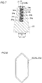
FIG. 7] FIG. 7 is a sectional view taken along line 300-300 inFIG. 4 . - [
FIG. 8] FIG. 8 is a diagram showing a concentric coil that has not been placed in slots. - [
FIG. 9] FIG. 9 is a diagram illustrating the step of placing concentric coils into slots. - [
FIG. 10] FIG. 10 is a diagram illustrating the step of dropping varnish onto concentric coils. - [
FIG. 11] FIG. 11 is a diagram showing how varnish is dropped onto a concentric coil. - [
FIG. 12] FIG. 12 is a diagram showing a single concentric coil placed in slots of a rotating electrical machine according to a second embodiment of the present invention. - Embodiments of the present invention will be described based on the accompanying drawings.
- The structure of a rotating
electrical machine 100 according to a first embodiment will be described with reference toFIGS. 1 to 7 .FIGS. 2 to 5 and11 and FIG. 12 showing a second embodiment are schematic views of anannular stator core 20 laid out flat, showing the radially inner side of thestator core 20 as viewed from the central axis of rotation of arotor core 10. - As shown in
FIG. 1 , the rotatingelectrical machine 100 includes therotor core 10. Therotor core 10 is provided with a plurality ofpermanent magnets 11. The plurality ofpermanent magnets 11 are arranged at substantially regular angular intervals in the circumferential direction. - The rotating
electrical machine 100 further includes thestator core 20 disposed so as to face therotor core 10 in the radial direction. Thestator core 20 includes a plurality ofteeth 21 and a plurality ofslots 22 each located between adjacent ones of theteeth 21.Concentric coils 30 each formed by concentrically winding a rectangular wire are placed in theslots 22 of thestator core 20. - The structure of the
concentric coil 30 will be described with reference toFIGS. 2 and3 .FIG. 2 shows a singleconcentric coil 30 placed in theslots 22 of thestator core 20. Theconcentric coil 30 has a substantially symmetrical shape with respect to an axis C1 passing through the center of theconcentric coil 30 in the Z direction, so that the X1 direction side and the X2 direction side of theconcentric coil 30 are mirror images of each other. The structure of the X1 direction side of theconcentric coil 30 will be described below. - The
concentric coil 30 is a coil formed by concentrically winding a rectangular wire and is placed in theslots 22 of thestator core 20. In the first embodiment, as shown inFIGS. 2 and3 , an interval L1 in the circumferential direction of thestator core 20 between an outerperipheral surface 32 of anaxial end 31 of a slot accommodatedportion 36 of theconcentric coil 30 about the winding center C of theconcentric coil 30 and thetooth 21 facing the outerperipheral surface 32 is larger than an interval L2 in the circumferential direction of thestator core 20 between an innerperipheral surface 33 of theaxial end 31 of the slot accommodatedportion 36 of theconcentric coil 30 about the winding center C of theconcentric coil 30 and thetooth 21 facing the innerperipheral surface 33. The winding center C is the middle in the circumferential direction (X direction) between a pair of slot accommodatedportions 36 of theconcentric coil 30 and the middle in the axial direction (Z direction) between a pair ofcoil end portions 35 of theconcentric coil 30 excluding lead portions, not shown. The lead portions are one end and the other end of the rectangular wire forming theconcentric coil 30. The lead portions function as a power line for connection to an external circuit such as a power supply, a neutral line for connection to a connection point (neutral point) to aconcentric coil 30 of another phase, etc. - Specifically, in the first embodiment,
insulating paper 23 is placed between theconcentric coil 30 and theslot 22. The innerperipheral surface 33 of theaxial end 31 contacts the insulatingpaper 23. Theaxial end 31 and the tooth 21 (axial end 21a) located on the side (X2 direction side) facing the innerperipheral surface 33 of theaxial end 31 are separated by the interval L2 in the circumferential direction which corresponds to the thickness t of theinsulating paper 23. Theinsulating paper 23 is one example of the "insulating member." - In the first embodiment, as shown in
FIG. 2 , the interval L1 in the circumferential direction between each of the axial ends 31 (axial ends 311, 312) of theconcentric coil 30 which are located at both ends on one side (Z1 direction side) and the other side (Z2 direction side) in the axial direction (Z direction) of theslot 22 and the tooth 21 (eachaxial end 21a) located on the side (X1 direction side) facing the outerperipheral surface 32 of theaxial end 31 is larger than the interval L2 in the circumferential direction between each of the axial ends 31 (axial ends 311, 312) and the tooth 21 (eachaxial end 21a) located on the side (X2 direction side) facing the innerperipheral surface 33 of theaxial end 31. - In the first embodiment, as shown in
FIG. 3 , the interval L1 in the circumferential direction between theconcentric coil 30 and the tooth 21 (corresponding portion 21b) on the side (X1 direction side) facing the outerperipheral surface 32 of theconcentric coil 30 gradually decreases from anaxial end 22a of theslot 22 toward anaxial middle portion 22b of theslot 22. Specifically, the interval L1 in the circumferential direction between theconcentric coil 30 and the tooth 21 (correspondingportion 21b) facing the outerperipheral surface 32 of theconcentric coil 30 gradually decreases from theaxial end 22a of theslot 22 and toward the vicinity of the axialmiddle portion 22b of theslot 22 so that the interval L1 in the circumferential direction between theconcentric coil 30 and the tooth 21 (correspondingportion 21b) becomes the smallest in the vicinity of the axialmiddle portion 22b of theslot 22. The outerperipheral surface 32 of theconcentric coil 30 and the insulatingpaper 23 are in contact with each other in the vicinity of the axialmiddle portion 22b of theslot 22. - As shown in
FIG. 2 , theconcentric coil 30 has a substantially symmetrical shape with respect to an axis C2 passing through the center of theconcentric coil 30 in the X direction, so that the Z1 direction side and the Z2 direction side of theconcentric coil 30 are mirror images of each other. That is, in both of theaxial end 311 and theaxial end 312, the interval L1 in the circumferential direction between theconcentric coil 30 and the tooth 21 (correspondingportion 21b) on the side (X1 direction side) facing the outerperipheral surface 32 of theconcentric coil 30 gradually decreases from theaxial end 22a of theslot 22 toward the axialmiddle portion 22b (the vicinity of the axialmiddle portion 22b) of theslot 22. - Namely, the
concentric coil 30 is placed in theslot 22 such that the axial ends 31 (311, 312) of theconcentric coil 30 which are located at the axial ends 22a of theslot 22 are located closer to the axis C1 of theconcentric coil 30. Theconcentric coil 30 is placed in theslot 22 such that acoil portion 313 of theconcentric coil 30 which is located in the vicinity of the axialmiddle portion 22b of theslot 22 is located farther away from the axis C1 of theconcentric coil 30. - The structure of two
concentric coils 30 placed in asingle slot 22 will be described with reference toFIG. 4 . Although two concentric coils 30 (30a, 30b) placed in asingle slot 22 are shown inFIG. 4 , two concentric coils 30 (30a, 30b) are actually placed in everyslot 22. - As shown in
FIG. 5 , theconcentric coils 30 include a firstconcentric coil 30a and a secondconcentric coil 30b which are placed in thesame slot 22 located between afirst tooth 211 and asecond tooth 212 which are adjacent to each other. An outerperipheral surface 32a of a firstaxial end 31a of a slot accommodatedportion 36 of the firstconcentric coil 30a about the winding center C of theconcentric coil 30 faces thefirst tooth 211, and an outerperipheral surface 32b of a secondaxial end 31b of a slot accommodatedportion 36 of the secondconcentric coil 30b about the winding center C of theconcentric coil 30 faces thesecond tooth 212. - In the first embodiment, an interval L11 in the circumferential direction between the first
axial end 31a of the firstconcentric coil 30a and anaxial end 211a of thefirst tooth 211 facing the outerperipheral surface 32a of the firstaxial end 31a of the firstconcentric coil 30a is larger than an interval L21 in the circumferential direction between the firstaxial end 31 a of the firstconcentric coil 30a and anaxial end 212a of thesecond tooth 212 facing an innerperipheral surface 33a of the firstaxial end 31a. The interval L11 is equal to the interval L1, and the interval L21 is equal to the interval L2. - An interval L12 in the circumferential direction between the
axial end 31b of the secondconcentric coil 30b and theaxial end 212a of thesecond tooth 212 facing the outerperipheral surface 32b of the secondaxial end 31b of the secondconcentric coil 30b is larger than an interval L22 in the circumferential direction between the secondaxial end 31b of the secondconcentric coil 30b and theaxial end 211a of thefirst tooth 211 facing an innerperipheral surface 33b of the secondaxial end 31b. The interval L12 is equal to the interval L1, and the interval L22 is equal to the interval L2. - As shown in
FIGS. 6 and7 , the firstconcentric coil 30a and the secondconcentric coil 30b are formed by concentrically winding arectangular wire 34a and arectangular wire 34b into a plurality of turns. In the first embodiment, in thesame slot 22 where the firstconcentric coil 30a and the secondconcentric coil 30b are placed, the turns of therectangular wire 34a of the firstconcentric coil 30a and the turns of therectangular wire 34b of the secondconcentric coil 30b are alternately arranged at intervals L3 in the radial direction. - Specifically, as shown in
FIG. 6 , on theaxial end 22a side of theslot 22, the turns of therectangular wire 34a of the firstconcentric coil 30a are placed on the X2 direction side of theslot 22, and the turns of therectangular wire 34b of the secondconcentric coil 30b are placed on the X1 direction side of theslot 22. As shown inFIG. 7 , in the vicinity of the axialmiddle portion 22b of theslot 22, the turns of therectangular wire 34a of the firstconcentric coil 30a are placed on the X1 direction side of theslot 22, and the turns of therectangular wire 34b of the secondconcentric coil 30b are placed on the X2 direction side of theslot 22. That is, the turns of therectangular wire 34a of the firstconcentric coil 30a and the turns of therectangular wire 34b of the secondconcentric coil 30b are arranged so as to cross each other in theslot 22 as viewed from the radially inner side of thestator core 20. -
Varnish 40 filling theslots 22 will be described with reference toFIG. 3 and5 to 7 . Thevarnish 40 filling theslots 22 is not shown inFIGS. 1, 2 , and4 . Thevarnish 40 is one example of the "fixing agent." - As shown in
FIGS. 3 and5 to 7 , thevarnish 40 fills between eachconcentric coil 30 and the insulating paper 34 placed in theslot 22. That is, in the first embodiment, as shown inFIG. 3 , thevarnish 40 fills between theaxial end 31 of the slot accommodatedportion 36 and thetooth 21 facing the outerperipheral surface 32 of theaxial end 31 and between theaxial end 31 of the slot accommodatedportion 36 and thetooth 21 facing the innerperipheral surface 33 of theaxial end 31. As shown inFIGS. 6 and7 , thevarnish 40 fills between each turn of therectangular wire 34a of the firstconcentric coil 30a and each turn of therectangular wire 34b of the secondconcentric coil 30b which face each other in the radial direction. - The first embodiment has the following effects.
- In the case of a coil made of a rectangular wire, a possible method to impregnate the space between the coil made of a rectangular wire and each coil mounting portion (slot) of a stator with varnish is to drop varnish from above into the coil made of a rectangular wire by using gravity rather than by using capillary action so that the varnish flows down. In the method in which varnish is dropped from above into a coil made of a rectangular wire by using gravity so that the varnish flows down, the amount of varnish (fixing agent) filling a slot varies depending on the positional relationship between an axial end of a slot accommodated portion and the slot. Accordingly, the coil is not sufficiently fixed if the amount of varnish is small. In the first embodiment, as shown in
FIG. 3 , the interval L1 in the circumferential direction of thestator core 20 between the outerperipheral surface 32 of theaxial end 31 of the slot accommodatedportion 36 of theconcentric coil 30 about the winding center of theconcentric coil 30 and thetooth 21 facing the outerperipheral surface 32 is larger than the interval L2 in the circumferential direction of thestator core 20 between the innerperipheral surface 33 of theaxial end 31 of the slot accommodatedportion 36 of theconcentric coil 30 about the winding center of theconcentric coil 30 and thetooth 21 facing the innerperipheral surface 33. Accordingly, in the case where thevarnish 40 is dropped onto the outerperipheral surface 32 of theconcentric coil 30, thevarnish 40 can be easily guided into theslot 22 when flowing along the outerperipheral surface 32 of theconcentric coil 30, because the interval L1 (clearance) in the circumferential direction between the outerperipheral surface 32 of theaxial end 31 and thetooth 21 is large at theaxial end 21 a of the tooth 21 (theaxial end 22a of the slot 22). As a result, even in the case of using theconcentric coil 30 made of a rectangular wire, theslots 22 can be sufficiently filled with thevarnish 40 and theconcentric coil 30 can be fixed firmly. - In the first embodiment, as shown in
FIG. 3 , the interval L1 in the circumferential direction between theconcentric coil 30 and the tooth 21 (correspondingportion 21b) facing the outerperipheral surface 32 of theconcentric coil 30 gradually decreases from theaxial end 22a of theslot 22 toward the axialmiddle portion 22b of theslot 22. Accordingly, in the vicinity of theaxial end 22a of theslot 22, thevarnish 40 is guided into theslot 22 mainly by gravity, whereas on the axialmiddle portion 22b side of theslot 22, thevarnish 40 is guided into theslot 22 by capillary action in addition to gravity. Theslot 22 is thus smoothly filled with thevarnish 40. - In the first embodiment, as shown in
FIG. 3 , the interval L1 in the circumferential direction between theconcentric coil 30 and the tooth 21 (correspondingportion 21b) facing the outerperipheral surface 32 of theconcentric coil 30 gradually decreases from theaxial end 22a of theslot 22 toward the vicinity of the axialmiddle portion 22b of theslot 22 so that the interval L1 in the circumferential direction between theconcentric coil 30 and the tooth 21 (correspondingportion 21b) is the smallest in the vicinity of the axialmiddle portion 22b of theslot 22. However, thevarnish 40 flows along theaxial end 31 and flows to the back surface of theaxial end 31, so that thevarnish 40 can smoothly fill (be guided) down to the vicinity of the axialmiddle portion 22b of theslot 22. - In the first embodiment, as shown in
FIG. 2 , the interval L1 in the circumferential direction between each of the axial ends 31 (311, 312) of theconcentric coil 30 which are located at both ends on one side and the other side in the axial direction of theslot 22 and the tooth 21 (eachaxial end 21 a) facing the outerperipheral surface 32 of theaxial end 31 is larger than the interval L2 in the circumferential direction between each of the axial ends 31 and the tooth 21 (eachaxial end 21a) facing the innerperipheral surface 33 of theaxial end 31. Thevarnish 40 can thus be easily guided into theslot 22 on both the one side and the other side in the axial direction of theslot 22, whereby theslot 22 can thus be more effectively filled with thevarnish 40. - In the first embodiment, as shown in
FIG. 5 , the interval L11 in the circumferential direction between the firstaxial end 31a of the firstconcentric coil 30a and the first tooth 211 (axial end 211a) facing the outerperipheral surface 32a of the firstaxial end 31a of the firstconcentric coil 30a is larger than the interval L21 in the circumferential direction between the firstaxial end 31a of the firstconcentric coil 30a and the second tooth 212 (axial end 212a) facing the innerperipheral surface 33a of the firstaxial end 31 a. The interval L12 in the circumferential direction between the secondaxial end 31b of the secondconcentric coil 30b and the second tooth 212 (axial end 212a) facing the outerperipheral surface 32b of the secondaxial end 31b of the secondconcentric coil 30b is larger than the interval L22 in the circumferential direction between the secondaxial end 31b of the secondconcentric coil 30b and the first tooth 211 (axial end 211a) facing the innerperipheral surface 33b of the secondaxial end 31b. Accordingly, even when the firstconcentric coil 30a and the secondconcentric coil 30b are placed in asingle slot 22, thevarnish 40 can be easily guided into theslot 22. - In the first embodiment, as shown in
FIGS. 6 and7 , in thesame slot 22 where the firstconcentric coil 30a and the secondconcentric coil 30b are placed, the turns of therectangular wire 34a of the firstconcentric coil 30a and the turns of therectangular wire 34b of the secondconcentric coil 30b are alternately arranged at the intervals L3 in the radial direction. Thevarnish 40 thus fills between each turn of therectangular wire 34a of the firstconcentric coil 30a and each turn of therectangular wire 34b of the secondconcentric coil 30b, whereby the firstconcentric coil 30a and the secondconcentric coil 30b can be fixed firmly. - In the first embodiment, as shown in
FIG. 3 , the insulatingpaper 23 is disposed between theslot 22 and theconcentric coil 30. The innerperipheral surface 33 of theaxial end 31 is in contact with the insulatingpaper 23, so that theaxial end 31 and the tooth 21 (axial end 21a) facing the innerperipheral surface 33 of theaxial end 31 are separated by the interval L2 in the circumferential direction which corresponds to the thickness t of the insulatingpaper 23. Accordingly, unlike the case where theaxial end 31 and the tooth 21 (axial end 21a) facing the innerperipheral surface 33 of theaxial end 31 are separated by an interval larger than the thickness t of the insulatingpaper 23, the interval L1 in the circumferential direction between theaxial end 31 located at theaxial end 22a of theslot 22 and the tooth 21 (axial end 21 a) facing the outerperipheral surface 32 of theaxial end 31 can be increased. As a result, thevarnish 40 can be more easily guided into theslot 22. - In the first embodiment, as shown in
FIG. 3 , thevarnish 40 fills between theaxial end 31 of the slot accommodatedportion 36 and thetooth 21 facing the outerperipheral surface 32 of theaxial end 31 and between theaxial end 31 of the slot accommodatedportion 36 and thetooth 21 facing the innerperipheral surface 33 of theaxial end 31. Since thevarnish 40 thus fills both the outerperipheral surface 32 side and the innerperipheral surface 33 side of theaxial end 31, theconcentric coil 30 can be fixed more firmly. Since thevarnish 40 solidifies relatively quickly, theconcentric coil 30 can be fixed relatively quickly. - A method for manufacturing the rotating
electrical machine 100 will be described with reference toFIGS. 1 and8 to 11 .FIGS. 9 and 10 show two concentric coils 30 (the firstconcentric coil 30a and the secondconcentric coil 30b) being placed in theslots 22 of thestator core 20. - As shown in
FIG. 8 , the concentric coils 30 (the firstconcentric coil 30a and the secondconcentric coil 30b) each formed by concentrically winding a rectangular wire are prepared. - As shown in
FIG. 9 , the firstconcentric coil 30a and the secondconcentric coil 30b are then attached to ajig 50 such that the turns of therectangular wire 34a of the firstconcentric coil 30a and the turns of therectangular wire 34b of the secondconcentric coil 30b are alternately arranged in the radial direction. - As shown in
FIG. 10 , in the first embodiment, theconcentric coils 30 are placed in theslots 22 such that the interval L1 in the circumferential direction of thestator core 20 between the outerperipheral surface 32 of eachaxial end 31 of the slot accommodatedportion 36 of theconcentric coil 30 about the winding center of theconcentric coil 30 and thetooth 21 facing the outerperipheral surface 32 in the circumferential direction of thestator core 20 is larger than the interval L2 in the circumferential direction of thestator core 20 between eachaxial end 31 and thetooth 21 facing the innerperipheral surface 33 of theaxial end 31 of the slot accommodatedportion 36 of theconcentric coil 30 about the winding center of theconcentric coil 30. Specifically, the concentric coils 30 (the firstconcentric coil 30a and the secondconcentric coil 30b) attached to thejig 50 are pressed outward in the radial direction so as to be inserted into theslot 22. Eachconcentric coil 30 is thus gradually widened in the circumferential direction and changes from the shape shown inFIG. 8 into the shape (barrel shape) shown inFIG. 11 , namely such a shape that the inside width in the circumferential direction is large and those portions of theconcentric coil 30 which are located in theslots 22 are curved along the axial direction. - As shown in
FIG. 10 , in the first embodiment, with thestator core 20 being placed so that itsaxial end face 20a faces upward (in the Z1 direction), thevarnish 40 is supplied from above to flow (dropped to flow down) along the outerperipheral surfaces 32 of theconcentric coils 30, whereby theslots 22 are filled with thevarnish 40. Specifically, with thestator core 20 being rotated in the circumferential direction (R direction), thevarnish 40 is dropped onto the coil ends 35 from avarnish dropping device 41. As shown inFIG. 11 , thevarnish 40 thus flows along the outerperipheral surfaces 32 of the concentric coils 30 (coil ends 35) into theslots 22. In the vicinity of theaxial end 22a of eachslot 22, thevarnish 40 is guided into theslot 22 mainly by gravity, whereas on the axialmiddle portion 22b side of eachslot 22, thevarnish 40 is guided into theslot 22 by capillary action in addition to gravity. - The
varnish 40 is dropped on each side of thestator core 20, namely on one side (Z1 direction side) and the other side (Z2 direction side) of thestator core 20. Thestator core 20 may be rotated 360 degrees, or if thevarnish 40 is not sufficiently dropped onto a plurality of concentric coils 30 (into the slots 22) with the one full rotation of thestator core 20, thestator core 20 may be rotated 360 degrees a plurality of times with the radial position from which thevarnish 40 is dropped being shifted after each full rotation of thestator core 20. - The
varnish 40 thus fixes theconcentric coils 30 and the insulating paper 34 together and fixes the turns of the rectangular wires of theconcentric coils 30. This improves heat transfer properties between theconcentric coil 30 and thestator core 20. - The first embodiment has the following effects.
- In the first embodiment, the rotating
electrical machine 100 is manufactured as described above, so that thevarnish 40 can be easily guided into theslots 22 as shown inFIG. 11 . As a result, even in the case of using theconcentric coils 30 made of a rectangular wire, the rotatingelectrical machine 100 having theslots 22 sufficiently filled with thevarnish 40 and having the firmly fixedconcentric coils 30 can be manufactured. - In the first embodiment, as shown in
FIG. 10 , thevarnish 40 is dropped onto the coil ends 35 of theconcentric coils 30 with thestator core 20 being rotated. Thevarnish 40 can thus be easily dropped onto the plurality ofconcentric coils 30 placed in the plurality ofslots 22. - The structure of a rotating
electrical machine 110 according to a second embodiment will be described with reference toFIG. 12 . - As in the first embodiment, in a
concentric coil 130 of the rotatingelectrical machine 110, an interval L4 in the circumferential direction between anaxial end 131 of aconcentric coil 130 which is located at anaxial end 22a of aslot 22 and one of adjacent teeth 21 (axial end 21a) which faces an outerperipheral surface 132 of theaxial end 131 is larger than an interval L5 in the circumferential direction between theaxial end 131 and the tooth 121 (axial end 21a) facing an innerperipheral surface 133 of theaxial end 131. - In the second embodiment, the interval L4 in the circumferential direction between the
concentric coil 130 and the tooth 21 (correspondingportion 21b) facing the outerperipheral surface 132 of theconcentric coil 130 gradually decreases from theaxial end 22a on the Z1 direction side of theslot 22 toward an axialmiddle portion 22b of theslot 22, and then gradually increases toward the vicinity of the axialmiddle portion 22b of theslot 22. The interval L4 then gradually decreases, and thereafter gradually increases toward theaxial end 22a on the Z2 direction side. The portion of theconcentric coil 130 which is placed in theslot 22 thus has a winding shape (wave shape). In other words, the portion of theconcentric coil 130 which is placed in theslot 22 has a W-shape. - Other configurations of the second embodiment and a method for manufacturing the rotating
electrical machine 110 of the second embodiment are similar to the first embodiment. - The second embodiment has the following effects.
- In the second embodiment, as shown in
FIG. 12 , the interval L4 in the circumferential direction between theconcentric coil 130 and the tooth 21 (correspondingportion 21b) facing the outerperipheral surface 132 of theconcentric coil 130 gradually decreases from theaxial end 22a of theslot 22 toward the axialmiddle portion 22b of theslot 22, and then gradually increases toward the vicinity of the axialmiddle portion 22b of theslot 22. Accordingly, in the case where two concentric coils 30 (the firstconcentric coil 30a and the secondconcentric coil 30b) are placed in a single slot 22 (seeFIGS. 6 and7 ), the number of times the firstconcentric coil 30a and the secondconcentric coil 30b intersect as viewed from the radially inner side of thestator core 20 is larger (four times) than in the first embodiment (twice). As a result, the area where the interval between the firstconcentric coil 30a and the secondconcentric coil 30b is small is increased, which makes it easy to more smoothly guidevarnish 40 into theslots 22 by capillary action. - Other effects of the second embodiment are similar to those of the first embodiment.
- The embodiments disclosed herein are merely by way of example in all respects and should not be construed as restrictive. The scope of the present invention is defined by the claims rather than by the above description of the embodiments, and the invention is intended to cover all alterations (modifications) that are made within the spirit and scope of the claims.
- For example, the first and second embodiments are described with respect to an example in which the inner peripheral surface of the axial end is in contact with the insulating paper and the axial end and the axial end of the tooth facing the inner peripheral surface of the axial end are separated by the interval corresponding to the thickness of the insulating paper. However, the present invention is not limited to this. For example, the inner peripheral surface of the axial end may not be in contact with the insulating paper.
- The first and second embodiments are described with respect to an example in which the interval in the circumferential direction between the concentric coil and the tooth facing the outer peripheral surface of the concentric coil gradually decreases from the axial end of the slot toward the axial middle portion of the slot. However, the present invention is not limited to this. For example, the concentric coil may be formed so that the interval in the circumferential direction between the concentric coil and the tooth facing the outer peripheral surface of the concentric coil does not change from the axial end of the slot toward the axial middle portion of the slot. That is, the portion of the concentric coil which is placed in the slot may have a linear shape along the tooth (in the Z direction).
- The first and second embodiments are described with respect to an example in which the interval in the circumferential direction between each of the axial ends of the concentric coil which are located at both ends on one side and the other side in the axial direction of the slot and the tooth facing the outer peripheral surface of the axial end is larger than the interval in the circumferential direction between each of the axial ends and the tooth facing the inner peripheral surface of the axial end. However, the present invention is not limited to this. For example, the concentric coil may be formed so that the interval in the circumferential direction between the axial end of the concentric coil which is located at one of the ends on one side and the other side in the axial direction of the slot and the tooth facing the outer peripheral surface of the axial end is larger than the interval in the circumferential direction between the axial end and the tooth facing the inner peripheral surface of the axial end.
- The first and second embodiments are described with respect to an example in which two concentric coils are placed in the same slot. However, the present invention is not limited to this. For example, a single concentric coil or three or more concentric coils may be placed in the same slot.
- The first and second embodiments are described with respect to an example in which insulating paper is placed between each slot and the concentric coil. However, the present invention is not limited to this. In the present invention, an insulating member other than insulating paper may be placed between each slot and the concentric coil.
- The first and second embodiments are described with respect to an example in which the teeth are filled with varnish. However, the present invention is not limited to this. In the present invention, the teeth may be filled with a fixing agent other than varnish (e.g., an adhesive).
- The first and second embodiments are described with respect to an example in which varnish is dropped onto the coil ends of the concentric coils with the stator core being rotated. However, the present invention is not limited to this. For example, varnish may be dropped onto the coil ends of the concentric coils with the stator core being held stationary.
-
- 10 Rotor Core
- 11 Permanent Magnet
- 20 Stator Core
- 20a Axial End Face (of Stator Core)
- 21 Tooth
- 21a Axial End (of Tooth)
- 21b Corresponding Portion (of Tooth)
- 22 Slot
- 22a Axial End (of Slot)
- 22b Axial Middle Portion (of Slot)
- 23 Insulating Paper (Insulating Member)
- 30, 130 Concentric Coil
- 30a First Concentric Coil
- 30b Second Concentric Coil
- 31,131,311,312 Axial End
- 31 a First Axial End
- 31b Second Axial End
- 32, 32a, 32b, 132 Outer Peripheral Surface
- 33, 33a, 33b, 133 Inner Peripheral Surface
- 34a Rectangular Wire (of First Concentric Coil)
- 34b Rectangular Wire (of Second Concentric Coil)
- 35 Coil End
- 36 Slot Accommodated Portion
- 40 Varnish (Fixing Agent)
- 100,110 Rotating Electrical Machine
- 211 First Tooth
- 212 Second Tooth
- C Winding Center
- L1, L2, L3, L4, L5, L11, L12, L21, L22 Interval
- t Thickness
Claims (12)
- A stator core, comprising:a stator core including a plurality of teeth and a plurality of slots each located between adjacent ones of the teeth; anda concentric coil formed by concentrically winding a rectangular wire and placed in the slots of the stator core, whereinan interval in a circumferential direction of the stator core between an outer peripheral surface of an axial end of a slot accommodated portion of the concentric coil about a winding center of the concentric coil and the tooth facing the outer peripheral surface is larger than an interval in the circumferential direction of the stator core between an inner peripheral surface of the axial end of the slot accommodated portion of the concentric coil about the winding center of the concentric coil and the tooth facing the inner peripheral surface.
- The stator core according to claim 1, wherein
an interval in the circumferential direction between the concentric coil and the tooth facing an outer peripheral surface of the concentric coil decreases from an axial end of the slot toward an axial middle portion of the slot. - The stator core according to claim 2, wherein
the interval in the circumferential direction between the concentric coil and the tooth facing the outer peripheral surface of the concentric coil decreases from the axial end of the slot toward a vicinity of the axial middle portion of the slot so that the interval in the circumferential direction between the concentric coil and the tooth is the smallest in the vicinity of the axial middle portion of the slot. - The stator core according to claim 2, wherein
the interval in the circumferential direction between the concentric coil and the tooth facing the outer peripheral surface of the concentric coil gradually decreases from the axial end of the slot toward the axial middle portion of the slot, and then increases toward a vicinity of the axial middle portion of the slot. - The stator core according to any one of claims 1 to 4, wherein
the interval in the circumferential direction between each of the axial ends of the concentric coil which are located at both ends on one side and the other side in an axial direction of the slot and the tooth facing the outer peripheral surface of the axial end is larger than the interval in the circumferential direction between each of the axial ends and the tooth facing the inner peripheral surface of the axial end. - The stator core according to any one of claims 1 to 5, wherein
the teeth includes a first tooth and a second tooth which are located adjacent to each other,
the concentric coil includes a first concentric coil and a second concentric coil which are placed in the same slot located between the first and second teeth located adjacent to each other, and the outer peripheral surface of the axial end of the slot accommodated portion of the first concentric coil about the winding center of the concentric coil faces the first tooth and the outer peripheral surface of the axial end of the slot accommodated portion of the second concentric coil about the winding center of the concentric coil faces the second tooth,
an interval in the circumferential direction between a first axial end of the first concentric coil and the first tooth facing an outer peripheral surface of the first axial end of the first concentric coil is larger than an interval in the circumferential direction between the first axial end of the first concentric coil and the second tooth facing an inner peripheral surface of the first axial end, and
an interval in the circumferential direction between a second axial end of the second concentric coil and the second tooth facing an outer peripheral surface of the second axial end of the second concentric coil is larger than an interval in the circumferential direction between the second axial end of the second concentric coil and the first tooth facing an inner peripheral surface of the second axial end. - The stator core according to claim 6, wherein
in the same slot where the first concentric coil and the second concentric coil are placed, turns of a rectangular wire of the first concentric coil and turns of a rectangular wire of the second concentric coil are alternately arranged at intervals in a radial direction. - The stator core according to any one of claims 1 to 7, further comprising:an insulating member placed between the slot and the concentric coil, whereinthe inner peripheral surface of the axial end is in contact with the insulating member, andthe axial end and the tooth facing the inner peripheral surface of the axial end are separated by an interval in the circumferential direction which corresponds to a thickness of the insulating member.
- The stator core according to any one of claims 1 to 8, further comprising:a fixing agent that fills between the axial end of the slot accommodated portion and the tooth facing the outer peripheral surface of the axial end and between the axial end of the slot accommodated portion and the tooth facing the inner peripheral surface of the axial end.
- The stator core according to claim 9, wherein
the fixing agent includes varnish. - A method for manufacturing a stator core including a stator core including a plurality of teeth and a plurality of slots each located between adjacent ones of the teeth, and a concentric coil formed by concentrically winding a rectangular wire and placed in the slots of the stator core, comprising the steps of:placing the concentric coil in the slots so that an interval in a circumferential direction of the stator core between an outer peripheral surface of an axial end of a slot accommodated portion of the concentric coil about a winding center of the concentric coil and the tooth facing the outer peripheral surface is larger than an interval in the circumferential direction of the stator core between an inner peripheral surface of the axial end of the slot accommodated portion of the concentric coil about the winding center of the concentric coil and the tooth facing the inner peripheral surface; andwith the stator core being placed so that its axial end face faces upward, supplying a fixing agent so that the fixing agent flows along the outer peripheral surface of the concentric coil, thereby filling the slots with the fixing agent.
- The method for manufacturing a stator core according to claim 11, wherein
the concentric coil includes a coil end projecting from the stator core, and
the step of filling the slots with the fixing agent includes the step of supplying the fixing agent to the coil end of the concentric coil while rotating the stator core.
Applications Claiming Priority (2)
| Application Number | Priority Date | Filing Date | Title |
|---|---|---|---|
| JP2015084275 | 2015-04-16 | ||
| PCT/JP2016/062135 WO2016167356A1 (en) | 2015-04-16 | 2016-04-15 | Stator core and stator core production method |
Publications (3)
| Publication Number | Publication Date |
|---|---|
| EP3261227A1 true EP3261227A1 (en) | 2017-12-27 |
| EP3261227A4 EP3261227A4 (en) | 2018-04-04 |
| EP3261227B1 EP3261227B1 (en) | 2019-09-25 |
Family
ID=57125935
Family Applications (1)
| Application Number | Title | Priority Date | Filing Date |
|---|---|---|---|
| EP16780147.1A Active EP3261227B1 (en) | 2015-04-16 | 2016-04-15 | Stator core and stator core production method |
Country Status (5)
| Country | Link |
|---|---|
| US (1) | US10763718B2 (en) |
| EP (1) | EP3261227B1 (en) |
| JP (1) | JP6436231B2 (en) |
| CN (1) | CN107431403B (en) |
| WO (1) | WO2016167356A1 (en) |
Families Citing this family (2)
| Publication number | Priority date | Publication date | Assignee | Title |
|---|---|---|---|---|
| JP2018050389A (en) * | 2016-09-21 | 2018-03-29 | 本田技研工業株式会社 | Stator and manufacturing method thereof |
| CN120675367B (en) * | 2025-08-20 | 2025-11-14 | 湖南星创智能装备有限公司 | Stator and insulator assembly device and equipment |
Family Cites Families (18)
| Publication number | Priority date | Publication date | Assignee | Title |
|---|---|---|---|---|
| US3618337A (en) | 1970-06-22 | 1971-11-09 | Carrier Corp | Hermetic refrigeration compressor |
| JP2905365B2 (en) * | 1993-07-15 | 1999-06-14 | 株式会社日立製作所 | Method for manufacturing armature of rotating electric machine |
| JP2003143791A (en) * | 2001-11-02 | 2003-05-16 | Toyota Motor Corp | Rotating electric machine stator |
| JP4811047B2 (en) * | 2006-02-17 | 2011-11-09 | 日産自動車株式会社 | Concentrated winding motor |
| JP2009189078A (en) | 2008-02-01 | 2009-08-20 | Toyota Industries Corp | Rotating electric machine stator and rotating electric machine |
| DE102008020426A1 (en) | 2008-04-24 | 2009-10-29 | Bayerische Motoren Werke Aktiengesellschaft | Electric machine with cooling channels in the rotor |
| DE102009032883A1 (en) | 2009-07-13 | 2011-01-27 | Siemens Aktiengesellschaft | Winding arrangement |
| JP2011120356A (en) * | 2009-12-02 | 2011-06-16 | Toyota Motor Corp | Stator and method of manufacturing stator |
| US20110260572A1 (en) * | 2010-04-27 | 2011-10-27 | Honda Motor Co., Ltd. | Motor stator and manufacturing method of motor stator |
| JP5290244B2 (en) | 2010-06-18 | 2013-09-18 | 株式会社小松製作所 | Electric motor for construction machine and cooling circuit for electric motor |
| JP5393605B2 (en) * | 2010-07-12 | 2014-01-22 | 三菱電機株式会社 | Electric motor stator |
| JP5585656B2 (en) | 2010-08-27 | 2014-09-10 | トヨタ自動車株式会社 | Vehicle control device |
| JP2012090511A (en) * | 2010-10-22 | 2012-05-10 | Toyota Motor Corp | Component of rotary electric machine |
| JP2013132151A (en) | 2011-12-22 | 2013-07-04 | Toyota Motor Corp | Rotary electric machine and rotary electric machine cooling system |
| JP5762638B2 (en) | 2012-08-03 | 2015-08-12 | 三菱電機株式会社 | Rotating electric machine |
| JP5920259B2 (en) | 2013-03-19 | 2016-05-18 | 株式会社安川電機 | Coil, rotating electric machine, and method of manufacturing rotating electric machine |
| JP5720715B2 (en) | 2013-03-29 | 2015-05-20 | 株式会社デンソー | Rotating electric machine |
| JP6132721B2 (en) * | 2013-09-20 | 2017-05-24 | 本田技研工業株式会社 | Stator manufacturing method and varnish dripping device |
-
2016
- 2016-04-15 JP JP2017512601A patent/JP6436231B2/en active Active
- 2016-04-15 CN CN201680020081.9A patent/CN107431403B/en active Active
- 2016-04-15 EP EP16780147.1A patent/EP3261227B1/en active Active
- 2016-04-15 US US15/561,176 patent/US10763718B2/en active Active
- 2016-04-15 WO PCT/JP2016/062135 patent/WO2016167356A1/en not_active Ceased
Also Published As
| Publication number | Publication date |
|---|---|
| US20180159398A1 (en) | 2018-06-07 |
| CN107431403A (en) | 2017-12-01 |
| JPWO2016167356A1 (en) | 2017-12-14 |
| EP3261227A4 (en) | 2018-04-04 |
| US10763718B2 (en) | 2020-09-01 |
| JP6436231B2 (en) | 2018-12-12 |
| CN107431403B (en) | 2019-10-15 |
| WO2016167356A1 (en) | 2016-10-20 |
| EP3261227B1 (en) | 2019-09-25 |
Similar Documents
| Publication | Publication Date | Title |
|---|---|---|
| KR101741658B1 (en) | Stator for rotary electric machine | |
| KR101605642B1 (en) | Conductive wire and electrical rotating machine | |
| KR101514122B1 (en) | Rotary electric machine | |
| JP6979464B2 (en) | Rotating machine stator | |
| JP5920259B2 (en) | Coil, rotating electric machine, and method of manufacturing rotating electric machine | |
| EP2680412B1 (en) | Arrangement of coil wires in a rotor of an electric motor | |
| US10574111B2 (en) | Rotating electric machine with lane-changed coils | |
| NZ591332A (en) | Method for manufacturing a stator for an energy converting apparatus with stator windings which increase in cross-sectional area radially outwards | |
| CN106416024A (en) | Axial Gap Type Rotating Electric Machines | |
| JPWO2017195637A1 (en) | Armature manufacturing method, rotating electrical machine manufacturing method, armature, rotating electrical machine, and armature manufacturing apparatus | |
| CN106030993B (en) | rotating electrical machine | |
| EP3261227B1 (en) | Stator core and stator core production method | |
| JP2017118640A (en) | Electric motor having wave winding coil and method for manufacturing the same | |
| JP2005318669A (en) | Stator | |
| EP3261225A1 (en) | Rotating electrical machine | |
| JP2012222944A (en) | Stator | |
| JP6351861B2 (en) | Armature manufacturing method | |
| JP2016046867A (en) | Rotating electrical machine stator | |
| JP2018129879A (en) | Resolver stator structure and resolver using the same | |
| JP2021090255A (en) | Electric motor and method for manufacturing the same | |
| JP6095462B2 (en) | Rotating electric machine armature, rotating electric machine, and method of manufacturing rotating electric machine armature | |
| JP2024122647A (en) | Stator core unit, motor and coil winding method |
Legal Events
| Date | Code | Title | Description |
|---|---|---|---|
| STAA | Information on the status of an ep patent application or granted ep patent |
Free format text: STATUS: THE INTERNATIONAL PUBLICATION HAS BEEN MADE |
|
| PUAI | Public reference made under article 153(3) epc to a published international application that has entered the european phase |
Free format text: ORIGINAL CODE: 0009012 |
|
| STAA | Information on the status of an ep patent application or granted ep patent |
Free format text: STATUS: REQUEST FOR EXAMINATION WAS MADE |
|
| 17P | Request for examination filed |
Effective date: 20170922 |
|
| AK | Designated contracting states |
Kind code of ref document: A1 Designated state(s): AL AT BE BG CH CY CZ DE DK EE ES FI FR GB GR HR HU IE IS IT LI LT LU LV MC MK MT NL NO PL PT RO RS SE SI SK SM TR |
|
| AX | Request for extension of the european patent |
Extension state: BA ME |
|
| A4 | Supplementary search report drawn up and despatched |
Effective date: 20180302 |
|
| RIC1 | Information provided on ipc code assigned before grant |
Ipc: H02K 3/48 20060101ALI20180226BHEP Ipc: H02K 15/12 20060101ALI20180226BHEP Ipc: H02K 15/00 20060101ALI20180226BHEP Ipc: H02K 15/06 20060101ALI20180226BHEP Ipc: H02K 3/12 20060101AFI20180226BHEP |
|
| STAA | Information on the status of an ep patent application or granted ep patent |
Free format text: STATUS: EXAMINATION IS IN PROGRESS |
|
| 17Q | First examination report despatched |
Effective date: 20180423 |
|
| DAV | Request for validation of the european patent (deleted) | ||
| DAX | Request for extension of the european patent (deleted) | ||
| REG | Reference to a national code |
Ref country code: DE Ref legal event code: R079 Ref document number: 602016021341 Country of ref document: DE Free format text: PREVIOUS MAIN CLASS: H02K0003340000 Ipc: H02K0003120000 |
|
| GRAP | Despatch of communication of intention to grant a patent |
Free format text: ORIGINAL CODE: EPIDOSNIGR1 |
|
| STAA | Information on the status of an ep patent application or granted ep patent |
Free format text: STATUS: GRANT OF PATENT IS INTENDED |
|
| RIC1 | Information provided on ipc code assigned before grant |
Ipc: H02K 15/00 20060101ALN20190417BHEP Ipc: H02K 3/12 20060101AFI20190417BHEP Ipc: H02K 15/06 20060101ALI20190417BHEP Ipc: H02K 3/48 20060101ALI20190417BHEP Ipc: H02K 15/12 20060101ALI20190417BHEP |
|
| INTG | Intention to grant announced |
Effective date: 20190515 |
|
| GRAS | Grant fee paid |
Free format text: ORIGINAL CODE: EPIDOSNIGR3 |
|
| GRAA | (expected) grant |
Free format text: ORIGINAL CODE: 0009210 |
|
| STAA | Information on the status of an ep patent application or granted ep patent |
Free format text: STATUS: THE PATENT HAS BEEN GRANTED |
|
| RAP1 | Party data changed (applicant data changed or rights of an application transferred) |
Owner name: AISIN AW CO., LTD. |
|
| AK | Designated contracting states |
Kind code of ref document: B1 Designated state(s): AL AT BE BG CH CY CZ DE DK EE ES FI FR GB GR HR HU IE IS IT LI LT LU LV MC MK MT NL NO PL PT RO RS SE SI SK SM TR |
|
| REG | Reference to a national code |
Ref country code: GB Ref legal event code: FG4D |
|
| REG | Reference to a national code |
Ref country code: CH Ref legal event code: EP |
|
| REG | Reference to a national code |
Ref country code: AT Ref legal event code: REF Ref document number: 1184774 Country of ref document: AT Kind code of ref document: T Effective date: 20191015 |
|
| REG | Reference to a national code |
Ref country code: IE Ref legal event code: FG4D |
|
| REG | Reference to a national code |
Ref country code: DE Ref legal event code: R096 Ref document number: 602016021341 Country of ref document: DE |
|
| REG | Reference to a national code |
Ref country code: NL Ref legal event code: MP Effective date: 20190925 |
|
| PG25 | Lapsed in a contracting state [announced via postgrant information from national office to epo] |
Ref country code: HR Free format text: LAPSE BECAUSE OF FAILURE TO SUBMIT A TRANSLATION OF THE DESCRIPTION OR TO PAY THE FEE WITHIN THE PRESCRIBED TIME-LIMIT Effective date: 20190925 Ref country code: FI Free format text: LAPSE BECAUSE OF FAILURE TO SUBMIT A TRANSLATION OF THE DESCRIPTION OR TO PAY THE FEE WITHIN THE PRESCRIBED TIME-LIMIT Effective date: 20190925 Ref country code: NO Free format text: LAPSE BECAUSE OF FAILURE TO SUBMIT A TRANSLATION OF THE DESCRIPTION OR TO PAY THE FEE WITHIN THE PRESCRIBED TIME-LIMIT Effective date: 20191225 Ref country code: SE Free format text: LAPSE BECAUSE OF FAILURE TO SUBMIT A TRANSLATION OF THE DESCRIPTION OR TO PAY THE FEE WITHIN THE PRESCRIBED TIME-LIMIT Effective date: 20190925 Ref country code: BG Free format text: LAPSE BECAUSE OF FAILURE TO SUBMIT A TRANSLATION OF THE DESCRIPTION OR TO PAY THE FEE WITHIN THE PRESCRIBED TIME-LIMIT Effective date: 20191225 Ref country code: LT Free format text: LAPSE BECAUSE OF FAILURE TO SUBMIT A TRANSLATION OF THE DESCRIPTION OR TO PAY THE FEE WITHIN THE PRESCRIBED TIME-LIMIT Effective date: 20190925 |
|
| REG | Reference to a national code |
Ref country code: LT Ref legal event code: MG4D |
|
| PG25 | Lapsed in a contracting state [announced via postgrant information from national office to epo] |
Ref country code: GR Free format text: LAPSE BECAUSE OF FAILURE TO SUBMIT A TRANSLATION OF THE DESCRIPTION OR TO PAY THE FEE WITHIN THE PRESCRIBED TIME-LIMIT Effective date: 20191226 Ref country code: RS Free format text: LAPSE BECAUSE OF FAILURE TO SUBMIT A TRANSLATION OF THE DESCRIPTION OR TO PAY THE FEE WITHIN THE PRESCRIBED TIME-LIMIT Effective date: 20190925 Ref country code: LV Free format text: LAPSE BECAUSE OF FAILURE TO SUBMIT A TRANSLATION OF THE DESCRIPTION OR TO PAY THE FEE WITHIN THE PRESCRIBED TIME-LIMIT Effective date: 20190925 |
|
| REG | Reference to a national code |
Ref country code: AT Ref legal event code: MK05 Ref document number: 1184774 Country of ref document: AT Kind code of ref document: T Effective date: 20190925 |
|
| PG25 | Lapsed in a contracting state [announced via postgrant information from national office to epo] |
Ref country code: ES Free format text: LAPSE BECAUSE OF FAILURE TO SUBMIT A TRANSLATION OF THE DESCRIPTION OR TO PAY THE FEE WITHIN THE PRESCRIBED TIME-LIMIT Effective date: 20190925 Ref country code: NL Free format text: LAPSE BECAUSE OF FAILURE TO SUBMIT A TRANSLATION OF THE DESCRIPTION OR TO PAY THE FEE WITHIN THE PRESCRIBED TIME-LIMIT Effective date: 20190925 Ref country code: AL Free format text: LAPSE BECAUSE OF FAILURE TO SUBMIT A TRANSLATION OF THE DESCRIPTION OR TO PAY THE FEE WITHIN THE PRESCRIBED TIME-LIMIT Effective date: 20190925 Ref country code: PT Free format text: LAPSE BECAUSE OF FAILURE TO SUBMIT A TRANSLATION OF THE DESCRIPTION OR TO PAY THE FEE WITHIN THE PRESCRIBED TIME-LIMIT Effective date: 20200127 Ref country code: PL Free format text: LAPSE BECAUSE OF FAILURE TO SUBMIT A TRANSLATION OF THE DESCRIPTION OR TO PAY THE FEE WITHIN THE PRESCRIBED TIME-LIMIT Effective date: 20190925 Ref country code: RO Free format text: LAPSE BECAUSE OF FAILURE TO SUBMIT A TRANSLATION OF THE DESCRIPTION OR TO PAY THE FEE WITHIN THE PRESCRIBED TIME-LIMIT Effective date: 20190925 Ref country code: EE Free format text: LAPSE BECAUSE OF FAILURE TO SUBMIT A TRANSLATION OF THE DESCRIPTION OR TO PAY THE FEE WITHIN THE PRESCRIBED TIME-LIMIT Effective date: 20190925 Ref country code: AT Free format text: LAPSE BECAUSE OF FAILURE TO SUBMIT A TRANSLATION OF THE DESCRIPTION OR TO PAY THE FEE WITHIN THE PRESCRIBED TIME-LIMIT Effective date: 20190925 Ref country code: IT Free format text: LAPSE BECAUSE OF FAILURE TO SUBMIT A TRANSLATION OF THE DESCRIPTION OR TO PAY THE FEE WITHIN THE PRESCRIBED TIME-LIMIT Effective date: 20190925 |
|
| PG25 | Lapsed in a contracting state [announced via postgrant information from national office to epo] |
Ref country code: SM Free format text: LAPSE BECAUSE OF FAILURE TO SUBMIT A TRANSLATION OF THE DESCRIPTION OR TO PAY THE FEE WITHIN THE PRESCRIBED TIME-LIMIT Effective date: 20190925 Ref country code: CZ Free format text: LAPSE BECAUSE OF FAILURE TO SUBMIT A TRANSLATION OF THE DESCRIPTION OR TO PAY THE FEE WITHIN THE PRESCRIBED TIME-LIMIT Effective date: 20190925 Ref country code: SK Free format text: LAPSE BECAUSE OF FAILURE TO SUBMIT A TRANSLATION OF THE DESCRIPTION OR TO PAY THE FEE WITHIN THE PRESCRIBED TIME-LIMIT Effective date: 20190925 Ref country code: IS Free format text: LAPSE BECAUSE OF FAILURE TO SUBMIT A TRANSLATION OF THE DESCRIPTION OR TO PAY THE FEE WITHIN THE PRESCRIBED TIME-LIMIT Effective date: 20200224 |
|
| REG | Reference to a national code |
Ref country code: DE Ref legal event code: R097 Ref document number: 602016021341 Country of ref document: DE |
|
| PG2D | Information on lapse in contracting state deleted |
Ref country code: IS |
|
| PG25 | Lapsed in a contracting state [announced via postgrant information from national office to epo] |
Ref country code: DK Free format text: LAPSE BECAUSE OF FAILURE TO SUBMIT A TRANSLATION OF THE DESCRIPTION OR TO PAY THE FEE WITHIN THE PRESCRIBED TIME-LIMIT Effective date: 20190925 Ref country code: IS Free format text: LAPSE BECAUSE OF FAILURE TO SUBMIT A TRANSLATION OF THE DESCRIPTION OR TO PAY THE FEE WITHIN THE PRESCRIBED TIME-LIMIT Effective date: 20200126 |
|
| PLBE | No opposition filed within time limit |
Free format text: ORIGINAL CODE: 0009261 |
|
| STAA | Information on the status of an ep patent application or granted ep patent |
Free format text: STATUS: NO OPPOSITION FILED WITHIN TIME LIMIT |
|
| 26N | No opposition filed |
Effective date: 20200626 |
|
| PG25 | Lapsed in a contracting state [announced via postgrant information from national office to epo] |
Ref country code: SI Free format text: LAPSE BECAUSE OF FAILURE TO SUBMIT A TRANSLATION OF THE DESCRIPTION OR TO PAY THE FEE WITHIN THE PRESCRIBED TIME-LIMIT Effective date: 20190925 Ref country code: MC Free format text: LAPSE BECAUSE OF FAILURE TO SUBMIT A TRANSLATION OF THE DESCRIPTION OR TO PAY THE FEE WITHIN THE PRESCRIBED TIME-LIMIT Effective date: 20190925 |
|
| REG | Reference to a national code |
Ref country code: CH Ref legal event code: PL |
|
| PG25 | Lapsed in a contracting state [announced via postgrant information from national office to epo] |
Ref country code: LI Free format text: LAPSE BECAUSE OF NON-PAYMENT OF DUE FEES Effective date: 20200430 Ref country code: CH Free format text: LAPSE BECAUSE OF NON-PAYMENT OF DUE FEES Effective date: 20200430 Ref country code: LU Free format text: LAPSE BECAUSE OF NON-PAYMENT OF DUE FEES Effective date: 20200415 |
|
| REG | Reference to a national code |
Ref country code: BE Ref legal event code: MM Effective date: 20200430 |
|
| PG25 | Lapsed in a contracting state [announced via postgrant information from national office to epo] |
Ref country code: BE Free format text: LAPSE BECAUSE OF NON-PAYMENT OF DUE FEES Effective date: 20200430 |
|
| PG25 | Lapsed in a contracting state [announced via postgrant information from national office to epo] |
Ref country code: IE Free format text: LAPSE BECAUSE OF NON-PAYMENT OF DUE FEES Effective date: 20200415 |
|
| PG25 | Lapsed in a contracting state [announced via postgrant information from national office to epo] |
Ref country code: TR Free format text: LAPSE BECAUSE OF FAILURE TO SUBMIT A TRANSLATION OF THE DESCRIPTION OR TO PAY THE FEE WITHIN THE PRESCRIBED TIME-LIMIT Effective date: 20190925 Ref country code: MT Free format text: LAPSE BECAUSE OF FAILURE TO SUBMIT A TRANSLATION OF THE DESCRIPTION OR TO PAY THE FEE WITHIN THE PRESCRIBED TIME-LIMIT Effective date: 20190925 Ref country code: CY Free format text: LAPSE BECAUSE OF FAILURE TO SUBMIT A TRANSLATION OF THE DESCRIPTION OR TO PAY THE FEE WITHIN THE PRESCRIBED TIME-LIMIT Effective date: 20190925 |
|
| PG25 | Lapsed in a contracting state [announced via postgrant information from national office to epo] |
Ref country code: MK Free format text: LAPSE BECAUSE OF FAILURE TO SUBMIT A TRANSLATION OF THE DESCRIPTION OR TO PAY THE FEE WITHIN THE PRESCRIBED TIME-LIMIT Effective date: 20190925 |
|
| PGFP | Annual fee paid to national office [announced via postgrant information from national office to epo] |
Ref country code: GB Payment date: 20260316 Year of fee payment: 11 |
|
| PGFP | Annual fee paid to national office [announced via postgrant information from national office to epo] |
Ref country code: FR Payment date: 20260309 Year of fee payment: 11 |
|
| PGFP | Annual fee paid to national office [announced via postgrant information from national office to epo] |
Ref country code: DE Payment date: 20260305 Year of fee payment: 11 |