EP3260850A1 - Processing method, processing apparatus and processing program - Google Patents
Processing method, processing apparatus and processing program Download PDFInfo
- Publication number
- EP3260850A1 EP3260850A1 EP17177106.6A EP17177106A EP3260850A1 EP 3260850 A1 EP3260850 A1 EP 3260850A1 EP 17177106 A EP17177106 A EP 17177106A EP 3260850 A1 EP3260850 A1 EP 3260850A1
- Authority
- EP
- European Patent Office
- Prior art keywords
- angle
- measurement
- pole
- range
- cos
- Prior art date
- Legal status (The legal status is an assumption and is not a legal conclusion. Google has not performed a legal analysis and makes no representation as to the accuracy of the status listed.)
- Granted
Links
Images








Classifications
-
- G—PHYSICS
- G01—MEASURING; TESTING
- G01N—INVESTIGATING OR ANALYSING MATERIALS BY DETERMINING THEIR CHEMICAL OR PHYSICAL PROPERTIES
- G01N23/00—Investigating or analysing materials by the use of wave or particle radiation, e.g. X-rays or neutrons, not covered by groups G01N3/00 – G01N17/00, G01N21/00 or G01N22/00
- G01N23/20—Investigating or analysing materials by the use of wave or particle radiation, e.g. X-rays or neutrons, not covered by groups G01N3/00 – G01N17/00, G01N21/00 or G01N22/00 by using diffraction of the radiation by the materials, e.g. for investigating crystal structure; by using scattering of the radiation by the materials, e.g. for investigating non-crystalline materials; by using reflection of the radiation by the materials
- G01N23/2055—Analysing diffraction patterns
-
- G—PHYSICS
- G01—MEASURING; TESTING
- G01N—INVESTIGATING OR ANALYSING MATERIALS BY DETERMINING THEIR CHEMICAL OR PHYSICAL PROPERTIES
- G01N23/00—Investigating or analysing materials by the use of wave or particle radiation, e.g. X-rays or neutrons, not covered by groups G01N3/00 – G01N17/00, G01N21/00 or G01N22/00
- G01N23/20—Investigating or analysing materials by the use of wave or particle radiation, e.g. X-rays or neutrons, not covered by groups G01N3/00 – G01N17/00, G01N21/00 or G01N22/00 by using diffraction of the radiation by the materials, e.g. for investigating crystal structure; by using scattering of the radiation by the materials, e.g. for investigating non-crystalline materials; by using reflection of the radiation by the materials
-
- G—PHYSICS
- G01—MEASURING; TESTING
- G01N—INVESTIGATING OR ANALYSING MATERIALS BY DETERMINING THEIR CHEMICAL OR PHYSICAL PROPERTIES
- G01N23/00—Investigating or analysing materials by the use of wave or particle radiation, e.g. X-rays or neutrons, not covered by groups G01N3/00 – G01N17/00, G01N21/00 or G01N22/00
- G01N23/20—Investigating or analysing materials by the use of wave or particle radiation, e.g. X-rays or neutrons, not covered by groups G01N3/00 – G01N17/00, G01N21/00 or G01N22/00 by using diffraction of the radiation by the materials, e.g. for investigating crystal structure; by using scattering of the radiation by the materials, e.g. for investigating non-crystalline materials; by using reflection of the radiation by the materials
- G01N23/20008—Constructional details of analysers, e.g. characterised by X-ray source, detector or optical system; Accessories therefor; Preparing specimens therefor
-
- G—PHYSICS
- G01—MEASURING; TESTING
- G01N—INVESTIGATING OR ANALYSING MATERIALS BY DETERMINING THEIR CHEMICAL OR PHYSICAL PROPERTIES
- G01N23/00—Investigating or analysing materials by the use of wave or particle radiation, e.g. X-rays or neutrons, not covered by groups G01N3/00 – G01N17/00, G01N21/00 or G01N22/00
- G01N23/20—Investigating or analysing materials by the use of wave or particle radiation, e.g. X-rays or neutrons, not covered by groups G01N3/00 – G01N17/00, G01N21/00 or G01N22/00 by using diffraction of the radiation by the materials, e.g. for investigating crystal structure; by using scattering of the radiation by the materials, e.g. for investigating non-crystalline materials; by using reflection of the radiation by the materials
- G01N23/20008—Constructional details of analysers, e.g. characterised by X-ray source, detector or optical system; Accessories therefor; Preparing specimens therefor
- G01N23/20016—Goniometers
-
- G—PHYSICS
- G01—MEASURING; TESTING
- G01N—INVESTIGATING OR ANALYSING MATERIALS BY DETERMINING THEIR CHEMICAL OR PHYSICAL PROPERTIES
- G01N23/00—Investigating or analysing materials by the use of wave or particle radiation, e.g. X-rays or neutrons, not covered by groups G01N3/00 – G01N17/00, G01N21/00 or G01N22/00
- G01N23/20—Investigating or analysing materials by the use of wave or particle radiation, e.g. X-rays or neutrons, not covered by groups G01N3/00 – G01N17/00, G01N21/00 or G01N22/00 by using diffraction of the radiation by the materials, e.g. for investigating crystal structure; by using scattering of the radiation by the materials, e.g. for investigating non-crystalline materials; by using reflection of the radiation by the materials
- G01N23/20008—Constructional details of analysers, e.g. characterised by X-ray source, detector or optical system; Accessories therefor; Preparing specimens therefor
- G01N23/20025—Sample holders or supports therefor
-
- G—PHYSICS
- G01—MEASURING; TESTING
- G01N—INVESTIGATING OR ANALYSING MATERIALS BY DETERMINING THEIR CHEMICAL OR PHYSICAL PROPERTIES
- G01N23/00—Investigating or analysing materials by the use of wave or particle radiation, e.g. X-rays or neutrons, not covered by groups G01N3/00 – G01N17/00, G01N21/00 or G01N22/00
- G01N23/20—Investigating or analysing materials by the use of wave or particle radiation, e.g. X-rays or neutrons, not covered by groups G01N3/00 – G01N17/00, G01N21/00 or G01N22/00 by using diffraction of the radiation by the materials, e.g. for investigating crystal structure; by using scattering of the radiation by the materials, e.g. for investigating non-crystalline materials; by using reflection of the radiation by the materials
- G01N23/205—Investigating or analysing materials by the use of wave or particle radiation, e.g. X-rays or neutrons, not covered by groups G01N3/00 – G01N17/00, G01N21/00 or G01N22/00 by using diffraction of the radiation by the materials, e.g. for investigating crystal structure; by using scattering of the radiation by the materials, e.g. for investigating non-crystalline materials; by using reflection of the radiation by the materials using diffraction cameras
-
- G—PHYSICS
- G01—MEASURING; TESTING
- G01N—INVESTIGATING OR ANALYSING MATERIALS BY DETERMINING THEIR CHEMICAL OR PHYSICAL PROPERTIES
- G01N23/00—Investigating or analysing materials by the use of wave or particle radiation, e.g. X-rays or neutrons, not covered by groups G01N3/00 – G01N17/00, G01N21/00 or G01N22/00
- G01N23/20—Investigating or analysing materials by the use of wave or particle radiation, e.g. X-rays or neutrons, not covered by groups G01N3/00 – G01N17/00, G01N21/00 or G01N22/00 by using diffraction of the radiation by the materials, e.g. for investigating crystal structure; by using scattering of the radiation by the materials, e.g. for investigating non-crystalline materials; by using reflection of the radiation by the materials
- G01N23/207—Diffractometry using detectors, e.g. using a probe in a central position and one or more displaceable detectors in circumferential positions
Definitions
- the present invention relates to a processing method, a processing apparatus and a processing program for determining conditions of a pole figure measurement by X-ray diffraction.
- pole figures have been prepared by measuring the intensity with the ⁇ step and the ⁇ scan.
- the intensity measured with ⁇ and ⁇ is expressed as an intensity at the position where ⁇ is 90° - ⁇ , and ⁇ is ⁇ in the pole figure. That is, the control position on a mechanism is represented by ⁇ , ⁇ and ⁇ , and the position on the pole figure is represented by ⁇ and ⁇ .
- FIG. 11A is a diagram showing the detection range via a zero-dimensional detector when ⁇ is set to be constant. As shown in the figure, with the measurement carried out by the zero-dimensional detector, the measurement range obtained by one-time exposure is represented by dots.
- FIG. 11B is a diagram showing the detection range via a two-dimensional detector when ⁇ is set to be constant. As shown in the figure, with the measurement carried out by the two-dimensional detector, the measurement range obtained by one-time exposure is represented by a curve (arc).
- the entire range of a pole figure can be prepared by carrying out the ⁇ scan measurement while varying ⁇ in a stepwise manner.
- the measurement is carried out by dividing ⁇ into four steps to measure the entire range.
- the measurement condition needs to be input by the user with the inclusion of to what degree steps are to be taken in such a measurement.
- Non-Patent Document 1 Bob B. He, Wiley, Two-dimensional X-ray diffraction, 2009, P226, P229
- the present invention has been made in consideration of such a situation, and has an object to provide a processing method, a processing apparatus and a processing program which can perform pole figure measurement continuously without overlapping of a tilt angle ⁇ with the small number of times of the ⁇ scan, and enable efficient measurements.
- the pole figure measurement can be performed continuously without overlapping of the angle ⁇ in the pole figure with the small number of times of the ⁇ scan, thereby enabling efficient measurements. Further, the measurement condition does not need to be determined, thereby reducing the burden on a user.
- FIG. 1 is a schematic diagram showing the configuration of a pole figure measurement system 50.
- the pole figure measurement system 50 includes a processing apparatus 100 and a measuring apparatus 200.
- the processing apparatus 100 which is constituted by a PC, for example, determines the measurement condition; controls the measuring apparatus 200; and analyzes the measurement results.
- the measuring apparatus 200 which is constituted by an X-ray irradiation unit 210, a sample support unit 220, and a two-dimensional detector 230, detects a diffraction image in which incident X-rays irradiated by the X-ray irradiation unit 210 are diffracted by a sample S, using the two-dimensional detector 230.
- the two-dimensional detector 230 can detect diffracted X-rays which are incident on a detection plane 230a.
- the rotation of the sample support unit 220 is easy to be represented by taking a normal direction of the sample support plane as a z-axis, and setting orthogonal coordinates formed by an x-axis, a y-axis and a z-axis, in which the travel direction of the incident X-rays is included within the x-z plane.
- the angle formed by the incident X-ray and the x-axis is expressed as ⁇ , and the angle formed by the incident X-ray and the diffracted X-ray can be expressed as 2 ⁇ .
- ⁇ 0°
- the incident X-ray travels toward the x-axis.
- the ⁇ and 2 ⁇ can be set independently to each other.
- the ⁇ rotation means rotation of a sample S around the x-axis, and the rotation angle can be represented by ⁇ .
- the ⁇ rotation means rotation of the sample S around the normal line of the sample plane, and the rotation angle can be represented by ⁇ .
- the rotation angle ⁇ around the x-axis, the rotation angle ⁇ around the y-axis, and the rotation angle ⁇ around the normal line of the sample plane can be adjusted by the operation of the sample support unit 220.
- the pole figure measurement system 50 enables efficient pole figure measurement using the two-dimensional detector 230. That is, the center of the pole figure can be measured, and a wide range of pole figure measurements at a time become possible by carrying out the measurement under the measurement condition which has been calculated by the processing apparatus 100, whereby the pole figure measurement can be performed efficiently in a short time. Further, the measurement condition is automatically calculated, and is set by the processing apparatus 100, and thus the pole figure measurement can be performed with a simple operation.
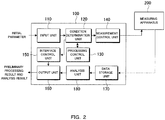
- FIG. 2 is a block diagram showing the configuration of the processing apparatus 100.
- the processing apparatus 100 includes an input unit 110, a condition determination unit 120, a processing control unit 130, a measurement control unit 140, an interface control unit 150, an output unit 160, a data storage unit 170, and an analysis unit 180.
- the input unit 110 receives input from a user. For example, an input of the diffraction angle 2 ⁇ can be received in advance. In addition, an input of each of the distance from the sample S to the two-dimensional detector 230, and size of the detection plane 230a can also be received.
- the scattering vector is represented by k 1 - k 0 , with respect to a wave number vector k 1 of diffracted X-rays and a wave number vector k 0 of incident X-rays.
- a wide range of pole figures can be measured via one-time scanning by carrying out the measurement in a state where the sample S to which the incident X-rays and the diffracted X-rays are arranged symmetrical is tilted in the ⁇ direction.
- the center of the pole figure cannot be measured as it is because the incident angle is changed, thus the center of the pole figure can be measured by tilting the sample S to the incidence side, that is, by shifting ⁇ (as a value larger than a half of 2 ⁇ ) to set an asymmetrical arrangement.
- the pole figure measurement can be performed continuously without overlapping of the range of ⁇ in the pole figure, and the pole figure can be measured with the small number of times of the ⁇ scan, thereby enabling the efficient measurements. Further, the measurement condition does not need to be determined, thereby reducing the burden on a user.
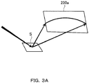
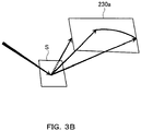
- FIGS. 3A and 3B are diagrams each showing the arrangement of a sample with a two-dimensional detector, and the range which is detectable at a time. As shown in FIG. 3A , the range of ⁇ captured on the detection plane can be measured at a time by using the two-dimensional detector.
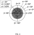
- FIG. 4 is a diagram representing the range which is detectable by the first ⁇ scan on the pole figure.
- the entire range of the pole figure can be provided by measuring ⁇ while varying ⁇ , however as shown in FIG. 3B , the measurable range is changed by ⁇ , because there is a shadow part of the sample S. Taking into account the shadow part, the position of ⁇ in the second or subsequent scan is calculated, thereby enabling the highly efficient measurement without overlapping.
- the angle ⁇ and the angle ⁇ in the first ⁇ scan are first determined so that one end of an arc representing the range of ⁇ detectable at a time on the detection plane, when the rotation angle ⁇ within the sample plane is set to be constant, comes in contact with the position at which ⁇ is 90°. Accordingly, the detection is securely carried out when ⁇ in the pole figure is 90°, and the center of the pole figure can be measured.
- the case where overlapping is made within 1° for ⁇ or 20 pixels is included in that one end of an arc representing the range of ⁇ comes in contact with the position at which ⁇ is 90°.
- one end of an arc representing the range of ⁇ there is a case where pixels expected to be in a detection range partly cut off because of a detection frame, and thus a certain amount of extension of the overlapping as described above becomes necessary.
- ⁇ and ⁇ in the second or subsequent ⁇ scan are determined so that one end of an arc representing the range of ⁇ detectable at a time on the detection plane when ⁇ is set to be constant comes in contact with one end (to take FIG. 4 as an example, the end portion of the circular dark color region) at a time when an arc in an immediately preceding measurement stage is rotated ⁇ rotation. Accordingly, the pole figure measurement can be performed in a short time by reduced ⁇ scan, thereby enabling highly efficient measurements.
- a method for calculating ⁇ and ⁇ will be detailed later.
- the contact state in this case also includes the case where overlapping is made within 1° for ⁇ or 20 pixels.
- Determining ⁇ and ⁇ with the condition determination unit 120 is repeated by the processing control unit 130. As a result of this, the range of ⁇ at each step of ⁇ can be determined. When satisfying the predetermined conditions, repeating thereof is ended. As a result, for example, ⁇ and ⁇ can be determined so that the measurement can be carried out by three times of ⁇ steps, though conventionally four times of ⁇ steps need to be determined.
- the measurement control unit 140 performs the pole figure measurement based on the determined measurement condition. For example, in a case where three times of ⁇ scans are required at a different tilt angle ⁇ , y-axis and x-axis rotation movements of the sample S are carried out for ⁇ and ⁇ which have been determined with respect to each ⁇ scan. Then, the ⁇ scan is carried out by making one rotation around a normal axis of the sample plane while irradiating the sample S with X-rays.
- the interface control unit 150 controls the interface for confirming an input interface and determination results which are provided to a user. For example, the range of ⁇ which is detectable at a time on the detection plane in each ⁇ scan, based on ⁇ and ⁇ which have been determined, is displayed in advance. Thereby, it is possible to visually understand the range of ⁇ in each ⁇ scan when carrying out the measurement under the measurement condition which has been set before the measurement. As a result, the measurement contents can be securely grasped, and the time taken for measuring can be estimated. In that case, it is preferable that the pole figure measured under the calculated conditions is illustrated. Whether the seeking measurement is possible or not under the conditions which have been set can be judged by illustrating the pole figure which is measured under the calculated measurement condition.
- the output unit 160 outputs the interface and so forth for confirming determination results of input and a measurement condition. For example, screen display of the input interface is performed on a display. The display example of an interface screen will be mentioned below. Further, the output unit 160 can also analyze the measurement results of diffracted X-rays and display them.
- the data storage unit 170 stores measurement results obtained by the measuring apparatus 200. That is, intensity of X-rays detected by the two-dimensional detector 230 via each ⁇ scan is stored.
- the analysis unit 180 analyzes X-ray intensity which has been stored to provide the pole figure. Further, orientation of the sample S may be able to be calculated by the resulting pole figure.
- FIG. 5 is a flowchart showing the basic operation of the pole figure measurement system 50.
- the input of the initial parameter is received by GUI (step S1). Specifically, the input of a diffraction angle 2 ⁇ to be measured is received to be set as an initial value.
- the diffraction angle 2 ⁇ is calculated from a material and a measurement index, and may be set as the initial value.
- the distance from the sample S to the detection plane 230a in a case where a value which has been set in the measuring apparatus 200 is maintained, the value maybe used. In a case where a input from a user may be received.
- the position of the detector from the current apparatus state is used.
- the measurement range of the pole figure has been given by default settings, and thus the parameter which has to be decided at least by a user is only the diffraction angle.
- optimum ⁇ and ⁇ are calculated based on the distance from the held sample S to the detection plane 230a, size of the detection plane 230a, and 2 ⁇ (step S2).
- the type of the two-dimensional detector 230 can be recognized by the processing apparatus 100, thereby also enabling acquisition of the size of the detection plane 230a.
- the specific calculation method will be mentioned below.
- step S3 The measurement conditions such as ⁇ , ⁇ and so forth which have been calculated, and the range of the pole figure which can be measured at each ⁇ are displayed (step S3); user's input is received; and whether or not it is determined that there is no problem is judged (step S4). Confirmation and judgement by a user are facilitated by illustration of the measurable pole figure.
- processing returns to step S1.
- the measuring apparatus 200 is controlled under the determined measurement condition, and the sample S is moved to the position of 2 ⁇ which has been set, and each of ⁇ and ⁇ which has been calculated (step S5).
- the ⁇ scan with respect to each ⁇ step is carried out to execute the diffraction measurement (step S6).
- GUI will be detailed later.
- FIG. 7 is a diagram showing a measurement system coordinate.
- a point of the intersection of a detection plane with a normal line of the detection plane passing through the origin o is represented by r, and the distance from the origin o to the detection plane is represented by L (L is equal to the distance between the origin o and the point r).
- L is equal to the distance between the origin o and the point r.
- the detection plane is assumed to be rotated by each of ⁇ and a diffraction angle 2 ⁇ .
- a rotation matrix R w,2 ⁇ in this case is represented by formula (3).
- R ⁇ , 2 ⁇ cos ⁇ ⁇ 2 ⁇ 0 sin ⁇ ⁇ 2 ⁇ 0 1 0 ⁇ sin ⁇ ⁇ 2 ⁇ 0 cos ⁇ ⁇ 2 ⁇
- the detection plane is rectangle and arranged as shown in FIG. 7
- size in the y-axis direction and size in the z-axis direction are represented by w + and w - , and h + and h - , respectively, as shown in formula (4).
- the detection plane is rectangle like the example shown in FIG. 7 , however, it may be circular or elliptical, and may be in any shape.
- the range of ⁇ detectable at a time is different therefrom according to a shape, and thus the shape may be taken into account for the purpose of calculation.
- W + Distance between point r and point w +
- W ⁇ Distance between point r and point w ⁇ H + : Distance between point r and point h + H ⁇ : Distance between point r and point h ⁇
- FIGS. 8A to 8D are diagrams each showing a measurement system coordinate with a sample as the center.
- the unit vector of diffracted X-rays is represented by d. That is, as shown in FIG. 8A , the unit vector d of diffracted X-rays in which X-rays diffracted at the diffraction angle 2 ⁇ within the x-y plane in the direction of z > 0 rotate around incident X-rays i serving as an axis by ⁇ is represented by formula (5).
- d 1 0 0 0 cos ⁇ ⁇ sin ⁇ 0 sin ⁇ cos ⁇ cos 2 ⁇ 0 ⁇ sin 2 ⁇ 0 1 0 sin 2 ⁇ 0 cos 2 ⁇ 1 0 0
- d ⁇ cos ⁇ 0 sin ⁇ 0 1 0 ⁇ sin ⁇ 0 cos ⁇ 1 0 0 0 cos ⁇ ⁇ sin ⁇ 0 sin ⁇ cos ⁇ cos 2 ⁇ 0 ⁇ sin 2 ⁇ 0 1 0 sin 2 ⁇ 0 cos 2 ⁇ 1 0 0
- the unit vector k of the diffraction vector which is represented by incident X-rays i and diffracted X-rays d, is represented by formula (7).
- k d ⁇ i d ⁇ i
- the unit vector k ⁇ of the diffraction vector which is represented by incident X-rays i ⁇ and diffracted X-rays d ⁇ , is represented by formula (8).
- the unit normal vector s ⁇ on the sample plane, which rotates s around the x-axis by ⁇ is represented by formula (10).
- s ⁇ 1 0 0 0 cos ⁇ ⁇ sin ⁇ 0 sin ⁇ cos ⁇ s
- the rotation around the normal line of the sample plane serving as an axis is set to ⁇ .
- FIG. 6 is a flowchart showing the operation of the processing apparatus 100.
- 2 ⁇ , ⁇ min , ⁇ max , and ⁇ kmax are determined (step T1). That is, 2 ⁇ which depends on a sample and plane indices to be measured, and the minimum value ⁇ min in the range of ⁇ to be measured are first determined.
- the ⁇ min determines an arbitrary value under 0 ⁇ ⁇ min ⁇ ⁇ /2.
- ⁇ max cos ⁇ 1 sin ⁇ cos ⁇ k max
- step T2 the unit vectors d a and d b of diffracted X-rays will be calculated.
- d a will be calculated.
- the unit vector d of diffracted X-rays when incident X-rays i have been diffracted at the diffraction angle 2 ⁇ at the origin o is represented by formula (14).
- d cos 2 ⁇ ⁇ sin 2 ⁇ sin ⁇ sin 2 ⁇ cos ⁇
- y(pd) min ⁇ ⁇ L tan 2 ⁇ 1 ⁇ tan 2 2 ⁇ 0 ⁇ 2 ⁇ ⁇ ⁇ 4 , 3 ⁇ 4 ⁇ 2 ⁇ ⁇ ⁇ ⁇ ⁇ ⁇ 4 ⁇ 2 ⁇ ⁇ 3 ⁇ 4
- x(pd) is represented by formula (20).
- x pd L cos 2 2 ⁇ + sin 2 2 ⁇ cos ⁇ a ⁇ cos 2 ⁇
- the range of x(pd) can be calculated as shown in formula (21) from each of H - and H + in size of the detector.
- y(qd) max The maximum value y(qd) max of y(pd) is given as shown in formula (29).
- y qd max ⁇ L tan 2 ⁇ 1 ⁇ tan 2 2 ⁇ 0 ⁇ 2 ⁇ ⁇ ⁇ 4 , 3 ⁇ 4 ⁇ 2 ⁇ ⁇ ⁇ ⁇ ⁇ 4 ⁇ 2 ⁇ ⁇ 3 ⁇ 4
- x (qd) is represented as shown in formula (31).
- x qd L cos 2 2 ⁇ + sin 2 2 ⁇ cos ⁇ b cos 2 ⁇
- ⁇ and ⁇ 0 will be calculated (step T3).
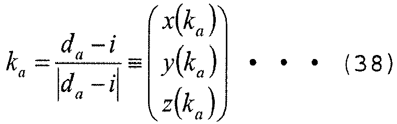
- the unit vector k a of the diffraction vector of diffracted X-rays which have been detected at the point a within a plane of the detector is represented by formula (38).
- k a d a ⁇ i d a ⁇ i ⁇ x k a y k a z k a
- ⁇ tan ⁇ 1 ⁇ x k a z k a
- k a, ⁇ cos ⁇ 0 sin ⁇ 0 1 0 ⁇ sin ⁇ 0 cos ⁇ k a ⁇ x k a , ⁇ y k a , ⁇ z k a , ⁇
- ⁇ 0 tan ⁇ 1 ⁇ y k a , ⁇ z k a , ⁇
- d b, ⁇ and k b, ⁇ are calculated by formulae (42) and (43) (step T4).
- FIGS. 9A to 9D are diagrams each showing the arrangement of a sample with a two-dimensional detector, and the range which is detectable at a time.
- ⁇ k and ⁇ will be calculated (step T6).
- formula (45) needs to be established in order that the unit vector d b, ⁇ of diffracted X-rays may satisfy the appropriate measurement condition.
- the unit vector d c of diffracted X-rays which are diffracted at a diffracted angle 2 ⁇ at the point o, and detected at the point c within a detection plane can be calculated by formula (47).
- the diffraction vector d c, ⁇ that has tilted d c by ⁇ can be calculated by formula (48).
- ⁇ c sin ⁇ 1 cos ⁇ max + sin ⁇ cos 2 ⁇ cos ⁇ sin 2 ⁇ + cos 2 ⁇ cos 2 ⁇ ⁇ tan ⁇ 1 cos ⁇ tan ⁇
- d c, ⁇ From ⁇ c which has been calculated in this way, d c, ⁇ can be determined.
- the unit vector k c, ⁇ of the diffraction vector of diffracted X-rays which have been detected at the point c within a plane of the detector can be calculated by formula (50).
- k c , ⁇ d c , ⁇ ⁇ i ⁇ d c , ⁇ ⁇ i ⁇
- ⁇ k ⁇ cos ⁇ 1 s ⁇ ⁇ k b , ⁇ when cos ⁇ max ⁇ d b , ⁇ ⁇ s ⁇ cos ⁇ 1 s ⁇ ⁇ k c , ⁇ when cos ⁇ max > d b , ⁇ ⁇ s ⁇
- ⁇ ⁇ 0 + ⁇ k
- step T10 the incident angle of incident X-rays is confirmed (step T10). That is, whether or not the angle ⁇ i formed by - i ⁇ and s ⁇ exceeds ⁇ max is determined.
- the ⁇ i is given by formula (55).
- processing directly proceeds to step T12. From the above-described calculation, ⁇ and ⁇ can be calculated.
- the processing carried out by the processing apparatus 100 as described above can be executed by a program.
- FIG. 10 is a diagram showing an example of an interface screen for displaying input and conditions.
- an input region in which a material and its plane indices, or a diffraction angle can be set.
- a region in which the distance between a sample and a detector can be optionally set in this interface screen, which range of the pole figure can be measured at each ⁇ step in the measurement condition which has been calculated can be displayed as a pole figure at the bottom of the screen. As a result, how the pole figure measurement is performed in advance can be confirmed. In addition, necessary measuring time under the measurement condition which has been determined may be calculated and displayed.
Landscapes
- Chemical & Material Sciences (AREA)
- Crystallography & Structural Chemistry (AREA)
- Physics & Mathematics (AREA)
- Health & Medical Sciences (AREA)
- Life Sciences & Earth Sciences (AREA)
- Analytical Chemistry (AREA)
- Biochemistry (AREA)
- General Health & Medical Sciences (AREA)
- General Physics & Mathematics (AREA)
- Immunology (AREA)
- Pathology (AREA)
- Analysing Materials By The Use Of Radiation (AREA)
Abstract
receiving input of a diffraction angle 2θ; and determining an angle ω formed by an incident X-ray and an x-axis, and a tilt angle χ of a sample in each φ scan for a rotation angle φ within a sample plane so as to make a range of an angle α continuous from α = 90° to α = 0° without overlapping, the angle α being formed by the sample plane and a scattering vector, the range of the angle α are detectable at a time on a two-dimensional detection plane in the pole figure measurement at the input angle 2θ, in which determining the angle ω and the angle χ is repeated.
Description
- The present invention relates to a processing method, a processing apparatus and a processing program for determining conditions of a pole figure measurement by X-ray diffraction.
- In the past, in the pole figure measurement using a zero-dimensional detector, as to a tilt angle χ and a rotation angle φ within a sample plane, pole figures have been prepared by measuring the intensity with the χ step and the φ scan. At this time, the intensity measured with χ and φ is expressed as an intensity at the position where α is 90° - χ, and β is φ in the pole figure. That is, the control position on a mechanism is represented by χ, φ and ω, and the position on the pole figure is represented by α and β.
-
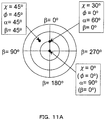
FIG. 11A is a diagram showing the detection range via a zero-dimensional detector when β is set to be constant. As shown in the figure, with the measurement carried out by the zero-dimensional detector, the measurement range obtained by one-time exposure is represented by dots. - In contrast, with the pole figure measurement using a two-dimensional detector, the measurement can be carried out with dots which are continuous in the α direction by one-time exposure (refer to Non-Patent Document 1).
FIG. 11B is a diagram showing the detection range via a two-dimensional detector when φ is set to be constant. As shown in the figure, with the measurement carried out by the two-dimensional detector, the measurement range obtained by one-time exposure is represented by a curve (arc). - As shown in
FIG. 12A , the range within a circle having a certain radius from the center of the pole figure can be measured by being set to χ = 0°, and carrying out the pole figure measurement in which φ scan (0 to 360°) is carried out, using the two-dimensional detector. At this time, the entire range of a pole figure can be prepared by carrying out the φ scan measurement while varying χ in a stepwise manner. - In an example of
FIG. 12B , the measurement is carried out by dividing α into four steps to measure the entire range. The measurement condition needs to be input by the user with the inclusion of to what degree steps are to be taken in such a measurement. - Non-Patent Document 1: Bob B. He, Wiley, Two-dimensional X-ray diffraction, 2009, P226, P229
- With the pole figure measurement using the two-dimensional detector as described above, if a wider range of measurements can be carried out in the first χ step, the number of χ steps can end up with 3, thereby leading to reduction in measuring time. Therefore, a wider range of α can be covered by setting ω to, for example, χ = 30° at the symmetrical arrangement of a half of the diffraction angle (2θ).
- However, at this time, no measurement can be carried out around α = 90° in the pole figure only by simply changing χ, and shifting the measurement range of α. Specifically, it becomes critical that the intensity data around α = 90° cannot be measured, when measuring a sample which is strongly oriented in a normal direction of the sample plane.
- Further, for example, in the system disclosed in
Non-Patent Document 1, a wide range of pole figures are measured at a time and the measuring time is reduced by tilting a sample to measure it in the pole figure measurement using the two-dimensional detector. However, in the example of FIG. 8.7, the center of the pole figure has not been able to be measured.FIG. 13 is a diagram showing the detection range when tilting a sample at χ = 30° and carrying out β scan. As shown inFIG. 13 , blank in a circular measurement is produced at the center of the pole figure. In order to resolve such blank in measurement produced at the center of the pole figure, the conventional method requires trial and error, and therefore a burden on the user becomes large. - The present invention has been made in consideration of such a situation, and has an object to provide a processing method, a processing apparatus and a processing program which can perform pole figure measurement continuously without overlapping of a tilt angle α with the small number of times of the β scan, and enable efficient measurements.
- (1) In order to accomplish the above-described object, the processing method of the present invention is a processing method for determining conditions of pole figure measurement by X-ray diffraction, including the steps of: receiving input of a diffraction angle 2θ; and determining an angle ω formed by an incident X-ray and an x-axis, and a tilt angle χ of a sample in each φ scan for a rotation angle φ within a sample plane so as to make a range of an angle α continuous from α = 90° to α = 0° without overlapping, the angle α being formed by the sample plane and a scattering vector, the range of the angle α are detectable at a time on a two-dimensional detection plane in the pole figure measurement at the input angle 2θ, wherein determining the angle ω and the angle χ is repeated.
Accordingly, the pole figure measurement can be performed continuously without overlapping of the angle α in the pole figure with the small number of times of the φ scan, thereby enabling the efficient measurements. Further, the measurement condition does not need to be determined, thereby reducing the burden on a user. - (2) Further, in the processing method of the present invention, the angle ω and the angle χ in a first φ scan are determined so that one end of an arc representing the range of the angle α that is detectable at a time on the detection plane, when the rotation angle φ within the sample plane is set to be constant, comes in contact with a position at which the angle α is 90°. Accordingly, the detection is securely carried out when the angle α in the pole figure is 90°, and the center of the pole figure can be measured.
- (3) Further, in the processing method of the present invention, the angle ω and the angle χ in a second or subsequent φ scan are determined so that one end of an arc representing the range of the angle α detectable at a time on the detection plane, when the angle φ is set to be constant, comes in contact with one end of an arc in an immediately preceding measurement stage. Therefore, the pole figure measurement can be performed in a short time by reduced number of φ scans, thereby enabling highly efficient measurements.
- (4) Further, in the processing method of the present invention, the range of the angle α detectable at a time on the detection plane in each φ scan is preliminarily displayed, based on the determined angle ω and angle χ. Therefore, the range of the angle α in the each φ scan is visually understood, when carrying out the measurement under the measurement condition which has been set before the measurement. As a result, the measurement contents can be securely grasped, and the time taken for measuring can be estimated.
- (5) Further, the processing apparatus of the present invention is a processing apparatus that determines conditions of pole figure measurement by X-ray diffraction, including: an input unit configured to receive input of a diffraction angle 2θ; a condition determination unit configured to determine an angle ω formed by an incident X-ray and an x-axis, and a tilt angle χ of a sample in each φ scan for a rotation angle φ within a sample plane so as to make a range of an angle α continuous from α = 90° to α = 0° without overlapping, the angle α being formed by the sample plane and a scattering vector, the range of the angle α are detectable at a time on a two-dimensional detection plane in the pole figure measurement at the input angle 2θ; and a processing control unit configured to repeat determining the angle ω and the angle χ. Therefore, the efficient measurement becomes possible, and the burden on a user is reduced.
- (6) Further, the processing program of the present invention is a processing program for determining conditions of pole figure measurement by X-ray diffraction, the processing program causing a computer to execute the processes of: receiving input of a diffraction angle 2θ; and determining an angle ω formed by an incident X-ray and an x-axis, and a tilt angle χ of a sample in each φ scan for a rotation angle φ within a sample plane so as to make a range of an angle α continuous from α = 90° to α = 0° without overlapping, the angle α being formed by the sample plane and a scattering vector, the range of the angle α are detectable at a time on a two-dimensional detection plane in the pole figure measurement at the input angle 2θ, wherein determining the angle ω and the angle χ is repeated. Therefore, the efficient measurement becomes possible, and the burden on a user is reduced.
- According to the present invention, the pole figure measurement can be performed continuously without overlapping of the angle α in the pole figure with the small number of times of the φ scan, thereby enabling efficient measurements. Further, the measurement condition does not need to be determined, thereby reducing the burden on a user.
-
-
FIG. 1 is a schematic diagram showing the configuration of a pole figure measurement system of the present invention. -
FIG. 2 is a block diagram showing the configuration of a processing apparatus of the present invention. -
FIGS. 3A and3B are diagrams each showing the arrangement of a sample with a two-dimensional detector, and the range which is detectable at a time. -
FIG. 4 is a diagram representing the range which is detectable by the first φ scan on a pole figure. -
FIG. 5 is a flowchart showing the basic operation of the pole figure measurement system of the present invention. -
FIG. 6 is a flowchart showing the operation of the processing apparatus of the present invention. -
FIG. 7 is a diagram showing a measurement system coordinate with a sample as the center. -
FIGS. 8A to 8D are diagrams each showing a measurement system coordinate with a sample as the center. -
FIGS. 9A to 9D are diagrams each showing the arrangement of a sample with a two-dimensional detector, and the range which is detectable at a time. -
FIG. 10 is a diagram showing an example of an interface screen for displaying input and conditions. -
FIGS. 11A and11B are diagrams showing the detection ranges when β via a zero-dimensional detector and a two-dimensional detector, respectively, is set to be constant. -
FIGS. 12A and12B are diagrams showing the ranges of φ scan when χ = 0° and when χ is varied in a stepwise manner, respectively. -
FIG. 13 is a diagram showing the detection range when tilting a sample to set χ as an angle of 30°, and carrying out φ scan. - Next, the embodiments of the present invention will be explained while referring to the drawings. In order to facilitate understanding of explanation, in each drawing, the same reference numbers are used with respect to the same constituent elements, and duplicated explanation will be omitted.
-
FIG. 1 is a schematic diagram showing the configuration of a polefigure measurement system 50. The polefigure measurement system 50 includes aprocessing apparatus 100 and a measuringapparatus 200. Theprocessing apparatus 100, which is constituted by a PC, for example, determines the measurement condition; controls the measuringapparatus 200; and analyzes the measurement results. The measuringapparatus 200, which is constituted by anX-ray irradiation unit 210, asample support unit 220, and a two-dimensional detector 230, detects a diffraction image in which incident X-rays irradiated by theX-ray irradiation unit 210 are diffracted by a sample S, using the two-dimensional detector 230. - The two-
dimensional detector 230 can detect diffracted X-rays which are incident on adetection plane 230a. As shown inFIG. 1 , the rotation of thesample support unit 220 is easy to be represented by taking a normal direction of the sample support plane as a z-axis, and setting orthogonal coordinates formed by an x-axis, a y-axis and a z-axis, in which the travel direction of the incident X-rays is included within the x-z plane. - The angle formed by the incident X-ray and the x-axis is expressed as ω, and the angle formed by the incident X-ray and the diffracted X-ray can be expressed as 2θ. When ω = 0°, the incident X-ray travels toward the x-axis. The ω and 2θ can be set independently to each other.
- The χ rotation means rotation of a sample S around the x-axis, and the rotation angle can be represented by χ. The φ rotation means rotation of the sample S around the normal line of the sample plane, and the rotation angle can be represented by φ. The rotation angle χ around the x-axis, the rotation angle ω around the y-axis, and the rotation angle φ around the normal line of the sample plane can be adjusted by the operation of the
sample support unit 220. - The pole
figure measurement system 50 enables efficient pole figure measurement using the two-dimensional detector 230. That is, the center of the pole figure can be measured, and a wide range of pole figure measurements at a time become possible by carrying out the measurement under the measurement condition which has been calculated by theprocessing apparatus 100, whereby the pole figure measurement can be performed efficiently in a short time. Further, the measurement condition is automatically calculated, and is set by theprocessing apparatus 100, and thus the pole figure measurement can be performed with a simple operation. -
FIG. 2 is a block diagram showing the configuration of theprocessing apparatus 100. As shown inFIG. 2 , theprocessing apparatus 100 includes aninput unit 110, acondition determination unit 120, aprocessing control unit 130, ameasurement control unit 140, aninterface control unit 150, anoutput unit 160, adata storage unit 170, and ananalysis unit 180. - The
input unit 110 receives input from a user. For example, an input of the diffraction angle 2θ can be received in advance. In addition, an input of each of the distance from the sample S to the two-dimensional detector 230, and size of thedetection plane 230a can also be received. - The
condition determination unit 120 determines an angle ω formed by the x-axis and the incident X-ray, and a tilt angle χ of a sample in each φ scan for a rotation angle φ within a sample plane so as to make a range of an angle α continuous from α = 90° to α = 0° without overlapping, the angle α being formed by the sample plane and a scattering vector, the range of the angle α is detectable at a time on a two-dimensional detection plane 230a in the pole figure measurement at the input angle 2θ. Being made continuous without overlapping means that as described later, one end of an arc representing the range of the angle α, comes in contact with the center of the pole figure, or one ends of each of arcs representing the range of the angle α come in contact with each other when the φ rotation is carried out. In addition, the scattering vector is represented by k1 - k0, with respect to a wave number vector k1 of diffracted X-rays and a wave number vector k0 of incident X-rays. - A wide range of pole figures can be measured via one-time scanning by carrying out the measurement in a state where the sample S to which the incident X-rays and the diffracted X-rays are arranged symmetrical is tilted in the χ direction. In that case, the center of the pole figure cannot be measured as it is because the incident angle is changed, thus the center of the pole figure can be measured by tilting the sample S to the incidence side, that is, by shifting ω (as a value larger than a half of 2θ) to set an asymmetrical arrangement. Accordingly, the pole figure measurement can be performed continuously without overlapping of the range of α in the pole figure, and the pole figure can be measured with the small number of times of the φ scan, thereby enabling the efficient measurements. Further, the measurement condition does not need to be determined, thereby reducing the burden on a user.
-
FIGS. 3A and3B are diagrams each showing the arrangement of a sample with a two-dimensional detector, and the range which is detectable at a time. As shown inFIG. 3A , the range of α captured on the detection plane can be measured at a time by using the two-dimensional detector. -
FIG. 4 is a diagram representing the range which is detectable by the first φ scan on the pole figure. The entire range of the pole figure can be provided by measuring φ while varying χ, however as shown inFIG. 3B , the measurable range is changed by χ, because there is a shadow part of the sample S. Taking into account the shadow part, the position of χ in the second or subsequent scan is calculated, thereby enabling the highly efficient measurement without overlapping. - Specifically, the angle ω and the angle χ in the first φ scan are first determined so that one end of an arc representing the range of α detectable at a time on the detection plane, when the rotation angle φ within the sample plane is set to be constant, comes in contact with the position at which α is 90°. Accordingly, the detection is securely carried out when α in the pole figure is 90°, and the center of the pole figure can be measured. In addition, the case where overlapping is made within 1° for α or 20 pixels is included in that one end of an arc representing the range of α comes in contact with the position at which α is 90°. In the case of one end of an arc representing the range of α, there is a case where pixels expected to be in a detection range partly cut off because of a detection frame, and thus a certain amount of extension of the overlapping as described above becomes necessary.
- Then, ω and χ in the second or subsequent φ scan are determined so that one end of an arc representing the range of α detectable at a time on the detection plane when φ is set to be constant comes in contact with one end (to take
FIG. 4 as an example, the end portion of the circular dark color region) at a time when an arc in an immediately preceding measurement stage is rotated φ rotation. Accordingly, the pole figure measurement can be performed in a short time by reduced φ scan, thereby enabling highly efficient measurements. A method for calculating ω and χ will be detailed later. The contact state in this case also includes the case where overlapping is made within 1° for α or 20 pixels. - Determining ω and χ with the
condition determination unit 120 is repeated by theprocessing control unit 130. As a result of this, the range of α at each step of χ can be determined. When satisfying the predetermined conditions, repeating thereof is ended. As a result, for example, χ and ω can be determined so that the measurement can be carried out by three times of χ steps, though conventionally four times of χ steps need to be determined. - The
measurement control unit 140 performs the pole figure measurement based on the determined measurement condition. For example, in a case where three times of φ scans are required at a different tilt angle α, y-axis and x-axis rotation movements of the sample S are carried out for ω and χ which have been determined with respect to each φ scan. Then, the φ scan is carried out by making one rotation around a normal axis of the sample plane while irradiating the sample S with X-rays. - The
interface control unit 150 controls the interface for confirming an input interface and determination results which are provided to a user. For example, the range of α which is detectable at a time on the detection plane in each φ scan, based on ω and χ which have been determined, is displayed in advance. Thereby, it is possible to visually understand the range of α in each φ scan when carrying out the measurement under the measurement condition which has been set before the measurement. As a result, the measurement contents can be securely grasped, and the time taken for measuring can be estimated. In that case, it is preferable that the pole figure measured under the calculated conditions is illustrated. Whether the seeking measurement is possible or not under the conditions which have been set can be judged by illustrating the pole figure which is measured under the calculated measurement condition. - The
output unit 160 outputs the interface and so forth for confirming determination results of input and a measurement condition. For example, screen display of the input interface is performed on a display. The display example of an interface screen will be mentioned below. Further, theoutput unit 160 can also analyze the measurement results of diffracted X-rays and display them. - The
data storage unit 170 stores measurement results obtained by the measuringapparatus 200. That is, intensity of X-rays detected by the two-dimensional detector 230 via each φ scan is stored. Theanalysis unit 180 analyzes X-ray intensity which has been stored to provide the pole figure. Further, orientation of the sample S may be able to be calculated by the resulting pole figure. - Next, the operation of the pole
figure measurement system 50 constituted as described above will be described.FIG. 5 is a flowchart showing the basic operation of the polefigure measurement system 50. First, the input of the initial parameter is received by GUI (step S1). Specifically, the input of a diffraction angle 2θ to be measured is received to be set as an initial value. The diffraction angle 2θ is calculated from a material and a measurement index, and may be set as the initial value. As to the distance from the sample S to thedetection plane 230a, in a case where a value which has been set in the measuringapparatus 200 is maintained, the value maybe used. In a case where a input from a user may be received. In a case where no input is received from a user, it is preferable that the position of the detector from the current apparatus state is used. The measurement range of the pole figure has been given by default settings, and thus the parameter which has to be decided at least by a user is only the diffraction angle. - Next, optimum ω and χ are calculated based on the distance from the held sample S to the
detection plane 230a, size of thedetection plane 230a, and 2θ (step S2). The type of the two-dimensional detector 230 can be recognized by theprocessing apparatus 100, thereby also enabling acquisition of the size of thedetection plane 230a. In addition, the specific calculation method will be mentioned below. - The measurement conditions such as ω, χ and so forth which have been calculated, and the range of the pole figure which can be measured at each χ are displayed (step S3); user's input is received; and whether or not it is determined that there is no problem is judged (step S4). Confirmation and judgement by a user are facilitated by illustration of the measurable pole figure.
- In a case where it is judged by a user that there is a problem, processing returns to step S1. In a case where it is judged that there is no problem, the measuring
apparatus 200 is controlled under the determined measurement condition, and the sample S is moved to the position of 2θ which has been set, and each of ω and χ which has been calculated (step S5). The φ scan with respect to each χ step is carried out to execute the diffraction measurement (step S6). In addition, GUI will be detailed later. - Next, in the above-described operations, the operation concerning calculating of ω and χ by the
processing apparatus 100 will be described. First, the definition of each symbol will be described. -
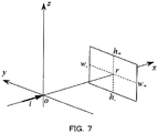
FIG. 7 is a diagram showing a measurement system coordinate. The unit vector i of incident X-rays can be defined by formula (1).
- The unit vector iw which is obtained by rotating i around y-axis by ω is represented by formula (2).

- A point of the intersection of a detection plane with a normal line of the detection plane passing through the origin o is represented by r, and the distance from the origin o to the detection plane is represented by L (L is equal to the distance between the origin o and the point r). When ω = 2, and θ = 0, the point r is positioned on the x-axis.
- The detection plane is assumed to be rotated by each of ω and a diffraction angle 2θ. A rotation matrix Rw,2θ in this case is represented by formula (3).

- In a case where the detection plane is rectangle and arranged as shown in
FIG. 7 , size in the y-axis direction and size in the z-axis direction are represented by w+ and w-, and h+ and h-, respectively, as shown in formula (4). In addition, it is preferable for the purpose of calculation that the detection plane is rectangle like the example shown inFIG. 7 , however, it may be circular or elliptical, and may be in any shape. The range of α detectable at a time is different therefrom according to a shape, and thus the shape may be taken into account for the purpose of calculation.
-
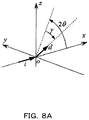
FIGS. 8A to 8D are diagrams each showing a measurement system coordinate with a sample as the center. When incident X-rays i are diffracted at the diffraction angle 2θ at the origin, the unit vector of diffracted X-rays is represented by d. That is, as shown inFIG. 8A , the unit vector d of diffracted X-rays in which X-rays diffracted at the diffraction angle 2θ within the x-y plane in the direction of z > 0 rotate around incident X-rays i serving as an axis by γ is represented by formula (5).
- Further, when incident X-rays iω are diffracted at the diffraction angle 2θ at the origin, the unit vector of diffracted X-rays is represented by formula (6).

- As shown in
FIG. 8B , the unit vector k of the diffraction vector, which is represented by incident X-rays i and diffracted X-rays d, is represented by formula (7).
- Further, as shown in
FIG. 8C , the unit vector kω of the diffraction vector, which is represented by incident X-rays iω and diffracted X-rays dω, is represented by formula (8).
- The unit normal vector s on the sample plane of a flat sample S is represented by formula (9).

- As shown in
FIG. 8D , the unit normal vector sχ on the sample plane, which rotates s around the x-axis by χ is represented by formula (10).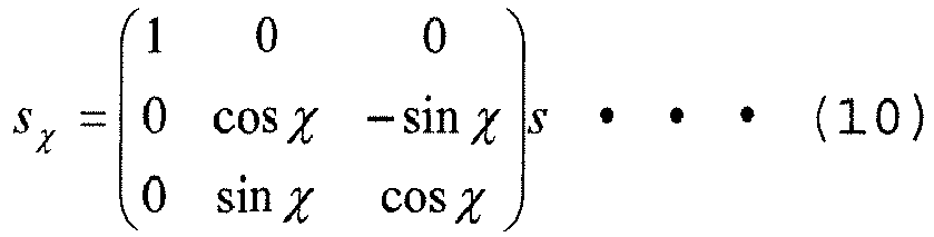
- The angle Ψk formed by the normal line of the sample plane and the diffraction vector is represented by formula (11).

- The rotation around the normal line of the sample plane serving as an axis is set to β.
- Calculation is carried out based on the definition as described above.
FIG. 6 is a flowchart showing the operation of theprocessing apparatus 100. First, 2θ, αmin, Ψmax, and Ψkmax are determined (step T1). That is, 2θ which depends on a sample and plane indices to be measured, and the minimum value αmin in the range of α to be measured are first determined. The αmin determines an arbitrary value under 0 ≤ αmin ≤ π/2. - Then, the maximum value Ψkmax of the angle formed by the unit normal vector sχ of the sample plane and the diffraction vector can be calculated by formula (12).

- The maximum value Ψmax of the angle formed by the unit normal vector sχ of the sample plane and each of incident X-rays and diffracted X-rays can be calculated by formula (13).

- Next, the unit vectors da and db of diffracted X-rays will be calculated (step T2). First, da will be calculated. The unit vector d of diffracted X-rays when incident X-rays i have been diffracted at the diffraction angle 2θ at the origin o is represented by formula (14).

- Formula (15) represents an equation of the detection plane.

- When Pd (p being any number) indicates a point within the detection plane, formula (16) is established.

- In the range of 0 ≤ γ ≤ π, the y component of pd y(pd) always becomes a value of 0 or less as shown in formula (17).

- Then, the minimum value y(pd)min of y(pd) is represented by formula (18).

- Size of the detection plane is limited. In the range, the point within the detection plane, which pd indicates when y (pd) becomes minimal, is represented by a. Further, γ in the case pd indicates the point a is represented by γa. From formula (19), γa in the case y(pd)min = - W+ is established can be calculated.

- On the other hand, x(pd) is represented by formula (20).

- The range of x(pd) can be calculated as shown in formula (21) from each of H- and H+ in size of the detector.

- In addition, when formula (22) is satisfied, the calculation can be carried out as shown in formula (23).


- On the other hand, when formula (24) is satisfied, the calculation can be carried out as shown in formula (25).


- Practically, both of the ranges limited by W+, W- and H+, H- need to be satisfied, and thus a smaller γa between formula (19) and formula (23) or (25) is used to calculate da as described in formula (26).

- Next, the unit vector db of diffracted X-rays will be calculated. When qd (q being any number) indicates a point within the detection plane, formula (27) is established.

- In the range of - π ≤ γ ≤ 0, the y component of qd y(pd) is represented by formula (28), and always takes a value of 0 or more.

- The maximum value y(qd)max of y(pd) is given as shown in formula (29).

- Size of the detection plane is limited. In the range, the point within the detection plane, which qd indicates when y(qd) becomes maximal, is represent by b. Further, γ in the case qd indicates the point b is represented by γb. From formula (30), γb in the case y(qd)max = W-is established can be calculated.

- On the other hand, x (qd) is represented as shown in formula (31).

- The range of x(qd) is represented as shown in formula (32) from each of H- and H+ in size of the detector.

- When formula (33) is satisfied, formula (34) is established.


- On the other hand, when formula (35) is satisfied, formula (36) is established.


- Practically, both of the ranges limited by W+, W-, H+ and H- need to be satisfied, and thus a larger γb is used to calculate db. Then, db is calculated from the resulting γb as shown in formula (37).

- Next, ω and χ0 will be calculated (step T3). The unit vector ka of the diffraction vector of diffracted X-rays which have been detected at the point a within a plane of the detector is represented by formula (38).
- In order to move ka in the y-z plane, the whole is rotated only by ω. The ω in this case can be calculated by formula (39).

- Further, the diffraction vector ka,ω which is tilted at ω can be calculated by formula (40).

- χ0 in the case the orientation of ka,ω is identical to the vector orientation when the unit vector of the z-axis is rotated around the x-axis by χ0 can be calculated by formula (41).

- When carrying out the measurement at ω and χ0 which have been obtained, diffracted X-rays having a normal line of the sample plane as a diffraction vector is detected at the point a within the detection plane.
- Next, db,ω and kb,ω are calculated by formulae (42) and (43) (step T4).


- Then, initial values of χ and n are set by formula (44) (step T5).

- Next, the measurement condition will be determined.
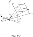
FIGS. 9A to 9D are diagrams each showing the arrangement of a sample with a two-dimensional detector, and the range which is detectable at a time. First, Ψk and α will be calculated (step T6). When calculating Ψk, in the case of incident X-rays iw and the normal line sχ of the sample plane, formula (45) needs to be established in order that the unit vector db,ω of diffracted X-rays may satisfy the appropriate measurement condition.
- When this condition is not satisfied, diffracted X-rays db,ω almost pass through the sample plane, or pass through the sample. When no appropriate measurement condition is satisfied, dc,ω that satisfies formula (46) is determined.

- The unit vector dc of diffracted X-rays which are diffracted at a diffracted angle 2θ at the point o, and detected at the point c within a detection plane can be calculated by formula (47).

- The diffraction vector dc,ω that has tilted dc by ω can be calculated by formula (48).

- When the angle formed by a normal line sχ of the sample plane and dc,ω becomes Ψmax, γc can be calculated by formula (49).

- From γc which has been calculated in this way, dc,ω can be determined. The unit vector kc,ω of the diffraction vector of diffracted X-rays which have been detected at the point c within a plane of the detector can be calculated by formula (50).

- The angle Ψk formed by the diffraction vector which has been able to be measured under the appropriate measurement condition, and a normal line of the sample plane is obtained by formula (51).

- Next, α is calculated by formula (52), and as shown in formula (53), χn and αn (n = 1, 2, 3, ···) are stored (step T7).


- Next, as an end determination, whether or not Ψk = Ψkmax is determined (step T8). As a result of the determination, when Ψk = Ψkmax, the determination of the measurement condition is terminated. When Ψk ≠ Ψkmax, the value χ is updated by formula (54) (step T9).

- Then, the incident angle of incident X-rays is confirmed (step T10). That is, whether or not the angle Ψi formed by - iω and sχ exceeds Ψmax is determined. The Ψi is given by formula (55).

- As a result of the determination, when Ψi exceeds Ψmax, χ is changed so as to give Ψi = Ψmax, as shown in formula (56) (step T11).

- Then, the step number n is updated to n = n + 1 (step T12) and processing returns to step T6. In addition, as a result of the determination of the step T10, when Ψi does not exceed Ψmax, processing directly proceeds to step T12. From the above-described calculation, ω and χ can be calculated. In addition, the processing carried out by the
processing apparatus 100 as described above can be executed by a program. -
FIG. 10 is a diagram showing an example of an interface screen for displaying input and conditions. In an example of the screen, provided is an input region in which a material and its plane indices, or a diffraction angle can be set. Further, also provided is a region in which the distance between a sample and a detector can be optionally set. Further, in this interface screen, which range of the pole figure can be measured at each α step in the measurement condition which has been calculated can be displayed as a pole figure at the bottom of the screen. As a result, how the pole figure measurement is performed in advance can be confirmed. In addition, necessary measuring time under the measurement condition which has been determined may be calculated and displayed. -
- 50 Pole figure measurement system
- 100 Processing apparatus
- 110 Input unit
- 120 Condition determination unit
- 130 Processing control unit
- 140 Measurement control unit
- 150 Interface control unit
- 160 Output unit
- 170 Data storage unit
- 180 Analysis unit
- 200 Measuring apparatus
- 210 X-ray irradiation unit
- 220 Sample support unit
- 230 Two-dimensional detector
- 230a Detection plane
- S Sample
Claims (6)
- A processing method for determining conditions of pole figure measurement by X-ray diffraction, comprising the steps of:receiving input of a diffraction angle 2θ; anddetermining an angle ω formed by an incident X-ray and an x-axis, and a tilt angle χ of a sample in each φ scan for a rotation angle φ within a sample plane so as to make a range of an angle α continuous from α = 90° to α = 0° without overlapping, the angle α being formed by the sample plane and a scattering vector, the range of the angle α are detectable at a time on a two-dimensional detection plane in the pole figure measurement at the input angle 2θ,wherein determining the angle ω and the angle χ is repeated.
- The processing method according to claim 1, wherein the angle ω and the angle χ in a first φ scan are determined so that one end of an arc representing the range of the angle α that is detectable at a time on the detection plane, when the rotation angle φ within the sample plane is set to be constant, comes in contact with a position at which the angle α is 90°.
- The processing method according to claim 1 or 2, wherein the angle ω and the angle χ in a second or subsequent φ scan are determined so that one end of an arc representing the range of the angle α detectable at a time on the detection plane, when the angle φ is set to be constant, comes in contact with one end of an arc in an immediately preceding measurement stage.
- The processing method according to any of claims 1 to 3, wherein the range of the angle α detectable at a time on the detection plane in each φ scan is preliminarily displayed, based on the determined angle ω and angle χ.
- A processing apparatus that determines conditions of pole figure measurement by X-ray diffraction, comprising:an input unit configured to receive input of a diffraction angle 2θ;a condition determination unit configured to determine an angle ω formed by an incident X-ray and an x-axis, and a tilt angle χ of a sample in each φ scan for a rotation angle φ within a sample plane so as to make a range of an angle α continuous from α = 90° to α = 0° without overlapping, the angle α being formed by the sample plane and a scattering vector, the range of the angle α are detectable at a time on a two-dimensional detection plane in the pole figure measurement at the input angle 2θ; anda processing control unit configured to repeat determining the angle ω and the angle χ.
- A processing program for determining conditions of pole figure measurement by X-ray diffraction, the processing program causing a computer to execute the processes of:receiving input of a diffraction angle 2θ; anddetermining an angle ω formed by an incident X-ray and an x-axis, and a tilt angle χ of a sample in each φ scan for a rotation angle φ within a sample plane so as to make a range of an angle α continuous from α = 90° to α = 0° without overlapping, the angle α being formed by the sample plane and a scattering vector, the range of the angle α are detectable at a time on a two-dimensional detection plane in the pole figure measurement at the input angle 2θ,wherein determining the angle ω and the angle χ is repeated.
Applications Claiming Priority (1)
| Application Number | Priority Date | Filing Date | Title |
|---|---|---|---|
| JP2016125248A JP6606706B2 (en) | 2016-06-24 | 2016-06-24 | Processing method, processing apparatus, and processing program |
Publications (2)
| Publication Number | Publication Date |
|---|---|
| EP3260850A1 true EP3260850A1 (en) | 2017-12-27 |
| EP3260850B1 EP3260850B1 (en) | 2022-01-26 |
Family
ID=59101333
Family Applications (1)
| Application Number | Title | Priority Date | Filing Date |
|---|---|---|---|
| EP17177106.6A Active EP3260850B1 (en) | 2016-06-24 | 2017-06-21 | Processing method, processing apparatus and processing program |
Country Status (4)
| Country | Link |
|---|---|
| US (1) | US10876979B2 (en) |
| EP (1) | EP3260850B1 (en) |
| JP (1) | JP6606706B2 (en) |
| CN (1) | CN107543836B (en) |
Cited By (1)
| Publication number | Priority date | Publication date | Assignee | Title |
|---|---|---|---|---|
| CN113865515A (en) * | 2020-06-30 | 2021-12-31 | 中国航发商用航空发动机有限责任公司 | Bearing deflection angle measuring method and tool thereof, and bearing installation quality detection method |
Families Citing this family (4)
| Publication number | Priority date | Publication date | Assignee | Title |
|---|---|---|---|---|
| WO2020235091A1 (en) * | 2019-05-23 | 2020-11-26 | 株式会社日立ハイテク | Charged particle beam device and method for controlling charged particle beam device |
| JP7300718B2 (en) * | 2019-12-13 | 2023-06-30 | 株式会社リガク | Controllers, systems, methods and programs |
| US11555794B1 (en) * | 2021-12-01 | 2023-01-17 | Schaeffler Technologies AG & Co. KG | Method of locating poles on bearing elements |
| JP7834354B2 (en) * | 2023-03-23 | 2026-03-24 | 株式会社リガク | Analysis device, analysis method, and analysis program |
Family Cites Families (45)
| Publication number | Priority date | Publication date | Assignee | Title |
|---|---|---|---|---|
| US7337098B2 (en) * | 1998-05-18 | 2008-02-26 | Rigaku Corporation | Diffraction condition simulation device, diffraction measurement system, and crystal analysis system |
| JP3944330B2 (en) * | 1999-04-12 | 2007-07-11 | 株式会社リガク | X-ray diffractometer and method for measuring X-ray rocking curve |
| US6937694B2 (en) * | 1999-06-10 | 2005-08-30 | Rigaku Corporation | Pole measuring method |
| US6301330B1 (en) * | 1999-07-30 | 2001-10-09 | Hypernex, Inc. | Apparatus and method for texture analysis on semiconductor wafers |
| US6882739B2 (en) * | 2001-06-19 | 2005-04-19 | Hypernex, Inc. | Method and apparatus for rapid grain size analysis of polycrystalline materials |
| JP3726080B2 (en) * | 2002-05-23 | 2005-12-14 | 株式会社リガク | Method for evaluating orientation of polycrystalline materials |
| US6678347B1 (en) * | 2002-07-26 | 2004-01-13 | Hypernex, Inc. | Method and apparatus for quantitative phase analysis of textured polycrystalline materials |
| US6792075B2 (en) * | 2002-08-21 | 2004-09-14 | Hypernex, Inc. | Method and apparatus for thin film thickness mapping |
| JP3697246B2 (en) * | 2003-03-26 | 2005-09-21 | 株式会社リガク | X-ray diffractometer |
| JP3691827B2 (en) * | 2003-05-29 | 2005-09-07 | 株式会社リガク | How to set the reciprocal grid map measurement range |
| JP3697251B2 (en) * | 2003-05-29 | 2005-09-21 | 株式会社リガク | Dynamic display method of scattering vector of X-ray diffraction |
| WO2005010512A1 (en) * | 2003-07-22 | 2005-02-03 | X-Ray Optical Systems, Inc. | Method and system for x-ray diffraction measurements using an aligned source and detector rotating around a sample surface |
| JP3904543B2 (en) * | 2003-10-14 | 2007-04-11 | 株式会社リガク | X-ray crystal orientation measuring apparatus and X-ray crystal orientation measuring method |
| JP4003968B2 (en) * | 2004-02-27 | 2007-11-07 | 株式会社リガク | X-ray analyzer |
| CN1257403C (en) * | 2004-03-30 | 2006-05-24 | 北京科技大学 | A Method for Detecting Pole Figures of Metal Sheets Using Two-Dimensional Diffraction |
| JP4565546B2 (en) * | 2004-04-09 | 2010-10-20 | 株式会社リガク | X-ray analysis method and X-ray analysis apparatus |
| JP3919775B2 (en) * | 2004-07-15 | 2007-05-30 | 株式会社リガク | X-ray reflectivity measuring method and apparatus |
| US7190762B2 (en) * | 2004-10-29 | 2007-03-13 | Broker Axs, Inc | Scanning line detector for two-dimensional x-ray diffractometer |
| CN100501959C (en) * | 2005-04-20 | 2009-06-17 | 吉林大学 | Method for detecting hetero-epitaxial film crystal lattice orientation by utilizing a diffractometer |
| JP4277826B2 (en) * | 2005-06-23 | 2009-06-10 | 住友電気工業株式会社 | Nitride crystal, nitride crystal substrate, nitride crystal substrate with epi layer, and semiconductor device and method for manufacturing the same |
| US8771552B2 (en) * | 2005-06-23 | 2014-07-08 | Sumitomo Electric Industries, Ltd. | Group III nitride crystal substrate, epilayer-containing group III nitride crystal substrate, semiconductor device and method of manufacturing the same |
| JP4685877B2 (en) * | 2005-11-02 | 2011-05-18 | 株式会社リガク | Method and apparatus for measuring orientation distribution of microcrystalline grains |
| WO2007078023A1 (en) * | 2006-01-06 | 2007-07-12 | Postech Foundation | Characterization of three-dimensional distribution of defects by x-ray topography |
| JP4278108B2 (en) * | 2006-07-07 | 2009-06-10 | 株式会社リガク | Ultra-small angle X-ray scattering measurement device |
| US7443952B2 (en) * | 2006-10-06 | 2008-10-28 | Rigaku Corporation | X-ray diffraction measurement method and X-ray diffraction apparatus |
| US7789977B2 (en) * | 2006-10-26 | 2010-09-07 | Hitachi Cable, Ltd. | Rolled copper foil and manufacturing method thereof |
| US7801272B2 (en) * | 2007-09-28 | 2010-09-21 | Rigaku Corporation | X-ray diffraction apparatus and X-ray diffraction method |
| US7646847B2 (en) * | 2008-05-01 | 2010-01-12 | Bruker Axs Inc. | Handheld two-dimensional X-ray diffractometer |
| JP4971383B2 (en) * | 2009-03-25 | 2012-07-11 | 株式会社リガク | X-ray diffraction method and X-ray diffraction apparatus |
| US8111807B2 (en) * | 2009-09-16 | 2012-02-07 | Rigaku Corporation | Crystallite size analysis method and apparatus using powder X-ray diffraction |
| JP5516364B2 (en) * | 2010-11-22 | 2014-06-11 | 住友電気工業株式会社 | X-ray diffractometer, data analysis method for X-ray diffractometer, control method for X-ray diffractometer, and program for realizing the method |
| US8903044B2 (en) * | 2011-01-31 | 2014-12-02 | Rigaku Corporation | X-ray diffraction apparatus |
| JP5511020B2 (en) * | 2011-11-24 | 2014-06-04 | 株式会社リガク | X-ray analyzer |
| JP5959057B2 (en) * | 2011-11-29 | 2016-08-02 | 株式会社リガク | X-ray analyzer |
| GB2497170B (en) * | 2011-11-29 | 2018-02-21 | Rigaku Denki Co Ltd | X-ray analysis apparatus |
| JP5871393B2 (en) * | 2011-11-29 | 2016-03-01 | 株式会社リガク | X-ray analyzer |
| CN103364416B (en) * | 2012-04-01 | 2016-03-09 | 中国科学院高能物理研究所 | X ray differential phase micro imaging system and formation method |
| CN102661963B (en) * | 2012-06-01 | 2014-02-12 | 吉林大学 | Special X-ray diffraction and scattering analysis device for fiber material |
| JP5713357B2 (en) * | 2012-07-25 | 2015-05-07 | 株式会社リガク | X-ray stress measurement method and apparatus |
| EP2818851B1 (en) * | 2013-06-26 | 2023-07-26 | Malvern Panalytical B.V. | Diffraction Imaging |
| US9835570B2 (en) * | 2013-09-13 | 2017-12-05 | The United States Of America As Represented By The Administrator Of Nasa | X-ray diffraction (XRD) characterization methods for sigma=3 twin defects in cubic semiconductor (100) wafers |
| JP6270214B2 (en) * | 2013-11-25 | 2018-01-31 | 株式会社リガク | Optical axis adjustment method for X-ray analyzer and X-ray analyzer |
| CN104062311B (en) * | 2014-05-23 | 2017-01-18 | 武汉钢铁(集团)公司 | Method for measuring inverse pole figure by inclining and rotating test sample |
| US9897559B2 (en) * | 2015-12-22 | 2018-02-20 | Bruker Axs, Inc. | Method for collecting accurate X-ray diffraction data with a scanning two-dimensional detector |
| US10295484B2 (en) * | 2017-04-05 | 2019-05-21 | Bruker Axs, Inc. | Method and apparatus for extending angular coverage for a scanning two-dimensional X-ray detector |
-
2016
- 2016-06-24 JP JP2016125248A patent/JP6606706B2/en active Active
-
2017
- 2017-06-09 US US15/618,433 patent/US10876979B2/en active Active
- 2017-06-21 EP EP17177106.6A patent/EP3260850B1/en active Active
- 2017-06-23 CN CN201710491214.7A patent/CN107543836B/en active Active
Non-Patent Citations (2)
| Title |
|---|
| "Two-Dimensional X-Ray Diffraction", 12 November 2009, WILEY, ISBN: 978-0-470-22722-0, article BOB B HE: "Two-Dimensional X-Ray Diffraction", pages: 218 - 248, XP055411189, DOI: 10.1002/9780470502648 * |
| BOB B. HE; WILEY, TWO-DIMENSIONAL X-RAY DIFFRACTION, 2009, pages 226,229 |
Cited By (2)
| Publication number | Priority date | Publication date | Assignee | Title |
|---|---|---|---|---|
| CN113865515A (en) * | 2020-06-30 | 2021-12-31 | 中国航发商用航空发动机有限责任公司 | Bearing deflection angle measuring method and tool thereof, and bearing installation quality detection method |
| CN113865515B (en) * | 2020-06-30 | 2023-11-10 | 中国航发商用航空发动机有限责任公司 | Bearing deflection angle measuring method and tool thereof, and bearing installation quality detecting method |
Also Published As
| Publication number | Publication date |
|---|---|
| JP6606706B2 (en) | 2019-11-20 |
| CN107543836A (en) | 2018-01-05 |
| US10876979B2 (en) | 2020-12-29 |
| EP3260850B1 (en) | 2022-01-26 |
| JP2017227586A (en) | 2017-12-28 |
| CN107543836B (en) | 2021-10-26 |
| US20170370860A1 (en) | 2017-12-28 |
Similar Documents
| Publication | Publication Date | Title |
|---|---|---|
| EP3260850A1 (en) | Processing method, processing apparatus and processing program | |
| US8224110B2 (en) | Image processing apparatus and image processing method | |
| JP5511020B2 (en) | X-ray analyzer | |
| JP6497784B2 (en) | Crystal phase identification method, crystal phase identification apparatus, and X-ray diffraction measurement system | |
| EP2256780B1 (en) | Transmission electron microscope with electronic spectroscope and method of displaying spectral image | |
| US20250003742A1 (en) | Enhanced cross sectional features measurement methodology | |
| DE102014211948A1 (en) | System and method for the selective determination of point clouds | |
| Alpers et al. | Geometric reconstruction methods for electron tomography | |
| US20190035597A1 (en) | Scanning electron microscope and image processing apparatus | |
| JP7747104B2 (en) | surface analysis device | |
| US20100226579A1 (en) | Image processing method and apparatus for detecting an edge of an object within an image | |
| DE102013220470A1 (en) | SYSTEM AND METHOD FOR SELECTING AND DISPLAYING SEGMENTATION PARAMETERS FOR AN OPTICAL CHARACTER DETECTION | |
| US10755396B2 (en) | Image forming apparatus | |
| JP3691827B2 (en) | How to set the reciprocal grid map measurement range | |
| EP3300099A1 (en) | Methods for calibration of a quadrupole mass filter | |
| EP2453409B1 (en) | Edge diversity object detection | |
| EP1970936A2 (en) | Image forming method and electron microscope | |
| US12046446B2 (en) | Charged particle beam device | |
| JP5407887B2 (en) | Display processing device for X-ray analysis | |
| JP2003014663A (en) | Method and apparatus for analyzing irregular density sample as well as system therefor | |
| US20220307995A1 (en) | X-ray diffraction measurement apparatus and method | |
| US20210005290A1 (en) | Adaptive lane detection systems and methods | |
| JP2008116206A (en) | Pattern dimension measuring apparatus, method and program | |
| De Backer et al. | Modelling ADF STEM images using elliptical Gaussian peaks and its effects on the quantification of structure parameters in the presence of sample tilt | |
| EP2453410A2 (en) | Approximation of an imaged object from edges detected from the underlying image |
Legal Events
| Date | Code | Title | Description |
|---|---|---|---|
| PUAI | Public reference made under article 153(3) epc to a published international application that has entered the european phase |
Free format text: ORIGINAL CODE: 0009012 |
|
| STAA | Information on the status of an ep patent application or granted ep patent |
Free format text: STATUS: THE APPLICATION HAS BEEN PUBLISHED |
|
| AK | Designated contracting states |
Kind code of ref document: A1 Designated state(s): AL AT BE BG CH CY CZ DE DK EE ES FI FR GB GR HR HU IE IS IT LI LT LU LV MC MK MT NL NO PL PT RO RS SE SI SK SM TR |
|
| AX | Request for extension of the european patent |
Extension state: BA ME |
|
| STAA | Information on the status of an ep patent application or granted ep patent |
Free format text: STATUS: REQUEST FOR EXAMINATION WAS MADE |
|
| 17P | Request for examination filed |
Effective date: 20180625 |
|
| RBV | Designated contracting states (corrected) |
Designated state(s): AL AT BE BG CH CY CZ DE DK EE ES FI FR GB GR HR HU IE IS IT LI LT LU LV MC MK MT NL NO PL PT RO RS SE SI SK SM TR |
|
| STAA | Information on the status of an ep patent application or granted ep patent |
Free format text: STATUS: EXAMINATION IS IN PROGRESS |
|
| 17Q | First examination report despatched |
Effective date: 20200513 |
|
| GRAP | Despatch of communication of intention to grant a patent |
Free format text: ORIGINAL CODE: EPIDOSNIGR1 |
|
| STAA | Information on the status of an ep patent application or granted ep patent |
Free format text: STATUS: GRANT OF PATENT IS INTENDED |
|
| INTG | Intention to grant announced |
Effective date: 20210816 |
|
| GRAS | Grant fee paid |
Free format text: ORIGINAL CODE: EPIDOSNIGR3 |
|
| GRAA | (expected) grant |
Free format text: ORIGINAL CODE: 0009210 |
|
| STAA | Information on the status of an ep patent application or granted ep patent |
Free format text: STATUS: THE PATENT HAS BEEN GRANTED |
|
| AK | Designated contracting states |
Kind code of ref document: B1 Designated state(s): AL AT BE BG CH CY CZ DE DK EE ES FI FR GB GR HR HU IE IS IT LI LT LU LV MC MK MT NL NO PL PT RO RS SE SI SK SM TR |
|
| REG | Reference to a national code |
Ref country code: GB Ref legal event code: FG4D |
|
| REG | Reference to a national code |
Ref country code: CH Ref legal event code: EP |
|
| REG | Reference to a national code |
Ref country code: AT Ref legal event code: REF Ref document number: 1465659 Country of ref document: AT Kind code of ref document: T Effective date: 20220215 |
|
| REG | Reference to a national code |
Ref country code: IE Ref legal event code: FG4D |
|
| REG | Reference to a national code |
Ref country code: DE Ref legal event code: R096 Ref document number: 602017052680 Country of ref document: DE |
|
| REG | Reference to a national code |
Ref country code: NL Ref legal event code: FP |
|
| REG | Reference to a national code |
Ref country code: LT Ref legal event code: MG9D |
|
| REG | Reference to a national code |
Ref country code: AT Ref legal event code: MK05 Ref document number: 1465659 Country of ref document: AT Kind code of ref document: T Effective date: 20220126 |
|
| PG25 | Lapsed in a contracting state [announced via postgrant information from national office to epo] |
Ref country code: SE Free format text: LAPSE BECAUSE OF FAILURE TO SUBMIT A TRANSLATION OF THE DESCRIPTION OR TO PAY THE FEE WITHIN THE PRESCRIBED TIME-LIMIT Effective date: 20220126 Ref country code: RS Free format text: LAPSE BECAUSE OF FAILURE TO SUBMIT A TRANSLATION OF THE DESCRIPTION OR TO PAY THE FEE WITHIN THE PRESCRIBED TIME-LIMIT Effective date: 20220126 Ref country code: PT Free format text: LAPSE BECAUSE OF FAILURE TO SUBMIT A TRANSLATION OF THE DESCRIPTION OR TO PAY THE FEE WITHIN THE PRESCRIBED TIME-LIMIT Effective date: 20220526 Ref country code: NO Free format text: LAPSE BECAUSE OF FAILURE TO SUBMIT A TRANSLATION OF THE DESCRIPTION OR TO PAY THE FEE WITHIN THE PRESCRIBED TIME-LIMIT Effective date: 20220426 Ref country code: LT Free format text: LAPSE BECAUSE OF FAILURE TO SUBMIT A TRANSLATION OF THE DESCRIPTION OR TO PAY THE FEE WITHIN THE PRESCRIBED TIME-LIMIT Effective date: 20220126 Ref country code: HR Free format text: LAPSE BECAUSE OF FAILURE TO SUBMIT A TRANSLATION OF THE DESCRIPTION OR TO PAY THE FEE WITHIN THE PRESCRIBED TIME-LIMIT Effective date: 20220126 Ref country code: ES Free format text: LAPSE BECAUSE OF FAILURE TO SUBMIT A TRANSLATION OF THE DESCRIPTION OR TO PAY THE FEE WITHIN THE PRESCRIBED TIME-LIMIT Effective date: 20220126 Ref country code: BG Free format text: LAPSE BECAUSE OF FAILURE TO SUBMIT A TRANSLATION OF THE DESCRIPTION OR TO PAY THE FEE WITHIN THE PRESCRIBED TIME-LIMIT Effective date: 20220426 |
|
| PG25 | Lapsed in a contracting state [announced via postgrant information from national office to epo] |
Ref country code: PL Free format text: LAPSE BECAUSE OF FAILURE TO SUBMIT A TRANSLATION OF THE DESCRIPTION OR TO PAY THE FEE WITHIN THE PRESCRIBED TIME-LIMIT Effective date: 20220126 Ref country code: LV Free format text: LAPSE BECAUSE OF FAILURE TO SUBMIT A TRANSLATION OF THE DESCRIPTION OR TO PAY THE FEE WITHIN THE PRESCRIBED TIME-LIMIT Effective date: 20220126 Ref country code: GR Free format text: LAPSE BECAUSE OF FAILURE TO SUBMIT A TRANSLATION OF THE DESCRIPTION OR TO PAY THE FEE WITHIN THE PRESCRIBED TIME-LIMIT Effective date: 20220427 Ref country code: FI Free format text: LAPSE BECAUSE OF FAILURE TO SUBMIT A TRANSLATION OF THE DESCRIPTION OR TO PAY THE FEE WITHIN THE PRESCRIBED TIME-LIMIT Effective date: 20220126 Ref country code: AT Free format text: LAPSE BECAUSE OF FAILURE TO SUBMIT A TRANSLATION OF THE DESCRIPTION OR TO PAY THE FEE WITHIN THE PRESCRIBED TIME-LIMIT Effective date: 20220126 |
|
| PG25 | Lapsed in a contracting state [announced via postgrant information from national office to epo] |
Ref country code: IS Free format text: LAPSE BECAUSE OF FAILURE TO SUBMIT A TRANSLATION OF THE DESCRIPTION OR TO PAY THE FEE WITHIN THE PRESCRIBED TIME-LIMIT Effective date: 20220526 |
|
| REG | Reference to a national code |
Ref country code: DE Ref legal event code: R097 Ref document number: 602017052680 Country of ref document: DE |
|
| PG25 | Lapsed in a contracting state [announced via postgrant information from national office to epo] |
Ref country code: SM Free format text: LAPSE BECAUSE OF FAILURE TO SUBMIT A TRANSLATION OF THE DESCRIPTION OR TO PAY THE FEE WITHIN THE PRESCRIBED TIME-LIMIT Effective date: 20220126 Ref country code: SK Free format text: LAPSE BECAUSE OF FAILURE TO SUBMIT A TRANSLATION OF THE DESCRIPTION OR TO PAY THE FEE WITHIN THE PRESCRIBED TIME-LIMIT Effective date: 20220126 Ref country code: RO Free format text: LAPSE BECAUSE OF FAILURE TO SUBMIT A TRANSLATION OF THE DESCRIPTION OR TO PAY THE FEE WITHIN THE PRESCRIBED TIME-LIMIT Effective date: 20220126 Ref country code: EE Free format text: LAPSE BECAUSE OF FAILURE TO SUBMIT A TRANSLATION OF THE DESCRIPTION OR TO PAY THE FEE WITHIN THE PRESCRIBED TIME-LIMIT Effective date: 20220126 Ref country code: DK Free format text: LAPSE BECAUSE OF FAILURE TO SUBMIT A TRANSLATION OF THE DESCRIPTION OR TO PAY THE FEE WITHIN THE PRESCRIBED TIME-LIMIT Effective date: 20220126 Ref country code: CZ Free format text: LAPSE BECAUSE OF FAILURE TO SUBMIT A TRANSLATION OF THE DESCRIPTION OR TO PAY THE FEE WITHIN THE PRESCRIBED TIME-LIMIT Effective date: 20220126 |
|
| PG25 | Lapsed in a contracting state [announced via postgrant information from national office to epo] |
Ref country code: AL Free format text: LAPSE BECAUSE OF FAILURE TO SUBMIT A TRANSLATION OF THE DESCRIPTION OR TO PAY THE FEE WITHIN THE PRESCRIBED TIME-LIMIT Effective date: 20220126 |
|
| PLBE | No opposition filed within time limit |
Free format text: ORIGINAL CODE: 0009261 |
|
| STAA | Information on the status of an ep patent application or granted ep patent |
Free format text: STATUS: NO OPPOSITION FILED WITHIN TIME LIMIT |
|
| 26N | No opposition filed |
Effective date: 20221027 |
|
| PG25 | Lapsed in a contracting state [announced via postgrant information from national office to epo] |
Ref country code: MC Free format text: LAPSE BECAUSE OF FAILURE TO SUBMIT A TRANSLATION OF THE DESCRIPTION OR TO PAY THE FEE WITHIN THE PRESCRIBED TIME-LIMIT Effective date: 20220126 |
|
| REG | Reference to a national code |
Ref country code: CH Ref legal event code: PL |
|
| REG | Reference to a national code |
Ref country code: BE Ref legal event code: MM Effective date: 20220630 |
|
| PG25 | Lapsed in a contracting state [announced via postgrant information from national office to epo] |
Ref country code: SI Free format text: LAPSE BECAUSE OF FAILURE TO SUBMIT A TRANSLATION OF THE DESCRIPTION OR TO PAY THE FEE WITHIN THE PRESCRIBED TIME-LIMIT Effective date: 20220126 |
|
| GBPC | Gb: european patent ceased through non-payment of renewal fee |
Effective date: 20220621 |
|
| PG25 | Lapsed in a contracting state [announced via postgrant information from national office to epo] |
Ref country code: LU Free format text: LAPSE BECAUSE OF NON-PAYMENT OF DUE FEES Effective date: 20220621 Ref country code: LI Free format text: LAPSE BECAUSE OF NON-PAYMENT OF DUE FEES Effective date: 20220630 Ref country code: IE Free format text: LAPSE BECAUSE OF NON-PAYMENT OF DUE FEES Effective date: 20220621 Ref country code: FR Free format text: LAPSE BECAUSE OF NON-PAYMENT OF DUE FEES Effective date: 20220630 Ref country code: CH Free format text: LAPSE BECAUSE OF NON-PAYMENT OF DUE FEES Effective date: 20220630 |
|
| PG25 | Lapsed in a contracting state [announced via postgrant information from national office to epo] |
Ref country code: GB Free format text: LAPSE BECAUSE OF NON-PAYMENT OF DUE FEES Effective date: 20220621 Ref country code: BE Free format text: LAPSE BECAUSE OF NON-PAYMENT OF DUE FEES Effective date: 20220630 |
|
| PG25 | Lapsed in a contracting state [announced via postgrant information from national office to epo] |
Ref country code: IT Free format text: LAPSE BECAUSE OF FAILURE TO SUBMIT A TRANSLATION OF THE DESCRIPTION OR TO PAY THE FEE WITHIN THE PRESCRIBED TIME-LIMIT Effective date: 20220126 |
|
| PG25 | Lapsed in a contracting state [announced via postgrant information from national office to epo] |
Ref country code: HU Free format text: LAPSE BECAUSE OF FAILURE TO SUBMIT A TRANSLATION OF THE DESCRIPTION OR TO PAY THE FEE WITHIN THE PRESCRIBED TIME-LIMIT; INVALID AB INITIO Effective date: 20170621 |
|
| PG25 | Lapsed in a contracting state [announced via postgrant information from national office to epo] |
Ref country code: MK Free format text: LAPSE BECAUSE OF FAILURE TO SUBMIT A TRANSLATION OF THE DESCRIPTION OR TO PAY THE FEE WITHIN THE PRESCRIBED TIME-LIMIT Effective date: 20220126 Ref country code: CY Free format text: LAPSE BECAUSE OF FAILURE TO SUBMIT A TRANSLATION OF THE DESCRIPTION OR TO PAY THE FEE WITHIN THE PRESCRIBED TIME-LIMIT Effective date: 20220126 |
|
| PG25 | Lapsed in a contracting state [announced via postgrant information from national office to epo] |
Ref country code: TR Free format text: LAPSE BECAUSE OF FAILURE TO SUBMIT A TRANSLATION OF THE DESCRIPTION OR TO PAY THE FEE WITHIN THE PRESCRIBED TIME-LIMIT Effective date: 20220126 |
|
| PG25 | Lapsed in a contracting state [announced via postgrant information from national office to epo] |
Ref country code: MT Free format text: LAPSE BECAUSE OF FAILURE TO SUBMIT A TRANSLATION OF THE DESCRIPTION OR TO PAY THE FEE WITHIN THE PRESCRIBED TIME-LIMIT Effective date: 20220126 |
|
| PGFP | Annual fee paid to national office [announced via postgrant information from national office to epo] |
Ref country code: DE Payment date: 20250618 Year of fee payment: 9 |
|
| PGFP | Annual fee paid to national office [announced via postgrant information from national office to epo] |
Ref country code: NL Payment date: 20250618 Year of fee payment: 9 |