EP3260773B1 - Flipping installation device for led strip lighting - Google Patents
Flipping installation device for led strip lighting Download PDFInfo
- Publication number
- EP3260773B1 EP3260773B1 EP17176665.2A EP17176665A EP3260773B1 EP 3260773 B1 EP3260773 B1 EP 3260773B1 EP 17176665 A EP17176665 A EP 17176665A EP 3260773 B1 EP3260773 B1 EP 3260773B1
- Authority
- EP
- European Patent Office
- Prior art keywords
- house
- installation frame
- link
- led strip
- flipping
- Prior art date
- Legal status (The legal status is an assumption and is not a legal conclusion. Google has not performed a legal analysis and makes no representation as to the accuracy of the status listed.)
- Active
Links
Images

Classifications
-
- F—MECHANICAL ENGINEERING; LIGHTING; HEATING; WEAPONS; BLASTING
- F21—LIGHTING
- F21V—FUNCTIONAL FEATURES OR DETAILS OF LIGHTING DEVICES OR SYSTEMS THEREOF; STRUCTURAL COMBINATIONS OF LIGHTING DEVICES WITH OTHER ARTICLES, NOT OTHERWISE PROVIDED FOR
- F21V21/00—Supporting, suspending, or attaching arrangements for lighting devices; Hand grips
- F21V21/14—Adjustable mountings
-
- F—MECHANICAL ENGINEERING; LIGHTING; HEATING; WEAPONS; BLASTING
- F21—LIGHTING
- F21S—NON-PORTABLE LIGHTING DEVICES; SYSTEMS THEREOF; VEHICLE LIGHTING DEVICES SPECIALLY ADAPTED FOR VEHICLE EXTERIORS
- F21S4/00—Lighting devices or systems using a string or strip of light sources
- F21S4/20—Lighting devices or systems using a string or strip of light sources with light sources held by or within elongate supports
- F21S4/28—Lighting devices or systems using a string or strip of light sources with light sources held by or within elongate supports rigid, e.g. LED bars
-
- F—MECHANICAL ENGINEERING; LIGHTING; HEATING; WEAPONS; BLASTING
- F21—LIGHTING
- F21S—NON-PORTABLE LIGHTING DEVICES; SYSTEMS THEREOF; VEHICLE LIGHTING DEVICES SPECIALLY ADAPTED FOR VEHICLE EXTERIORS
- F21S8/00—Lighting devices intended for fixed installation
- F21S8/02—Lighting devices intended for fixed installation of recess-mounted type, e.g. downlighters
- F21S8/026—Lighting devices intended for fixed installation of recess-mounted type, e.g. downlighters intended to be recessed in a ceiling or like overhead structure, e.g. suspended ceiling
-
- F—MECHANICAL ENGINEERING; LIGHTING; HEATING; WEAPONS; BLASTING
- F21—LIGHTING
- F21V—FUNCTIONAL FEATURES OR DETAILS OF LIGHTING DEVICES OR SYSTEMS THEREOF; STRUCTURAL COMBINATIONS OF LIGHTING DEVICES WITH OTHER ARTICLES, NOT OTHERWISE PROVIDED FOR
- F21V17/00—Fastening of component parts of lighting devices, e.g. shades, globes, refractors, reflectors, filters, screens, grids or protective cages
- F21V17/10—Fastening of component parts of lighting devices, e.g. shades, globes, refractors, reflectors, filters, screens, grids or protective cages characterised by specific fastening means or way of fastening
- F21V17/16—Fastening of component parts of lighting devices, e.g. shades, globes, refractors, reflectors, filters, screens, grids or protective cages characterised by specific fastening means or way of fastening by deformation of parts; Snap action mounting
- F21V17/164—Fastening of component parts of lighting devices, e.g. shades, globes, refractors, reflectors, filters, screens, grids or protective cages characterised by specific fastening means or way of fastening by deformation of parts; Snap action mounting the parts being subjected to bending, e.g. snap joints
-
- F—MECHANICAL ENGINEERING; LIGHTING; HEATING; WEAPONS; BLASTING
- F21—LIGHTING
- F21V—FUNCTIONAL FEATURES OR DETAILS OF LIGHTING DEVICES OR SYSTEMS THEREOF; STRUCTURAL COMBINATIONS OF LIGHTING DEVICES WITH OTHER ARTICLES, NOT OTHERWISE PROVIDED FOR
- F21V21/00—Supporting, suspending, or attaching arrangements for lighting devices; Hand grips
- F21V21/02—Wall, ceiling, or floor bases; Fixing pendants or arms to the bases
- F21V21/025—Elongated bases having a U-shaped cross section
-
- F—MECHANICAL ENGINEERING; LIGHTING; HEATING; WEAPONS; BLASTING
- F21—LIGHTING
- F21V—FUNCTIONAL FEATURES OR DETAILS OF LIGHTING DEVICES OR SYSTEMS THEREOF; STRUCTURAL COMBINATIONS OF LIGHTING DEVICES WITH OTHER ARTICLES, NOT OTHERWISE PROVIDED FOR
- F21V21/00—Supporting, suspending, or attaching arrangements for lighting devices; Hand grips
- F21V21/02—Wall, ceiling, or floor bases; Fixing pendants or arms to the bases
- F21V21/04—Recessed bases
- F21V21/049—Mounting arrangements for attaching lighting devices to the ceiling, the lighting devices being recessed in a false or stretched ceiling
-
- F—MECHANICAL ENGINEERING; LIGHTING; HEATING; WEAPONS; BLASTING
- F21—LIGHTING
- F21V—FUNCTIONAL FEATURES OR DETAILS OF LIGHTING DEVICES OR SYSTEMS THEREOF; STRUCTURAL COMBINATIONS OF LIGHTING DEVICES WITH OTHER ARTICLES, NOT OTHERWISE PROVIDED FOR
- F21V21/00—Supporting, suspending, or attaching arrangements for lighting devices; Hand grips
- F21V21/08—Devices for easy attachment to any desired place, e.g. clip, clamp, magnet
- F21V21/088—Clips; Clamps
-
- F—MECHANICAL ENGINEERING; LIGHTING; HEATING; WEAPONS; BLASTING
- F21—LIGHTING
- F21V—FUNCTIONAL FEATURES OR DETAILS OF LIGHTING DEVICES OR SYSTEMS THEREOF; STRUCTURAL COMBINATIONS OF LIGHTING DEVICES WITH OTHER ARTICLES, NOT OTHERWISE PROVIDED FOR
- F21V29/00—Protecting lighting devices from thermal damage; Cooling or heating arrangements specially adapted for lighting devices or systems
- F21V29/85—Protecting lighting devices from thermal damage; Cooling or heating arrangements specially adapted for lighting devices or systems characterised by the material
- F21V29/89—Metals
-
- F—MECHANICAL ENGINEERING; LIGHTING; HEATING; WEAPONS; BLASTING
- F21—LIGHTING
- F21Y—INDEXING SCHEME ASSOCIATED WITH SUBCLASSES F21K, F21L, F21S and F21V, RELATING TO THE FORM OR THE KIND OF THE LIGHT SOURCES OR OF THE COLOUR OF THE LIGHT EMITTED
- F21Y2103/00—Elongate light sources, e.g. fluorescent tubes
- F21Y2103/10—Elongate light sources, e.g. fluorescent tubes comprising a linear array of point-like light-generating elements
-
- F—MECHANICAL ENGINEERING; LIGHTING; HEATING; WEAPONS; BLASTING
- F21—LIGHTING
- F21Y—INDEXING SCHEME ASSOCIATED WITH SUBCLASSES F21K, F21L, F21S and F21V, RELATING TO THE FORM OR THE KIND OF THE LIGHT SOURCES OR OF THE COLOUR OF THE LIGHT EMITTED
- F21Y2115/00—Light-generating elements of semiconductor light sources
- F21Y2115/10—Light-emitting diodes [LED]
Definitions
- the present application relates to a lighting power supply device, and more particularly to a flipping installation device for LED strip lighting.
- LED Light emitting diode
- LED lighting apparatuses have been designed to replace the halogen apparatus, as well as other traditional incandescent or fluorescence lighting apparatuses.
- halogen apparatus As well as other traditional incandescent or fluorescence lighting apparatuses.
- some places such as exhibition halls, jewelry stores, museums, supermarkets, and some home lighting, such as large villas, will use a lot of LED strip lamps.
- lighting equipments such as general traffic lights, billboards, motor-lights, etc.
- light-emitting diodes as light source.
- the advantage is power saving, and the greater brightness. Therefore, the use has been gradually common.
- the LED strip lights As the LED strip lights is more and more used on the ceiling of the home or business, the beautiful installation of the LED strip lights is also getting higher and higher on the basis of the perfect light. Now, the LED strip lights are generally suspended in the ceiling or closed to the ceiling when it is used to the ceiling. Therefore, these installation methods of the LED strip lamps are not able to make the ceiling smooth. Especially for some of the floor of office which is not high enough, these installation methods will further cause the floor become lower and no beautiful.
- US 5 226 719 A discloses a quick mounting arrangement for light fixtures in overhead cabinets and the like.
- the quick mounting arrangement detachably mounts a light fixture or the like in an overhead cabinet of a furniture article.
- Front and rear mounting ledges are located in the lower portion of the cabinet and are oriented to generally face one another.
- Two fixed latches protrude from the rear of the light fixture and include a clip to hold a power cord and the light, and at least one reciprocating latch protrudes from the front side of the light fixture.
- Each reciprocating latch is a one-piece molded part including a body adapted to slidingly fit in a shaped aperture in the light fixture, a first leg adapted to abuttingly engage the front mounting ledge, and a second leg extending at an angle from the first leg free end toward the light fixture to form a ramp.
- the light fixture is positioned at an angle so that the fixed latch rests on the rear ledge, and the reciprocating latch is positioned ready to be rotated toward the front ledge.
- the reciprocating latch engages the front ledge, causing the second leg to ramp against the front ledge and bias the first leg to a recessed position.
- the second leg passes past the front ledge, and the first leg springs to a latch position abuttingly resting on the front ledge.
- the reciprocating latch can be released by manually biasing the first leg to the release position and dropping the light fixture downwardly. The latching and installation is accomplished without the use of separate fasteners or tools.
- FR 2 974 132 A1 discloses a device for tipping movable light box mounted on false-ceiling of room, having hinge assembly whose parts are mounted respectively on internal frame of box and support such that projections of axles on sheet are shifted in box closing position.
- the hinge assembly is for connecting a movable box and a fixed support.
- First and second parts of the hinge assembly are connected by an arm that is mounted rotatingly on the parts by respective axles.
- the parts are mounted respectively on an internal frame of the box and the support such that projections of the first and second axles on a tensioned sheet are shifted in a closing position of the box, and the axles are coplanar with a plane parallel to the sheet in an opened position of the box.
- the sheet is fixed at a base of the frame.
- CA 2 765 289 A1 discloses an integrated heat sink and housing, allowing the use of high power LED ceramic chips and diodes for a variety of ceiling lighting applications.
- a moulded piece of extruded high finish anodized aluminum for use with high efficiency LED ceramic chips and diodes for the dissipation of the high heat temperatures that said LED light sources can generate.
- the heat sink draws away said temperatures from the electronic components and LED light source, thus prolonging the fixture's life span.
- the heat sink design in question can be used in place of standard T-8 fluorescent light fixtures, or as a retro-fit into an existing housing. Clips will also be included in the heat sink design to allow the device to be installed easily and conveniently by anyone.
- EP 2 952 806 A1 discloses a pivoting heat sink for LED luminaire.
- An LED luminaire assembly is described which allows for the easy and safe removal and replacement of the power supply unit, PSU, and other internal components wherein the heat sink can be folded or pivoted aside to allow access to and removal of the PSU.
- US 6 149 280 A discloses a method and an apparatus for retrofitting canopy luminaire assemblies from an existing canopy luminaire mounted on the canopy.
- the existing light fixture is removed.
- Housing brackets are attached to housing flanges of the existing canopy housing.
- An adapter plate comprises a plate with a deck plate bracket having a latch.
- the adapter plate is mounted to the housing brackets by use of the latch.
- the adapter plate may comprise a deck plate and an assembly plate which are pivotably attached to enable an installer to connect the lighting source to the electrical components in the housing.
- a lighting assembly comprising a light source, lens, and reflector, is attached to the adapter plate.
- US 7 500 766 B1 discloses a tinted lens assembly for recessed compact fluorescent lights.
- a tinted glass lens is attached to an existing light baffle and a new frame to form a removable assembly.
- the assembly is installed in an existing ceiling recessed lighting fixture having a compact fluorescent bulb to cut glare and cover the bulb.
- the assembly removably attaches with tensioning spring hooks contacting an existing can.
- the tinted lens has a bottom reflective coating to match ceiling and can be interchanged with lenses of other tints to create desired lighting effects.
- WO 2010 / 094867 A1 disclsoses a lght box with spring-loaded scissor-stay opening.
- an articulated box notably for a false ceiling, comprising: a casing comprising a frame known as the outer frame, formed of four sides, defining a quadrilateral, and on which an end wall intended to be secured to a wall is mounted; an inner frame formed of four section pieces at the base of which a taut web is attached; at least one articulated joint connecting said inner frame and said casing so as to allow said inner frame to tilt, and at least one fastener to keep the inner frame in a fastened, so-called operating, position, said inner frame being mounted such that it can slide on the articulated joint.
- the articulated joint is of the braked type allowing the inner frame to be immobilized in any tilted position and comprises a hinge assembly comprising a plate, a flange, a deformable mechanism of the deformable quadrilateral type made up of two articulated link rods and a braking means, said link rods and said braking means being articulated to the plate at one of their ends and to the flange at the other.
- the invention provides a flipping installation device for LED strip lighting, comprising the features of claim 1. Accordingly the device comprises:
- the flipping installation device 100 for LED strip lighting includes an installation frame 10, a house 20 receiving in the installation frame 10, a link mechanism 30 disposed in one of two jointing edges between the installation frame 10 and the house 20, and a clamping mechanism 40 disposed in the other of two jointing edges between the installation frame 10 and the house 20. It may be understood that the LED strip lighting further includes other components, such as cover, end cap, wires, and so on, which is well known for these skilled in the art and not described in detail.
- the installation frame 10 may be embedded into a ceiling and may be a square slot or other shape, such as an arc, a semicircle, or the like.
- the installation frame 10 is a square slot and includes a first free edge 11 and a second free edge 12.
- the installation frame 10 may be made of metal material for heat dissipation.
- Two stop bars 13 are respectively provided on the first and second free edges 11, 12. The stop bars 13 is configured to limit the depth of the house 20 into the installation frame 10 when the house 20 is rotated into the slot of the installation frame 10.
- the house 20 is configured for mounting the cover, light module, or the like, and has a strip-typed structure and has a trapezoidal frame on the cross section perpendicular to an axial direction of the house 20.
- the house 20 includes an upper base 21, a bottom base (not labeled), a first side wall 22, and a second side wall 23.
- the first side wall 22 and the second side wall 23 are opposed to each other on both sides of the upper base 21.
- the link mechanism 30 and the clamping mechanism 40 can be disposed on the gap between the house 20 and the installation frame 10 so as to make the whole lamp compact structure and reduce costs.
- the length of the bottom base of the house 20 is equal to the distance between the first and second free edge 11, 12 of the installation frame 10.
- the LED strip lighting may have one or more link mechanisms 30.
- the number of the link mechanisms 30 in the LED strip lighting are depend primarily on an axial length of the LED strip lamp and an axial length of the link mechanism 30.
- the axial length of the LED strip lighting is 1.5 meters and the LED strip lighting includes two link mechanisms 30 which are respectively mounted near two ends of the installation frame 10.
- the two line mechanisms 30 are disposed in one of two jointing edges which are formed by the first side wall 22 and the first free edge 11.
- Each of the line mechanisms 30 includes a first link 31 disposed on the first free edge 11 of the installation frame 10, a second link 32 disposed on the upper base 21 of the house 20, a third link 33 rotatably connected between the first and second links 31, 32, and two bearings 34.
- One of the two bearings 34 is configured for connecting the first link 31 and the second link 32, the other is used to connect the second link 32 and the third link 33.
- the third link 33 is rotated around the bearing 34, the house 20 can be turned over with the third link 33.
- the first and second and third links 31, 32, 33 are perpendicular to each other in the cross section perpendicular to the axial direction of the house 20 when the house 20 has been installed.
- first and second links 31, 32 are respectively fixed in the installation frame 10 and the house 20 and the direction of the pulling force, which is applied to the third link 33, is aligned with the direction of the gravity received by the house 20, the first and second links 31, 32 are horizontal when the house 20 has been installed.
- the LED strip lighting includes two clamping mechanisms 40.
- the clamping mechanisms 40 are disposed the other jointing edge which is formed by the second side wall 23 and the second free edge 12.
- Each of the clamping mechanisms 40 includes a catch head 41 disposed on the installation frame 10, and a resilient lock 42 disposed in the house 20 and coupled to the catch head 41.
- One end of the catch head 41 is fixed the second free edge 12 of the installation frame 10, and the other extends from the second free edge 12.
- One end of the resilient lock 42 is fixed on the house 20 and the other is free so as to the free end of the resilient lock 42 have resilience.
- the free end of the resilient lock 42 has a V-shaped structure and the V-shaped free end thereof abuts against the catch head 41 when the house 20 is received into the installation frame 10.
- the structure of the clamping mechanism 40 may be of a variety of styles as long as one side of the house 20 can be clamped into the installation frame 10 and is easy to be disassembled therefrom.
- the link mechanism 30 and the clamping mechanism 40 are located on the opposite side of the house 20. Therefore, when the resilient lock 42 is coupled into the catch head 41, the house 20 has been received into the installation frame 10, and the first and second and third links 31, 32, 33 are perpendicular to each other.
- the first, second and third links 31, 32, 33 Since the direction of the pulling force, which is applied to the third link 33, is aligned with the direction of the gravity received by the house 20, the first, second and third links 31, 32, 33 form an unstable balance. However, the third link 33 can be held in its vertical state due to the ejection action of the clamping mechanism 40 to form a stable balance state so as to prevent the house 20 from rotating around the two bearings 34. As a result, the positional relationship between the first, second and third links 31, 32, 33 in the vertical state is maintained and the house 20 can be fixed into the installation frame 10 so as to achieve the purpose of completing the installation of the house 20 and the installation frame 10.
- one side of the house 20 in which the clamping mechanism 40 is disposed may be raised by means of a tool, such as straight screwdriver, or the like, so that the resilient lock 42 is disengaged from the catch head 41. And the house 20 is turn down around the bear 34 under the action of gravity, thereby removing the house 20 from the installation frame 10.
- a tool such as straight screwdriver, or the like
- the installation frame 10 can be firstly fixed into an installation surface, such as the ceiling, or the like, and then, the house 20 is mounted into the installation frame 10. Since the installation frame 10 can be embedded into the ceiling, the house 20 also can be embedded into the ceiling so that the light emitting surface of the house 20 can be flush with the ceiling. As a result, the ceiling having the LED strip lighting has larger distance from the ground and more beautiful.
Description
- The present application relates to a lighting power supply device, and more particularly to a flipping installation device for LED strip lighting.
- Light emitting diode (LED) is growing in popularity due to decreasing costs and long life compared to incandescent lighting and fluorescent lighting. Recently, a number of LED lighting apparatuses have been designed to replace the halogen apparatus, as well as other traditional incandescent or fluorescence lighting apparatuses. In some places such as exhibition halls, jewelry stores, museums, supermarkets, and some home lighting, such as large villas, will use a lot of LED strip lamps. Moreover, in addition to lighting equipments, such as general traffic lights, billboards, motor-lights, etc., also use light-emitting diodes as light source. As described above, for the light-emitting diodes as a light source, the advantage is power saving, and the greater brightness. Therefore, the use has been gradually common.
- As the LED strip lights is more and more used on the ceiling of the home or business, the beautiful installation of the LED strip lights is also getting higher and higher on the basis of the perfect light. Now, the LED strip lights are generally suspended in the ceiling or closed to the ceiling when it is used to the ceiling. Therefore, these installation methods of the LED strip lamps are not able to make the ceiling smooth. Especially for some of the floor of office which is not high enough, these installation methods will further cause the floor become lower and no beautiful.
-
US 5 226 719 A discloses a quick mounting arrangement for light fixtures in overhead cabinets and the like. The quick mounting arrangement detachably mounts a light fixture or the like in an overhead cabinet of a furniture article. Front and rear mounting ledges are located in the lower portion of the cabinet and are oriented to generally face one another. Two fixed latches protrude from the rear of the light fixture and include a clip to hold a power cord and the light, and at least one reciprocating latch protrudes from the front side of the light fixture. Each reciprocating latch is a one-piece molded part including a body adapted to slidingly fit in a shaped aperture in the light fixture, a first leg adapted to abuttingly engage the front mounting ledge, and a second leg extending at an angle from the first leg free end toward the light fixture to form a ramp. During installation, the light fixture is positioned at an angle so that the fixed latch rests on the rear ledge, and the reciprocating latch is positioned ready to be rotated toward the front ledge. As the light fixture is rotated upwardly, the reciprocating latch engages the front ledge, causing the second leg to ramp against the front ledge and bias the first leg to a recessed position. As the light fixture is further rotated to its final position, the second leg passes past the front ledge, and the first leg springs to a latch position abuttingly resting on the front ledge. Notably, the reciprocating latch can be released by manually biasing the first leg to the release position and dropping the light fixture downwardly. The latching and installation is accomplished without the use of separate fasteners or tools. -
FR 2 974 132 A1 -
CA 2 765 289 A1 discloses an integrated heat sink and housing, allowing the use of high power LED ceramic chips and diodes for a variety of ceiling lighting applications. A moulded piece of extruded high finish anodized aluminum for use with high efficiency LED ceramic chips and diodes for the dissipation of the high heat temperatures that said LED light sources can generate. The heat sink draws away said temperatures from the electronic components and LED light source, thus prolonging the fixture's life span. The heat sink design in question can be used in place of standard T-8 fluorescent light fixtures, or as a retro-fit into an existing housing. Clips will also be included in the heat sink design to allow the device to be installed easily and conveniently by anyone. -
EP 2 952 806 A1 discloses a pivoting heat sink for LED luminaire. An LED luminaire assembly is described which allows for the easy and safe removal and replacement of the power supply unit, PSU, and other internal components wherein the heat sink can be folded or pivoted aside to allow access to and removal of the PSU. -
US 6 149 280 A discloses a method and an apparatus for retrofitting canopy luminaire assemblies from an existing canopy luminaire mounted on the canopy. The existing light fixture is removed. Housing brackets are attached to housing flanges of the existing canopy housing. An adapter plate comprises a plate with a deck plate bracket having a latch. The adapter plate is mounted to the housing brackets by use of the latch. The adapter plate may comprise a deck plate and an assembly plate which are pivotably attached to enable an installer to connect the lighting source to the electrical components in the housing. A lighting assembly, comprising a light source, lens, and reflector, is attached to the adapter plate. -
US 7 500 766 B1 discloses a tinted lens assembly for recessed compact fluorescent lights. A tinted glass lens is attached to an existing light baffle and a new frame to form a removable assembly. The assembly is installed in an existing ceiling recessed lighting fixture having a compact fluorescent bulb to cut glare and cover the bulb. The assembly removably attaches with tensioning spring hooks contacting an existing can. The tinted lens has a bottom reflective coating to match ceiling and can be interchanged with lenses of other tints to create desired lighting effects. -
WO 2010 / 094867 A1 disclsoses a lght box with spring-loaded scissor-stay opening. In particular there is disclosed an articulated box, notably for a false ceiling, comprising: a casing comprising a frame known as the outer frame, formed of four sides, defining a quadrilateral, and on which an end wall intended to be secured to a wall is mounted; an inner frame formed of four section pieces at the base of which a taut web is attached; at least one articulated joint connecting said inner frame and said casing so as to allow said inner frame to tilt, and at least one fastener to keep the inner frame in a fastened, so-called operating, position, said inner frame being mounted such that it can slide on the articulated joint. Said box is notable in that the articulated joint is of the braked type allowing the inner frame to be immobilized in any tilted position and comprises a hinge assembly comprising a plate, a flange, a deformable mechanism of the deformable quadrilateral type made up of two articulated link rods and a braking means, said link rods and said braking means being articulated to the plate at one of their ends and to the flange at the other. - Therefore, it is necessary to provide a flipping installation device for LED strip lighting which makes it possible to solve the above problems.
- The invention provides a flipping installation device for LED strip lighting, comprising the features of claim 1. Accordingly the device comprises:
- an installation frame; a house received in the installation frame;
- at least one link mechanism disposed in one of two jointing edges of the installation frame and the house, each of the at least one link mechanism comprising a first link disposed on the fist free edge of the installation frame, a second link disposed on the upper base of the house, and a third link rotatably connected between the first and second links, and two bearings configured for connecting the first link and the second link and connecting the second link and the third link, respectively, the first and second and third links being perpendicular to each other in a cross section perpendicular to an axial direction of the house when the house has been installed into the installation frame; and
- at least one clamping mechanism disposed in the other jointing edge of the installation frame and the house, each of the at least one clamping mechanism comprising a catch head disposed on the installation frame, and a resilient lock disposed on the house and coupled to the catch head, the link mechanism and the clamping mechanism being located on the opposite side of the house.
- Many aspects of the embodiments can be better understood with references to the following drawings. The components in the drawings are not necessarily drawn to scale, the emphasis instead being placed upon clearly illustrating the principles of the embodiments. Moreover, in the drawings, like reference numerals designate corresponding parts throughout two views.
-
FIG. 1 is an explored view of a flipping installation device for LED strip lighting according to an embodiment. -
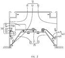
FIG. 2 is a cross sectional view of the flipping installation device for LED strip lighting ofFIG. 1 . - The present application is illustrated by way of example and not by way of limitation in the figures of the accompanying drawings. It should be noted that references to "an" or "one" embodiment in this application are not necessarily to the same embodiment, and such references mean at least one.
- Referring to
FIG. 1 to FIG. 2 , a flipping installation device 100 for LED strip lighting is shown. The flipping installation device 100 for LED strip lighting includes aninstallation frame 10, ahouse 20 receiving in theinstallation frame 10, alink mechanism 30 disposed in one of two jointing edges between theinstallation frame 10 and thehouse 20, and aclamping mechanism 40 disposed in the other of two jointing edges between theinstallation frame 10 and thehouse 20. It may be understood that the LED strip lighting further includes other components, such as cover, end cap, wires, and so on, which is well known for these skilled in the art and not described in detail. - The
installation frame 10 may be embedded into a ceiling and may be a square slot or other shape, such as an arc, a semicircle, or the like. In the present embodiment, theinstallation frame 10 is a square slot and includes a firstfree edge 11 and a secondfree edge 12. Theinstallation frame 10 may be made of metal material for heat dissipation. Two stop bars 13 are respectively provided on the first and secondfree edges house 20 into theinstallation frame 10 when thehouse 20 is rotated into the slot of theinstallation frame 10. - The
house 20 is configured for mounting the cover, light module, or the like, and has a strip-typed structure and has a trapezoidal frame on the cross section perpendicular to an axial direction of thehouse 20. Thehouse 20 includes anupper base 21, a bottom base (not labeled), afirst side wall 22, and asecond side wall 23. Thefirst side wall 22 and thesecond side wall 23 are opposed to each other on both sides of theupper base 21. When the light source module is arranged on theupper base 21, light is emitted from the bottom base of the trapezoid so as to facilitate the diffusion of the light emitted by the light source module, that is, to enlarge the irradiation range of the LED strip lighting. Since thehouse 20 has the trapezoid structure, thelink mechanism 30 and theclamping mechanism 40 can be disposed on the gap between thehouse 20 and theinstallation frame 10 so as to make the whole lamp compact structure and reduce costs. For beauty, the length of the bottom base of thehouse 20 is equal to the distance between the first and secondfree edge installation frame 10. - In one LED strip lighting, it may have one or
more link mechanisms 30. The number of thelink mechanisms 30 in the LED strip lighting are depend primarily on an axial length of the LED strip lamp and an axial length of thelink mechanism 30. In the present embodiment, the axial length of the LED strip lighting is 1.5 meters and the LED strip lighting includes twolink mechanisms 30 which are respectively mounted near two ends of theinstallation frame 10. The twoline mechanisms 30 are disposed in one of two jointing edges which are formed by thefirst side wall 22 and the firstfree edge 11. Each of theline mechanisms 30 includes afirst link 31 disposed on the firstfree edge 11 of theinstallation frame 10, asecond link 32 disposed on theupper base 21 of thehouse 20, athird link 33 rotatably connected between the first andsecond links bearings 34. One of the twobearings 34 is configured for connecting thefirst link 31 and thesecond link 32, the other is used to connect thesecond link 32 and thethird link 33. When thethird link 33 is rotated around thebearing 34, thehouse 20 can be turned over with thethird link 33. In order that the direction of the pulling force, which is applied to thethird link 33, is aligned with the direction of the gravity received by thehouse 20, the first and second andthird links house 20 when thehouse 20 has been installed. Since the first andsecond links installation frame 10 and thehouse 20 and the direction of the pulling force, which is applied to thethird link 33, is aligned with the direction of the gravity received by thehouse 20, the first andsecond links house 20 has been installed. - The number of the clamping
mechanisms 40 coincide with that of thelink mechanism 30, and theclamping mechanism 40 is disposed opposite to thelink mechanism 30. Therefore, in the present embodiment, the LED strip lighting includes two clampingmechanisms 40. The clampingmechanisms 40 are disposed the other jointing edge which is formed by thesecond side wall 23 and the secondfree edge 12. Each of the clampingmechanisms 40 includes a catch head 41 disposed on theinstallation frame 10, and aresilient lock 42 disposed in thehouse 20 and coupled to the catch head 41. One end of the catch head 41 is fixed the secondfree edge 12 of theinstallation frame 10, and the other extends from the secondfree edge 12. One end of theresilient lock 42 is fixed on thehouse 20 and the other is free so as to the free end of theresilient lock 42 have resilience. The free end of theresilient lock 42 has a V-shaped structure and the V-shaped free end thereof abuts against the catch head 41 when thehouse 20 is received into theinstallation frame 10. It can be understood that the structure of theclamping mechanism 40 may be of a variety of styles as long as one side of thehouse 20 can be clamped into theinstallation frame 10 and is easy to be disassembled therefrom. Thelink mechanism 30 and theclamping mechanism 40 are located on the opposite side of thehouse 20. Therefore, when theresilient lock 42 is coupled into the catch head 41, thehouse 20 has been received into theinstallation frame 10, and the first and second andthird links third link 33, is aligned with the direction of the gravity received by thehouse 20, the first, second andthird links third link 33 can be held in its vertical state due to the ejection action of theclamping mechanism 40 to form a stable balance state so as to prevent thehouse 20 from rotating around the twobearings 34. As a result, the positional relationship between the first, second andthird links house 20 can be fixed into theinstallation frame 10 so as to achieve the purpose of completing the installation of thehouse 20 and theinstallation frame 10. - When need to disassemble, one side of the
house 20 in which theclamping mechanism 40 is disposed may be raised by means of a tool, such as straight screwdriver, or the like, so that theresilient lock 42 is disengaged from the catch head 41. And thehouse 20 is turn down around thebear 34 under the action of gravity, thereby removing thehouse 20 from theinstallation frame 10. - As described above, as the flipping installation device 100 for LED strip lighting has the
link mechanism 30 and theclamping mechanism 40, theinstallation frame 10 can be firstly fixed into an installation surface, such as the ceiling, or the like, and then, thehouse 20 is mounted into theinstallation frame 10. Since theinstallation frame 10 can be embedded into the ceiling, thehouse 20 also can be embedded into the ceiling so that the light emitting surface of thehouse 20 can be flush with the ceiling. As a result, the ceiling having the LED strip lighting has larger distance from the ground and more beautiful. - While the disclosure has been described by way of example and in terms of exemplary embodiment, it is to be understood that the disclosure is not limited thereto. To the contrary, it is intended to cover various modifications and similar arrangements (as would be apparent to those skilled in the art). Therefore, the scope of the appended claims should be accorded the broadest interpretation so as to encompass all such modifications and similar arrangements.
Claims (9)
- A flipping installation device for LED strip lighting, comprising:an installation frame (10);a house (20) received in the installation frame;at least one link mechanism (30) disposed in one of two jointing edges of the installation frame (10) and the house (20), each of the at least one link mechanism (30) comprising a first link (31) mounted on the installation frame (10) and being disposed on a first free edge (11) of the installation frame, a second link (32) disposed on an upper base (21) of the house (20), and a third link (33) rotatably connected between the first and second links (31, 32), and two bearings (34) configured for connecting the first link (31) and the second link (32) and connecting the second link (32) and the third link (33), respectively, the first and second and third links (31, 32, 33) being perpendicular to each other in a cross section perpendicular to an axial direction of the house (20) when the house (20) has been installed into the installation frame (10); andat least one clamping mechanism (40) disposed in the other jointing edge of the installation frame (10) and the house (20), each of the at least one clamping mechanism (40) comprising a catch head (41) disposed on the installation frame (10), and a resilient lock (42) disposed on the house (10) and coupled to the catch head (41), the link mechanism (30) and the clamping mechanism (40) being located on the opposite side of the house (20).
- The flipping installation device for LED strip lighting as claimed in claim 1, wherein the installation frame (10) is a square slot.
- The flipping installation device for LED strip lighting as claimed in claim 2, wherein two stop bars (13) are respectively provided on the two free edges of the installation frame (10), the two stop bars (13) are configured for limiting the depth of the house (20) in the installation frame (10) when the house (20) is rotated into the square slot of the installation frame (10).
- The flipping installation device for LED strip lighting as claimed in one of the preceding claims, wherein the house (20) is a strip-typed structure and has a trapezoidal frame on the cross section perpendicular to the axial direction of the house (20).
- The flipping installation device for LED strip lighting as claimed in claim 4, wherein the link mechanism (30) and the clamping mechanism (40) are disposed on the gap between the house (20) and the installation frame (10).
- The flipping installation device for LED strip lighting as claimed in preceding claims, wherein one end of the resilient lock (42) is fixed on the house (20), and the other is a free end.
- The flipping installation device for LED strip lighting as claimed in claim 6, wherein the free end has a V-shaped structure and abuts against the catch head (41) when the house (20) is received into the installation frame (10).
- The flipping installation device for LED strip lighting as claimed in preceding claims, wherein the positional relationship between the first, second and third links (33) in the vertical state is maintained when the house (20) can be fixed into the installation frame (10).
- The flipping installation device for LED strip lighting as claimed in preceding claims, wherein the direction of the pulling force, which is applied to the third link (33), is aligned with the direction of the gravity received by the house (20).
Applications Claiming Priority (1)
| Application Number | Priority Date | Filing Date | Title |
|---|---|---|---|
| CN201610459966.0A CN107529602A (en) | 2016-06-22 | 2016-06-22 | A kind of convertible mounting structure of LED bar graph light fixture |
Publications (2)
| Publication Number | Publication Date |
|---|---|
| EP3260773A1 EP3260773A1 (en) | 2017-12-27 |
| EP3260773B1 true EP3260773B1 (en) | 2019-10-09 |
Family
ID=59091384
Family Applications (1)
| Application Number | Title | Priority Date | Filing Date |
|---|---|---|---|
| EP17176665.2A Active EP3260773B1 (en) | 2016-06-22 | 2017-06-19 | Flipping installation device for led strip lighting |
Country Status (3)
| Country | Link |
|---|---|
| US (1) | US10132479B2 (en) |
| EP (1) | EP3260773B1 (en) |
| CN (1) | CN107529602A (en) |
Citations (1)
| Publication number | Priority date | Publication date | Assignee | Title |
|---|---|---|---|---|
| WO2010094867A1 (en) * | 2009-02-23 | 2010-08-26 | Normalu (Sas) | Light box with spring-loaded scissor-stay opening |
Family Cites Families (17)
| Publication number | Priority date | Publication date | Assignee | Title |
|---|---|---|---|---|
| DE3210589A1 (en) * | 1982-03-23 | 1983-10-06 | Eckart Roth | Frame to be installed in particular in a ceiling or a ceiling substructure and having an openable cover plate |
| US5226719A (en) * | 1992-06-08 | 1993-07-13 | Steelcase Inc. | Quick mounting arrangement for light fixtures in overhead cabinets and the like |
| US6149280A (en) * | 1999-02-05 | 2000-11-21 | Spaulding Lighting, Inc. | Method and apparatus for retrofitting canopy luminaire assemblies |
| WO2004071143A1 (en) * | 2003-02-07 | 2004-08-19 | Matsushita Electric Industrial Co., Ltd. | Socket for led light source and lighting system using the socket |
| WO2008067515A1 (en) * | 2006-11-30 | 2008-06-05 | Cree Led Lighting Solutions, Inc. | Light fixtures, lighting devices, and components for the same |
| US7878668B2 (en) * | 2007-03-20 | 2011-02-01 | Emerge Products, Llc | Deployable emergency lighting system |
| US7500766B1 (en) * | 2007-12-26 | 2009-03-10 | Elaine M Reynolds | Tinted lens assembly for recessed compact fluorescent lights |
| TWM394411U (en) * | 2010-06-11 | 2010-12-11 | Kai Xiang Lighting Equipment Co Ltd | Structure of LED down light module |
| FR2974132B1 (en) * | 2011-04-18 | 2013-06-14 | Normalu | DEVICE FOR TILTING AT LEAST ONE MOBILE HOUSING MOUNTED ON A WALL SUCH AS A WALL OR A CEILING. |
| CN202065835U (en) * | 2011-05-12 | 2011-12-07 | 东莞骏威电子制品有限公司 | LED (light-emitting diode) tube lamp capable of being embedded into ceiling plate |
| CA2765289A1 (en) * | 2012-01-20 | 2013-07-20 | Somboun Chia | Extruded led light heat sink with attached housing |
| US9568172B1 (en) * | 2012-05-03 | 2017-02-14 | Musco Corporation | Apparatus, system, and method for aiming LED modules |
| KR101351359B1 (en) * | 2013-03-04 | 2014-01-14 | 주식회사 린노 | Line type lighting device of reclaiming in ceiling |
| EP2952806A1 (en) * | 2014-06-02 | 2015-12-09 | General Electric Company | Pivoting heat sink for LED luminaire |
| KR101707662B1 (en) * | 2014-07-08 | 2017-02-21 | 주식회사 케이엠더블유 | LED lighting device with camera |
| US9857038B2 (en) * | 2016-04-01 | 2018-01-02 | Ketra, Inc. | Recessed downlight fixture and method for installing and universally adjusting the fixture in a new construction application |
| CN205807326U (en) * | 2016-06-22 | 2016-12-14 | 赛尔富电子有限公司 | A kind of convertible mounting structure of LED bar graph light fixture |
-
2016
- 2016-06-22 CN CN201610459966.0A patent/CN107529602A/en active Pending
-
2017
- 2017-06-19 EP EP17176665.2A patent/EP3260773B1/en active Active
- 2017-06-21 US US15/629,712 patent/US10132479B2/en active Active
Patent Citations (1)
| Publication number | Priority date | Publication date | Assignee | Title |
|---|---|---|---|---|
| WO2010094867A1 (en) * | 2009-02-23 | 2010-08-26 | Normalu (Sas) | Light box with spring-loaded scissor-stay opening |
Also Published As
| Publication number | Publication date |
|---|---|
| US20170370563A1 (en) | 2017-12-28 |
| EP3260773A1 (en) | 2017-12-27 |
| US10132479B2 (en) | 2018-11-20 |
| CN107529602A (en) | 2018-01-02 |
Similar Documents
| Publication | Publication Date | Title |
|---|---|---|
| US9447949B2 (en) | Light fixture | |
| US7914193B2 (en) | LED light fixture | |
| CA2916752C (en) | Lighting device and lens assembly | |
| JP2015509656A (en) | Light Emitting Diode Troffer Door Assembly | |
| CA2906013C (en) | Led architectural luminaire having improved illumination characteristics | |
| CA2570789A1 (en) | Lighting fixture with smooth adjustable beam width | |
| US7946738B2 (en) | Lighting assembly having pivoting lens retaining member | |
| KR101013208B1 (en) | Light emitting diode race way luminaire | |
| KR101520224B1 (en) | Device to mounting transmtting plate holder for lighting | |
| US10168033B2 (en) | Downlight | |
| KR20200040340A (en) | Installation structure of edge type LED light | |
| KR102078681B1 (en) | Rectangular Ceiling Recessed Lights | |
| EP3260773B1 (en) | Flipping installation device for led strip lighting | |
| KR20180043498A (en) | Led lighting device using magnet | |
| CN105202416A (en) | Angle-adjustable track lamp | |
| KR101033942B1 (en) | Apparatus for automatic fastening of ceiling mounted type lamp | |
| KR20120069386A (en) | Led corner lamp | |
| KR101663052B1 (en) | LED ceiling lights | |
| CN215112311U (en) | Lamp set | |
| KR101200809B1 (en) | Led light having radiation function | |
| KR200484656Y1 (en) | Light for lighting apparatus | |
| KR200483006Y1 (en) | Ceiling bar assembly for lighting apparatus | |
| AU2011101089A4 (en) | Downlight Fixture | |
| TWI403665B (en) | Separate downlight structure | |
| KR20090008910U (en) | Fluorescent Lamp Implement |
Legal Events
| Date | Code | Title | Description |
|---|---|---|---|
| PUAI | Public reference made under article 153(3) epc to a published international application that has entered the european phase |
Free format text: ORIGINAL CODE: 0009012 |
|
| STAA | Information on the status of an ep patent application or granted ep patent |
Free format text: STATUS: THE APPLICATION HAS BEEN PUBLISHED |
|
| AK | Designated contracting states |
Kind code of ref document: A1 Designated state(s): AL AT BE BG CH CY CZ DE DK EE ES FI FR GB GR HR HU IE IS IT LI LT LU LV MC MK MT NL NO PL PT RO RS SE SI SK SM TR |
|
| AX | Request for extension of the european patent |
Extension state: BA ME |
|
| STAA | Information on the status of an ep patent application or granted ep patent |
Free format text: STATUS: REQUEST FOR EXAMINATION WAS MADE |
|
| 17P | Request for examination filed |
Effective date: 20180620 |
|
| RBV | Designated contracting states (corrected) |
Designated state(s): AL AT BE BG CH CY CZ DE DK EE ES FI FR GB GR HR HU IE IS IT LI LT LU LV MC MK MT NL NO PL PT RO RS SE SI SK SM TR |
|
| STAA | Information on the status of an ep patent application or granted ep patent |
Free format text: STATUS: EXAMINATION IS IN PROGRESS |
|
| 17Q | First examination report despatched |
Effective date: 20180914 |
|
| RIC1 | Information provided on ipc code assigned before grant |
Ipc: F21S 8/02 20060101ALI20190327BHEP Ipc: F21V 17/16 20060101ALI20190327BHEP Ipc: F21Y 103/10 20160101ALN20190327BHEP Ipc: F21Y 115/10 20160101ALN20190327BHEP Ipc: F21V 21/088 20060101AFI20190327BHEP Ipc: F21V 21/04 20060101ALI20190327BHEP Ipc: F21V 21/02 20060101ALI20190327BHEP |
|
| GRAP | Despatch of communication of intention to grant a patent |
Free format text: ORIGINAL CODE: EPIDOSNIGR1 |
|
| STAA | Information on the status of an ep patent application or granted ep patent |
Free format text: STATUS: GRANT OF PATENT IS INTENDED |
|
| RIC1 | Information provided on ipc code assigned before grant |
Ipc: F21Y 115/10 20160101ALN20190426BHEP Ipc: F21Y 103/10 20160101ALN20190426BHEP Ipc: F21V 21/04 20060101ALI20190426BHEP Ipc: F21V 21/088 20060101AFI20190426BHEP Ipc: F21S 8/02 20060101ALI20190426BHEP Ipc: F21V 21/02 20060101ALI20190426BHEP Ipc: F21V 17/16 20060101ALI20190426BHEP |
|
| INTG | Intention to grant announced |
Effective date: 20190516 |
|
| RIN1 | Information on inventor provided before grant (corrected) |
Inventor name: WU, XUFENG Inventor name: LIN, WANJIONG |
|
| GRAS | Grant fee paid |
Free format text: ORIGINAL CODE: EPIDOSNIGR3 |
|
| GRAA | (expected) grant |
Free format text: ORIGINAL CODE: 0009210 |
|
| STAA | Information on the status of an ep patent application or granted ep patent |
Free format text: STATUS: THE PATENT HAS BEEN GRANTED |
|
| AK | Designated contracting states |
Kind code of ref document: B1 Designated state(s): AL AT BE BG CH CY CZ DE DK EE ES FI FR GB GR HR HU IE IS IT LI LT LU LV MC MK MT NL NO PL PT RO RS SE SI SK SM TR |
|
| REG | Reference to a national code |
Ref country code: GB Ref legal event code: FG4D |
|
| REG | Reference to a national code |
Ref country code: CH Ref legal event code: EP |
|
| REG | Reference to a national code |
Ref country code: IE Ref legal event code: FG4D |
|
| REG | Reference to a national code |
Ref country code: DE Ref legal event code: R096 Ref document number: 602017007574 Country of ref document: DE |
|
| REG | Reference to a national code |
Ref country code: AT Ref legal event code: REF Ref document number: 1189262 Country of ref document: AT Kind code of ref document: T Effective date: 20191115 |
|
| REG | Reference to a national code |
Ref country code: NL Ref legal event code: MP Effective date: 20191009 |
|
| REG | Reference to a national code |
Ref country code: LT Ref legal event code: MG4D |
|
| REG | Reference to a national code |
Ref country code: AT Ref legal event code: MK05 Ref document number: 1189262 Country of ref document: AT Kind code of ref document: T Effective date: 20191009 |
|
| PG25 | Lapsed in a contracting state [announced via postgrant information from national office to epo] |
Ref country code: AT Free format text: LAPSE BECAUSE OF FAILURE TO SUBMIT A TRANSLATION OF THE DESCRIPTION OR TO PAY THE FEE WITHIN THE PRESCRIBED TIME-LIMIT Effective date: 20191009 Ref country code: NL Free format text: LAPSE BECAUSE OF FAILURE TO SUBMIT A TRANSLATION OF THE DESCRIPTION OR TO PAY THE FEE WITHIN THE PRESCRIBED TIME-LIMIT Effective date: 20191009 Ref country code: LV Free format text: LAPSE BECAUSE OF FAILURE TO SUBMIT A TRANSLATION OF THE DESCRIPTION OR TO PAY THE FEE WITHIN THE PRESCRIBED TIME-LIMIT Effective date: 20191009 Ref country code: SE Free format text: LAPSE BECAUSE OF FAILURE TO SUBMIT A TRANSLATION OF THE DESCRIPTION OR TO PAY THE FEE WITHIN THE PRESCRIBED TIME-LIMIT Effective date: 20191009 Ref country code: PL Free format text: LAPSE BECAUSE OF FAILURE TO SUBMIT A TRANSLATION OF THE DESCRIPTION OR TO PAY THE FEE WITHIN THE PRESCRIBED TIME-LIMIT Effective date: 20191009 Ref country code: NO Free format text: LAPSE BECAUSE OF FAILURE TO SUBMIT A TRANSLATION OF THE DESCRIPTION OR TO PAY THE FEE WITHIN THE PRESCRIBED TIME-LIMIT Effective date: 20200109 Ref country code: FI Free format text: LAPSE BECAUSE OF FAILURE TO SUBMIT A TRANSLATION OF THE DESCRIPTION OR TO PAY THE FEE WITHIN THE PRESCRIBED TIME-LIMIT Effective date: 20191009 Ref country code: BG Free format text: LAPSE BECAUSE OF FAILURE TO SUBMIT A TRANSLATION OF THE DESCRIPTION OR TO PAY THE FEE WITHIN THE PRESCRIBED TIME-LIMIT Effective date: 20200109 Ref country code: GR Free format text: LAPSE BECAUSE OF FAILURE TO SUBMIT A TRANSLATION OF THE DESCRIPTION OR TO PAY THE FEE WITHIN THE PRESCRIBED TIME-LIMIT Effective date: 20200110 Ref country code: ES Free format text: LAPSE BECAUSE OF FAILURE TO SUBMIT A TRANSLATION OF THE DESCRIPTION OR TO PAY THE FEE WITHIN THE PRESCRIBED TIME-LIMIT Effective date: 20191009 Ref country code: LT Free format text: LAPSE BECAUSE OF FAILURE TO SUBMIT A TRANSLATION OF THE DESCRIPTION OR TO PAY THE FEE WITHIN THE PRESCRIBED TIME-LIMIT Effective date: 20191009 Ref country code: PT Free format text: LAPSE BECAUSE OF FAILURE TO SUBMIT A TRANSLATION OF THE DESCRIPTION OR TO PAY THE FEE WITHIN THE PRESCRIBED TIME-LIMIT Effective date: 20200210 |
|
| PG25 | Lapsed in a contracting state [announced via postgrant information from national office to epo] |
Ref country code: HR Free format text: LAPSE BECAUSE OF FAILURE TO SUBMIT A TRANSLATION OF THE DESCRIPTION OR TO PAY THE FEE WITHIN THE PRESCRIBED TIME-LIMIT Effective date: 20191009 Ref country code: IS Free format text: LAPSE BECAUSE OF FAILURE TO SUBMIT A TRANSLATION OF THE DESCRIPTION OR TO PAY THE FEE WITHIN THE PRESCRIBED TIME-LIMIT Effective date: 20200224 Ref country code: RS Free format text: LAPSE BECAUSE OF FAILURE TO SUBMIT A TRANSLATION OF THE DESCRIPTION OR TO PAY THE FEE WITHIN THE PRESCRIBED TIME-LIMIT Effective date: 20191009 |
|
| PG25 | Lapsed in a contracting state [announced via postgrant information from national office to epo] |
Ref country code: AL Free format text: LAPSE BECAUSE OF FAILURE TO SUBMIT A TRANSLATION OF THE DESCRIPTION OR TO PAY THE FEE WITHIN THE PRESCRIBED TIME-LIMIT Effective date: 20191009 |
|
| REG | Reference to a national code |
Ref country code: DE Ref legal event code: R097 Ref document number: 602017007574 Country of ref document: DE |
|
| PG2D | Information on lapse in contracting state deleted |
Ref country code: IS |
|
| PG25 | Lapsed in a contracting state [announced via postgrant information from national office to epo] |
Ref country code: CZ Free format text: LAPSE BECAUSE OF FAILURE TO SUBMIT A TRANSLATION OF THE DESCRIPTION OR TO PAY THE FEE WITHIN THE PRESCRIBED TIME-LIMIT Effective date: 20191009 Ref country code: RO Free format text: LAPSE BECAUSE OF FAILURE TO SUBMIT A TRANSLATION OF THE DESCRIPTION OR TO PAY THE FEE WITHIN THE PRESCRIBED TIME-LIMIT Effective date: 20191009 Ref country code: EE Free format text: LAPSE BECAUSE OF FAILURE TO SUBMIT A TRANSLATION OF THE DESCRIPTION OR TO PAY THE FEE WITHIN THE PRESCRIBED TIME-LIMIT Effective date: 20191009 Ref country code: DK Free format text: LAPSE BECAUSE OF FAILURE TO SUBMIT A TRANSLATION OF THE DESCRIPTION OR TO PAY THE FEE WITHIN THE PRESCRIBED TIME-LIMIT Effective date: 20191009 Ref country code: IS Free format text: LAPSE BECAUSE OF FAILURE TO SUBMIT A TRANSLATION OF THE DESCRIPTION OR TO PAY THE FEE WITHIN THE PRESCRIBED TIME-LIMIT Effective date: 20200209 |
|
| PLBE | No opposition filed within time limit |
Free format text: ORIGINAL CODE: 0009261 |
|
| STAA | Information on the status of an ep patent application or granted ep patent |
Free format text: STATUS: NO OPPOSITION FILED WITHIN TIME LIMIT |
|
| PG25 | Lapsed in a contracting state [announced via postgrant information from national office to epo] |
Ref country code: IT Free format text: LAPSE BECAUSE OF FAILURE TO SUBMIT A TRANSLATION OF THE DESCRIPTION OR TO PAY THE FEE WITHIN THE PRESCRIBED TIME-LIMIT Effective date: 20191009 Ref country code: SM Free format text: LAPSE BECAUSE OF FAILURE TO SUBMIT A TRANSLATION OF THE DESCRIPTION OR TO PAY THE FEE WITHIN THE PRESCRIBED TIME-LIMIT Effective date: 20191009 Ref country code: SK Free format text: LAPSE BECAUSE OF FAILURE TO SUBMIT A TRANSLATION OF THE DESCRIPTION OR TO PAY THE FEE WITHIN THE PRESCRIBED TIME-LIMIT Effective date: 20191009 |
|
| 26N | No opposition filed |
Effective date: 20200710 |
|
| PG25 | Lapsed in a contracting state [announced via postgrant information from national office to epo] |
Ref country code: SI Free format text: LAPSE BECAUSE OF FAILURE TO SUBMIT A TRANSLATION OF THE DESCRIPTION OR TO PAY THE FEE WITHIN THE PRESCRIBED TIME-LIMIT Effective date: 20191009 |
|
| PG25 | Lapsed in a contracting state [announced via postgrant information from national office to epo] |
Ref country code: MC Free format text: LAPSE BECAUSE OF FAILURE TO SUBMIT A TRANSLATION OF THE DESCRIPTION OR TO PAY THE FEE WITHIN THE PRESCRIBED TIME-LIMIT Effective date: 20191009 |
|
| REG | Reference to a national code |
Ref country code: CH Ref legal event code: PL |
|
| PG25 | Lapsed in a contracting state [announced via postgrant information from national office to epo] |
Ref country code: LU Free format text: LAPSE BECAUSE OF NON-PAYMENT OF DUE FEES Effective date: 20200619 |
|
| REG | Reference to a national code |
Ref country code: BE Ref legal event code: MM Effective date: 20200630 |
|
| PG25 | Lapsed in a contracting state [announced via postgrant information from national office to epo] |
Ref country code: FR Free format text: LAPSE BECAUSE OF NON-PAYMENT OF DUE FEES Effective date: 20200630 Ref country code: CH Free format text: LAPSE BECAUSE OF NON-PAYMENT OF DUE FEES Effective date: 20200630 Ref country code: LI Free format text: LAPSE BECAUSE OF NON-PAYMENT OF DUE FEES Effective date: 20200630 Ref country code: IE Free format text: LAPSE BECAUSE OF NON-PAYMENT OF DUE FEES Effective date: 20200619 |
|
| PG25 | Lapsed in a contracting state [announced via postgrant information from national office to epo] |
Ref country code: BE Free format text: LAPSE BECAUSE OF NON-PAYMENT OF DUE FEES Effective date: 20200630 |
|
| PG25 | Lapsed in a contracting state [announced via postgrant information from national office to epo] |
Ref country code: TR Free format text: LAPSE BECAUSE OF FAILURE TO SUBMIT A TRANSLATION OF THE DESCRIPTION OR TO PAY THE FEE WITHIN THE PRESCRIBED TIME-LIMIT Effective date: 20191009 Ref country code: MT Free format text: LAPSE BECAUSE OF FAILURE TO SUBMIT A TRANSLATION OF THE DESCRIPTION OR TO PAY THE FEE WITHIN THE PRESCRIBED TIME-LIMIT Effective date: 20191009 Ref country code: CY Free format text: LAPSE BECAUSE OF FAILURE TO SUBMIT A TRANSLATION OF THE DESCRIPTION OR TO PAY THE FEE WITHIN THE PRESCRIBED TIME-LIMIT Effective date: 20191009 |
|
| PG25 | Lapsed in a contracting state [announced via postgrant information from national office to epo] |
Ref country code: MK Free format text: LAPSE BECAUSE OF FAILURE TO SUBMIT A TRANSLATION OF THE DESCRIPTION OR TO PAY THE FEE WITHIN THE PRESCRIBED TIME-LIMIT Effective date: 20191009 |
|
| PGFP | Annual fee paid to national office [announced via postgrant information from national office to epo] |
Ref country code: DE Payment date: 20230630 Year of fee payment: 7 |
|
| PGFP | Annual fee paid to national office [announced via postgrant information from national office to epo] |
Ref country code: GB Payment date: 20230623 Year of fee payment: 7 |