US6149280A - Method and apparatus for retrofitting canopy luminaire assemblies - Google Patents
Method and apparatus for retrofitting canopy luminaire assemblies Download PDFInfo
- Publication number
- US6149280A US6149280A US09/245,375 US24537599A US6149280A US 6149280 A US6149280 A US 6149280A US 24537599 A US24537599 A US 24537599A US 6149280 A US6149280 A US 6149280A
- Authority
- US
- United States
- Prior art keywords
- housing
- deck
- assembly
- canopy
- bracket
- Prior art date
- Legal status (The legal status is an assumption and is not a legal conclusion. Google has not performed a legal analysis and makes no representation as to the accuracy of the status listed.)
- Expired - Fee Related
Links
- 238000000034 method Methods 0.000 title claims abstract description 33
- 230000000712 assembly Effects 0.000 title abstract description 9
- 238000000429 assembly Methods 0.000 title abstract description 9
- 238000009420 retrofitting Methods 0.000 title abstract description 5
- 238000010586 diagram Methods 0.000 description 8
- 239000000463 material Substances 0.000 description 8
- 230000007246 mechanism Effects 0.000 description 7
- 239000004033 plastic Substances 0.000 description 7
- 229910052751 metal Inorganic materials 0.000 description 5
- 239000002184 metal Substances 0.000 description 5
- 238000003466 welding Methods 0.000 description 5
- 239000000853 adhesive Substances 0.000 description 4
- 230000001070 adhesive effect Effects 0.000 description 4
- 239000003990 capacitor Substances 0.000 description 4
- -1 for example Substances 0.000 description 4
- 239000007858 starting material Substances 0.000 description 4
- 239000003562 lightweight material Substances 0.000 description 3
- 239000006260 foam Substances 0.000 description 2
- 239000005060 rubber Substances 0.000 description 2
- 229910052782 aluminium Inorganic materials 0.000 description 1
- XAGFODPZIPBFFR-UHFFFAOYSA-N aluminium Chemical compound [Al] XAGFODPZIPBFFR-UHFFFAOYSA-N 0.000 description 1
- 239000011521 glass Substances 0.000 description 1
- 239000003292 glue Substances 0.000 description 1
- 238000009434 installation Methods 0.000 description 1
- 239000007788 liquid Substances 0.000 description 1
- 238000012986 modification Methods 0.000 description 1
- 230000004048 modification Effects 0.000 description 1
- 230000008569 process Effects 0.000 description 1
- 238000007634 remodeling Methods 0.000 description 1
- 230000008439 repair process Effects 0.000 description 1
- 238000007789 sealing Methods 0.000 description 1
- 239000003566 sealing material Substances 0.000 description 1
- 229910001220 stainless steel Inorganic materials 0.000 description 1
- 239000010935 stainless steel Substances 0.000 description 1
- 239000011800 void material Substances 0.000 description 1
Images


Classifications
-
- F—MECHANICAL ENGINEERING; LIGHTING; HEATING; WEAPONS; BLASTING
- F21—LIGHTING
- F21S—NON-PORTABLE LIGHTING DEVICES; SYSTEMS THEREOF; VEHICLE LIGHTING DEVICES SPECIALLY ADAPTED FOR VEHICLE EXTERIORS
- F21S8/00—Lighting devices intended for fixed installation
- F21S8/02—Lighting devices intended for fixed installation of recess-mounted type, e.g. downlighters
- F21S8/026—Lighting devices intended for fixed installation of recess-mounted type, e.g. downlighters intended to be recessed in a ceiling or like overhead structure, e.g. suspended ceiling
-
- F—MECHANICAL ENGINEERING; LIGHTING; HEATING; WEAPONS; BLASTING
- F21—LIGHTING
- F21V—FUNCTIONAL FEATURES OR DETAILS OF LIGHTING DEVICES OR SYSTEMS THEREOF; STRUCTURAL COMBINATIONS OF LIGHTING DEVICES WITH OTHER ARTICLES, NOT OTHERWISE PROVIDED FOR
- F21V17/00—Fastening of component parts of lighting devices, e.g. shades, globes, refractors, reflectors, filters, screens, grids or protective cages
- F21V17/10—Fastening of component parts of lighting devices, e.g. shades, globes, refractors, reflectors, filters, screens, grids or protective cages characterised by specific fastening means or way of fastening
- F21V17/107—Fastening of component parts of lighting devices, e.g. shades, globes, refractors, reflectors, filters, screens, grids or protective cages characterised by specific fastening means or way of fastening using hinge joints
-
- F—MECHANICAL ENGINEERING; LIGHTING; HEATING; WEAPONS; BLASTING
- F21—LIGHTING
- F21V—FUNCTIONAL FEATURES OR DETAILS OF LIGHTING DEVICES OR SYSTEMS THEREOF; STRUCTURAL COMBINATIONS OF LIGHTING DEVICES WITH OTHER ARTICLES, NOT OTHERWISE PROVIDED FOR
- F21V21/00—Supporting, suspending, or attaching arrangements for lighting devices; Hand grips
- F21V21/02—Wall, ceiling, or floor bases; Fixing pendants or arms to the bases
- F21V21/04—Recessed bases
Definitions
- the present invention relates to the field of securing canopy luminaries, and more particularly to securing canopy luminaries in place of existing fixtures.
- Canopy luminaire assemblies are used in many areas, such as for gas stations, restaurant drive-through windows, and other areas where over-head lighting is desirable.
- Canopy luminaire assemblies generally comprise relatively high power light sources to distribute a large amount of light to outdoor areas.
- these fixtures generally comprise electrical components, including a ballast and a light source connected to the ballast.
- the ballast and light source are generally housed in a single housing that is then affixed to the canopy.
- Many of these canopy luminaires dispose the housing above the canopy and then cut a large hole in the canopy through which the light may project.
- These luminaires may be referred to as recessed box type luminaires.
- a lens structure may then be disposed on the underside of the canopy.
- patching requires additional labor costs because it involves the use of saws, drills, and other precision tools to fit a new fixture into a void left by the removal of an old fixture. More than one person is required to perform modifications, and the use of general tools is also necessary.
- an object of the present invention is to overcome these and other drawbacks in existing devices.
- Another object of the present invention is to provide a convenient method for installing differently-designed canopy luminaire assemblies using existing luminaire structures.
- Another object of the present invention is to allow the lens structure of canopy luminaire assemblies to be replaced in a convenient and inexpensive manner.
- Another object of the present invention is to provide a device that may replace only part of an existing canopy luminaire yet have exposed portions with the look and feel of a luminaire with a different design from the existing canopy luminaire.
- Another object of the present invention is to provide a system for using the housing and ballast from an existing canopy luminaire with the exposed, exterior components that match another canopy luminaire.
- Another object of the present invention is to provide a system for installing a canopy luminaire structure in place of an existing luminaire with minimal use of tools.
- a method for installing a canopy luminaire in place of an existing lighting structure comprises the steps of removing the existing lens structure and electrical components, securing a deck structure to the housing, such that the deck structure is located substantially outside the housing, and securing an assembly structure to the deck structure.
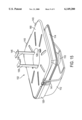
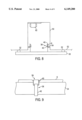
- FIG. 1 depicts a cut-away front view of a retrofit luminaire assembly according to an embodiment of the present invention.
- FIG. 2 depicts a cut-away side view of a retrofit canopy luminaire assembly according to an embodiment of the present invention.
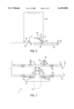
- FIG. 3 depicts a cut-away front view of an existing luminaire assembly housing and housing brackets and a partial view of an adapter plate according to an embodiment of the present invention.
- FIG. 4 depicts a cut-away side view of an existing luminaire assembly housing and housing brackets according to an embodiment of the present invention.
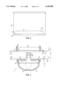
- FIG. 5 depicts a schematic diagram of a canopy luminaire assembly to be retrofitted according to an embodiment of the present invention.
- FIG. 6 depicts a schematic diagram of a housing bracket installed on a housing flange according to an embodiment of the present invention.
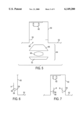
- FIG. 7 depicts a schematic diagram of a housing with housing brackets installed according to an embodiment of the present invention.
- FIG. 8 depicts a schematic diagram of a housing with a deck structure attached to the housing brackets according to an embodiment of the present invention.
- FIG. 9 depicts a schematic diagram of a link of a latch attached to latch teeth of a housing bracket according to an embodiment of the present invention.
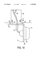
- FIG. 10 depicts a schematic diagram of a retrofit canopy luminaire assembly with an assembly structure pivoted from a deck structure to allow electrical connection of lighting structure according to an embodiment of the present invention.
- FIG. 11 depicts a schematic diagram of a side view of a deck structure secured to housing flanges by a spring clip according to one embodiment of the invention.
- FIG. 12 depicts a schematic diagram of an isometric view of a deck structure and spring clip arrangement for connecting the deck structure to housing flanges according to an embodiment of the invention.
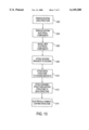
- FIG. 13 depicts a method of assembling a retrofit canopy luminaire assembly according to an embodiment of the present invention.
- FIG. 14 depicts an expanded view of a canopy luminaire assembly the exposed portion of which may resemble the retrofit canopy luminaire assembly of an embodiment of the present invention.
- FIG. 15 depicts a partial cut-away view of the canopy luminaire assembly of FIG. 14.
- the present invention provides a method of installing a retrofit luminaire assembly in place of an existing canopy luminaire assembly.
- An existing box canopy luminaire may comprise a housing 50 located atop a deck canopy 52.
- Existing box canopy luminaires may comprise the CIVIC-DPL sold by Spaulding Lighting Corporation, for example.
- Housing 50 may have housing flanges 54 connected thereto. Housing flanges 54 may also be installed according to the present invention or may not be connected to the housing but only to the canopy itself.
- Electrical components 62 may be located within housing 50, and may further comprise a ballast, a capacitor, and a starter. Electrical components 62 may also comprise other or fewer devices.
- Lens structure 64 which may comprise a reflector 66, a lamp 68, and a lens assembly 70, may be located within deck canopy aperture 60.
- the process of retrofitting an existing canopy luminaire may comprise first removing lens structure 64.
- retrofitting may also comprise removing electrical components 62.
- electrical components 62 may be left in housing 50.
- a retrofit luminaire assembly 1 may be connected to housing 50 and deck canopy 52 upon removing components of an existing recess box canopy luminaire.
- a retrofit luminaire assembly kit may be provided that comprises a retrofit luminaire assembly 1 and a mechanism that secures retrofit luminaire assembly 1 to housing 50 to fit snugly against the underside of a deck canopy 52.
- Retrofit luminaire assembly 1 may comprise a lighting structure 2, an assembly structure 4, and a deck structure 6. Assembly structure 4 and deck structure 6 may be collectively referred to as adapter structure 7.
- Lighting structure 2 may be attached to assembly structure 4 and may be electrically connected to electrical components 62.
- the securement mechanism may comprise a housing bracket 8 that may be secured to housing flanges 54 of housing 50.
- housing brackets 8 may be attached to housing flanges 54 located on housing 50.
- Deck structure 6 may be attached to housing brackets 8 by latch 38.
- the securement mechanism may comprise a spring clip 37 to secure retrofit luminaire assembly 1 to housing flanges 54.
- spring clip 37 may be used to secure deck structure 6 to housing flange 54.
- Assembly structure 4 and deck structure 6 may be pivotally attached by a hinge 28.
- FIGS. 1 and 2 depict a cut-away front and a cut-away side view of a retrofit luminaire assembly 1 according to an embodiment of the present invention.
- Lighting structure 2 may comprise a light source 10 which may be connected to a socket 18 within a socket housing 19. Socket 18 in socket housing 19 may be connected to reflector 14. Socket housing 19 may be attached to assembly fixture 26.
- Lens 12 surrounds and protects light source 10.
- a lighting structure 2 may include a reflector 14, used to direct the light, which may be joined to base pan 16 by reflector fasteners 22.
- a bezel 20 may be placed over and snap onto lens 12.
- base pan 16 may be made of a material of sufficient strength to support lens 12 and reflector 14, such as, for example, metal, plastic, or other such material.
- Base pan 16 may also be molded or die-cast.
- lens 12 may be made from a translucent material, such as, for example, glass, plastic or similar material.
- Socket housing 19 may be comprised of metal, such as stainless steel, aluminum, or other such material.
- Assembly structure 4 may comprise an assembly fixture 26 having an assembly aperture 27.
- Assembly fixture 26 may comprise a plate-like structure. Other shapes, sizes, and arrangements of assembly fixture 26 may also be used.
- Assembly fixture 26 may be made of a light-weight material, such as, for example, plastic, metal, or the like. Other materials may also be used.
- Deck structure 6 may comprise a deck fixture 30 having a deck fixture aperture 31, latch brackets 34 attached to deck fixture 30, and latches 38 attached to latch brackets 34.
- deck fixture 26 may be a plate-like structure. Other shapes, sizes and arrangements of deck fixture 30 may also be used.
- latch brackets 34 may be attached to the upper portion of deck fixture 30.
- Latch brackets 34 may be a variety of shapes.
- latch brackets 34 may be formed in the shape of an "L", as best illustrated in FIG. 1, and attached to deck fixture 30 by latch bracket fastener 36.
- Latch brackets 34 may also be attached by welding, adhesives, or other attachment methods.
- Latch brackets 34 may be made of metal, plastic, or other light weight material.
- latch bracket 34 may comprise an integral part of deck fixture 30, where a portion is turned up (bent), thereby allowing latch 38 to be attached.
- Other structures may also be used.
- Latch 38 may be attached to latch bracket 34 to allow attachment of deck fixture 30 to housing 50.
- Latch 38 may be a toggle latch comprising a link 40 and a clamp 42.
- Latch 38 may be attached to latch bracket 34 by latch fasteners 44, as depicted in FIG. 2.
- Latch 38 may also be attached in other manners, such as by welding, adhesives, or other known methods of attachment.
- a gasket 32 may be attached to the upper portion of deck fixture 30, so as to be interposed between canopy 52 and deck fixture 30.
- gasket 32 may be rectangular and may surround canopy aperture 60.
- Gasket 32 may be made of rubber, foam, plastic, felt, or other suitable seating material to prevent liquid from seeping into the lighting components in lighting structure 2. The function of gasket 32 will be further described below.
- Deck fixture 30 may be made of a light-weight material, such as, for example, plastic, metal, or the like. Other materials may also be used.
- Lighting structure 2 may be attached to assembly structure 4 by assembly fasteners 24.
- Reflector 14 and socket housing 19 of lighting structure 2 may be inserted through assembly plate aperture 27.
- Assembly fasteners 24 may be provided to attach base pan 16 to assembly fixture 26, thereby connecting lighting structure 2 to assembly structure 4.
- reflector fasteners 22 may be used to attach reflector 14 to base pan 16, and to attach base pan 16 to assembly fixture 26, thereby further connecting lighting structure 2 to assembly structure 4.
- Base pan fasteners 24 and reflector fasteners 22 may both be used to attach lighting structure 2 to assembly structure 4.
- a gasket (not shown) may also be placed between base pan 16 and assembly fixture 26 to seal the area around assembly aperture 27. Other attachment methods may also be used.
- FIGS. 3 and 4 illustrate an expanded view of a retrofitted canopy luminaire assembly according to one embodiment of the present invention, and more specifically a view of a deck structure 6 being connected to the housing 50 of a retrofit canopy luminaire assembly.
- Housing 50 may be located above deck canopy 52.
- Housing brackets 8 may be attached to housing flanges 54.
- housing bracket 8 may have two bracket flanges 58 which are substantially parallel to each other, as illustrated in FIGS. 6 and 7. Bracket flanges 58 may be inserted onto housing flange 54 to support housing brackets 8.
- Other methods of attaching housing bracket 8 to housing flange 54 or housing 50 may also be used.
- other methods of attaching housing flanges 54 to housing 50 may also be used.
- housing brackets 8 may be affixed to housing 50 in another manner.
- deck structure 6 and assembly structure 4 may be attached together.
- One attachment device may be a hinge 28. Hinge 28 enables assembly structure 4 to be pivoted relative to deck structure 6 as illustrated in FIG. 10.
- Housing 50 may be accessible through deck fixture aperture 31 due to the relative movement of assembly structure 4 to deck structure 6. Access to housing 50 may allow lighting structure 2 to be electrically connected by wiring 72 to electrical components 62 in housing 50, as illustrated in FIG. 10.
- an improved method of installing a retrofit canopy luminaire assembly is provided, because a single person may install and electrically connect the entire retrofit assembly. Also, because one person may easily access the inside of the canopy luminaire assembly, further service, including repairs and replacements, is also easier.
- Captive screws 25, located opposite of hinge 28, may be secured to cage nuts 29 to secure assembly structure 4 to deck fixture 6 in an upright position.
- Other fasteners which may include screws, bolts, or other types of fasteners, may be used.
- Other methods of securing deck structure 6 to assembly structure 4 may also be used.
- deck structure 6 and assembly structure 4 may be attached by non-pivotable mechanism.
- Non-pivotable mechanisms may include fasteners, welding, adhesives, or other attachment methods.
- Deck structure 6 and assembly structure 4 may also comprise a single structure, referred to as an adapter structure.
- Latch brackets 34 may be attached to the upper portion of an adapter structure, while light structure 2 may be attached to the lower portion of the adapter structure.
- Adapter structure functions similar to the functions of assembly structure 4 and deck structure 6. Other types of deck and assembly structures may also be used.
- deck structure 6 may be positioned below deck canopy 52.
- housing 50 and deck canopy aperture 60 may be aligned.
- Latch brackets 34 may also be aligned with deck canopy aperture 60.
- Deck structure 6 may be raised, thereby inserting latch brackets 34 through deck canopy aperture 60 and into housing 50, as illustrated in FIGS. 3 and 8.
- housing bracket 8 may have latch teeth 56.
- link 40 of latch 38 may be placed in latch teeth 56.
- Clamp 42 may then be pushed into a locking position, such as downward in this embodiment, such that link 40 locks onto latch teeth 56 and supports retrofit canopy luminaire assembly 1.
- Other methods of attaching a retrofit luminaire assembly 1 to a housing may be used.
- pushing clamp 42 of latch 38 into locking position raises deck fixture 30 so as to be substantially flush with deck canopy 52.
- Gasket 32 interposed between deck fixture 30 and deck canopy 52, seals the inner portion of the retrofit luminaire assembly 1.
- latch 38 to lock onto latch teeth 56 allows a tool-less manner for attaching the retrofit canopy luminaire assembly 1 to housing 50. Installation of a retrofit canopy luminaire assembly may be performed more easily, as tools are not necessary, thereby enabling one person to install and electrically connected the retrofitted assembly.
- FIGS. 11 and 12 illustrate another embodiment of the present invention for securing retrofit luminaire assembly 1 to housing 50.
- a portion of deck fixture 30 may include a perpendicular portion 33 and a parallel portion 35.
- spring clip 37 may be attached to parallel portion 35 with a pivot 39.
- Deck fixture 30 may be configured such that perpendicular portion 33 and parallel portion 35 may be inserted through deck canopy aperture 60.
- Parallel portion 35 may be positioned to be substantially flush with housing flange 54.
- Spring clip 37 rotates on pivot 39 to secure parallel portion 35 and housing flange 54.
- Spring clip 37 may have a spring clip tab 41 with which to rotate spring clip 37 about pivot 39, thereby allowing attachment of housing flange 54 and parallel portion 35 without the use of tools.
- Deck fixture 30 may thereby be secured to housing flange 54, and thereby securing retrofit luminaire assembly 1 to housing 50. Other methods for securing retrofit luminaire assembly 1 to housing 50 may also be used.
- existing lens structure 64 may be removed at step 202.
- the existing electrical components 62 may then be removed at step 204.
- Electrical devices 62 may comprise a ballast, a starter, a capacitor, and/or other electrical components.
- the step of installing new electrical components 62 may occur at step 206, including a new ballast, for example.
- existing electrical components 62 may be left in the canopy luminaire assembly.
- Housing brackets 8 may be attached to housing flanges 54 located in a housing 50 at step 208. In another embodiment of the invention, housing brackets 8 may be directly attached to housing 50. The manner for attachment may comprise fasteners (i.e. rivets, bolts, screws, etc.), adhesives, welding, or other mechanisms.
- Deck structure 6 may be attached to housing brackets 8 at step 210.
- One embodiment of the present invention contemplates use of latch 38 to attach deck structure 6 to housing bracket 8.
- Deck structure 6 may have a latch bracket 34 upon which latch 38 may be mounted. Other mechanisms for attaching deck structure 6 may also be used.
- steps 208 and 210 may be replaced with a single step of securing the deck assembly to the housing 50 using spring clips 37.
- Assembly structure 6 may be attached to deck structure 8 at step 212.
- assembly structure 6 and deck structure 4 may be pivotally attached by hinge 28.
- Non-pivotable attachment, such as fasteners, may also be used.
- Lighting structure 2 may be electrically connected at step 214 with the assembly structure 8 pivoted open. According to an embodiment of the present invention, lighting structure 2 may be preassembled to assembly structure 4, before assembly structure 4 is secured to deck structure 6.
- the method of installing a retrofit canopy luminaire assembly may also occur in a different order. For example, it may be desirable to attach deck structure 6 to assembly structure 4 before attaching deck structure 6 to housing brackets 8. Other orders of steps of installing a retrofit canopy luminaire may also be used.
- FIG. 14 illustrates an expanded side view of a canopy luminaire 101 the exposed portion of which the present invention may resemble
- FIG. 15 illustrates a partial cut away view of the same canopy luminaire assembly.
- a detailed description of this luminaire may be provided in U.S. patent application Ser. No. 09/089,214 and U.S. Design Pat. No. 405,207, which are incorporated by reference.
- Like terms in the retrofit canopy luminaire assembly will generally correspond to like terms in the canopy luminaire assembly of FIGS. 14 and 15.
- the canopy luminaire assembly 101 comprises a lower portion 102 and a ballast section 103.
- the lower portion 102 may include a lens 112 and a reflector 114.
- Reflector 114 may be attached to a base pan 116 by fasteners 122.
- Lens 112 may be attached to base pan 116.
- a light source 110 is located within lens 112.
- Base pan 116 may be provided with one or more draw clamp brackets 109 which may extend up from reflector 114. As shown, draw clamp brackets 109 may be attached to base pan 106 by fasteners 129 (FIG. 15). In one embodiment according to the present invention, draw clamp bracket 109 may be substantially perpendicular to the plane of the base pan 116. Other arrangements may also be used.
- a gasket 107 may be placed around the draw clamp brackets 109 and onto the base pan 106. Gasket 107 helps to seal the canopy luminaire assembly and may be made of rubber, felt, plastic, foam, or other sealing material.
- Ballast section 103 may include a housing 150 and a top cover 117.
- Housing 150 may contain a ballast 113, a starter 115, and a capacitor 127.
- Top cover 117 may fit on the housing 150 with a cover gasket 105 disposed between top cover 117 and housing 150.
- Housing 150 may rest on a deck canopy 152, with a housing aperture 111 aligned with a canopy aperture 160, and gasket 133 interposed between housing 150 and deck canopy 152 for sealing.
- Base pan 116, reflector 114, draw clamp brackets 109, and lens 112 may be assembled and attached together to form lower portion 102.
- housing 150 may be assembled to include ballast 113, capacitors 127, and starter 115.
- Housing 150 may also have an aperture portion 111 disposed in a lower portion of housing 150.
- Aperture 111 may have a circumference approximately equal to the size of canopy aperture 160.
- draw clamp brackets 109 may cooperate with aperture 111 to secure lower portion 102 to housing 150 through canopy aperture 160.
- Housing aperture 111 may be located in the lower portion of housing 160.
- Draw clamp brackets 109 are inserted into housing aperture 111 located within housing 150 to secure lower portion 102 to housing 150.
- a locking cam 119 may be used to secure lower portion 102 to housing 150.
- Draw clamp brackets 109 may be inserted through canopy aperture 160 and housing aperture 11, and into housing 150.
- Housing 150 also has first bracket walls 137, which extend into housing 150 from housing aperture 111.
- first bracket walls 137 may be tapered inward toward the center of canopy aperture 160.
- first bracket walls 137 may be provided with bracket notches 135 formed between the inner edge of first bracket wall 137 and second bracket wall 139.
- first bracket walls 137 may have an insert portion to receive extension portions of draw clamp brackets 109 between bracket notches 25.
- Draw clamp brackets 109 may be inserted into ballast housing 150. According to one embodiment, draw clamp brackets 109 may be spaced so that winged bracket portions 145 of draw clamp brackets 109 press against first bracket wall 137, causing winged bracket portions 145 to deflect toward each other, because first bracket wall 137's inner diameter may be less than the diameter between winged bracket portions 145.
- first bracket walls 137 are bracket notches 135.
- draw clamp brackets 109 When draw clamp brackets 109 are inserted to where winged bracket portions 145 are above bracket notches 135, draw clamp brackets 109 set into the insert portion of first bracket walls 137, and winged bracket portions 145 rest in bracket notches 135, thereby holding lower portion 102 within housing 150.
- Other methods of securing draw clamp brackets 109 within housing 150 may also be used. Other methods, may include fasteners, glue, welding or the like.
- hinges 143, and a latch 141 are located on the base pan 116. Hinges 143 and latch 141 allow lens 110 to be opened to allow changing of light source 110.
- the canopy luminaire of the present invention may also be provided with a bezel 120. Bezel 120 may attach to edge portions provided on lens 112. Additionally, one or more snap bosses (not shown) may be provided that cooperate with bezel 120 to secure bezel 120 to lens 112. Bezel 120 may comprise a substantially narrow piece that covers the top of lens 112 and the edge of base pan 116. The top of bezel 120 thus presses against the bottom of canopy 152 during operation.
- the retrofit luminaire assembly 1 of the present invention resembles the exposed portion of the canopy luminaire assembly described in reference to FIGS. 14 and 15. Accordingly, from below, a person may not be able to tell a difference between a new canopy luminaire and a retrofit canopy luminaire assembly.
- the present invention allows canopy luminaire assemblies to be conveniently and inexpensively replaced. More specifically, the present invention allows part of a canopy luminaire assembly to be replaced so as to resemble other, neighboring assemblies.
Landscapes
- Engineering & Computer Science (AREA)
- General Engineering & Computer Science (AREA)
- Non-Portable Lighting Devices Or Systems Thereof (AREA)
Abstract
Description
Claims (19)
Priority Applications (1)
| Application Number | Priority Date | Filing Date | Title |
|---|---|---|---|
| US09/245,375 US6149280A (en) | 1999-02-05 | 1999-02-05 | Method and apparatus for retrofitting canopy luminaire assemblies |
Applications Claiming Priority (1)
| Application Number | Priority Date | Filing Date | Title |
|---|---|---|---|
| US09/245,375 US6149280A (en) | 1999-02-05 | 1999-02-05 | Method and apparatus for retrofitting canopy luminaire assemblies |
Related Child Applications (1)
| Application Number | Title | Priority Date | Filing Date |
|---|---|---|---|
| US09/368,688 Continuation US6303634B1 (en) | 1996-10-30 | 1999-08-05 | Methods of preventing breast cancer |
Publications (1)
| Publication Number | Publication Date |
|---|---|
| US6149280A true US6149280A (en) | 2000-11-21 |
Family
ID=22926416
Family Applications (1)
| Application Number | Title | Priority Date | Filing Date |
|---|---|---|---|
| US09/245,375 Expired - Fee Related US6149280A (en) | 1999-02-05 | 1999-02-05 | Method and apparatus for retrofitting canopy luminaire assemblies |
Country Status (1)
| Country | Link |
|---|---|
| US (1) | US6149280A (en) |
Cited By (25)
| Publication number | Priority date | Publication date | Assignee | Title |
|---|---|---|---|---|
| US6276818B1 (en) | 2000-02-09 | 2001-08-21 | Hubbell Incorporated | Latch assembly for luminaire housing door |
| US6422720B2 (en) | 1998-02-20 | 2002-07-23 | Lsi Industries Inc. | Retrofit canopy luminaire and method of installing same |
| US6454444B1 (en) | 2000-02-11 | 2002-09-24 | Hubbell Incorporated | Molded hinge assembly |
| US20020159266A1 (en) * | 2000-02-23 | 2002-10-31 | Wang James P. | Luminaire |
| US6525890B1 (en) | 2000-02-11 | 2003-02-25 | Hubbell Incorporated | Latch for optical assembly |
| US20040001336A1 (en) * | 2002-06-28 | 2004-01-01 | Hubbell Incorporated. | Luminaire with adjustable lamp orientation |
| US20040042218A1 (en) * | 2002-06-28 | 2004-03-04 | Hubbell Incorporated. | Luminaire housing with retrofit panel |
| US20040124792A1 (en) * | 2002-12-26 | 2004-07-01 | Fischer Jerry F. | Directional luminaire |
| US20050201082A1 (en) * | 2004-03-12 | 2005-09-15 | Mauk Andrew J. | Lighting fixture |
| US20060087850A1 (en) * | 2004-10-22 | 2006-04-27 | Choy Wing Chee Thompson | Luminaire and method for changing a luminous means |
| US20060109612A1 (en) * | 2002-07-20 | 2006-05-25 | Kovacs Laurence K | Mounting assembly with intumescent layer for downlighters |
| US20060274536A1 (en) * | 2005-06-06 | 2006-12-07 | Hagen Robert E Sr | Adding a lighting apparatus to an existing recessed lighting can |
| US20090272030A1 (en) * | 2004-10-29 | 2009-11-05 | Hortilux Schreder B.V. | Greenhouse lighting |
| USD612534S1 (en) | 2008-04-24 | 2010-03-23 | Abl Ip Holding Llc | Bracket |
| USD640825S1 (en) | 2008-04-24 | 2011-06-28 | Abl Ip Holding Llc | Louver |
| US20110164424A1 (en) * | 2010-01-05 | 2011-07-07 | Ideal Industries, Inc. | Electrical Socket, Apparatus and System |
| US20110317407A1 (en) * | 2005-01-08 | 2011-12-29 | Welker Mark L | Fixture installation apparatus and method |
| US8153894B2 (en) | 2008-04-01 | 2012-04-10 | Abl Ip Holding Llc | Mounting system |
| US8220957B2 (en) | 2007-02-12 | 2012-07-17 | Abl Ip Holding Llc | Retrofit light assembly |
| WO2013062511A1 (en) * | 2011-10-24 | 2013-05-02 | Llc Lumenoptix | Downlight led retrofit kit |
| US20150267873A1 (en) * | 2014-03-19 | 2015-09-24 | Hubbell Incorporated | Retrofit kit for drop ceiling lighting fixtures |
| US9441815B2 (en) | 2012-05-06 | 2016-09-13 | Lighting Science Group Corporation | Canopy light system and associated methods |
| EP3260773A1 (en) * | 2016-06-22 | 2017-12-27 | Self Electronics Co., Ltd. | Flipping installation device for led strip lighting |
| US10386028B2 (en) * | 2017-06-08 | 2019-08-20 | Dongguan Yinghui Lighting Co., Ltd. | Fast-mounted ceiling lamp convenient in wiring |
| US11280515B2 (en) * | 2019-01-09 | 2022-03-22 | Ascent Holdings, Llc | Ventilation fan trim ring mounting assembly |
Citations (148)
| Publication number | Priority date | Publication date | Assignee | Title |
|---|---|---|---|---|
| US1248187A (en) * | 1917-01-20 | 1917-11-27 | Leopold Plaut | Lighting-fixture. |
| US1573580A (en) * | 1924-03-10 | 1926-02-16 | Harry E Ruttle | Canopy holder |
| US1595972A (en) * | 1921-09-09 | 1926-08-10 | Gen Electric | Lighting fixture |
| US1683599A (en) * | 1923-05-01 | 1928-09-11 | Holophane Co Inc | Luminair |
| US2007528A (en) * | 1933-08-24 | 1935-07-09 | Electric Service Supplies Co | Dome light |
| US2225057A (en) * | 1939-03-31 | 1940-12-17 | Bell Telephone Labor Inc | Light fixture for telephone booths |
| US2225217A (en) * | 1938-05-31 | 1940-12-17 | W B Jarvis Company | Lamp assembly |
| US2463046A (en) * | 1945-09-07 | 1949-03-01 | Miller Co | Ceiling lighting equipment |
| US2534992A (en) * | 1948-05-11 | 1950-12-19 | Gen Electric | Lighting unit |
| US2700751A (en) * | 1951-01-09 | 1955-01-25 | Theodore W Hallerberg | Means for mounting an instrument in a panel opening |
| US2712120A (en) * | 1955-06-28 | cochran | ||
| US2744716A (en) * | 1955-01-07 | 1956-05-08 | Neo Ray Products Inc | Recessed lighting fixture and jack supports therefor |
| CA539841A (en) | 1957-04-23 | Canadian General Electric Company | Lighting fixture support | |
| US2899542A (en) * | 1959-08-11 | De mauro | ||
| US2954201A (en) * | 1957-07-29 | 1960-09-27 | Miller Co | Adjustable mounting device |
| US2965348A (en) * | 1958-08-26 | 1960-12-20 | Gotham Lighting Corp | Lighting fixture suspension and attachment arrangement |
| US2971670A (en) * | 1957-03-11 | 1961-02-14 | J A Wilson Lighting & Display | Lighting fixture |
| US2975271A (en) * | 1958-02-17 | 1961-03-14 | Art Metal Company | Lighting fixture |
| US2998510A (en) * | 1954-01-21 | 1961-08-29 | Kurt Versen Company | Ceiling mounting for recessed lighting fixtures |
| US3012133A (en) * | 1959-10-07 | 1961-12-05 | Pyle National Co | Air and light distributor unit |
| US3037110A (en) * | 1958-05-06 | 1962-05-29 | Centnry Lighting Inc | Downlight and device for varying the spectral quality thereof |
| US3069541A (en) * | 1960-10-06 | 1962-12-18 | Syivania Electric Products Inc | Lighting fixture |
| US3130949A (en) * | 1962-07-02 | 1964-04-28 | Century Lighting Inc | Support for lighting and building fixtures and the like |
| US3158329A (en) * | 1960-12-08 | 1964-11-24 | Holophane Co Inc | Recessed ceiling lighting fixture |
| US3176255A (en) * | 1960-08-04 | 1965-03-30 | Rodger H Jensen | Lamp socket and connector for edge-lighted panel |
| US3353015A (en) * | 1966-03-09 | 1967-11-14 | Gen Electric | Street lighting luminaire |
| US3370165A (en) * | 1966-12-28 | 1968-02-20 | Lightolier Inc | Recessed lighting fixture |
| US3375368A (en) * | 1966-08-08 | 1968-03-26 | Aluminum Proc Corp | Lighting fixture and reflector therefor |
| US3387255A (en) * | 1966-10-21 | 1968-06-04 | Stewart Warner Corp | Socket insulator for panel supported lamp |
| US3488626A (en) * | 1968-01-29 | 1970-01-06 | J W Speaker Corp | Socket for small light bulbs |
| US3511982A (en) * | 1966-04-18 | 1970-05-12 | Rival Lamps Ltd | Lamp holders |
| US3518420A (en) * | 1969-05-20 | 1970-06-30 | Esquire Inc | Recessed light fixtures |
| US3654453A (en) * | 1970-10-02 | 1972-04-04 | Mc Graw Edison Co | Luminaire |
| US3660651A (en) * | 1970-07-29 | 1972-05-02 | Indy Lighting Inc | Adjustable light fixture |
| US3671739A (en) * | 1970-12-08 | 1972-06-20 | Coleman Co | Lamp assembly |
| US3675007A (en) * | 1969-10-20 | 1972-07-04 | Appleton Electric Co | Explosion proof lighting fixture |
| US3697742A (en) * | 1970-09-04 | 1972-10-10 | Air King Corp | Trim ring for architectural light including means for stepped rotational and axial adjustment |
| US3720432A (en) * | 1971-06-14 | 1973-03-13 | Prudential Lighting Corp | Latch mechanism |
| US3745327A (en) * | 1972-03-23 | 1973-07-10 | Dixson Inc | Lighting unit arrangements for needed and/or decorative lighting using definite forms such as light blocks |
| US3755667A (en) * | 1972-03-13 | 1973-08-28 | Mint Factors | Recessed lighting structure |
| US3778609A (en) * | 1972-07-19 | 1973-12-11 | M Liberman | Recessed lighting fixture |
| US3872296A (en) * | 1974-04-18 | 1975-03-18 | Lightolier Inc | Recessed lighting fixture |
| US3883732A (en) * | 1972-12-04 | 1975-05-13 | David D Peterson | Ceiling luminaire |
| US3900725A (en) * | 1971-09-07 | 1975-08-19 | Aqua Marine Mfg Ltd | Navigation light for boats |
| US4025782A (en) * | 1976-02-24 | 1977-05-24 | Lca Corporation | Pole and device for raising and lowering lighting fixtures thereon |
| US4071749A (en) * | 1976-07-22 | 1978-01-31 | Tork, Inc. | Self-contained maintenance-free emergency lighting |
| US4091444A (en) * | 1976-03-26 | 1978-05-23 | Mori Denki Manufacturing Co., Ltd. | Glove-mounting apparatus for explosion-proof lighting devices |
| USD249291S (en) | 1976-03-15 | 1978-09-05 | Esb Ray-O-Vac Management Corporation | Wireless light fixture |
| US4128865A (en) * | 1977-08-08 | 1978-12-05 | Betts Machine Company | Shock suppressing retainer ring and grommet for sealed beam lamps |
| US4141061A (en) * | 1977-05-25 | 1979-02-20 | Ford Lloyd W | Vandal-resistant fluorescent fixture |
| US4161019A (en) * | 1977-02-25 | 1979-07-10 | Mulvey Gerard E | Lighting fixture |
| US4232361A (en) * | 1978-12-07 | 1980-11-04 | Mcgraw-Edison Company | Adjustable light fixture |
| US4250540A (en) * | 1979-08-23 | 1981-02-10 | Mcgraw-Edison Co. | Mounting arrangement for recessed light fixture housing |
| US4255781A (en) * | 1979-07-25 | 1981-03-10 | General Electric Company | Luminaire latch device |
| US4274615A (en) * | 1979-07-09 | 1981-06-23 | Lightolier Incorporated | Attachment clamp for lighting fixture |
| US4293895A (en) * | 1979-08-23 | 1981-10-06 | Mcgraw-Edison Company | Mounting arrangement for recessed light fixture housing |
| US4298919A (en) * | 1978-09-11 | 1981-11-03 | Tokyo Kogaku Kikai Kabushiki Kaisha | Lamp house structure for illumination devices |
| US4302798A (en) * | 1980-04-07 | 1981-11-24 | Mcgraw-Edison Company | Pan for ceiling mounted light fixture |
| US4313153A (en) * | 1980-08-29 | 1982-01-26 | Scott Paper Company | Pan-type lighting fixture |
| USD262914S (en) | 1979-04-06 | 1982-02-02 | Mcgraw-Edison Company | Lens for luminaire |
| US4315302A (en) * | 1978-03-13 | 1982-02-09 | Keene Corporation | Quartz light fixture |
| US4327403A (en) * | 1980-05-08 | 1982-04-27 | Lightolier Incorporated | Lighting fixture with uniform mounting frame for old installations |
| US4336575A (en) * | 1980-09-04 | 1982-06-22 | Kidde Consumer Durables Corp. | Breakaway plaster frame |
| US4384316A (en) * | 1981-03-04 | 1983-05-17 | Gte Products Corporation | Outdoor luminaire with readily separable, two-part housing |
| US4388681A (en) * | 1980-12-15 | 1983-06-14 | Keene Corporation | Hazardous location light fixture |
| US4388674A (en) * | 1980-04-01 | 1983-06-14 | Kyushu Hitachi Maxell, Ltd. | Portable electric flashlight |
| US4403278A (en) * | 1981-11-25 | 1983-09-06 | Harvstone Manufacturing Corporation | Mounting system for suspended lighting fixtures |
| US4408262A (en) * | 1982-06-01 | 1983-10-04 | Mcgraw-Edison Company | Plaster frame for recessed lighting |
| US4419717A (en) * | 1981-10-02 | 1983-12-06 | Edison Price, Incorporated | Ceiling supported lighting fixtures |
| US4459648A (en) * | 1983-07-18 | 1984-07-10 | Allan Ullman | Recessed lighting fixture and lamp mount therefor |
| US4460948A (en) * | 1983-04-28 | 1984-07-17 | National Service Industries | Universal luminaire mount |
| US4471411A (en) * | 1982-09-27 | 1984-09-11 | General Motors Corporation | Vehicle body taillamp assembly |
| US4490778A (en) * | 1983-12-21 | 1984-12-25 | General Electric Company | Luminaire globe assembly |
| US4512098A (en) * | 1983-11-21 | 1985-04-23 | Lighting Systems Inc. | Sign frame and method for factory installing flexible sign facing material thereon |
| US4516196A (en) * | 1983-07-18 | 1985-05-07 | General Electric Company | Luminaire hinge and latch |
| US4518896A (en) * | 1982-07-06 | 1985-05-21 | Indy Lighting, Inc. | Dual voltage lighting fixture |
| US4547840A (en) * | 1984-10-02 | 1985-10-15 | United Technologies Automotive, Inc. | Lamp holder for mounting a lamp on a circuit board |
| USD286579S (en) | 1984-02-21 | 1986-11-04 | Black & Decker, Inc. | Light for closets, storage spaces, and the like |
| US4633377A (en) * | 1985-09-16 | 1986-12-30 | Kenall Manufacturing Company | Lighting fixture with square beam pattern |
| US4636924A (en) * | 1984-09-18 | 1987-01-13 | Targetti Sankey S.P.A. | Assembly with a lamp to be embedded having a member that can be engaged in the embedding seat and forming the housing for the lamp |
| US4654768A (en) * | 1986-09-19 | 1987-03-31 | General Electric Company | Luminaire including improved refractor mounting arrangement |
| US4703406A (en) * | 1986-09-24 | 1987-10-27 | Capri Lighting | One piece lamp mounting for recessed light fixtures |
| US4716504A (en) * | 1987-03-13 | 1987-12-29 | Keene Corporation | Light fixture bracket for suspended ceiling |
| US4739460A (en) * | 1984-08-06 | 1988-04-19 | Cooper Industries, Inc. | Spring clips for a recessed light fixture |
| US4748543A (en) * | 1987-06-29 | 1988-05-31 | Swarens Ralph W | Hidden source fluorescent light wash fixture |
| US4754383A (en) * | 1987-03-27 | 1988-06-28 | Dal Partnership | Support for electric lamp and enclosure for said lamp |
| US4760510A (en) * | 1987-05-18 | 1988-07-26 | Lahti Uolevi L | Simple mounting for electrical fixture |
| US4763231A (en) * | 1987-02-09 | 1988-08-09 | Georges Houplain | Fitting with removable support for lighting fixtures fixed in ceiling |
| US4809468A (en) * | 1987-04-24 | 1989-03-07 | Bareiss Raymond E | Light transmitter interconnecting a skylight and a ceiling opening |
| US4827386A (en) * | 1988-07-08 | 1989-05-02 | Kenall Manufacturing Co. | Water-proof and impact-resistant lighting fixture |
| US4837669A (en) * | 1987-01-28 | 1989-06-06 | Manville Corporation | Low profile industrial luminaire |
| USD301628S (en) | 1986-04-04 | 1989-06-13 | North American Sales Associates, Inc. | Interior vehicle light |
| US4870549A (en) * | 1987-08-26 | 1989-09-26 | Siemens Aktiengesellschaft | Built-in ceiling light |
| USD304092S (en) | 1987-01-07 | 1989-10-17 | Glassman Fredrick R | Light fixture |
| US4881157A (en) * | 1989-04-27 | 1989-11-14 | Usi Lighting, Inc. | Adjustable light fixture |
| US4885665A (en) * | 1989-01-09 | 1989-12-05 | Benjamin Birillo | Triangular electric ceiling fixture |
| US4910650A (en) * | 1989-08-17 | 1990-03-20 | International Lighting Manufacturing Co. | Drop down diffuser frame for a ceiling light fixture |
| USD312842S (en) | 1988-03-28 | 1990-12-11 | Nite-Glo Corp. | Illuminated display sign |
| USD315216S (en) | 1987-12-11 | 1991-03-05 | Progressive Dynamic, Inc. | Recreational vehicle interior light fixture |
| US4999757A (en) * | 1989-08-15 | 1991-03-12 | Gty Industries | Niche mounted light fixture |
| US5034869A (en) * | 1989-11-28 | 1991-07-23 | Choi Young J | Device for fixing a ceiling lamp to a ceiling |
| US5045984A (en) * | 1990-08-10 | 1991-09-03 | Charles Trowbridge | Mounting device for releasable securement to a panel |
| US5057979A (en) * | 1989-12-12 | 1991-10-15 | Thomas Industries, Inc. | Recessed lighting fixture |
| USD321406S (en) | 1990-09-13 | 1991-11-05 | Lsi Industries Inc. | Exterior lighting fixture |
| US5068772A (en) * | 1990-08-30 | 1991-11-26 | Troy Lighting, Inc. | Recessed lighting fixture |
| US5083248A (en) * | 1990-01-10 | 1992-01-21 | Fredrick Ramond, Inc. | Method and apparatus for retrofitting flush mount trim to existing recessed light fixture |
| USD324113S (en) | 1991-05-09 | 1992-02-18 | Lsi Industries Inc. | Light fixture |
| US5122944A (en) * | 1989-06-27 | 1992-06-16 | Thorn Emi Plc | Mounting arrangement for a lamp fitting |
| US5136490A (en) * | 1991-05-09 | 1992-08-04 | Lsi Industries, Inc. | Electric light fixture with enhanced heat dissipation capability |
| US5161878A (en) * | 1992-01-31 | 1992-11-10 | Cooper Industries, Inc. | Lighting fixture for use in suspended ceilings |
| US5163749A (en) | 1992-03-24 | 1992-11-17 | Wu Wen Chon | Wall lamp with refraction lenses |
| US5174642A (en) | 1992-02-27 | 1992-12-29 | Hollophane Company, Inc. | Remote ballast assembly |
| US5174648A (en) | 1992-02-27 | 1992-12-29 | Holophane Company, Inc. | Lighting fixture support assembly |
| DE4139521A1 (en) | 1991-11-30 | 1993-06-03 | Erco Leuchten | RECESSED CEILING LAMP |
| US5222800A (en) | 1992-01-28 | 1993-06-29 | The Genlyte Group Incorporated | Recessed lighting fixture |
| US5228773A (en) | 1991-10-15 | 1993-07-20 | Malcolite Corporation | Wide angle light diffusing lens |
| US5272605A (en) | 1990-09-20 | 1993-12-21 | Dual-Lite Manufacturing, Inc. | Canopy mounting device for exit signs and the like |
| USD343015S (en) | 1991-10-09 | 1994-01-04 | John Manufacturing Limited | Emergency night light |
| US5289358A (en) | 1991-05-03 | 1994-02-22 | Halloform Gmbh & Co., Kg | Recessed luminaire with a swivel housing |
| US5309342A (en) | 1993-03-02 | 1994-05-03 | Cooper Industries, Inc. | Recessed lighting fixture |
| US5331531A (en) | 1992-05-13 | 1994-07-19 | Wila Leuchten Gmbh | Mounting arrangement for recessed lighting fixtures |
| US5349513A (en) | 1993-10-26 | 1994-09-20 | Taylor Iii William N | Light fixture |
| USD352797S (en) | 1993-06-15 | 1994-11-22 | Cooper Industries, Inc. | Wall mounted lighting fixture |
| US5373431A (en) | 1993-08-31 | 1994-12-13 | Cooper Industries, Inc. | Ring/baffle element for a trim of a recessed lighting fixture |
| US5377088A (en) | 1993-03-03 | 1994-12-27 | Lecluze; Michel | Light fixture for mounting to a ceiling, wall or the like |
| US5376020A (en) | 1993-02-24 | 1994-12-27 | Jones; John E. | Canopy for an exit light |
| US5379199A (en) | 1993-01-06 | 1995-01-03 | Progress Lighting | Low profile recessed wall lighting fixture |
| US5381320A (en) | 1993-01-22 | 1995-01-10 | International Lighting Manufacturing Company | Light fixture |
| USD356169S (en) | 1992-12-18 | 1995-03-07 | Whelen Technologies, Inc. | Ambulance interior light |
| US5428515A (en) | 1994-01-07 | 1995-06-27 | Jung; Huang H. | Electric lighting assembly |
| US5463540A (en) | 1993-03-25 | 1995-10-31 | Csl Lighting Mfg. Inc. | Incandescent to fluorescent light conversion kit |
| US5491618A (en) | 1993-08-20 | 1996-02-13 | Lights Of America, Inc. | Light fixture |
| US5548499A (en) | 1994-08-19 | 1996-08-20 | Amp Plus, Inc. | Light fixture for recess in sloped ceiling |
| US5560707A (en) | 1994-10-07 | 1996-10-01 | Grimes Aerospace Company | Tamper resistant connector assembly |
| US5562343A (en) | 1994-10-14 | 1996-10-08 | Lightolier Division Of The Genlyte Group Incorporated | Multifunctional recessed lighting fixture |
| US5562341A (en) | 1994-03-01 | 1996-10-08 | Strauss; Gary J. | Modular electrical fixture |
| US5567041A (en) | 1995-08-14 | 1996-10-22 | Slocum; Karl | Self supporting recessed ceiling fixture |
| USD375180S (en) | 1995-04-05 | 1996-10-29 | Whelen Engineering Company, Inc. | Linear strobe warning light fixture |
| USD375379S (en) | 1995-08-17 | 1996-11-05 | Lsi Industries, Inc. | Combined luminaire lens and mounting frame |
| US5574600A (en) | 1995-05-17 | 1996-11-12 | Cooper Industries, Inc. | Light assembly having interconnected housing parts and a lens |
| US5599094A (en) | 1995-09-26 | 1997-02-04 | Lsi Industries, Inc. | Mounting system for light fixture |
| USD377841S (en) | 1993-08-20 | 1997-02-04 | Lights Of America, Inc. | Ceiling lighting fixture |
| USD377991S (en) | 1996-03-05 | 1997-02-11 | Lights Of America, Inc. | Lighting fixture |
| US5609414A (en) | 1995-11-24 | 1997-03-11 | Canlyte Inc. | Recessed lighting fixture |
| US5636463A (en) | 1995-07-10 | 1997-06-10 | Lsi Industries, Inc. | Adjustable menu board |
| US5662407A (en) | 1995-09-22 | 1997-09-02 | Lsi Lighting Systems, Inc. | Canopy luminaire |
| US5803585A (en) | 1994-06-29 | 1998-09-08 | Lightron Of Cornwall Incorporated | Adjustable light fixture |
| US5828765A (en) | 1996-05-03 | 1998-10-27 | Gable; Tony L. | Audio loudspeaker assembly for recessed lighting fixture and audio system using same |
-
1999
- 1999-02-05 US US09/245,375 patent/US6149280A/en not_active Expired - Fee Related
Patent Citations (152)
| Publication number | Priority date | Publication date | Assignee | Title |
|---|---|---|---|---|
| US2712120A (en) * | 1955-06-28 | cochran | ||
| CA539841A (en) | 1957-04-23 | Canadian General Electric Company | Lighting fixture support | |
| US2899542A (en) * | 1959-08-11 | De mauro | ||
| US1248187A (en) * | 1917-01-20 | 1917-11-27 | Leopold Plaut | Lighting-fixture. |
| US1595972A (en) * | 1921-09-09 | 1926-08-10 | Gen Electric | Lighting fixture |
| US1683599A (en) * | 1923-05-01 | 1928-09-11 | Holophane Co Inc | Luminair |
| US1573580A (en) * | 1924-03-10 | 1926-02-16 | Harry E Ruttle | Canopy holder |
| US2007528A (en) * | 1933-08-24 | 1935-07-09 | Electric Service Supplies Co | Dome light |
| US2225217A (en) * | 1938-05-31 | 1940-12-17 | W B Jarvis Company | Lamp assembly |
| US2225057A (en) * | 1939-03-31 | 1940-12-17 | Bell Telephone Labor Inc | Light fixture for telephone booths |
| US2463046A (en) * | 1945-09-07 | 1949-03-01 | Miller Co | Ceiling lighting equipment |
| US2534992A (en) * | 1948-05-11 | 1950-12-19 | Gen Electric | Lighting unit |
| US2700751A (en) * | 1951-01-09 | 1955-01-25 | Theodore W Hallerberg | Means for mounting an instrument in a panel opening |
| US2998510A (en) * | 1954-01-21 | 1961-08-29 | Kurt Versen Company | Ceiling mounting for recessed lighting fixtures |
| US2744716A (en) * | 1955-01-07 | 1956-05-08 | Neo Ray Products Inc | Recessed lighting fixture and jack supports therefor |
| US2971670A (en) * | 1957-03-11 | 1961-02-14 | J A Wilson Lighting & Display | Lighting fixture |
| US2954201A (en) * | 1957-07-29 | 1960-09-27 | Miller Co | Adjustable mounting device |
| US2975271A (en) * | 1958-02-17 | 1961-03-14 | Art Metal Company | Lighting fixture |
| US3037110A (en) * | 1958-05-06 | 1962-05-29 | Centnry Lighting Inc | Downlight and device for varying the spectral quality thereof |
| US2965348A (en) * | 1958-08-26 | 1960-12-20 | Gotham Lighting Corp | Lighting fixture suspension and attachment arrangement |
| US3012133A (en) * | 1959-10-07 | 1961-12-05 | Pyle National Co | Air and light distributor unit |
| US3176255A (en) * | 1960-08-04 | 1965-03-30 | Rodger H Jensen | Lamp socket and connector for edge-lighted panel |
| US3069541A (en) * | 1960-10-06 | 1962-12-18 | Syivania Electric Products Inc | Lighting fixture |
| US3158329A (en) * | 1960-12-08 | 1964-11-24 | Holophane Co Inc | Recessed ceiling lighting fixture |
| US3130949A (en) * | 1962-07-02 | 1964-04-28 | Century Lighting Inc | Support for lighting and building fixtures and the like |
| US3353015A (en) * | 1966-03-09 | 1967-11-14 | Gen Electric | Street lighting luminaire |
| US3511982A (en) * | 1966-04-18 | 1970-05-12 | Rival Lamps Ltd | Lamp holders |
| US3375368A (en) * | 1966-08-08 | 1968-03-26 | Aluminum Proc Corp | Lighting fixture and reflector therefor |
| US3387255A (en) * | 1966-10-21 | 1968-06-04 | Stewart Warner Corp | Socket insulator for panel supported lamp |
| US3370165A (en) * | 1966-12-28 | 1968-02-20 | Lightolier Inc | Recessed lighting fixture |
| US3488626A (en) * | 1968-01-29 | 1970-01-06 | J W Speaker Corp | Socket for small light bulbs |
| US3518420A (en) * | 1969-05-20 | 1970-06-30 | Esquire Inc | Recessed light fixtures |
| US3675007A (en) * | 1969-10-20 | 1972-07-04 | Appleton Electric Co | Explosion proof lighting fixture |
| US3660651A (en) * | 1970-07-29 | 1972-05-02 | Indy Lighting Inc | Adjustable light fixture |
| US3697742A (en) * | 1970-09-04 | 1972-10-10 | Air King Corp | Trim ring for architectural light including means for stepped rotational and axial adjustment |
| US3654453A (en) * | 1970-10-02 | 1972-04-04 | Mc Graw Edison Co | Luminaire |
| US3671739A (en) * | 1970-12-08 | 1972-06-20 | Coleman Co | Lamp assembly |
| US3720432A (en) * | 1971-06-14 | 1973-03-13 | Prudential Lighting Corp | Latch mechanism |
| US3900725A (en) * | 1971-09-07 | 1975-08-19 | Aqua Marine Mfg Ltd | Navigation light for boats |
| US3755667A (en) * | 1972-03-13 | 1973-08-28 | Mint Factors | Recessed lighting structure |
| US3745327A (en) * | 1972-03-23 | 1973-07-10 | Dixson Inc | Lighting unit arrangements for needed and/or decorative lighting using definite forms such as light blocks |
| US3778609A (en) * | 1972-07-19 | 1973-12-11 | M Liberman | Recessed lighting fixture |
| US3883732A (en) * | 1972-12-04 | 1975-05-13 | David D Peterson | Ceiling luminaire |
| US3872296A (en) * | 1974-04-18 | 1975-03-18 | Lightolier Inc | Recessed lighting fixture |
| US4025782A (en) * | 1976-02-24 | 1977-05-24 | Lca Corporation | Pole and device for raising and lowering lighting fixtures thereon |
| USD249291S (en) | 1976-03-15 | 1978-09-05 | Esb Ray-O-Vac Management Corporation | Wireless light fixture |
| US4091444A (en) * | 1976-03-26 | 1978-05-23 | Mori Denki Manufacturing Co., Ltd. | Glove-mounting apparatus for explosion-proof lighting devices |
| US4071749A (en) * | 1976-07-22 | 1978-01-31 | Tork, Inc. | Self-contained maintenance-free emergency lighting |
| US4161019A (en) * | 1977-02-25 | 1979-07-10 | Mulvey Gerard E | Lighting fixture |
| US4141061A (en) * | 1977-05-25 | 1979-02-20 | Ford Lloyd W | Vandal-resistant fluorescent fixture |
| US4128865A (en) * | 1977-08-08 | 1978-12-05 | Betts Machine Company | Shock suppressing retainer ring and grommet for sealed beam lamps |
| US4315302A (en) * | 1978-03-13 | 1982-02-09 | Keene Corporation | Quartz light fixture |
| US4298919A (en) * | 1978-09-11 | 1981-11-03 | Tokyo Kogaku Kikai Kabushiki Kaisha | Lamp house structure for illumination devices |
| US4232361A (en) * | 1978-12-07 | 1980-11-04 | Mcgraw-Edison Company | Adjustable light fixture |
| USD262914S (en) | 1979-04-06 | 1982-02-02 | Mcgraw-Edison Company | Lens for luminaire |
| US4274615A (en) * | 1979-07-09 | 1981-06-23 | Lightolier Incorporated | Attachment clamp for lighting fixture |
| US4255781A (en) * | 1979-07-25 | 1981-03-10 | General Electric Company | Luminaire latch device |
| US4250540A (en) * | 1979-08-23 | 1981-02-10 | Mcgraw-Edison Co. | Mounting arrangement for recessed light fixture housing |
| US4293895A (en) * | 1979-08-23 | 1981-10-06 | Mcgraw-Edison Company | Mounting arrangement for recessed light fixture housing |
| US4388674A (en) * | 1980-04-01 | 1983-06-14 | Kyushu Hitachi Maxell, Ltd. | Portable electric flashlight |
| US4302798A (en) * | 1980-04-07 | 1981-11-24 | Mcgraw-Edison Company | Pan for ceiling mounted light fixture |
| US4327403A (en) * | 1980-05-08 | 1982-04-27 | Lightolier Incorporated | Lighting fixture with uniform mounting frame for old installations |
| US4313153A (en) * | 1980-08-29 | 1982-01-26 | Scott Paper Company | Pan-type lighting fixture |
| US4336575A (en) * | 1980-09-04 | 1982-06-22 | Kidde Consumer Durables Corp. | Breakaway plaster frame |
| US4388681A (en) * | 1980-12-15 | 1983-06-14 | Keene Corporation | Hazardous location light fixture |
| US4384316A (en) * | 1981-03-04 | 1983-05-17 | Gte Products Corporation | Outdoor luminaire with readily separable, two-part housing |
| US4419717A (en) * | 1981-10-02 | 1983-12-06 | Edison Price, Incorporated | Ceiling supported lighting fixtures |
| US4403278A (en) * | 1981-11-25 | 1983-09-06 | Harvstone Manufacturing Corporation | Mounting system for suspended lighting fixtures |
| US4408262A (en) * | 1982-06-01 | 1983-10-04 | Mcgraw-Edison Company | Plaster frame for recessed lighting |
| US4518896A (en) * | 1982-07-06 | 1985-05-21 | Indy Lighting, Inc. | Dual voltage lighting fixture |
| US4471411A (en) * | 1982-09-27 | 1984-09-11 | General Motors Corporation | Vehicle body taillamp assembly |
| US4460948A (en) * | 1983-04-28 | 1984-07-17 | National Service Industries | Universal luminaire mount |
| US4459648A (en) * | 1983-07-18 | 1984-07-10 | Allan Ullman | Recessed lighting fixture and lamp mount therefor |
| US4516196A (en) * | 1983-07-18 | 1985-05-07 | General Electric Company | Luminaire hinge and latch |
| US4512098A (en) * | 1983-11-21 | 1985-04-23 | Lighting Systems Inc. | Sign frame and method for factory installing flexible sign facing material thereon |
| US4512098B1 (en) * | 1983-11-21 | 1990-05-01 | Lsi Lighting Systems Inc | |
| US4490778A (en) * | 1983-12-21 | 1984-12-25 | General Electric Company | Luminaire globe assembly |
| USD286579S (en) | 1984-02-21 | 1986-11-04 | Black & Decker, Inc. | Light for closets, storage spaces, and the like |
| US4739460A (en) * | 1984-08-06 | 1988-04-19 | Cooper Industries, Inc. | Spring clips for a recessed light fixture |
| US4636924A (en) * | 1984-09-18 | 1987-01-13 | Targetti Sankey S.P.A. | Assembly with a lamp to be embedded having a member that can be engaged in the embedding seat and forming the housing for the lamp |
| US4547840A (en) * | 1984-10-02 | 1985-10-15 | United Technologies Automotive, Inc. | Lamp holder for mounting a lamp on a circuit board |
| US4633377A (en) * | 1985-09-16 | 1986-12-30 | Kenall Manufacturing Company | Lighting fixture with square beam pattern |
| USD301628S (en) | 1986-04-04 | 1989-06-13 | North American Sales Associates, Inc. | Interior vehicle light |
| US4654768A (en) * | 1986-09-19 | 1987-03-31 | General Electric Company | Luminaire including improved refractor mounting arrangement |
| US4703406A (en) * | 1986-09-24 | 1987-10-27 | Capri Lighting | One piece lamp mounting for recessed light fixtures |
| USD304092S (en) | 1987-01-07 | 1989-10-17 | Glassman Fredrick R | Light fixture |
| US4837669A (en) * | 1987-01-28 | 1989-06-06 | Manville Corporation | Low profile industrial luminaire |
| US4763231A (en) * | 1987-02-09 | 1988-08-09 | Georges Houplain | Fitting with removable support for lighting fixtures fixed in ceiling |
| US4716504A (en) * | 1987-03-13 | 1987-12-29 | Keene Corporation | Light fixture bracket for suspended ceiling |
| US4754383A (en) * | 1987-03-27 | 1988-06-28 | Dal Partnership | Support for electric lamp and enclosure for said lamp |
| US4809468A (en) * | 1987-04-24 | 1989-03-07 | Bareiss Raymond E | Light transmitter interconnecting a skylight and a ceiling opening |
| US4760510A (en) * | 1987-05-18 | 1988-07-26 | Lahti Uolevi L | Simple mounting for electrical fixture |
| US4748543A (en) * | 1987-06-29 | 1988-05-31 | Swarens Ralph W | Hidden source fluorescent light wash fixture |
| US4870549A (en) * | 1987-08-26 | 1989-09-26 | Siemens Aktiengesellschaft | Built-in ceiling light |
| USD315216S (en) | 1987-12-11 | 1991-03-05 | Progressive Dynamic, Inc. | Recreational vehicle interior light fixture |
| USD312842S (en) | 1988-03-28 | 1990-12-11 | Nite-Glo Corp. | Illuminated display sign |
| US4827386A (en) * | 1988-07-08 | 1989-05-02 | Kenall Manufacturing Co. | Water-proof and impact-resistant lighting fixture |
| US4885665A (en) * | 1989-01-09 | 1989-12-05 | Benjamin Birillo | Triangular electric ceiling fixture |
| US4881157A (en) * | 1989-04-27 | 1989-11-14 | Usi Lighting, Inc. | Adjustable light fixture |
| US5122944A (en) * | 1989-06-27 | 1992-06-16 | Thorn Emi Plc | Mounting arrangement for a lamp fitting |
| US4999757A (en) * | 1989-08-15 | 1991-03-12 | Gty Industries | Niche mounted light fixture |
| US4910650A (en) * | 1989-08-17 | 1990-03-20 | International Lighting Manufacturing Co. | Drop down diffuser frame for a ceiling light fixture |
| US5034869A (en) * | 1989-11-28 | 1991-07-23 | Choi Young J | Device for fixing a ceiling lamp to a ceiling |
| US5057979A (en) * | 1989-12-12 | 1991-10-15 | Thomas Industries, Inc. | Recessed lighting fixture |
| US5083248A (en) * | 1990-01-10 | 1992-01-21 | Fredrick Ramond, Inc. | Method and apparatus for retrofitting flush mount trim to existing recessed light fixture |
| US5045984A (en) * | 1990-08-10 | 1991-09-03 | Charles Trowbridge | Mounting device for releasable securement to a panel |
| US5068772A (en) * | 1990-08-30 | 1991-11-26 | Troy Lighting, Inc. | Recessed lighting fixture |
| USD321406S (en) | 1990-09-13 | 1991-11-05 | Lsi Industries Inc. | Exterior lighting fixture |
| US5461550A (en) | 1990-09-20 | 1995-10-24 | Dual-Lite Manufacturing, Inc. | Canopy mounting device for exit signs and the like |
| US5272605A (en) | 1990-09-20 | 1993-12-21 | Dual-Lite Manufacturing, Inc. | Canopy mounting device for exit signs and the like |
| US5289358A (en) | 1991-05-03 | 1994-02-22 | Halloform Gmbh & Co., Kg | Recessed luminaire with a swivel housing |
| USD324113S (en) | 1991-05-09 | 1992-02-18 | Lsi Industries Inc. | Light fixture |
| US5136490A (en) * | 1991-05-09 | 1992-08-04 | Lsi Industries, Inc. | Electric light fixture with enhanced heat dissipation capability |
| USD343015S (en) | 1991-10-09 | 1994-01-04 | John Manufacturing Limited | Emergency night light |
| US5228773A (en) | 1991-10-15 | 1993-07-20 | Malcolite Corporation | Wide angle light diffusing lens |
| DE4139521A1 (en) | 1991-11-30 | 1993-06-03 | Erco Leuchten | RECESSED CEILING LAMP |
| US5222800A (en) | 1992-01-28 | 1993-06-29 | The Genlyte Group Incorporated | Recessed lighting fixture |
| US5374812A (en) | 1992-01-28 | 1994-12-20 | Lightolier Division Of The Genlyte Group Incorporated | Recessed lighting fixture |
| US5161878A (en) * | 1992-01-31 | 1992-11-10 | Cooper Industries, Inc. | Lighting fixture for use in suspended ceilings |
| US5174642A (en) | 1992-02-27 | 1992-12-29 | Hollophane Company, Inc. | Remote ballast assembly |
| US5174648A (en) | 1992-02-27 | 1992-12-29 | Holophane Company, Inc. | Lighting fixture support assembly |
| US5163749A (en) | 1992-03-24 | 1992-11-17 | Wu Wen Chon | Wall lamp with refraction lenses |
| US5331531A (en) | 1992-05-13 | 1994-07-19 | Wila Leuchten Gmbh | Mounting arrangement for recessed lighting fixtures |
| USD356169S (en) | 1992-12-18 | 1995-03-07 | Whelen Technologies, Inc. | Ambulance interior light |
| US5379199A (en) | 1993-01-06 | 1995-01-03 | Progress Lighting | Low profile recessed wall lighting fixture |
| US5381320A (en) | 1993-01-22 | 1995-01-10 | International Lighting Manufacturing Company | Light fixture |
| US5376020A (en) | 1993-02-24 | 1994-12-27 | Jones; John E. | Canopy for an exit light |
| US5309342A (en) | 1993-03-02 | 1994-05-03 | Cooper Industries, Inc. | Recessed lighting fixture |
| US5377088A (en) | 1993-03-03 | 1994-12-27 | Lecluze; Michel | Light fixture for mounting to a ceiling, wall or the like |
| US5463540A (en) | 1993-03-25 | 1995-10-31 | Csl Lighting Mfg. Inc. | Incandescent to fluorescent light conversion kit |
| USD352797S (en) | 1993-06-15 | 1994-11-22 | Cooper Industries, Inc. | Wall mounted lighting fixture |
| USD377841S (en) | 1993-08-20 | 1997-02-04 | Lights Of America, Inc. | Ceiling lighting fixture |
| US5491618A (en) | 1993-08-20 | 1996-02-13 | Lights Of America, Inc. | Light fixture |
| US5373431A (en) | 1993-08-31 | 1994-12-13 | Cooper Industries, Inc. | Ring/baffle element for a trim of a recessed lighting fixture |
| US5349513A (en) | 1993-10-26 | 1994-09-20 | Taylor Iii William N | Light fixture |
| US5428515A (en) | 1994-01-07 | 1995-06-27 | Jung; Huang H. | Electric lighting assembly |
| US5562341A (en) | 1994-03-01 | 1996-10-08 | Strauss; Gary J. | Modular electrical fixture |
| US5803585A (en) | 1994-06-29 | 1998-09-08 | Lightron Of Cornwall Incorporated | Adjustable light fixture |
| US5548499A (en) | 1994-08-19 | 1996-08-20 | Amp Plus, Inc. | Light fixture for recess in sloped ceiling |
| US5560707A (en) | 1994-10-07 | 1996-10-01 | Grimes Aerospace Company | Tamper resistant connector assembly |
| US5562343A (en) | 1994-10-14 | 1996-10-08 | Lightolier Division Of The Genlyte Group Incorporated | Multifunctional recessed lighting fixture |
| USD375180S (en) | 1995-04-05 | 1996-10-29 | Whelen Engineering Company, Inc. | Linear strobe warning light fixture |
| US5574600A (en) | 1995-05-17 | 1996-11-12 | Cooper Industries, Inc. | Light assembly having interconnected housing parts and a lens |
| US5636463A (en) | 1995-07-10 | 1997-06-10 | Lsi Industries, Inc. | Adjustable menu board |
| US5567041A (en) | 1995-08-14 | 1996-10-22 | Slocum; Karl | Self supporting recessed ceiling fixture |
| USD375379S (en) | 1995-08-17 | 1996-11-05 | Lsi Industries, Inc. | Combined luminaire lens and mounting frame |
| US5662407A (en) | 1995-09-22 | 1997-09-02 | Lsi Lighting Systems, Inc. | Canopy luminaire |
| US6059422A (en) | 1995-09-22 | 2000-05-09 | Lsi Industries Inc. | Canopy luminaire |
| US5599094A (en) | 1995-09-26 | 1997-02-04 | Lsi Industries, Inc. | Mounting system for light fixture |
| US5609414A (en) | 1995-11-24 | 1997-03-11 | Canlyte Inc. | Recessed lighting fixture |
| USD377991S (en) | 1996-03-05 | 1997-02-11 | Lights Of America, Inc. | Lighting fixture |
| US5828765A (en) | 1996-05-03 | 1998-10-27 | Gable; Tony L. | Audio loudspeaker assembly for recessed lighting fixture and audio system using same |
Non-Patent Citations (95)
| Title |
|---|
| Dropped Borosilicate Prismatic Glass Lens , Whiteway of Cincinnati, OH, P. B5a, Sep. 1997. * |
| Dropped Borosilicate Prismatic Glass Lens, Whiteway of Cincinnati, OH, P. B5a, Sep. 1997. |
| Kenal Number One in Vandalproof Lighting , p. 284 285, 290 291, 300 301. * |
| Kenal--Number One in Vandalproof Lighting, p. 284-285, 290-291, 300-301. |
| Sales Brochure "JUNO". |
| Sales Brochure Architectural Area Lighting "ALR 156 Nautical". |
| Sales Brochure Architectural Area Lighting ALR 156 Nautical . * |
| Sales Brochure BEGA, pp. 3,5,7,13,15,17,23,25,27,37,43. * |
| Sales Brochure Cooper Lighting Lumark ; WL WAL PAK; p. 35. * |
| Sales Brochure Cooper Lighting LUMARK Parking Garage; pp. 1 2. * |
| Sales Brochure Cooper Lighting LUMARK® Parking Garage; pp. 1-2. |
| Sales Brochure Cooper Lighting Lumark®; WL WAL-PAK; p. 35. |
| Sales Brochure Devine Lighting "Downlights/Round & Square D420/D450 Series"; p. F1-1. |
| Sales Brochure Devine Lighting "Downlights/Round & Square E540/E551 Series"; p. F1-2. |
| Sales Brochure Devine Lighting Downlights/Round & Square D420/D450 Series ; p. F1 1. * |
| Sales Brochure Devine Lighting Downlights/Round & Square E540/E551 Series ; p. F1 2. * |
| Sales Brochure Devine Lighting; Steplights LMS400/LMS500/LMS600; p. D1 2. * |
| Sales Brochure Devine Lighting; Steplights LMS400/LMS500/LMS600; p. D1-2. |
| Sales Brochure Devine Lighting; Wallpacks/Security B275/B280/B380/B300; p. E3 4. * |
| Sales Brochure Devine Lighting; Wallpacks/Security B275/B280/B380/B300; p. E3-4. |
| Sales Brochure Guth Lighting: Outdoor; p. 1. * |
| Sales Brochure Incandescent Vapolet Day Brite Incandescent; p. F 98. * |
| Sales Brochure Incandescent Vapolet Day-Brite® Incandescent; p. F-98. |
| Sales Brochure JUNO . * |
| Sales Brochure Kennall Manufacturing: "KENALL® Lighting for Tough Environments" Paragon pp. 1-2. |
| Sales Brochure Kennall Manufacturing: KENALL Lighting for Tough Environments Paragon pp. 1 2. * |
| Sales Brochure KIM Lighting, "Features"; p. 4. |
| Sales Brochure KIM Lighting, "Specifications: Fixtures"; p. 13. |
| Sales Brochure KIM Lighting, Features ; p. 4. * |
| Sales Brochure KIM Lighting, Specifications: Fixtures ; p. 13. * |
| Sales Brochure KIM Lighting, Uncompromised Quality p. 8. * |
| Sales Brochure KIM Lighting; "Wall Forms™ Cast ALuminum" pp. 20-21. |
| Sales Brochure KIM Lighting; p. 10. * |
| Sales Brochure KIM Lighting; Wall Forms Cast ALuminum pp. 20 21. * |
| Sales Brochure METROLUX Roadway Lighting Solutions RV Series Ceiling Mounted Luminaires ; pp. 1 2. * |
| Sales Brochure METROLUX® Roadway Lighting Solutions "RV Series Ceiling Mounted Luminaires"; pp. 1-2. |
| Sales Brochure Prescolite; pp. 181, 243. * |
| Sales Brochure RV Series METROLUX Roadway Lighting Solutions Ceiling Mounted Luminaries ; pp. 2 4. * |
| Sales Brochure RV Series METROLUX® Roadway Lighting Solutions "Ceiling Mounted Luminaries"; pp. 2-4. |
| Sales Brochure, Blackrock Series 415. * |
| Sales Brochure, Blackrock® Series 415. |
| Sales Brochure, Caprii Lighting, Recessed Fluorescent, p. C 31. * |
| Sales Brochure, Caprii® Lighting, Recessed Fluorescent, p. C-31. |
| Sales Brochure, Cooper Lighting, "Lumark®" QF Qradra-Lume, p. 337. |
| Sales Brochure, Cooper Lighting, "Lumark®" RY Roadway Cobrahead; p. 343. |
| Sales Brochure, Cooper Lighting, Lumark QF Qradra Lume, p. 337. * |
| Sales Brochure, Cooper Lighting, Lumark RY Roadway Cobrahead; p. 343. * |
| Sales Brochure, GCV Series 12 Square HID Ceiling Mount; p. 1 2. * |
| Sales Brochure, GCV Series '12 Square HID Ceiling Mount; p. 1-2. |
| Sales Brochure, HID Lighting Fixtures; Metal Halide p. 1. * |
| Sales Brochure, Holophane p. 28,53,55,68,86,99,118,133,135,137,148,152,173. * |
| Sales Brochure, Hubbell Lighting, Inc., "Parimaliter® II Glass--PGM Series", p. 439. |
| Sales Brochure, Hubbell Lighting, Inc., Parimaliter II Glass PGM Series , p. 439. * |
| Sales Brochure, Hubbell Lighting, Inc.; "Perimapak™Series"; p. 436. |
| Sales Brochure, Hubbell Lighting, Inc.; Perimapak Series ; p. 436. * |
| Sales Brochure, Incandescent LA Series; "Square Lens", p. 131. |
| Sales Brochure, Incandescent LA Series; Square Lens , p. 131. * |
| Sales Brochure, Industrial Lighting, GE Lighting Systems UniGlow 400/1000 Luminaire; Jan. 1997, p. 38. * |
| Sales Brochure, Industrial Lighting, GE Lighting Systems UniGlow® 400/1000 Luminaire; Jan. 1997, p. 38. |
| Sales Brochure, Industrial Lighting; GE Lighting Systems, Minimount Luminaire; Jan. 1997; p. 84. * |
| Sales Brochure, Industrial Lighting; GE Lighting Systems, Minimount™ Luminaire; Jan. 1997; p. 84. |
| Sales Brochure, KIM Lighting Permanence p. 4. * |
| Sales Brochure, Lithonia Lighting; "2 '×2" General Area Lighting, Lensed Refractor; p. 311. |
| Sales Brochure, Lithonia Lighting; "Wall-Mounted Area Lighter, Glass Refractor"; p. 266. |
| Sales Brochure, Lithonia Lighting; 2 2 General Area Lighting, Lensed Refractor; p. 311. * |
| Sales Brochure, Lithonia Lighting; Wall Mounted Area Lighter, Glass Refractor ; p. 266. * |
| Sales Brochure, Quality Lighting; "Design CB". |
| Sales Brochure, Quality Lighting; Design CB . * |
| Sales Brochure, Quality Lighting; Design DL p. 6. * |
| Sales Brochure, Refractor Information; Sterner, p. 10. * |
| Sales Brochure, Roadway Lighting, GE Lighting Systems, VersaFlood II Signliter, Jan. 1997, p. 290. * |
| Sales Brochure, Roadway Lighting; GE Lighting Systems; "Turnpike Luminaire™", Jan. 1997; p. 292. |
| Sales Brochure, Roadway Lighting; GE Lighting Systems; Turnpike Luminaire , Jan. 1997; p. 292. * |
| Sales Brochure, WLM Medium Wall Light; "Day-Brite" p. H65. |
| Sales Brochure, WLM Medium Wall Light; Day Brite p. H65. * |
| Sales Brochure; HBY Industra I Open/Enclosed 400; "Day-Brie HBY Industra I Open/Enclosed 400" p. H17. |
| Sales Brochure; HBY Industra I Open/Enclosed 400; Day Brie HBY Industra I Open/Enclosed 400 p. H17. * |
| Sales Brochure; Hubbell Lighting, Inc. "Enclosed and Gasketed --Kemlux® II KH Series" p. 323. |
| Sales Brochure; Hubbell Lighting, Inc. Enclosed and Gasketed Kemlux II KH Series p. 323. * |
| Sales Brochure; Hubbell Lighting, Inc. Perimamite ; p. 435. * |
| Sales Brochure; Hubbell Lighting, Inc. Perimamite™; p. 435. |
| Sales Brochure; METROLUX RV Series Ceiling Mounted Luminaires ; pp. 2 4. * |
| Sales Brochure; METROLUX SV Series Ceiling Mounted Luminaires ; pp. 2 4. * |
| Sales Brochure; METROLUX™ "RV Series Ceiling Mounted Luminaires"; pp. 2-4. |
| Sales Brochure; METROLUX™ "SV Series Ceiling Mounted Luminaires"; pp. 2-4. |
| Sales Brochure; Visa Lighting. * |
| Sales BrochureDevine Lighting; Accent Surface/Wall Mount TRG Series; p. E1 5; CCG Series; pp. E1 4. * |
| Sales BrochureDevine Lighting; Accent Surface/Wall Mount TRG Series; p. E1-5; CCG Series; pp. E1-4. |
| Sales Brochures, KIM Lighting "Path or Border Lights" pp. C2-12; "Pathlighters" pp. C2-14. |
| Sales Brochures, KIM Lighting Path or Border Lights pp. C2 12; Pathlighters pp. C2 14. * |
| Sales Brochures, L20 and L21 Series; LLCYL Cylinder Series; CAND Candela Series. * |
| Sales Brochures, L20™ and L21™ Series; LLCYL™ Cylinder Series; CAND™ Candela Series. |
| The New Generation Scottsdale brochure, LSI, 1998. * |
| The Scottsdale RIC Superkit, brochure, LSI, 1998. * |
| The Scottsdale Superkit, brochure, LSI, 1998. * |
Cited By (36)
| Publication number | Priority date | Publication date | Assignee | Title |
|---|---|---|---|---|
| US6422720B2 (en) | 1998-02-20 | 2002-07-23 | Lsi Industries Inc. | Retrofit canopy luminaire and method of installing same |
| US6276818B1 (en) | 2000-02-09 | 2001-08-21 | Hubbell Incorporated | Latch assembly for luminaire housing door |
| US6454444B1 (en) | 2000-02-11 | 2002-09-24 | Hubbell Incorporated | Molded hinge assembly |
| US6525890B1 (en) | 2000-02-11 | 2003-02-25 | Hubbell Incorporated | Latch for optical assembly |
| US7252415B2 (en) | 2000-02-23 | 2007-08-07 | Hubbell Incorporated | Luminaire |
| US20020159266A1 (en) * | 2000-02-23 | 2002-10-31 | Wang James P. | Luminaire |
| US20040001336A1 (en) * | 2002-06-28 | 2004-01-01 | Hubbell Incorporated. | Luminaire with adjustable lamp orientation |
| US20040042218A1 (en) * | 2002-06-28 | 2004-03-04 | Hubbell Incorporated. | Luminaire housing with retrofit panel |
| US6755559B2 (en) | 2002-06-28 | 2004-06-29 | Hubbell Incorporated | Luminaire with adjustable lamp orientation |
| US7063445B2 (en) | 2002-06-28 | 2006-06-20 | Hubbell Incorporated | Luminaire housing with retrofit panel |
| US20060109612A1 (en) * | 2002-07-20 | 2006-05-25 | Kovacs Laurence K | Mounting assembly with intumescent layer for downlighters |
| US6802627B2 (en) * | 2002-12-26 | 2004-10-12 | Jerry F. Fischer | Directional luminaire |
| US20040124792A1 (en) * | 2002-12-26 | 2004-07-01 | Fischer Jerry F. | Directional luminaire |
| US20050201082A1 (en) * | 2004-03-12 | 2005-09-15 | Mauk Andrew J. | Lighting fixture |
| US7097319B2 (en) * | 2004-03-12 | 2006-08-29 | Spi Lighting, Inc. | Lighting fixture |
| US20060087850A1 (en) * | 2004-10-22 | 2006-04-27 | Choy Wing Chee Thompson | Luminaire and method for changing a luminous means |
| US7217008B2 (en) * | 2004-10-22 | 2007-05-15 | Choy Wing Chee Thompson | Luminaire and method for changing a luminous means |
| US20090272030A1 (en) * | 2004-10-29 | 2009-11-05 | Hortilux Schreder B.V. | Greenhouse lighting |
| US8439517B2 (en) * | 2005-01-08 | 2013-05-14 | Mark L. Welker | Fixture installation apparatus and method |
| US20110317407A1 (en) * | 2005-01-08 | 2011-12-29 | Welker Mark L | Fixture installation apparatus and method |
| US20060274536A1 (en) * | 2005-06-06 | 2006-12-07 | Hagen Robert E Sr | Adding a lighting apparatus to an existing recessed lighting can |
| US8220957B2 (en) | 2007-02-12 | 2012-07-17 | Abl Ip Holding Llc | Retrofit light assembly |
| US8153894B2 (en) | 2008-04-01 | 2012-04-10 | Abl Ip Holding Llc | Mounting system |
| USD640825S1 (en) | 2008-04-24 | 2011-06-28 | Abl Ip Holding Llc | Louver |
| USD612534S1 (en) | 2008-04-24 | 2010-03-23 | Abl Ip Holding Llc | Bracket |
| US20110164424A1 (en) * | 2010-01-05 | 2011-07-07 | Ideal Industries, Inc. | Electrical Socket, Apparatus and System |
| US8657474B2 (en) | 2010-01-05 | 2014-02-25 | Ideal Industries, Inc. | Electrical socket, apparatus and system |
| WO2013062511A1 (en) * | 2011-10-24 | 2013-05-02 | Llc Lumenoptix | Downlight led retrofit kit |
| US9441815B2 (en) | 2012-05-06 | 2016-09-13 | Lighting Science Group Corporation | Canopy light system and associated methods |
| US10371368B2 (en) | 2012-05-06 | 2019-08-06 | Lighting Science Group Corporation | Canopy light system |
| US20150267873A1 (en) * | 2014-03-19 | 2015-09-24 | Hubbell Incorporated | Retrofit kit for drop ceiling lighting fixtures |
| US9874320B2 (en) * | 2014-03-19 | 2018-01-23 | Hubbell Incorporated | Retrofit kit for drop ceiling lighting fixtures |
| WO2015143213A1 (en) * | 2014-03-19 | 2015-09-24 | Hubbell Incorporated | Retrofit kit for drop ceiling lighting fixtures |
| EP3260773A1 (en) * | 2016-06-22 | 2017-12-27 | Self Electronics Co., Ltd. | Flipping installation device for led strip lighting |
| US10386028B2 (en) * | 2017-06-08 | 2019-08-20 | Dongguan Yinghui Lighting Co., Ltd. | Fast-mounted ceiling lamp convenient in wiring |
| US11280515B2 (en) * | 2019-01-09 | 2022-03-22 | Ascent Holdings, Llc | Ventilation fan trim ring mounting assembly |
Similar Documents
| Publication | Publication Date | Title |
|---|---|---|
| US6149280A (en) | Method and apparatus for retrofitting canopy luminaire assemblies | |
| US6422720B2 (en) | Retrofit canopy luminaire and method of installing same | |
| US5746507A (en) | Recessed lighting fixture for two light sizes | |
| US6168300B1 (en) | Retrofit canopy luminaire and method of installing same | |
| US6264344B1 (en) | Canopy luminaire assembly | |
| US5662407A (en) | Canopy luminaire | |
| US6523982B1 (en) | Tool-less entry landscape fixture | |
| US6905222B1 (en) | Thermal isolation luminaire and wall mount system | |
| JP3258671B2 (en) | Road lighting equipment | |
| US4379321A (en) | Plastic heavy-duty luminaire with direct ballast connection | |
| CA2330361C (en) | Ceiling lighting assembly | |
| US5083248A (en) | Method and apparatus for retrofitting flush mount trim to existing recessed light fixture | |
| US3459936A (en) | Luminaire fixture | |
| US7422350B2 (en) | Pendent style luminaire split design | |
| US6715903B2 (en) | Light mounting assembly with movable tab | |
| US3604921A (en) | Luminaire of generally rectangular shape | |
| US3328575A (en) | Streetlighting luminaire | |
| US7210827B1 (en) | Pendant style luminaire split design | |
| KR100387957B1 (en) | Lighting lamp apparatus for reclaiming | |
| US6802627B2 (en) | Directional luminaire | |
| US3652847A (en) | Recessed ceiling light fixture | |
| US6454424B1 (en) | RV light lens | |
| KR20170002927U (en) | Lighting lamp assembly capable of attaching corner | |
| CN223499462U (en) | A ceiling light fixture | |
| JPH05151805A (en) | lighting equipment |
Legal Events
| Date | Code | Title | Description |
|---|---|---|---|
| AS | Assignment |
Owner name: LIGHTING CORPORATION OF AMERICA, OHIO Free format text: ASSIGNMENT OF ASSIGNORS INTEREST;ASSIGNORS:LEONARD, RONALD;QUIOGUE, HONESTO D.;REEL/FRAME:009795/0626 Effective date: 19990302 |
|
| AS | Assignment |
Owner name: SPAULDING LIGHTING, INC., OHIO Free format text: CORRECTIVE ASSIGNMEN TO CORRECT ASSIGNEE'S NAME PREVIOUSLY RECORDED AT REEL 9795, FRAME 0626.;ASSIGNORS:LEONARD, RONALD;QUIOGUE, HONESTO D.;REEL/FRAME:011055/0556 Effective date: 19990302 |
|
| AS | Assignment |
Owner name: WILMINGTON TRUST COMPANY, DELAWARE Free format text: SECURITY AGREEMENT;ASSIGNORS:ARCHITECTURAL AREA LIGHTING, INC.;COLUMBIA LIGHTING, INC.;COLUMBIA LIGHTING-LCA, INC.;AND OTHERS;REEL/FRAME:012707/0279 Effective date: 20020211 |
|
| AS | Assignment |
Owner name: HUBBELL INCORPORATED, CONNECTICUT Free format text: ASSIGNMENT OF ASSIGNORS INTEREST;ASSIGNOR:SPAULDING LIGHTING, INC.;REEL/FRAME:013804/0517 Effective date: 20030224 |
|
| AS | Assignment |
Owner name: ARCHITECTURAL AREA LIGHTING, INC., FLORIDA Free format text: RELEASE OF SECURITY INTEREST IN INTELLECTUAL PROPE;ASSIGNOR:WILMINGTON TRUST COMPANY, AS CORPORATE TRUSTEE;REEL/FRAME:015134/0001 Effective date: 20030715 Owner name: COLUMBIA LIGHTING, INC., FLORIDA Free format text: RELEASE OF SECURITY INTEREST IN INTELLECTUAL PROPE;ASSIGNOR:WILMINGTON TRUST COMPANY, AS CORPORATE TRUSTEE;REEL/FRAME:015134/0001 Effective date: 20030715 Owner name: COLUMBIA LIGHTING--LCA, INC., FLORIDA Free format text: RELEASE OF SECURITY INTEREST IN INTELLECTUAL PROPE;ASSIGNOR:WILMINGTON TRUST COMPANY, AS CORPORATE TRUSTEE;REEL/FRAME:015134/0001 Effective date: 20030715 Owner name: DUAL-LITE INC., FLORIDA Free format text: RELEASE OF SECURITY INTEREST IN INTELLECTUAL PROPE;ASSIGNOR:WILMINGTON TRUST COMPANY, AS CORPORATE TRUSTEE;REEL/FRAME:015134/0001 Effective date: 20030715 Owner name: JACUZZI INC., FLORIDA Free format text: RELEASE OF SECURITY INTEREST IN INTELLECTUAL PROPE;ASSIGNOR:WILMINGTON TRUST COMPANY, AS CORPORATE TRUSTEE;REEL/FRAME:015134/0001 Effective date: 20030715 Owner name: KIM LIGHTING INC., FLORIDA Free format text: RELEASE OF SECURITY INTEREST IN INTELLECTUAL PROPE;ASSIGNOR:WILMINGTON TRUST COMPANY, AS CORPORATE TRUSTEE;REEL/FRAME:015134/0001 Effective date: 20030715 Owner name: PHILLIPS TOWER - WEST TOWER, FLORIDA Free format text: RELEASE OF SECURITY INTEREST IN INTELLECTUAL PROPE;ASSIGNOR:WILMINGTON TRUST COMPANY, AS CORPORATE TRUSTEE;REEL/FRAME:015134/0001 Effective date: 20030715 Owner name: PRESCOLITE, INC., FLORIDA Free format text: RELEASE OF SECURITY INTEREST IN INTELLECTUAL PROPE;ASSIGNOR:WILMINGTON TRUST COMPANY, AS CORPORATE TRUSTEE;REEL/FRAME:015134/0001 Effective date: 20030715 Owner name: PROGRESS LIGHTING, INC., FLORIDA Free format text: RELEASE OF SECURITY INTEREST IN INTELLECTUAL PROPE;ASSIGNOR:WILMINGTON TRUST COMPANY, AS CORPORATE TRUSTEE;REEL/FRAME:015134/0001 Effective date: 20030715 Owner name: REXAIR, INC., FLORIDA Free format text: RELEASE OF SECURITY INTEREST IN INTELLECTUAL PROPE;ASSIGNOR:WILMINGTON TRUST COMPANY, AS CORPORATE TRUSTEE;REEL/FRAME:015134/0001 Effective date: 20030715 Owner name: SPAULDING LIGHTING, INC., FLORIDA Free format text: RELEASE OF SECURITY INTEREST IN INTELLECTUAL PROPE;ASSIGNOR:WILMINGTON TRUST COMPANY, AS CORPORATE TRUSTEE;REEL/FRAME:015134/0001 Effective date: 20030715 Owner name: SUNDANCE SPAS, FLORIDA Free format text: RELEASE OF SECURITY INTEREST IN INTELLECTUAL PROPE;ASSIGNOR:WILMINGTON TRUST COMPANY, AS CORPORATE TRUSTEE;REEL/FRAME:015134/0001 Effective date: 20030715 Owner name: ZURN INDUSTRIES, INC., FLORIDA Free format text: RELEASE OF SECURITY INTEREST IN INTELLECTUAL PROPE;ASSIGNOR:WILMINGTON TRUST COMPANY, AS CORPORATE TRUSTEE;REEL/FRAME:015134/0001 Effective date: 20030715 |
|
| REMI | Maintenance fee reminder mailed | ||
| LAPS | Lapse for failure to pay maintenance fees | ||
| STCH | Information on status: patent discontinuation |
Free format text: PATENT EXPIRED DUE TO NONPAYMENT OF MAINTENANCE FEES UNDER 37 CFR 1.362 |
|
| FP | Lapsed due to failure to pay maintenance fee |
Effective date: 20041121 |