EP3260728A1 - Lower-side spring-receiving member - Google Patents
Lower-side spring-receiving member Download PDFInfo
- Publication number
- EP3260728A1 EP3260728A1 EP16752312.5A EP16752312A EP3260728A1 EP 3260728 A1 EP3260728 A1 EP 3260728A1 EP 16752312 A EP16752312 A EP 16752312A EP 3260728 A1 EP3260728 A1 EP 3260728A1
- Authority
- EP
- European Patent Office
- Prior art keywords
- spring
- receiving member
- side spring
- suspension
- suspension spring
- Prior art date
- Legal status (The legal status is an assumption and is not a legal conclusion. Google has not performed a legal analysis and makes no representation as to the accuracy of the status listed.)
- Granted
Links
- 239000000725 suspension Substances 0.000 claims abstract description 179
- 230000000630 rising effect Effects 0.000 claims abstract description 21
- QNRATNLHPGXHMA-XZHTYLCXSA-N (r)-(6-ethoxyquinolin-4-yl)-[(2s,4s,5r)-5-ethyl-1-azabicyclo[2.2.2]octan-2-yl]methanol;hydrochloride Chemical compound Cl.C([C@H]([C@H](C1)CC)C2)CN1[C@@H]2[C@H](O)C1=CC=NC2=CC=C(OCC)C=C21 QNRATNLHPGXHMA-XZHTYLCXSA-N 0.000 claims description 5
- 230000000694 effects Effects 0.000 description 35
- 230000004048 modification Effects 0.000 description 35
- 238000012986 modification Methods 0.000 description 35
- 230000000052 comparative effect Effects 0.000 description 15
- 230000009471 action Effects 0.000 description 14
- 230000008602 contraction Effects 0.000 description 12
- 238000010586 diagram Methods 0.000 description 10
- 239000004576 sand Substances 0.000 description 8
- 239000006096 absorbing agent Substances 0.000 description 7
- 238000005520 cutting process Methods 0.000 description 7
- 230000035939 shock Effects 0.000 description 7
- 239000011248 coating agent Substances 0.000 description 6
- 238000000576 coating method Methods 0.000 description 6
- 238000005260 corrosion Methods 0.000 description 6
- 230000007797 corrosion Effects 0.000 description 6
- 230000000994 depressogenic effect Effects 0.000 description 6
- 230000033001 locomotion Effects 0.000 description 6
- 230000006872 improvement Effects 0.000 description 5
- 238000004519 manufacturing process Methods 0.000 description 5
- 230000002093 peripheral effect Effects 0.000 description 5
- 238000005299 abrasion Methods 0.000 description 4
- 239000000463 material Substances 0.000 description 3
- 238000003825 pressing Methods 0.000 description 3
- 230000002730 additional effect Effects 0.000 description 2
- 238000004891 communication Methods 0.000 description 2
- 230000006835 compression Effects 0.000 description 2
- 238000007906 compression Methods 0.000 description 2
- 238000013016 damping Methods 0.000 description 2
- 230000003247 decreasing effect Effects 0.000 description 2
- 238000000034 method Methods 0.000 description 2
- 230000008569 process Effects 0.000 description 2
- 230000009467 reduction Effects 0.000 description 2
- 229920001875 Ebonite Polymers 0.000 description 1
- 230000007423 decrease Effects 0.000 description 1
- 239000013013 elastic material Substances 0.000 description 1
- 230000001747 exhibiting effect Effects 0.000 description 1
- 238000003780 insertion Methods 0.000 description 1
- 230000037431 insertion Effects 0.000 description 1
- 238000002955 isolation Methods 0.000 description 1
- 230000007246 mechanism Effects 0.000 description 1
- 239000000203 mixture Substances 0.000 description 1
- 230000004044 response Effects 0.000 description 1
- 238000004904 shortening Methods 0.000 description 1
- 239000007787 solid Substances 0.000 description 1
- 230000007480 spreading Effects 0.000 description 1
- 238000003892 spreading Methods 0.000 description 1
Images


Classifications
-
- F—MECHANICAL ENGINEERING; LIGHTING; HEATING; WEAPONS; BLASTING
- F16—ENGINEERING ELEMENTS AND UNITS; GENERAL MEASURES FOR PRODUCING AND MAINTAINING EFFECTIVE FUNCTIONING OF MACHINES OR INSTALLATIONS; THERMAL INSULATION IN GENERAL
- F16F—SPRINGS; SHOCK-ABSORBERS; MEANS FOR DAMPING VIBRATION
- F16F1/00—Springs
- F16F1/02—Springs made of steel or other material having low internal friction; Wound, torsion, leaf, cup, ring or the like springs, the material of the spring not being relevant
- F16F1/04—Wound springs
- F16F1/12—Attachments or mountings
- F16F1/121—Attachments or mountings adjustable, e.g. to modify spring characteristics
-
- B—PERFORMING OPERATIONS; TRANSPORTING
- B60—VEHICLES IN GENERAL
- B60G—VEHICLE SUSPENSION ARRANGEMENTS
- B60G11/00—Resilient suspensions characterised by arrangement, location or kind of springs
- B60G11/14—Resilient suspensions characterised by arrangement, location or kind of springs having helical, spiral or coil springs only
- B60G11/16—Resilient suspensions characterised by arrangement, location or kind of springs having helical, spiral or coil springs only characterised by means specially adapted for attaching the spring to axle or sprung part of the vehicle
-
- F—MECHANICAL ENGINEERING; LIGHTING; HEATING; WEAPONS; BLASTING
- F16—ENGINEERING ELEMENTS AND UNITS; GENERAL MEASURES FOR PRODUCING AND MAINTAINING EFFECTIVE FUNCTIONING OF MACHINES OR INSTALLATIONS; THERMAL INSULATION IN GENERAL
- F16F—SPRINGS; SHOCK-ABSORBERS; MEANS FOR DAMPING VIBRATION
- F16F1/00—Springs
- F16F1/02—Springs made of steel or other material having low internal friction; Wound, torsion, leaf, cup, ring or the like springs, the material of the spring not being relevant
- F16F1/04—Wound springs
- F16F1/12—Attachments or mountings
- F16F1/122—Attachments or mountings where coils, e.g. end coils, of the spring are rigidly clamped or similarly fixed
-
- F—MECHANICAL ENGINEERING; LIGHTING; HEATING; WEAPONS; BLASTING
- F16—ENGINEERING ELEMENTS AND UNITS; GENERAL MEASURES FOR PRODUCING AND MAINTAINING EFFECTIVE FUNCTIONING OF MACHINES OR INSTALLATIONS; THERMAL INSULATION IN GENERAL
- F16F—SPRINGS; SHOCK-ABSORBERS; MEANS FOR DAMPING VIBRATION
- F16F9/00—Springs, vibration-dampers, shock-absorbers, or similarly-constructed movement-dampers using a fluid or the equivalent as damping medium
- F16F9/32—Details
- F16F9/50—Special means providing automatic damping adjustment, i.e. self-adjustment of damping by particular sliding movements of a valve element, other than flexions or displacement of valve discs; Special means providing self-adjustment of spring characteristics
- F16F9/512—Means responsive to load action, i.e. static load on the damper or dynamic fluid pressure changes in the damper, e.g. due to changes in velocity
-
- B—PERFORMING OPERATIONS; TRANSPORTING
- B60—VEHICLES IN GENERAL
- B60G—VEHICLE SUSPENSION ARRANGEMENTS
- B60G15/00—Resilient suspensions characterised by arrangement, location or type of combined spring and vibration damper, e.g. telescopic type
- B60G15/02—Resilient suspensions characterised by arrangement, location or type of combined spring and vibration damper, e.g. telescopic type having mechanical spring
- B60G15/06—Resilient suspensions characterised by arrangement, location or type of combined spring and vibration damper, e.g. telescopic type having mechanical spring and fluid damper
- B60G15/062—Resilient suspensions characterised by arrangement, location or type of combined spring and vibration damper, e.g. telescopic type having mechanical spring and fluid damper the spring being arranged around the damper
- B60G15/065—Resilient suspensions characterised by arrangement, location or type of combined spring and vibration damper, e.g. telescopic type having mechanical spring and fluid damper the spring being arranged around the damper characterised by the use of a combination of springs
-
- B—PERFORMING OPERATIONS; TRANSPORTING
- B60—VEHICLES IN GENERAL
- B60G—VEHICLE SUSPENSION ARRANGEMENTS
- B60G2202/00—Indexing codes relating to the type of spring, damper or actuator
- B60G2202/30—Spring/Damper and/or actuator Units
- B60G2202/31—Spring/Damper and/or actuator Units with the spring arranged around the damper, e.g. MacPherson strut
- B60G2202/312—The spring being a wound spring
-
- B—PERFORMING OPERATIONS; TRANSPORTING
- B60—VEHICLES IN GENERAL
- B60G—VEHICLE SUSPENSION ARRANGEMENTS
- B60G2204/00—Indexing codes related to suspensions per se or to auxiliary parts
- B60G2204/10—Mounting of suspension elements
- B60G2204/12—Mounting of springs or dampers
- B60G2204/124—Mounting of coil springs
- B60G2204/1242—Mounting of coil springs on a damper, e.g. MacPerson strut
- B60G2204/12422—Mounting of coil springs on a damper, e.g. MacPerson strut anchoring the end coils on the spring support plate
-
- F—MECHANICAL ENGINEERING; LIGHTING; HEATING; WEAPONS; BLASTING
- F16—ENGINEERING ELEMENTS AND UNITS; GENERAL MEASURES FOR PRODUCING AND MAINTAINING EFFECTIVE FUNCTIONING OF MACHINES OR INSTALLATIONS; THERMAL INSULATION IN GENERAL
- F16F—SPRINGS; SHOCK-ABSORBERS; MEANS FOR DAMPING VIBRATION
- F16F1/00—Springs
- F16F1/02—Springs made of steel or other material having low internal friction; Wound, torsion, leaf, cup, ring or the like springs, the material of the spring not being relevant
- F16F1/04—Wound springs
- F16F1/12—Attachments or mountings
- F16F1/126—Attachments or mountings comprising an element between the end coil of the spring and the support proper, e.g. an elastomeric annulus
-
- F—MECHANICAL ENGINEERING; LIGHTING; HEATING; WEAPONS; BLASTING
- F16—ENGINEERING ELEMENTS AND UNITS; GENERAL MEASURES FOR PRODUCING AND MAINTAINING EFFECTIVE FUNCTIONING OF MACHINES OR INSTALLATIONS; THERMAL INSULATION IN GENERAL
- F16F—SPRINGS; SHOCK-ABSORBERS; MEANS FOR DAMPING VIBRATION
- F16F2228/00—Functional characteristics, e.g. variability, frequency-dependence
- F16F2228/14—Functional characteristics, e.g. variability, frequency-dependence progressive
Landscapes
- Engineering & Computer Science (AREA)
- General Engineering & Computer Science (AREA)
- Mechanical Engineering (AREA)
- Physics & Mathematics (AREA)
- Fluid Mechanics (AREA)
- Springs (AREA)
- Vehicle Body Suspensions (AREA)
- Fluid-Damping Devices (AREA)
Abstract
Description
- The present invention relates to a lower-side spring-receiving member.
- Generally, when a spring load is applied on a spring-receiving member for a suspension spring formed of, for example, an elastic material, a deformation of the spring-receiving member cannot sufficiently follow a deformation of the suspension spring, which causes a gap to be formed between the suspension spring and the spring-receiving member.
- If foreign matter such as sand or gravel enters the gap formed in such a situation, coating film of the suspension spring may wear out to cause a base surface of the suspension spring to be exposed, resulting in an occurrence of corrosion and breakage of the suspension spring. This phenomenon occurs more frequently around a lower-side spring-receiving member than an upper-side spring-receiving member.
- PTL1 describes "an elastic sheet that can prevent a coil spring from, for example, being chipped in its coating or being broken as a result of the entry of mud, sand, or the like" (see the summary and paragraph [0030] of PTL1 (paragraph 0034 of US corresponding application).
- PTL1: Japanese Patent Application Publication No.
JP2014-199134A US2014-265081A1 ) - A spring-receiving member (rubber pad) described in PTL1 includes a spring-receiving-side recess portion (a second recess portion) both in an embodiment and its modification example (see FIGS. 8, 17, 22, 24, and 26 of PTL1). This second recess portion is provided for a purpose of preventing a back surface of a seating portion right under the coil spring from being damaged due to contact with a mounting surface of the spring-receiving member (see paragraphs 0072, 0120, 0123, and 0125 of PTL1).
- Such a conventional spring-receiving member may have a recessed volume of the recess portion increased, which may impair followabiliy to the suspension spring. Specifically, there is a problem that the spring-receiving member cannot sufficiently follow the deformation of the suspension spring when the spring-receiving member returns from a compressed state to an original state. This causes a problem that foreign matter such as sand and gravel enters the gap to cause corrosion and breakage in the suspension spring.
- Further, for example, a lower-side spring-receiving member described in FIG. 8 of PTL1 has a large recessed volume of the recess portion, and therefore, a magnitude of reaction force that the spring-receiving member can apply on the suspension spring is small as shown by a thick solid line in a graph of a comparative example (III) of
FIG. 7A of the present disclosure. Furthermore, there is a point in the graph where the reaction force sharply increases in magnitude against a deflection (see a portion of the graph (III), which is indicated by an arrow and a thick broken line and has the deflection indicated by T2, of the comparative example inFIG. 7A ). This may cause a problem of making a crew member have bottom-touching uncomfortableness. Note that graphs ofFIGS. 7A and 7B show load-deflection characteristic diagrams in which the deflection amount (i.e., depression amount) is plotted on a horizontal axis and a magnitude of the load (i.e., reaction force) on a vertical axis. - Accordingly, it is an object of the present invention to provide a lower-side spring-receiving member capable of supporting the suspension spring without causing a gap to be formed between the suspension spring and the spring-receiving member, and reducing the bottom-touching uncomfortableness in order to solve the above problem.
- The present invention provides a lower-side spring-receiving member of a suspension device, receiving a suspension spring at a lower side of the suspension spring that is structured to include a rising portion extending up from a non-elastically-deformable end turn portion of the suspension spring, the lower-side spring-receiving member
having a partially annular shape, and
comprising: - a base end portion arranged at one end of the lower-side spring-receiving member, wherein an end of the suspension spring is inserted in the base end portion;
- a slope portion arranged at the other end of the lower-side spring-receiving member and having a thickness in a cross-sectional view, the thickness varying in accordance with a shape of the rising portion of the suspension spring; and
- a holding portion arranged between the base end portion and the slope portion, and holding the suspension spring,
- wherein
- the slope portion includes a recess portion formed on its bottom-surface;
- the recess portion includes: at least one of a ridge portion being formed in a substantially mountain shape in a cross-sectional view taken along a radial direction of the partially annular shape and in contact with a mounting surface on which the lower-side spring-receiving member is mounted when no spring load is applied from the suspension spring, and a ridge portion formed in a substantially mountain shape in a cross-sectional view taken along the radial direction and not being in contact with the mounting surface when no spring load is applied from the suspension spring; and
- the ridge portion contacts the mounting surface and is deflected and compressed to apply a reaction force on the suspension spring when the spring load is applied on the lower-side spring-receiving member.
- In another aspect, the present invention provides a lower-side spring-receiving member
having a partially annular shape; and
comprising: - a base end portion arranged at one end of the lower-side spring-receiving member, wherein an end portion of the suspension spring is structured to include a rising portion extending up from a non-elastically-deformable end turn portion of the suspension spring is inserted in the base end portion;
- a slope portion arranged at the other end of the lower-side spring-receiving member and having a thickness in a cross-sectional view, the thickness varying in accordance with a shape of the rising portion of the suspension spring; and
- a holding portion arranged between the base end portion and the slope portion, and holding the suspension spring,
- wherein
- the slope portion includes a recess portion formed on its bottom-surface;
- the recess portion includes at least one ridge portion being formed in a substantially mountain shape in a cross-sectional view taken along a radial direction of the partially annular shape and in contact with a mounting surface on which the lower-side spring-receiving member is mounted when no spring load is applied from the suspension spring; and
- the ridge portion contacts the mounting surface and is deflected and compressed to apply a reaction force on the suspension spring when the spring load is applied on the lower-side spring-receiving member.
- In yet another aspect, the present invention provides a lower-side spring-receiving member
having a partially annular shape; and
comprising: - a base end portion arranged at one end of the lower-side spring-receiving member, wherein an end portion of the suspension spring is structured to include a rising portion extending up from a non-elastically-deformable end turn portion of the suspension spring is inserted in the base end portion;
- a slope portion arranged at the other end of the lower-side spring-receiving member and having a thickness in a cross-sectional view, the thickness varying in accordance with a shape of the rising portion of the suspension spring; and
- a holding portion arranged between the base end portion and the slope portion, and holding the suspension spring,
- wherein
- the slope portion includes a recess portion formed on its bottom-surface;
- the recess portion includes at least one ridge portion being formed in a substantially mountain shape in a cross-sectional view taken along a radial direction of the partially annular shape and not being in contact with a mounting surface on which the lower-side spring-receiving member is mounted when no spring load is applied from the suspension spring; and
- the ridge portion contacts the mounting surface and is deflected and compressed to apply a reaction force on the suspension spring when the spring load is applied on the lower-side spring-receiving member.
- According to the present invention, because the lower-side spring-receiving member has a shape having a part of a circular ring, i.e., a partially annular shape, an amount of material used for manufacturing is smaller than that of an entire annular shape. As a result, reductions in weight and manufacturing cost may be achieved. In addition, the lower-side spring-receiving member is provided with the base end portion, the slope portion, and the holding portion, and further the recess portion is also formed on the bottom side of the slope portion. This results in enabling higher degree of followability of the lower-side spring-receiving member against the deformation of the suspension spring. Furthermore, the present invention enables to prevent a gap from being formed between the suspension spring and the lower-side spring-receiving member. Such a configuration results in an effect of preventing foreign matter such as sand and gravel from entering.
- In addition, a ridge portion is appropriately provided in the recess portion, and thus, as shown in
FIG. 7A , for the same load as in the comparative example, the appropriately provided ridge portion can be smaller in a compression amount, i.e., a deflection amount and more difficult to be compressed than the comparative example; and also, can apply a larger reaction force to the suspension spring than the comparative example for the same deflection amount. This enables further improvement of the followability of the lower-side spring-receiving member to the deformation of the suspension spring. In yet addition, because the magnitude of the load (reaction force) with respect to the deflection amount in the ridge portion of the lower-side spring-receiving member does not rapidly increase, the bottom-touching uncomfortableness can be reduced. This results in an effect of further improvement in a drive feeling of crew members. - In addition, the recess portion includes a plurality of the ridge portions that are different from one another in a height or a shape in the cross-sectional view taken along the radial direction.
- Such a configuration provides an effect of appropriately adjusting the magnitude of the reaction force applied to the suspension spring by the lower-side spring-receiving member accompanying the deformation in the lower-side spring-receiving member (see graphs of the embodiment and modification in
FIG. 7A ). In addition, the plurality of ridge portions having different heights or shapes in a cross-sectional view taken along a radial direction provided to the recess portion provides an effect of achieving much better followability of the lower-side spring-receiving member to the deformation of the suspension spring; and an additional effect of reducing, for example, the bottom-touching uncomfortableness to further improve the drive feeling of the crew members. - In addition, the ridge portion has a shape in which its width in the cross-sectional view taken along the radial direction increases in an upward direction so that a magnitude of the reaction force applied to the suspension spring gradually increases as the ridge portion is further compressed.
- Such a configuration provides an effect of increasing the magnitude of the reaction force applied to the suspension spring by the lower-side spring-receiving member as the deformation amount of the lower-side spring-receiving member increases; and an additional effect of achieving a further better followability of the lower-side spring-receiving member with respect to the deformation of the suspension spring; and the effects described above finally result in an effect of further reducing the bottom-touching uncomfortableness to improve the drive feeling of the crew members.
- In addition, the recess portion may be configured to have a substantially wedge shape, a substantially rhombic shape, or a substantially rectangular shape.
- Such a configuration enables making a strength of a wall portion (to be described below) as desired to achieve a much better followability of the lower-side spring-receiving member with respect to a contraction deformation of the suspension spring; and in addition enables a recession to a degree of an recessed volume corresponding to the shape of the recess portion. That is, in reference to the characteristic diagrams shown in
FIGS. 7A and 7B , a combination of a cross-sectional shape of the recess portion in the radial direction and a shape of a bottom side of the lower-side spring-receiving member is selected so that the deflection amount with respect to the load is optimized, and this results in an action and effect of achieving a further better followability of the lower-side spring-receiving member with respect to the deformation of the suspension spring; and an effect of further improving the drive feeing of the crew members. - In addition, the recess portion is provided with a wall portion having a shape extending in a radial direction.
- Such a configuration enables further improvement of the followability of the lower-side spring-receiving member with respect to the deformation of the suspension spring by the wall portion provided in the recess portion. This results in further improvement of the drive feeling of the crew members.
- In addition, the wall portion may be included inside the recess portion.
- Such a configuration enables achieving the same effect as the above-described wall portion; that is, the effect of further improving the followability of the lower-side spring-receiving member with respect to the deformation of the suspension spring; and also an effect of further improving the drive feeling of the crew member.
- According to the present invention, a lower-side spring-receiving member that receives the suspension spring without causing a gap to be formed between the suspension spring and the lower-side spring-receiving member and reduces the bottom-touching uncomfortableness.
-
-
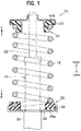
FIG. 1 is a cross-sectional view of a suspension device including a lower-side spring-receiving member according to an embodiment of the present invention, and is also a diagram for describing a schematic configuration. -
FIG. 2A is a top perspective view of the lower-side spring-receiving member according to the embodiment of the present invention, andFIG. 2B is a cross-sectional view taken along line B-B inFIG. 2A . -
FIG. 3A is a bottom perspective view of the lower-side spring-receiving member according to the embodiment of the present invention;FIG. 3B is a bottom surface enlarged view of a slope portion ofFIG. 3A; FIG. 3C is a modification example of the bottom surface shown inFIG. 3B; FIG. 3D is another modification example of the bottom surface shown inFIG. 3B; and FIG. 3E is a cross sectional view taken along an arrow C - C ofFIG. 3B . -
FIGS. 4A and 4B are cross-sectional views of a case where a suspension spring is assembled to the recess portion inFIG. 3E ;FIG. 4A shows a diagram illustrating a state before a spring load is applied andFIG. 4B shows a diagram illustrating a state after a spring load is applied. -
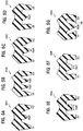
FIGS. 5A to 5G each is a cross-sectional view corresponding toFIG. 3E and illustrates a cross-sectional shape of a lower-side spring-receiving member according to a modification example of the embodiment of the present invention. -
FIGS. 6A to 6F each is a bottom surface enlarged view of a portion corresponding to the bottom surface shown inFIG. 3B and illustrates a shape of a recess portion of the lower-side spring-receiving member according to the modification example of the embodiment of the present invention;FIGS. 6G and 6H each is a diagram for explaining a further modification ofFIGS. 5A to 5G . -
FIG. 7A is a graph showing a load-deflection characteristic of the lower-side spring-receiving member according to the embodiment of the present invention illustrated byFIG. 3E , the modification example illustrated byFIG. 5A , and the comparative example.FIG. 7B is a graph showing load-deflection characteristics of the lower-side spring-receiving members according to the embodiment of the present invention illustrated inFIG. 3B , the modification example illustrated inFIG. 3C , and the modification example illustrated inFIG. 3D . - Now, a description is given of a lower-side spring-receiving member according to an embodiment of the present invention, taking a case in which the lower-side spring-receiving member is provided on a suspension device of an automobile as an example, with reference to the drawings appropriately as needed. It should be noted that this is merely an example of the embodiment. That is, the embodiment of the present invention can be applied to any vehicles equipped with a suspension device such as a two-wheeled automobile, an aircraft, an industrial machine such as a snow-compacting car, an agricultural machine, and MTB (mountain bike) and the like. In addition, it may be applied to a base isolation device or the like.
- Further, for convenience of explanation, the same members in the respective drawings are given the same reference numerals so that redundant explanations are omitted. In addition, in order to simplify the diagrams to make it easy to understand, descriptions of elemental components are partially omitted in each diagram. Direction axes for front and rear, top and bottom, and right and left are described in each drawing.
- In addition, in the following description, "a spring load of the lower-side spring-receiving member is OFF" (or, "before the spring load is applied") means a state in which the lower-side spring-receiving member is not mounted with a suspension spring 18 (see
FIG. 1 described below for details) or a state in which the lower-side spring-receiving member is mounted with asuspension spring 18 and only a load corresponding to a vehicle weight is applied. In addition, "the spring load of the lower-side spring-receiving member is ON" (or "after the spring load is applied") means a state in which thesuspension spring 18 is mounted on the lower-side spring-receiving member and a load greater than at least the vehicle weight is applied on the suspension spring and thesuspension spring 18 compresses. -
FIG. 1 is a cross-sectional view showing a schematic configuration of a suspension device including a lower-side spring-receiving member according to an embodiment of the present invention. - As shown in
FIG. 1 , thesuspension device 10 includes ashock absorber 16 and asuspension spring 18 suspended along an axial direction of theshock absorber 16. And, thesuspension device 10 includes an upper-side spring-receivingmember 34 and a lower-side spring-receivingmember 36 that receive a spring load F (see, for example,FIGS. 2A and4B described below), respectively at an upper end and a lower end portion of thesuspension spring 18. Note that the cross-sectional shape of the lower-side spring-receivingmember 36 shown inFIG. 1 corresponds to a cross sectional view taken along an arrow A-A inFIG. 2A described below. - The
shock absorber 16 is a device that attenuates vibration by performing motions of extension and contraction in conjunction with a movement of thesuspension spring 18 absorbing an impact force by an elastic force when a vehicle receives the impact force from a road surface. Theshock absorber 16 includes components (not shown), for example, a piston and a piston valve mechanism. These components generate a damping force in conjunction with the motions of extension and contraction, which damping force suppresses amplitude of the motions of extension and contraction. - In addition, the
shock absorber 16 includes anouter tube 20 and apiston rod 22. Theouter tube 20 is a cylindrical body and is equipped on the lower side. Thepiston rod 22 has one end housed inside theouter tube 20 and the other end protruding over a top of theouter tube 20. - In yet addition, an
annular step portion 26 is formed on the outer peripheral surface of theouter tube 20 of theshock absorber 16. And alower spring seat 28 is provided such as to be engaged with theannular step portion 26. Further, anupper spring seat 32 is provided to thepiston rod 22 so as to form a pair with thelower spring seat 28. Asuspension spring 18 is suspended between thelower spring seat 28 and theupper spring seat 32. A lower-side spring-receivingmember 36 is interposed between thelower spring seat 28 and the lower end portion of thesuspension spring 18. An upper-side spring-receivingmember 34 is interposed between theupper spring seat 32 and an upper end portion of thesuspension spring 18. - As shown in, for example,
FIG. 1 , the lower end portion of thesuspension spring 18 is supported by asupport surface 44a of thelower spring seat 28 via the lower-side spring-receivingmember 36; and the upper end portion of thesuspension spring 18 is supported by asupport surface 44b of theupper spring seat 32 via the upper-side spring-receivingmember 34. That is, the lower-side spring-receivingmember 36 and the upper-side spring-receivingmember 34 are members that function as a mounting member that receives the spring load F of thesuspension spring 18. In the description below, a term "support surface 44", when not particularly mentioned, refers to thesupport surface 44a. Details of the lower-side spring-receivingmember 36 are described below whenFIG. 2 is explained and thereafter. - Note that the lower-side spring-receiving
member 36 receives the elastic force generated by thesuspension spring 18 and is supported by thesupport surface 44 and thesuspension spring 18 therebetween. -
FIGS. 2A and 2B are views showing an upper side surface of the lower-side spring-receiving member according to the embodiment of the present invention;FIG. 2A is a perspective view, andFIG. 2B is a cross-sectional view taken along a line B-B ofFIGS. 2A . - As shown in
FIG. 2A , the lower-side spring-receivingmember 36 has a shape exhibiting a part of a circular ring (partially annular shape); and acurved surface 60 that is a guide surface in contact with thesuspension spring 18. Thecurved surface 60 has a diameter substantially the same as a spring diameter of thesuspension spring 18 in a top view and is a smooth surface formed so as to cave in an annular shape. The lower-side spring-receivingmember 36 has a base end portion ST formed on one end of the lower-side spring-receiving member and a slope portion SL formed on the other end of the lower-side spring-receiving member; and a spring holding portion HL between the base end portion ST and the slope portion SL. An end portion of thesuspension spring 18 is inserted and interposed by pressing into the base end portion ST. The base end portion ST of the lower-side spring-receivingmember 36 is formed in a wall shape with an opening that is formed by cutting out an upper portion (hereinafter referred to as "cutout opening"), and holds the end portion of thesuspension spring 18 from both sides of the base end portion ST. In addition, the above-described cutout opening of the base end portion ST has a shape in which end portions of the cutout opening is expanded toward both sides. This facilitates an insertion of the end portion of thesuspension spring 18 into the cutout opening, i.e., the base end portion ST of the lower-side spring-receivingmember 36, from an upper side of the lower-side spring-receivingmember 36; and further, facilitates pressing and interposing thesuspension spring 18 into thecurved surface 60 that is a guide surface curved in a substantially annular circle while rotating thesuspension spring 18 in a direction along the surface of the lower-side spring-receiving member 36 (a direction along the curved surface 60) around a point against which a tip of the end portion thesuspension spring 18 contacts. When interposing thesuspension spring 18, because the cutout opening is configured to be gradually narrowed, the lower-side spring-receivingmember 36 into which thesuspension spring 18 is interposed has a high holding performance of thesuspension spring 18. Details of the slope portion SL and the spring holding portion HL of the lower-side spring-receivingmember 36 are described below. - The length from the one end to the other end of the lower-side spring-receiving
member 36 is not specifically limited, but configured so as to be a length corresponding to, for example, approximately 0.6 to 0.7 turns of thesuspension spring 18. In the present embodiment, however, thesuspension spring 18 includes a rising portion T (detailed later) that rises at a predetermined slope in a spiral shape. In other words, a portion on and after the rising portion T of thesuspension spring 18 has a height that is considerably far apart from thesupport surface 44 of thelower spring seat 28. Therefore, the length from the one end to the other end of the lower-side spring-receivingmember 36 of this embodiment can be shorter than a length corresponding to one turn of thesuspension spring 18. This may result in a reduction of production cost such as material cost; and improving productivity by reducing manufacturing steps and shortening a manufacturing time. - Next, with reference to
FIG. 2A , a function of the spring holding portion HL is explained. - The spring holding portion HL includes a
bottom surface portion 46 having a flat surface, and a first and second extendingportions bottom surface portion 46 outside an periphery of thesuspension spring 18 and extend from the outer peripheral edge of thebottom surface portion 46 toward thesuspension spring 18. - In addition, the spring holding portion HL also includes a first protruding
portion 54 that protrudes by a predetermined length Δh (also seeFIG. 3 ) from thebottom surface portion 46 toward thesupport surface 44 of the lower spring seat 28 (seeFIG. 1 ) under a position where the second extendingportion 64b is provided. - In addition, an inner peripheral surface that contacts the
suspension spring 18 includes acurved surface 60 formed so that thesuspension spring 18 can be interposed. - It should be noted that the first extending
portion 64a and the second extendingportion 64b form a pair and are disposed so as to face each other so that thesuspension spring 18 does not get out from the spring holding portion HL (so that thesuspension spring 18 does not get away from the curved surface 60). - When the lower-side spring-receiving
member 36 is mounted on a vehicle and thesuspension spring 18 repeats extension and contraction due to, for example, vibration caused by unevenness of a road surface, thesuspension spring 18 has an elastic force (spring force) generated accompanying the motion of extension and contraction. That is, a spring load F (see a broken line arrow inFIG. 2A ) is generated, which load F presses thebottom surface portion 46 toward the support surface 44 (seeFIG. 1 ) of thelower spring seat 28. - As a result, the second extending
portion 64b formed above the first protrudingportion 54 is displaced toward the first extendingportion 64a, such that a width (spacing interval) of anopening portion 50 of the inner peripheral surface of the spring holding portion HL is narrowed (see a solid arrow inFIG. 2A ). That is, when the spring load F is applied on the spring holding portion HL, the first extendingportion 64a and the second extendingportion 64b are non-elastically-deformable in a direction in which theopening portion 50 closes. This results in increasing the holding force against thesuspension spring 18. - Next is an explanation of
FIG. 2B , which is a cross-sectional view taken along the line B-B inFIG. 2A . Here, the line B-B is a line tracing the bottom portion of thecurved surface 60 that is formed to be curved so as to contact and guide an annular outer periphery of thesuspension spring 18 when thesuspension spring 18 is mounted on the lower-side spring-receivingmember 36. For reference, a sectional view of thesuspension spring 18 is also shown. - As shown in
FIG. 2B , thesuspension spring 18 according to the embodiment includes an end turn portion Z that is disposed so as to keep parallel to thesupport surface 44 of thelower spring seat 28 and is non-elastically-deformable. In addition, thesuspension spring 18 includes a rising portion T rising from the end turn portion Z at a predetermined slope. Here, the end turn portion Z of thesuspension spring 18 is not limited to have a specific length, but in the present embodiment, formed to have a length corresponding to, for example, approximately 0.5 turns (half a circle). - Further, the lower-side spring-receiving
member 36 is interposed between thesuspension spring 18 and thesupport surface 44 of thelower spring seat 28 having the above-described shape (seeFIG. 1 ). As shown inFIG. 2B , the lower-side spring-receivingmember 36 has a shape corresponding to the shape of thesuspension spring 18, the shape extending from the end turn portion Z to the rising portion T. That is, the lower-side spring-receivingmember 36 has a flat portion FL corresponding to the end turn portion Z of thesuspension spring 18, which flat portion FL, including the base end portion ST, has a thickness of h1 that is substantially uniform in a cross sectional view. And, a portion corresponding to the rising portion T is a slope portion SL, which has a cross-sectional view of substantially slope shape inclined with respect to the bottom surface portion 46 (described below for details) and has a thickness gradually increasing from h1 to h2. Note that h1 < h2. In this way, the lower-side spring-receivingmember 36 includes the flat portion FL and the slope portion SL, and the slope portion SL is configured to vary in its thickness. - The embodiment of the present invention uses, for example, a rubber pad molded of an elastic member such as a hard rubber as the lower-side spring-receiving
member 36, but note that material of the lower-side spring-receivingmember 36 is not limited thereto. - Next, referring to
FIGS. 3A to 3E , description is made of a structure of the lower-side spring-receiving member according to the embodiment of the present invention when viewed from the bottom side. Here,FIG. 3A is a perspective view;FIG. 3B is an enlarged view of a slope portion inFIG. 3A; FIG. 3C is a modification example of the slope portion shown inFIG. 3B; FIG. 3D is another modification example of the slope portion shown inFIG. 3B; FIG. 3E is a cross-sectional view taken along an arrow C - C inFIG. 3B . - As shown in
FIG. 3A , the lower-side spring-receivingmember 36 according to the embodiment of the present invention includes abottom surface portion 46 that is formed to parallelly contact thesupport surface 44 of the lower spring seat 28 (seeFIG. 1 ) and substantially flat. Thisbottom surface portion 46 enables the lower-side spring-receivingmember 36 not to float with respect to the above-mentionedsupport surface 44 to receive thesuspension spring 18 stably when the spring load F is applied on the lower-side spring-receivingmember 36 from thesuspension spring 18. - Further, the
bottom surface portion 46 is formed to have widths in radial directions: a width W2 of the slope portion SL; a width W3 of the base end portion ST; and a width W1 of the flat portion FL except the base end portion ST, the width W1 being slightly narrower than the base end portion ST and the slope portion SL (i.e., W1 < W2, W3). The above object is to solve a problem that the slope portion SL and the base end portion ST are larger than other portions of thebottom surface portion 46 in the magnitude of the spring load F received from thesuspension spring 18. That is, as a received load is larger, the width of thebottom surface portion 46 in the radial direction is more widened so that the load can be received more evenly. Further, by widening more the radial direction width of and enlarging an area of the portion that receives a larger load in thebottom surface portion 46, more stable receipt of a large load can be done even if a deformation amount of thesuspension spring 18 increases. - It should be understood that a relationship between the widths W2 and W3 is not specifically limited and both widths may be substantially equal (W2 ≈ W3). The spring load F from the
suspension spring 18, however, is applied on the base end portion ST slightly more largely than on the slope portion SL. Therefore, it is more preferable to make the width W3 slightly wider than the width W2 (W2 ≦W3). - Next,
FIG. 3B shows an enlarged bottom view of the slope portion ofFIG. 3A . Thebottom surface portion 46 of the slope portion SL of the lower-side spring-receivingmember 36 according to the embodiment has a wall portion K formed at an end of the slope portion SL, and a recess portion Nk (indicated by a thick solid line) formed inside the wall portion K (seeFIG. 3E also for cross-reference). It should be noticed that the wall portion K exhibits a shape of spreading in a radial direction. A shape of the recess portion Nk is described below. - The wall portion K and the recess portion Nk are provided for a purpose of improving the deformation followability of the lower-side spring-receiving
member 36, for example, even when the deformation amount in a downward direction of thesuspension spring 18 increases. That is, for an example, even when thesuspension spring 18 is supposed to repeat alternately large deformations of extension and contraction in a short time, depression deformation is achieved by the recess portion Nk. In the depression deformation, the lower-side spring-receivingmember 36 is compressed and depressed immediately. Further, the wall portion K allows achieving return deformation in which the lower-side spring-receivingmember 36 rapidly returns to a previous state before the depression occurs. As described above, the wall portion K and the recess portion Nk provided on the bottom side of the slope portion SL of the lower-side spring-receivingmember 36 provides an action and effect in which the lower-side spring-receivingmember 36 can follow a large deformation movement of thesuspension spring 18 without any delay; and these action and effect do not provide a room for causing a gap to be formed between the lower-side spring-receivingmember 36 and thesuspension spring 18. If no gap is formed, foreign matter such as sand or gravel is never bitten between thesuspension spring 18 and the lower-side spring-receivingmember 36, which provides an effect of decreasing a possibility of corrosion and breakage occurring due to abrasion of the coating film of thesuspension spring 18. - It should be understood that the wall portion K preferably has no communication hole perforated thereon that communicates with the recess portion Nk. The reason is because if no communication hole is bored, the strength of the wall portion K is increased, resulting in increasing a followability of return deformation of the lower-side spring-receiving
member 36 to the contraction deformation of thesuspension spring 18. However, the wall portion K is not limited specifically to the above preferable feature of the wall portion K. - Further, as indicated by a thick solid line in
FIG. 3B , the recess portion Nk is formed, for example, along the circumferential direction of the lower-side spring-receivingmember 36, and has a substantially wedge shape growing wider toward the end of the lower-side spring-receivingmember 36. In other words, the recess portion Nk is of a substantially wedge form and has a shape in which its center line passing its top is curved such as to be equivalent to a curvature of a center line of thebottom surface portion 46. A specific recess shape of the recess portion Nk may be formed in a shape in which, for example, a ridge portion Rd forming a projection portion and trough portions Tr forming a valley portion are formed in a part of the recess portion (for details, refer toFIG. 3E described below); but is not limited thereto. - Furthermore, a modification of the recess portion of
FIG. 3B is shown inFIG. 3C , and another modification of the recess portion ofFIG. 3B is shown inFIG. 3D . The recess portion Nk1 ofFIG. 3C has a substantially rhombic shape as a whole, and is formed by replacing a portion near the wall portion K of the recess portion Nk ofFIG. 3B with a wedge-shape portion similar to a reversed shape of the recess portion Nk inFIG. 3B . Other features of the recess portion Nk1 ofFIG. 3C are the same as those of the recess portion NK inFIG. 3B . Further, on the contrary toFIG. 3C , the recess portion Nk2 shown inFIG. 3D has a substantially rectangular shape as a whole, and is formed by replacing the wedge-shape portion at a top side of the recess portion Nk ofFIG. 3B with a substantially rectangular shape similar to the shape of the portion near the wall portion K of the recess portion Nk ofFIG. 3B . Other features of the recess portion Nk2 ofFIG. 3D are the same as those of the recess portion Nk ofFIG. 3B . Such a recess portion Nk2 may be used. - As described above, the recess portion Nk may be formed to exhibit, for example a substantially wedge-like shape, a substantially rhombic shape, or a substantially rectangular shape. In this way, the strength of the wall portion K can be as desired strength, and the preferable return deformation of the lower-side spring-receiving
member 36 following the contraction deformation of thesuspension spring 18 can be achieved. Further, because the lower-side spring-receivingmember 36 can be recessed by a recessed volume determined by the shape of the recess portion Nk, the preferable depression deformation of the lower-side spring-receivingmember 36 can be achieved in response to the extensional deformation of thesuspension spring 18. - A load-deflection characteristic diagram for each case shown in
FIG. 3B, FIG. 3C, and FIG. 3D is shown respectively in each graph of (V), (IV), and (VI) inFIG. 7B. FIG. 7B shows a tendency that the magnitude of the reaction force applied gradually increases as the recessed volume decreases, for example, in an order ofFIG. 3D >FIG. 3B >FIG. 3C , for the same amount of deflection. Further, as the recessed volume becomes smaller, the magnitude of the reaction force to the maximum amount of deflection gradually increases. This means that an appropriate selection of the shape of the recess portion having a desired load-deflection characteristic provides an action and effect of further improving the followability of the lower-side spring-receivingmember 36 to thesuspension spring 18; and in addition, an effect of improving the drive feeling of crew members and reducing a feeling such as bottom-touching uncomfortableness. - Next, with reference to
FIG. 3E , description is given of a specific recess shape of the recess portion Nk.FIG. 3E shows a cross-sectional view taken along an arrow line, for example, C-C ofFIG. 3B , D-D ofFIG. 3C , and E-E ofFIG. 3D . - The recess portion Nk may be formed in a shape in which, for example, the ridge portion Rd forming a projection portion has both sides formed with trough portions Tr forming valley portions in a cross-sectional view.
- Here, the ridge portion Rd is formed to be in contact with the
support surface 44 of the lower spring seat 28 (seeFIG. 1 ), but not specifically limited thereto. However, the above-described shape in which the ridge portion Rd is formed to be in contact with thesupport surface 44 allows the spring load F to be received by three points of the right and left side walls S1, S2 and the ridge portion Rd of the lower-side spring-receiving member 36 (for details, seeFIGS. 4B ). This case is preferable to the case of two-point support (no support by the ridge portion Rd) in the following specific points: providing an effect of making the crew member feel none of the bottom-touching uncomfortableness because the three-point support more gradually increases the reaction force applied on thesuspension spring 18 than the two-point support when the lower-side spring-receivingmember 36 is compressed by depression deformation thereof (i.e., unlike the graph (III) of the comparative example inFIG. 7A in which the reflection force abruptly increases at a deflection amount T2, the reflection force gradually and smoothly increases as a whole as illustrated by the one dot chain line (I) inFIG. 7A ). Thus, the drive feeling can be improved. Further, an effect of restricting the lower-side spring-receivingmember 36 from compressing at an oblique angle due to the spring load F is suppressed. Furthermore, because the recessed volume is smaller than the comparative example, the magnitude of the reaction force for the maximum deflection amount can be larger than that of the comparative example. - Note that when the trough portion Tr is formed by recessing, chamfering process is preferably performed so that the trough portion Tr has a corner shaped in round. Such a chamfering process prevents cracks from being formed at the trough portion Tr to avoid the lower-side spring-receiving
member 36 from being ruptured. - Next, referring to
FIGS. 4A and 4B , description is given of a function of the slope portion SL of the lower-side spring-receivingmember 36.FIGS. 4A and 4B are cross-sectional views when the suspension spring is assembled onto the lower-side spring-receivingmember 36 inFIG. 3E ;FIG. 4A shows a state before a spring load is applied; andFIG. 4B shows a state after the spring load is applied. -
FIG. 4A shows a case before the lower-side spring-receivingmember 36 is mounted on a vehicle. In this case, the lower-side spring-receivingmember 36 is in contact with thesupport surface 44 of thelower spring seat 28 on three points: the side walls S1 and S2, and the protrusion portion, i.e., the ridge portion Rd. The ridge portion Rd according to the embodiment is adapted to have a substantially mountain shape in a cross sectional view in the radial direction as described above. That is, the ridge portion Rd has a shape in which a width of a cross-sectional surface when being cut at a plane parallel to thesupport surface 44 of thelower spring seat 28 gradually increases in an upward direction. - When the spring load F is applied onto the lower-side spring-receiving
member 36 that has been in the above state, the lower-side spring-receivingmember 36 is pressed downward and the right and left side walls S1 and S2 and the ridge portion Rd are compressed. At this time, the ridge portion Rd is in surface-contact with thesupport surface 44 at a predetermined width in a cross-sectional view (a state ofFIG. 4A appears as in line-contact in a cross-sectional view). As described above, the cross sectional width (lateral width) of the ridge portion Rd gradually increases toward the upper side. Therefore, even if the deflection of the lower-side spring-receivingmember 36 can have been temporarily neglected, as the extension deformation of thesuspension spring 18 increases, the width (lateral width) by which the ridge portion Rd contacts with thesupport surface 44 increases. This may make the lower-side spring-receivingmember 36 of the present embodiment surface-contact with thesupport surface 44 by an area corresponding to the magnitude of the spring load F, and gradually increase the reaction force to thesuspension spring 18 so as to be less likely to be compressed. - The above features of the embodiment provides an action and effect that the lower-side spring-receiving
member 36 can follow even an abrupt short-time shift of the deformation of thesuspension spring 18 from extension to contraction of returning to the original shape without causing a gap to be formed between thesuspension spring 18 and the lower-side spring-receivingmember 36, and leading to an effect of preventing foreign matter such as sand and gravel from being bitten between thesuspension spring 18 and the lower-side spring-receivingmember 36, and further an effect of preventing abrasion of coating and an occurrence of corrosion and breakage due to the abrasion of coating. - In addition, because the followability of the lower-side spring-receiving
member 36 responding the deformation of thesuspension spring 18 is improved, there is provided with an action and effect of reducing the bottom-touching uncomfortableness that a crew member receive from the vehicle, and improving the drive feeling. - Specifically explaining, for example, if no ridge portion Rd is provided, when the lower-side spring-receiving
member 36 is compressed such that an upper side surface of the recess portion Nk contacts thesupport surface 44, a reaction force to thesuspension spring 18 is jumped up to provide the bottom-touching uncomfortableness to the crew member. - On the other hand, the lower-side spring-receiving
member 36 according to the embodiment is provided with the ridge portion Rd in the recess portion Nk. In such a configuration, although the ridge portion Rd is compressed when the lower-side spring-receivingmember 36 is compressed, the reaction force applied to thesuspension spring 18 becomes larger as the compression of the ridge portion Rd reaches closer to its root, i.e., the ridge portion Rd is compressed more deeply. That is, because the reaction force to thesuspension spring 18 gradually increases due to the ridge portion Rd when the lower-side spring-receivingmember 36 according to the embodiment is compressed, this provides an action and effect of making the crew members hardly having the bottom-touching uncomfortableness comparing the previous case of no ridges. -
FIGS. 5A to 5G are diagrams showing cross-sectional shapes of modifications of the lower-side spring-receiving member according to the embodiment of the present invention, and each is a cross-sectional view of a portion corresponding to the portion shown inFIG. 3E . Note that an illustration of thesupport surface 44 of the lower spring seat 28 (seeFIG. 1 ) is omitted. - As shown in
FIGS. 5A to 5G , the cross-sectional shape of the slope portion SL of the lower-side spring-receivingmember 36 according to the present embodiment may have various modifications thought of. The following description of each modification focuses on a difference from the other modifications of the lower-side spring-receiving member. - In a lower-side spring-receiving
member 36A shown inFIG. 5A , as compared to the lower-side spring-receivingmember 36 shown inFIG. 3E , a ridge portion Rd1 corresponds to the ridge portion Rd; Rd1 is lower than Rd in height; and Rd1 is not in contact with thesupport surface 44 when the spring load F is not applied. In this case, as shown by a thin solid line (II) inFIG. 7A , when the spring load F is applied, the ridge portion Rd1 is depressed until contacting the support surface 44 (deflection amount: T1), and exhibits a load-deflection characteristic such that an elastic modulus gradually increases bit-by-bit after the ridge portion Rd1 contacts thesurface 44. That is,FIG. 7A shows that the lower-side spring-receivingmember 36A shown inFIG. 5A is depressed more gracefully than the lower-side spring-receivingmember 36 of the embodiment shown inFIG. 3E . However, there is no leap point of the reaction force as seen in the comparative example (deflection amount: T2), and thus, the lower-side spring-receivingmember 36A may provide the drive feeling without the bottom-touching uncomfortableness similarly to the lower-side spring-receivingmember 36 of the embodiment ofFIG. 3E . Further, because the lower-side spring-receivingmember 36A is smaller than the comparative example in the recessed volume, the magnitude of the reaction force at the time of the maximum amount of deflection can be larger than that of the comparative example. Such a lower-side spring-receivingmember 36A may be used. It should be understood thatFIG. 7A shows a graph of the present modification according to the embodiment slightly shifted from a graph of the comparative example until the deflection point: T1, but these two graphs actually show substantially same characteristics of the present modification and the comparative example. - Next, in the lower-side spring-receiving
member 36B shown inFIG. 5B , as compared to the lower-side spring-receivingmember 36A, portions corresponding to the ridge portion Rd1 are ridge portions Rd2 and Rd3, that is, the number of ridge portions increases from one to two (or multiple). In this case, when the spring load F is applied, the ridge portions Rd2, the Rd3 are depressed until they contact thesupport surface 44, which results in a four-point support in which the right and left walls S1 and S2 and the ridge portions Rd2 and Rd3 support thesuspension spring 18. Consequently, the lower-side spring-receivingmember 36B may provide a crew member with a drive feeling which give bottom-touching uncomfortableness more hardly than the lower-side spring-receivingmember 36A, when the lower-side spring-receiving member is depressed. Such a lower-side spring-receivingmember 36B may be used. Note that the heights of the ridge portions Rd2 and Rd3 are illustrated as substantially equal, but not particularly limited thereto; and that the number of the ridge portions is not limited to two and more than two ridge portions may be included. - Next, the ridge portion Rd4 of the lower-side spring-receiving
member 36C shown inFIG. 5C , as compared to the ridge portion Rd of the lower-side spring-receivingmember 36, includes an end tip formed in a sharp corner without being rounded. The lower-side spring-receivingmember 36C having such a configuration may provide the crew members with substantially the same drive-feeling as the lower-side spring-receivingmember 36, and may be used for a modification of the present embodiment. - Next, in the lower-side spring-receiving
member 36D shown inFIG. 5D , as compared to the lower-side spring-receivingmember 36A, the ridge portion Rd1 is replaced by the ridge portion Rd5, and the end tip of the ridge portion Rd1 having the substantially mountain shape in cross sectional view is replaced by a chevron with a sharp corner without rounded. And, another difference is in that side surfaces facing the ridge portion Rd5 among the side surfaces defining the right and left side walls S1 and S2 are formed to be substantially perpendicular to thesupport surface 44. The lower-side spring-receivingmember 36D having such a configuration may provide the crew member with substantially the same drive-feeling as the lower-side spring-receivingmember 36A, and may be used for a modification of the present embodiment. - Next, in the lower-side spring-receiving
member 36E shown inFIG. 5E , as compared to the lower-side spring-receivingmember 36D, the ridge portion Rd5 that is configured to line-contact with thesupport surface 44 is replaced by the ridge portion Rd6 that is configured to surface-contact with thesupport surface 44 in the ON state of the spring load F. Note that a width of the cross-sectional surface when cutting the ridge portion Rd6 in a cutting plane parallel to thesupport surface 44 of thelower spring seat 28 is a predetermined constant width independent on the height of the cutting plane. When the spring load F is applied on such a configuration of lower-side spring-receivingmember 36E, the ridge portion Rd6 is depressed until the ridge portion Rd6 contacts thesupport surface 44, and exhibits a constant elastic modulus of a predetermined value after contacting thesupport surface 44. The lower-side spring-receivingmember 36E may provide a crew member with a drive feeling which give bottom-touching uncomfortableness further reduced comparing to the lower-side spring-receivingmember 36D, after the lower-side spring-receivingmember 36E is brought into a three-point support status in which the spring load F is received on three points of the right and left side walls S1 and S2, and the ridge portion Rd6. Such a lower-side spring-receivingmember 36B may be also used. - Next, the lower-side spring-receiving
member 36F shown inFIG. 5F , as compared to the lower-side spring-receivingmember 36E, is different in that the ridge portion Rd6 is replaced by a ridge portion Rd7. Note that a width of the cross-sectional surface when cutting the ridge portion Rd7 in a cutting plane parallel to thesupport surface 44 of thelower spring seat 28 is configured to gradually increase at a predetermined rate as advancing in a upper direction. That is, the ridge portion Rd7 has a tapered shape in a cross sectional view. It should be understood that the ridge portion Rd7 of the lower-side spring-receivingmember 36F is configured to have both features of the respective ridge portions Rd5 and Rd6 of the lower-side spring-receivingmembers member 36F may be used. - Next, the lower-side spring-receiving
member 36G shown inFIG. 5G has a recessed shape of the recess portion Nk defining the right and left side walls S1 and S2 that are different from the lower-side spring-receivingmember 36C. Specifically, the lower-side spring-receivingmember 36G is recessed so that side surfaces facing the ridge portion Rd8 among the side faces defining the right and left side walls S1 and S2 are parallel with the side surfaces of the ridge portion Rd8. Such a configuration, even if there occurs a mode in which the lower-side spring-receivingmember 36G is compressed in a direction oblique to thesupport surface 44, the tip of the ridge portion Rd8 is brought early into contact with the side walls S1 and S2, which restricts a further deformation in the right-left lateral direction. Note that the ridge portion Rd4 and the ridge portion Rd8 are adapted to exhibit substantially the same cross-sectional shapes. The lower-side spring-receivingmember 36G having such a configuration enables restricting more strongly the lower-side spring-receivingmember 36G from being compressed in the oblique direction than the lower-side spring-receivingmember 36C, and thus, may provide a better drive feeling to the crew members. Such a lower-side spring-receivingmember 36G may be used. - Actions and effects of the lower-side spring-receiving member according to the embodiment are summarized as follows.
- The lower-side spring-receiving
member 36 according to the embodiment of the present invention is configured to include the flat portion FL and the slope portion SL, as shown inFIGS. 2A and 2B . The flat portion FL includes the base end portion ST, the spring holding portion HL. The base end portion ST of the lower-side spring-receivingmember 36 is formed in a wall shape that has an opening formed by cutting out the upper portion of a mounting member to hold an end portion of thesuspension spring 18 from both sides of the wall shape. Further, this opening has a shape in which end portions are widened toward both sides, which makes it easy to insert and interpose by pressing an end portion of thesuspension spring 18. - Further, as shown in
FIG. 2A , the spring holding portion HL is configured so that a distance between the first extendingportion 64a and the second extendingportion 64b can be narrowed when the spring holding portion HL receives a spring load F. In other words, as the spring load F is greater, the distance between the first extendingportion 64a and the second extendingportion 64b is adapted to be narrowed. This results in an action and effect of achieving a strong holding of thesuspension spring 18. - Furthermore, as shown in
FIG. 2B , the lower-side spring-receivingmember 36 includes a slope portion SL having a slope shape in a cross sectional view and its thickness in a cross sectional view adapted to vary. In other words, the deformation followability of the lower-side spring-receivingmember 36 with respect to thesuspension spring 18 may be improved by changing the thickness of the lower-side spring-receivingmember 36 accompanying with a shape of thesuspension spring 18. This results in an effect of preventing the corrosion, breakage, and the like from occurring due to an abrasion of the coating caused by having sand and gravel into a gap between thesuspension spring 18 and lower-side spring-receivingmember 36. - Further, as shown in
FIG. 3A , thebottom surface portion 46 of the lower-side spring-receivingmember 36 according to the embodiment of the present invention is formed such that a width W1 of the flat portion FL except a width W2 of the slope portion SL and a width W3 of the base end portion ST is slightly narrower than the width of the slope portion SL and the base end portion ST (i.e., W1 < W2, W3). This provides an action and effect such that a load can be received more evenly even if the magnitude of the load applied from thesuspension spring 18 is different depending on a location. - Further, as shown in
FIG. 3B to FIG. 3E , thebottom surface portion 46 of the slope portion SL of the lower-side spring-receivingmember 36 according to the embodiment, has a wall portion K formed at an end of the slope portion SL, and a recess portion Nk (indicated by a thick solid line) formed inside the wall portion K. This provides an action and effect of providing no room causing a gap to be formed between the lower-side spring-receivingmember 36 and thesuspension spring 18. Forming no gap provides an action and effect of decreasing a possibility of corrosion and breakage occurring due to biting foreign matter such as gravel. In addition, the recess portion Nk may be formed in a shape in a cross-sectional view, in which, for example, the trough portions Tr forming valley portions are formed at both sides of the ridge portion Rd forming a projection portion. It may be enough for the recess portion Nk include at least one of ridge portion Rd that is in contact with the mounting surface on which the lower-side spring-receivingmember 36 is placed and a ridge portion Rd that is not in contact with the mounting surface. Such a configuration allows receiving a large spring load F by at least three-point support by the right and left side walls S1 and S2 and the ridge portion Rd of the lower-side spring-receivingmember 36. This enables more stable support than a two-point support. Consequently, any of the lower-side spring-receiving members according to the embodiment and its modifications of the present invention, as shown inFIG. 7A , provides an effect of enabling improvement of the driving feel of the crew members by gradually increasing the reaction force against thesuspension spring 18 relative to the comparative example. - Above described embodiment and modifications are described in detail for easy understanding of the present invention, and do not necessarily limit the present invention to those including all the elements described above.
- Further, some structures of one of the embodiments or modifications can be replaced by structures of another embodiment or modification, and a structure of an embodiment or modification can be added to structures of another embodiment or modification. Furthermore, some of the structures of embodiments or modifications can be added, deleted, or replaced with other structures.
- Specifically, the lower-side spring-receiving
member 36 according to the above embodiment is described such that the recess portion Nk is exemplified by the recess portion Nk, Nk1, or Nk2 illustrated respectively byFIG. 3B, FIG. 3C, and FIG. 3D , but the recess portion Nk is not limited thereto. - For example, as shown in
FIG. 6A , a recess portion Nk3 may be used, which has a shape of the wedge whose direction is reversed to that ofFIG. 3B . Specifically, this recess portion Nk3 may be formed such that a top of the wedge is reversed from that ofFIG. 3B to be located near the end of the lower-side spring-receivingmember 36. - In the same manner as
FIG. 6A , a recess portion Nk4 as shown inFIG. 6B may be used, which is in a shape that is reversed in its direction from that of the recess portion Nk1 shown inFIG. 3C . Specifically, the recess portion Nk4 may be formed such that a shape of a side of the recess portion Nk3 opposite to the wall portion K is made wedge-shaped like the top side of the recess portion Nk1 near the wall portion K and a whole shape of the recess portion Nk3 exhibits a rhombic shape. Other features of the recess portion Nk3 are the same as those of the recess portion Nk3 inFIG 6A . Even such a recess portion Nk4 can provide the same effects as those provided by the embodiment. - Further, the wall portion K of
FIG. 3B is described as being formed on one portion at the end of the slope portion SL of the lower-side spring-receivingmember 36, but not particularly limited thereto. For example, as in a recess portion Nk5 shown inFIG. 6C , in addition to the wall portion K formed at the end of the slope portion SL, a wall portion Kα may also be provided inside the recess portion Nk in a manner of extending in a shorter side direction of the recess portion Nk. In other words, the recess portion Nk may be provided with the wall portions K and Kα of shape extending in a radial direction. Furthermore, the wall portion Kα may be provided at a plurality of locations. It should be noted that the recess portion Nk5 shown inFIG. 6C is formed by providing the wall portion Kα extending in the shorter side direction inside the recess portion Nk shown inFIG. 3B . - Consequently, by combining the embodiment and modifications of the recess portion Nk with the configuration of the wall portion Kα (two options of providing and non-providing), for example; five shapes of the recess portion Nk shown in
FIGS. 3B to 3D andFIGS. 6A to 6B (Nk to Nk4); and eight types of radial cross-sectional shapes of the slope portion SL without taking into account the wall portions K and Kα, i.e., any one of 36 to 36G respectively shown inFIG. 3E , andFIG. 5A to FIG. 5G , the recess portion Nk can be configured in at least 80 types (2*5*8= 80) as a whole:. It should be understood that the wall portion K ofFIG. 3B can be regarded to be located on the end of the slope portion SL and at the same time provided on a position of the end of the recess portion Nk. - Furthermore, another modification of
FIG. 6C , as shown by a recess portion Nk6 ofFIG. 6D , may be configured to have the wall portion K formed at the end of the slope portion SL gotten rid of to include only the wall portion Kα provided inside the recess portion Nk. It should be understood that the recess portion Nk6 ofFIG. 6D can be obtained from the recess portion Nk2 shown inFIG. 3D , by providing the wall portion Kα extending in the short side direction inside the recess portion Nk2 and getting rid of the wall portion K located on the end of the slope portion SL. Note that a recess portion having the wall portion Kα other than the recess portion Nk2 may be thought of a configuration having the wall portion K gotten rid of. That is, combinations of five kinds of recess portions Nk to Nk4 and eight cross-sectional shapes of 36 to 36G can configure forty (5 * 8 = 40) configurations in total, each of which is provided with the wall portion Kα and gotten rid of the wall portion K. - Further, as a recess portion Nk7 shown in
FIG. 6E , the recess portion Nk3 ofFIG. 6A and a recess portion different from the Nk3, for example, the recess portion Nk shown inFIG. 3B , both may be provided such as to sandwich the wall portion Kα. - The above modifications allow an adjusting the reaction force applied to the
suspension spring 18 by ways such as increasing further a magnitude of the force, changing a position on which the reaction force is applied by providing the wall portions K and Kα to the recess portion Nk appropriately as needed, which, in other words, enables an adjustment so that of the lower-side spring-receivingmember 36 can achieve a much better return deformation, following the contraction deformation of thesuspension spring 18, thus such modifications are preferable. - Furthermore, another modification example of the recess portion Nk5 shown in
FIG. 6C may be configured, as shown in recess portions Nk8 ofFIG. 6F , such as to include a recess portion Nk8 formed on both sides of the wall portion Kα in the circumferential direction, a combination of the recess portions, each having a cross sectional shape in the radial direction different from each other. Specifically describing, for example, the recess portion Nk5 shown inFIG. 6C and the recess portion Nk8 shown in andFIG. 6F have a common feature that their outer shapes are common in including the wall portion Kα in the substantially wedge-shaped inner portion. On the contrary, the recess portion Nk5 has a common cross-sectional shape taken in the radial direction on both sides of the wall portion Kα in the circumferential direction, for example, the ridge portion Rd of the embodiment shown inFIG. 3E is provided on the both sides. On the other hand, the recess portion Nk8 is provided with, for example, the ridge portion Rd6 shown inFIG. 5E near the end of the slope portion SL from the wall portion Kα; and the ridge portion Rd of the embodiment shown inFIG. 3E on the opposite side. Note that the combination of the ridge portions Rd6 and Rd is merely an example and the reverse order configuration may be allowed or a combination other than the above may be, of course, allowed. That is, at least 8P2 = 8 x 7 = 56 types of cross-sectional shape combinations of the above cases can be thought of (two-pair combination of cross-sectional shapes: 36 to 36G). - The above discussion can be summarized that the embodiments of the present invention are thought of at least 176 types of combinations (i.e., 80 + 40 + 56 = 176).
- Further,
FIGS. 5D to 5G show examples having one ridge portion among the ridge portions Rd5 to Rd8 respectively, but a configuration having a plurality of ridge portions may be allowable. Such a configuration can be made by combining a mix of ridge portions Rd, each having different features such as height and shape in the cross sectional view taken along the radial direction. - Specifically, for example, a configuration may be made such that at least two or more of the ridge portions: Rd1, Rd5, Rd6, and Rd7 in
FIGS. 5A, 5D, 5E, and 5F are included in one lower-side spring-receivingmember 36. For example, as shown inFIG. 6G , the ridge portion Rd1 shown inFIG. 5A and the ridge portion Rd7 shown inFIG. 5F may be configured to be included in one lower-side spring-receivingmember 36H. It should be understood thatFIG. 6G may be regarded as a modification of the lower-side spring-receivingmember 36B inFIG. 5B . In other words,FIG. 6G may be regarded to show a configuration example formed by a combination of various types of ridge portions Rd unlikeFIG. 5B . - Further, other various types of configurations can be considered, for example, a configuration which includes the ridge portion Rd in
FIG. 3E and any one of the ridge portions: Rd5, Rd6, and Rd7 inFIGS. 5D, 5E, and 5F in one lower-side spring-receivingmember 36. In this configuration, for example, as shown in the lower-side spring-receivingmember 36I ofFIG. 6H , if a height of the ridge portion Rd that is positioned at a far side (i.e., inward in a radial direction) from the side wall of thelower spring seat 28 is made higher than that of the ridge portion near the side wall, the lower-side spring-receivingmember 36 can be made stronger against a contraction in the radial direction, i.e., the right-left direction, and thus, this configuration is preferable. Note thatFIG. 6H is a combination of the ridge portion Rd and the ridge portion Rd5, but the present invention may not be particularly limited thereto. - Consequently, the lower-side spring-receiving
member 36 according to the embodiment of the present invention may achieve a much better followability to the deformation of the suspension spring by appropriately selecting a combination of a shape of a radial cross-sectional plane and a shape of the bottom side in the recess portion so that the deflection amount to the load is optimized, and also provides an action and effect of further improving the drive feeling of the crew members. - In addition, the spring-receiving member according to an embodiment of the present invention is described as a lower-side spring-receiving
member 36, but may also be applied to the upper-side spring member 34. This case may be even more effective particularly for a vehicle having a lower vehicle height, because such a vehicle tends to be exposed under an environment in which sand or gravel relatively easily enter. -
- 10: suspension device
- 16: shock absorber
- 18: suspension spring
- 20: outer tube
- 22: piston rod
- 26: annular step portion
- 28: lower spring seat
- 32: upper spring seat
- 34: upper-side spring-receiving member
- 36, 36A, 36B, 36C, 36D, 36E, 36F, 36G, 36H, 36I: lower-side spring-receiving member
- 44, 44a, 44b: support surface (mounting surface)
- 46: bottom surface portion
- 50: opening portion
- 54: first protruding portion
- 60: curved surface
- 64a: first extending portion
- 64b: second extending portion
- F: spring load
- Z: end turn portion
- T: rising portion
- h1, h2: thickness
- W1, W2, W3: width
- ST: base end portion
- HL: spring holding portion (holding portion)
- SL: slope portion
- FL: flat portion
- K, Kα: wall portion
- S1, S2: side wall
- Nk, Nk1, Nk2, Nk3, Nk4, Nk5, Nk6, Nk7, Nk8: recess portion
- Rd, Rd1, Rd2, Rd3, Rd4, Rd5, Rd6, Rd7, Rd8: ridge portion
- Tr: trough portion
- Δh: predetermined length
Claims (9)
- A lower-side spring-receiving member, receiving a suspension spring at a lower side of the suspension spring that is structured to include a rising portion extending up from a non-elastically-deformable end turn portion of the suspension spring, the lower-side spring-receiving member and the suspension spring included in a suspension device, the lower-side spring-receiving member
having a partially annular shape, and
comprising:a base end portion arranged at one end of the lower-side spring-receiving member, wherein an end portion of the suspension spring is inserted in the base end portion;a slope portion arranged at the other end of the lower-side spring-receiving member and having a thickness in a cross-sectional view, the thickness varying in accordance with a shape of the rising portion of the suspension spring; anda holding portion arranged between the base end portion and the slope portion, and holding the suspension spring,whereinthe slope portion includes a recess portion formed on its bottom-surface;the recess portion includes: at least one of a ridge portion being formed in a substantially mountain shape in a cross-sectional view taken along a radial direction of the partially annular shape and in contact with a mounting surface on which the lower-side spring-receiving member is mounted when no spring load is applied from the suspension spring, and a ridge portion formed in a substantially mountain shape in a cross-sectional view taken along the radial direction and not being in contact with the mounting surface when no spring load is applied from the suspension spring; andthe ridge portion contacts the mounting surface and is deflected and compressed to apply a reaction force on the suspension spring when the spring load is applied on the lower-side spring-receiving member. - A lower-side spring-receiving member
having a partially annular shape; and
comprising:a base end portion arranged at one end of the lower-side spring-receiving member, wherein an end portion of a suspension spring structured to include a rising portion extending up from a non-elastically-deformable end turn portion of the suspension spring is inserted in the base end portion;a slope portion arranged at the other end of the lower-side spring-receiving member and having a thickness in a cross-sectional view, the thickness varying in accordance with a shape of the rising portion of the suspension spring; anda holding portion arranged between the base end portion and the slope portion, and holding the suspension spring,whereinthe slope portion includes a recess portion formed on its bottom-surface;the recess portion includes at least one ridge portion being formed in a substantially mountain shape in a cross-sectional view taken along a radial direction of the partially annular shape and in contact with a mounting surface on which the lower-side spring-receiving member is mounted when no spring load is applied from the suspension spring; andthe ridge portion contacting the mounting surface is deflected and compressed to apply a reaction force on the suspension spring when the spring load is applied on the lower-side spring-receiving member. - A lower-side spring-receiving member
having a partially annular shape; and
comprising:a base end portion arranged at one end of the lower-side spring-receiving member, wherein an end portion of a suspension spring structured to include a rising portion extending up from a non-elastically-deformable end turn portion of the suspension spring is inserted in the base end portion;a slope portion arranged at the other end of the lower-side spring-receiving member and having a thickness in a cross-sectional view, the thickness varying in accordance with a shape of the rising portion of the suspension spring; anda holding portion arranged between the base end portion and the slope portion, and holding the suspension spring,whereinthe slope portion includes a recess portion formed on its bottom-surface;the recess portion includes at least one ridge portion being formed in a substantially mountain shape in a cross-sectional view taken along a radial direction of the partially annular shape and not being in contact with a mounting surface on which the lower-side spring-receiving member is mounted when no spring load is applied from the suspension spring; andthe ridge portion contacts the mounting surface and is deflected and compressed to apply a reaction force on the suspension spring when the spring load is applied on the lower-side spring-receiving member. - The lower-side spring-receiving member according to any one of claims 1 to 3, wherein
the recess portion is configured to include a plurality of the ridge portions that are different from one another in heights or shapes in the cross-sectional view taken along the radial direction. - The lower-side spring-receiving member according to any one of claims 1 to 3, wherein
the ridge portion is configured to have a shape in which its width in the cross-sectional view taken along the radial direction increases in an upward direction so that a magnitude of the reaction force applied to the suspension spring gradually increases as the ridge portion is further compressed. - The lower-side spring-receiving member according to any one of claims 1 to 3, wherein
the recess portion is configured to have a substantially wedge shape, a substantially rhombic shape, or a substantially rectangular shape. - The lower-side spring-receiving member according to any one of claims 1 to 3, wherein
the recess portion is configured to have a wall portion having a shape extending in the radial direction. - The lower-side spring-receiving member according to claim 7, wherein
the wall portion is provided inside the recess portion. - The lower-side spring-receiving member according to claim 2 or claim 3, wherein
the lower-side spring-receiving member and the suspension spring are mounted on a suspension device.
Applications Claiming Priority (2)
| Application Number | Priority Date | Filing Date | Title |
|---|---|---|---|
| JP2015028306A JP6402046B2 (en) | 2015-02-17 | 2015-02-17 | Lower spring receiving member and suspension device |
| PCT/JP2016/053409 WO2016132925A1 (en) | 2015-02-17 | 2016-02-04 | Lower-side spring-receiving member |
Publications (3)
| Publication Number | Publication Date |
|---|---|
| EP3260728A1 true EP3260728A1 (en) | 2017-12-27 |
| EP3260728A4 EP3260728A4 (en) | 2018-11-21 |
| EP3260728B1 EP3260728B1 (en) | 2021-04-28 |
Family
ID=56688886
Family Applications (1)
| Application Number | Title | Priority Date | Filing Date |
|---|---|---|---|
| EP16752312.5A Active EP3260728B1 (en) | 2015-02-17 | 2016-02-04 | Lower-side spring-receiving member |
Country Status (9)
| Country | Link |
|---|---|
| US (1) | US10626942B2 (en) |
| EP (1) | EP3260728B1 (en) |
| JP (1) | JP6402046B2 (en) |
| CN (1) | CN107208729B (en) |
| BR (1) | BR112017016978B1 (en) |
| CA (1) | CA2976886C (en) |
| HU (1) | HUE054370T2 (en) |
| MX (1) | MX2017010584A (en) |
| WO (1) | WO2016132925A1 (en) |
Cited By (1)
| Publication number | Priority date | Publication date | Assignee | Title |
|---|---|---|---|---|
| FR3092635A1 (en) * | 2019-02-12 | 2020-08-14 | Sogefi Suspensions | Support element for coil spring, suspension assembly and suspension device including this support element |
Families Citing this family (8)
| Publication number | Priority date | Publication date | Assignee | Title |
|---|---|---|---|---|
| CA2976751C (en) * | 2015-02-17 | 2019-04-02 | Nhk Spring Co., Ltd. | Lower-side spring-receiving member |
| DE102016206891B3 (en) * | 2016-04-22 | 2017-04-27 | Zf Friedrichshafen Ag | Hydropneumatic strut |
| JP6956606B2 (en) * | 2017-11-23 | 2021-11-02 | 住友理工株式会社 | Seat rubber |
| JP7023201B2 (en) * | 2018-08-24 | 2022-02-21 | 日本発條株式会社 | Coil spring device for suspension |
| CN111188863A (en) * | 2018-11-14 | 2020-05-22 | 宝沃汽车(中国)有限公司 | Vehicle and shock absorber spring assembly thereof |
| DE102019208307A1 (en) * | 2019-06-06 | 2020-12-10 | Aktiebolaget Skf | Suspension axial bearing device and a strut equipped with such a device |
| JP2022059443A (en) * | 2020-10-01 | 2022-04-13 | 株式会社Subaru | Suspension device |
| DE102022209825A1 (en) * | 2022-09-19 | 2024-03-21 | Thyssenkrupp Ag | Self-closing channel |
Family Cites Families (21)
| Publication number | Priority date | Publication date | Assignee | Title |
|---|---|---|---|---|
| CH380546A (en) * | 1960-10-26 | 1964-07-31 | Gomma Antivibranti Applic | Anti-vibration rubber washer for coil spring suspensions |
| DE4211176C2 (en) * | 1992-04-03 | 1998-07-23 | Porsche Ag | Bearing for a shock absorber of a motor vehicle |
| DE19939515C2 (en) | 1999-08-20 | 2002-06-13 | Porsche Ag | Strut for a motor vehicle with a bearing for a coil spring |
| DE19960699B4 (en) * | 1999-12-16 | 2010-09-30 | Schaeffler Technologies Gmbh & Co. Kg | Strut bearing |
| DE10106915C2 (en) * | 2001-02-15 | 2003-02-13 | Benteler Automobiltechnik Gmbh | suspension arrangement |
| JP3820361B2 (en) * | 2001-10-16 | 2006-09-13 | 東海ゴム工業株式会社 | Spring seat rubber |
| JP4597723B2 (en) * | 2004-12-16 | 2010-12-15 | 株式会社ショーワ | Spring seat structure of hydraulic shock absorber |
| CN100451379C (en) * | 2005-09-15 | 2009-01-14 | 东洋橡胶工业株式会社 | Support |
| JP4636009B2 (en) * | 2006-02-21 | 2011-02-23 | 東海ゴム工業株式会社 | Spring seat for vehicle suspension |
| FR2901179B1 (en) * | 2006-05-16 | 2011-06-24 | Roulements Soc Nouvelle | VEHICLE SUSPENSION STOPPING DEVICE WITH REINFORCED SEALING |
| FR2904261B1 (en) * | 2006-07-26 | 2011-05-13 | Roulements Soc Nouvelle | STOPPER OF SUSPENSION AND SUSPENSION LEG WITH SUCH A ROCKET |
| CN201396389Y (en) * | 2009-02-24 | 2010-02-03 | 杭州钱江弹簧有限公司 | Spring with ends buckled outward |
| JP5644636B2 (en) * | 2011-03-30 | 2014-12-24 | オイレス工業株式会社 | Thrust slide bearing and combination mechanism of this thrust slide bearing and piston rod |
| JP5387606B2 (en) * | 2011-04-04 | 2014-01-15 | マツダ株式会社 | Vehicle suspension structure |
| CN106703281B (en) * | 2011-06-03 | 2019-04-12 | 赫库科技公司 | External for concrete stretches stiffening device |
| JP5950623B2 (en) * | 2012-02-28 | 2016-07-13 | オイレス工業株式会社 | Thrust sliding bearing and combination mechanism of thrust sliding bearing and piston rod |
| JP5889090B2 (en) * | 2012-04-04 | 2016-03-22 | 東洋ゴム工業株式会社 | Spring seat rubber |
| JP5646023B2 (en) * | 2013-03-12 | 2014-12-24 | 株式会社ショーワ | Elastic sheet and suspension device |
| JP5961128B2 (en) * | 2013-03-21 | 2016-08-02 | Kyb株式会社 | Spring rubber seat and strut suspension |
| JP6057814B2 (en) * | 2013-04-11 | 2017-01-11 | オイレス工業株式会社 | Synthetic plastic plain bearing |
| EP3002137B1 (en) * | 2014-09-30 | 2018-12-26 | Aktiebolaget SKF | Suspension bearing device, motor vehicle equipped with such a suspension bearing device and manufacturing method |
-
2015
- 2015-02-17 JP JP2015028306A patent/JP6402046B2/en active Active
-
2016
- 2016-02-04 WO PCT/JP2016/053409 patent/WO2016132925A1/en active Application Filing
- 2016-02-04 EP EP16752312.5A patent/EP3260728B1/en active Active
- 2016-02-04 MX MX2017010584A patent/MX2017010584A/en unknown
- 2016-02-04 US US15/551,455 patent/US10626942B2/en active Active
- 2016-02-04 BR BR112017016978-9A patent/BR112017016978B1/en active IP Right Grant
- 2016-02-04 CA CA2976886A patent/CA2976886C/en active Active
- 2016-02-04 CN CN201680010399.9A patent/CN107208729B/en active Active
- 2016-02-04 HU HUE16752312A patent/HUE054370T2/en unknown
Cited By (3)
| Publication number | Priority date | Publication date | Assignee | Title |
|---|---|---|---|---|
| FR3092635A1 (en) * | 2019-02-12 | 2020-08-14 | Sogefi Suspensions | Support element for coil spring, suspension assembly and suspension device including this support element |
| WO2020165534A1 (en) * | 2019-02-12 | 2020-08-20 | Sogefi Suspensions | Support element for a helical spring, suspension assembly and suspension device comprising said support element |
| CN113423968A (en) * | 2019-02-12 | 2021-09-21 | 索葛菲悬架公司 | Support element for a helical spring, suspension assembly and suspension device comprising said support element |
Also Published As
| Publication number | Publication date |
|---|---|
| CN107208729A (en) | 2017-09-26 |
| CA2976886A1 (en) | 2016-08-25 |
| JP2016151300A (en) | 2016-08-22 |
| US20180045263A1 (en) | 2018-02-15 |
| CN107208729B (en) | 2019-04-23 |
| EP3260728A4 (en) | 2018-11-21 |
| JP6402046B2 (en) | 2018-10-10 |
| BR112017016978B1 (en) | 2023-05-16 |
| HUE054370T2 (en) | 2021-09-28 |
| US10626942B2 (en) | 2020-04-21 |
| MX2017010584A (en) | 2018-07-06 |
| EP3260728B1 (en) | 2021-04-28 |
| CA2976886C (en) | 2019-05-21 |
| BR112017016978A2 (en) | 2018-04-03 |
| WO2016132925A1 (en) | 2016-08-25 |
Similar Documents
| Publication | Publication Date | Title |
|---|---|---|
| EP3260728B1 (en) | Lower-side spring-receiving member | |
| US7922157B2 (en) | Stopper for cylindrical elastic mount and cylindrical elastic mount assembly | |
| AU2008246060B2 (en) | Elastomeric pad for a compressible elastomeric spring | |
| EP1726505B1 (en) | Air spring | |
| CN103867522B (en) | Fluid pressure cylinder | |
| US20120104120A1 (en) | Two-phase spring | |
| CN111231787B (en) | Reclining device for vehicle seat | |
| US20100284733A1 (en) | Axial Ball Joint with Impact Damping Mechanism | |
| US20150176670A1 (en) | Wave spring having a linear characteristic in some regions | |
| JP3937042B2 (en) | Strut mount | |
| US10704634B2 (en) | Lower-side spring-receiving member | |
| CN102653230A (en) | Mounting structure of buffer member for fuel tank | |
| CN210591270U (en) | Vehicle bushing with asymmetric characteristics | |
| US20020053495A1 (en) | Hydraulic shock-absorber | |
| US20230116979A1 (en) | Recliner for vehicle | |
| CN111065839B (en) | Hydraulic main body mounting seat | |
| JP4291347B2 (en) | Vibration isolator | |
| KR20160126134A (en) | Spring pad for auto mobile suspension system | |
| JP7284715B2 (en) | strut mount | |
| JP4870028B2 (en) | Vibration isolator | |
| US20230051535A1 (en) | Seat recliner for vehicles | |
| JP2006281811A (en) | Bump stopper | |
| KR20210036560A (en) | Spring lower seat of strut for vehicle | |
| JP3965673B2 (en) | Bound stopper | |
| JP2007509599A (en) | Electric motor with axial clearance structure |
Legal Events
| Date | Code | Title | Description |
|---|---|---|---|
| STAA | Information on the status of an ep patent application or granted ep patent |
Free format text: STATUS: THE INTERNATIONAL PUBLICATION HAS BEEN MADE |
|
| PUAI | Public reference made under article 153(3) epc to a published international application that has entered the european phase |
Free format text: ORIGINAL CODE: 0009012 |
|
| STAA | Information on the status of an ep patent application or granted ep patent |
Free format text: STATUS: REQUEST FOR EXAMINATION WAS MADE |
|
| 17P | Request for examination filed |
Effective date: 20170915 |
|
| AK | Designated contracting states |
Kind code of ref document: A1 Designated state(s): AL AT BE BG CH CY CZ DE DK EE ES FI FR GB GR HR HU IE IS IT LI LT LU LV MC MK MT NL NO PL PT RO RS SE SI SK SM TR |
|
| AX | Request for extension of the european patent |
Extension state: BA ME |
|
| DAV | Request for validation of the european patent (deleted) | ||
| DAX | Request for extension of the european patent (deleted) | ||
| A4 | Supplementary search report drawn up and despatched |
Effective date: 20181023 |
|
| RIC1 | Information provided on ipc code assigned before grant |
Ipc: B60G 11/16 20060101ALI20181017BHEP Ipc: F16F 1/12 20060101ALI20181017BHEP Ipc: F16F 9/32 20060101AFI20181017BHEP Ipc: B60G 15/06 20060101ALI20181017BHEP Ipc: F16F 9/512 20060101ALI20181017BHEP |
|
| RIC1 | Information provided on ipc code assigned before grant |
Ipc: F16F 9/512 20060101ALI20200819BHEP Ipc: F16F 1/12 20060101ALI20200819BHEP Ipc: F16F 9/32 20060101AFI20200819BHEP Ipc: B60G 15/06 20060101ALI20200819BHEP Ipc: B60G 11/16 20060101ALI20200819BHEP |
|
| GRAP | Despatch of communication of intention to grant a patent |
Free format text: ORIGINAL CODE: EPIDOSNIGR1 |
|
| STAA | Information on the status of an ep patent application or granted ep patent |
Free format text: STATUS: GRANT OF PATENT IS INTENDED |
|
| INTG | Intention to grant announced |
Effective date: 20201002 |
|
| GRAJ | Information related to disapproval of communication of intention to grant by the applicant or resumption of examination proceedings by the epo deleted |
Free format text: ORIGINAL CODE: EPIDOSDIGR1 |
|
| STAA | Information on the status of an ep patent application or granted ep patent |
Free format text: STATUS: REQUEST FOR EXAMINATION WAS MADE |
|
| GRAP | Despatch of communication of intention to grant a patent |
Free format text: ORIGINAL CODE: EPIDOSNIGR1 |
|
| INTC | Intention to grant announced (deleted) | ||
| STAA | Information on the status of an ep patent application or granted ep patent |
Free format text: STATUS: GRANT OF PATENT IS INTENDED |
|
| INTG | Intention to grant announced |
Effective date: 20210218 |
|
| GRAS | Grant fee paid |
Free format text: ORIGINAL CODE: EPIDOSNIGR3 |
|
| GRAA | (expected) grant |
Free format text: ORIGINAL CODE: 0009210 |
|
| STAA | Information on the status of an ep patent application or granted ep patent |
Free format text: STATUS: THE PATENT HAS BEEN GRANTED |
|
| AK | Designated contracting states |
Kind code of ref document: B1 Designated state(s): AL AT BE BG CH CY CZ DE DK EE ES FI FR GB GR HR HU IE IS IT LI LT LU LV MC MK MT NL NO PL PT RO RS SE SI SK SM TR |
|
| REG | Reference to a national code |
Ref country code: GB Ref legal event code: FG4D |
|
| REG | Reference to a national code |
Ref country code: CH Ref legal event code: EP |
|
| REG | Reference to a national code |
Ref country code: DE Ref legal event code: R096 Ref document number: 602016056910 Country of ref document: DE |
|
| REG | Reference to a national code |
Ref country code: AT Ref legal event code: REF Ref document number: 1387408 Country of ref document: AT Kind code of ref document: T Effective date: 20210515 |
|
| REG | Reference to a national code |
Ref country code: IE Ref legal event code: FG4D |
|
| REG | Reference to a national code |
Ref country code: LT Ref legal event code: MG9D |
|
| REG | Reference to a national code |
Ref country code: HU Ref legal event code: AG4A Ref document number: E054370 Country of ref document: HU |
|
| REG | Reference to a national code |
Ref country code: AT Ref legal event code: MK05 Ref document number: 1387408 Country of ref document: AT Kind code of ref document: T Effective date: 20210428 |
|
| PG25 | Lapsed in a contracting state [announced via postgrant information from national office to epo] |
Ref country code: HR Free format text: LAPSE BECAUSE OF FAILURE TO SUBMIT A TRANSLATION OF THE DESCRIPTION OR TO PAY THE FEE WITHIN THE PRESCRIBED TIME-LIMIT Effective date: 20210428 Ref country code: AT Free format text: LAPSE BECAUSE OF FAILURE TO SUBMIT A TRANSLATION OF THE DESCRIPTION OR TO PAY THE FEE WITHIN THE PRESCRIBED TIME-LIMIT Effective date: 20210428 Ref country code: BG Free format text: LAPSE BECAUSE OF FAILURE TO SUBMIT A TRANSLATION OF THE DESCRIPTION OR TO PAY THE FEE WITHIN THE PRESCRIBED TIME-LIMIT Effective date: 20210728 Ref country code: FI Free format text: LAPSE BECAUSE OF FAILURE TO SUBMIT A TRANSLATION OF THE DESCRIPTION OR TO PAY THE FEE WITHIN THE PRESCRIBED TIME-LIMIT Effective date: 20210428 Ref country code: LT Free format text: LAPSE BECAUSE OF FAILURE TO SUBMIT A TRANSLATION OF THE DESCRIPTION OR TO PAY THE FEE WITHIN THE PRESCRIBED TIME-LIMIT Effective date: 20210428 Ref country code: NL Free format text: LAPSE BECAUSE OF FAILURE TO SUBMIT A TRANSLATION OF THE DESCRIPTION OR TO PAY THE FEE WITHIN THE PRESCRIBED TIME-LIMIT Effective date: 20210428 |
|
| PG25 | Lapsed in a contracting state [announced via postgrant information from national office to epo] |
Ref country code: GR Free format text: LAPSE BECAUSE OF FAILURE TO SUBMIT A TRANSLATION OF THE DESCRIPTION OR TO PAY THE FEE WITHIN THE PRESCRIBED TIME-LIMIT Effective date: 20210729 Ref country code: LV Free format text: LAPSE BECAUSE OF FAILURE TO SUBMIT A TRANSLATION OF THE DESCRIPTION OR TO PAY THE FEE WITHIN THE PRESCRIBED TIME-LIMIT Effective date: 20210428 Ref country code: IS Free format text: LAPSE BECAUSE OF FAILURE TO SUBMIT A TRANSLATION OF THE DESCRIPTION OR TO PAY THE FEE WITHIN THE PRESCRIBED TIME-LIMIT Effective date: 20210828 Ref country code: PL Free format text: LAPSE BECAUSE OF FAILURE TO SUBMIT A TRANSLATION OF THE DESCRIPTION OR TO PAY THE FEE WITHIN THE PRESCRIBED TIME-LIMIT Effective date: 20210428 Ref country code: PT Free format text: LAPSE BECAUSE OF FAILURE TO SUBMIT A TRANSLATION OF THE DESCRIPTION OR TO PAY THE FEE WITHIN THE PRESCRIBED TIME-LIMIT Effective date: 20210830 Ref country code: NO Free format text: LAPSE BECAUSE OF FAILURE TO SUBMIT A TRANSLATION OF THE DESCRIPTION OR TO PAY THE FEE WITHIN THE PRESCRIBED TIME-LIMIT Effective date: 20210728 Ref country code: RS Free format text: LAPSE BECAUSE OF FAILURE TO SUBMIT A TRANSLATION OF THE DESCRIPTION OR TO PAY THE FEE WITHIN THE PRESCRIBED TIME-LIMIT Effective date: 20210428 Ref country code: SE Free format text: LAPSE BECAUSE OF FAILURE TO SUBMIT A TRANSLATION OF THE DESCRIPTION OR TO PAY THE FEE WITHIN THE PRESCRIBED TIME-LIMIT Effective date: 20210428 |
|
| REG | Reference to a national code |
Ref country code: NL Ref legal event code: MP Effective date: 20210428 |
|
| PG25 | Lapsed in a contracting state [announced via postgrant information from national office to epo] |
Ref country code: RO Free format text: LAPSE BECAUSE OF FAILURE TO SUBMIT A TRANSLATION OF THE DESCRIPTION OR TO PAY THE FEE WITHIN THE PRESCRIBED TIME-LIMIT Effective date: 20210428 Ref country code: ES Free format text: LAPSE BECAUSE OF FAILURE TO SUBMIT A TRANSLATION OF THE DESCRIPTION OR TO PAY THE FEE WITHIN THE PRESCRIBED TIME-LIMIT Effective date: 20210428 Ref country code: SM Free format text: LAPSE BECAUSE OF FAILURE TO SUBMIT A TRANSLATION OF THE DESCRIPTION OR TO PAY THE FEE WITHIN THE PRESCRIBED TIME-LIMIT Effective date: 20210428 Ref country code: SK Free format text: LAPSE BECAUSE OF FAILURE TO SUBMIT A TRANSLATION OF THE DESCRIPTION OR TO PAY THE FEE WITHIN THE PRESCRIBED TIME-LIMIT Effective date: 20210428 Ref country code: CZ Free format text: LAPSE BECAUSE OF FAILURE TO SUBMIT A TRANSLATION OF THE DESCRIPTION OR TO PAY THE FEE WITHIN THE PRESCRIBED TIME-LIMIT Effective date: 20210428 Ref country code: DK Free format text: LAPSE BECAUSE OF FAILURE TO SUBMIT A TRANSLATION OF THE DESCRIPTION OR TO PAY THE FEE WITHIN THE PRESCRIBED TIME-LIMIT Effective date: 20210428 Ref country code: EE Free format text: LAPSE BECAUSE OF FAILURE TO SUBMIT A TRANSLATION OF THE DESCRIPTION OR TO PAY THE FEE WITHIN THE PRESCRIBED TIME-LIMIT Effective date: 20210428 |
|
| REG | Reference to a national code |
Ref country code: DE Ref legal event code: R097 Ref document number: 602016056910 Country of ref document: DE |
|
| PLBE | No opposition filed within time limit |
Free format text: ORIGINAL CODE: 0009261 |
|
| STAA | Information on the status of an ep patent application or granted ep patent |
Free format text: STATUS: NO OPPOSITION FILED WITHIN TIME LIMIT |
|
| 26N | No opposition filed |
Effective date: 20220131 |
|
| PG25 | Lapsed in a contracting state [announced via postgrant information from national office to epo] |
Ref country code: IS Free format text: LAPSE BECAUSE OF FAILURE TO SUBMIT A TRANSLATION OF THE DESCRIPTION OR TO PAY THE FEE WITHIN THE PRESCRIBED TIME-LIMIT Effective date: 20210828 Ref country code: AL Free format text: LAPSE BECAUSE OF FAILURE TO SUBMIT A TRANSLATION OF THE DESCRIPTION OR TO PAY THE FEE WITHIN THE PRESCRIBED TIME-LIMIT Effective date: 20210428 |
|
| PG25 | Lapsed in a contracting state [announced via postgrant information from national office to epo] |
Ref country code: IT Free format text: LAPSE BECAUSE OF FAILURE TO SUBMIT A TRANSLATION OF THE DESCRIPTION OR TO PAY THE FEE WITHIN THE PRESCRIBED TIME-LIMIT Effective date: 20210428 |
|
| PG25 | Lapsed in a contracting state [announced via postgrant information from national office to epo] |
Ref country code: MC Free format text: LAPSE BECAUSE OF FAILURE TO SUBMIT A TRANSLATION OF THE DESCRIPTION OR TO PAY THE FEE WITHIN THE PRESCRIBED TIME-LIMIT Effective date: 20210428 |
|
| REG | Reference to a national code |
Ref country code: CH Ref legal event code: PL |
|
| REG | Reference to a national code |
Ref country code: BE Ref legal event code: MM Effective date: 20220228 |
|
| PG25 | Lapsed in a contracting state [announced via postgrant information from national office to epo] |
Ref country code: LU Free format text: LAPSE BECAUSE OF NON-PAYMENT OF DUE FEES Effective date: 20220204 |
|
| PG25 | Lapsed in a contracting state [announced via postgrant information from national office to epo] |
Ref country code: LI Free format text: LAPSE BECAUSE OF NON-PAYMENT OF DUE FEES Effective date: 20220228 Ref country code: IE Free format text: LAPSE BECAUSE OF NON-PAYMENT OF DUE FEES Effective date: 20220204 Ref country code: CH Free format text: LAPSE BECAUSE OF NON-PAYMENT OF DUE FEES Effective date: 20220228 |
|
| PG25 | Lapsed in a contracting state [announced via postgrant information from national office to epo] |
Ref country code: BE Free format text: LAPSE BECAUSE OF NON-PAYMENT OF DUE FEES Effective date: 20220228 |
|
| PGFP | Annual fee paid to national office [announced via postgrant information from national office to epo] |
Ref country code: FR Payment date: 20230110 Year of fee payment: 8 |
|
| P01 | Opt-out of the competence of the unified patent court (upc) registered |
Effective date: 20230515 |
|
| PG25 | Lapsed in a contracting state [announced via postgrant information from national office to epo] |
Ref country code: MK Free format text: LAPSE BECAUSE OF FAILURE TO SUBMIT A TRANSLATION OF THE DESCRIPTION OR TO PAY THE FEE WITHIN THE PRESCRIBED TIME-LIMIT Effective date: 20210428 Ref country code: CY Free format text: LAPSE BECAUSE OF FAILURE TO SUBMIT A TRANSLATION OF THE DESCRIPTION OR TO PAY THE FEE WITHIN THE PRESCRIBED TIME-LIMIT Effective date: 20210428 |
|
| PGFP | Annual fee paid to national office [announced via postgrant information from national office to epo] |
Ref country code: HU Payment date: 20240111 Year of fee payment: 9 Ref country code: DE Payment date: 20231228 Year of fee payment: 9 Ref country code: GB Payment date: 20240108 Year of fee payment: 9 |