EP3260222A1 - Sprue structure for low-pressure die casting device and low-pressure die casting device having said sprue - Google Patents
Sprue structure for low-pressure die casting device and low-pressure die casting device having said sprue Download PDFInfo
- Publication number
- EP3260222A1 EP3260222A1 EP15882606.5A EP15882606A EP3260222A1 EP 3260222 A1 EP3260222 A1 EP 3260222A1 EP 15882606 A EP15882606 A EP 15882606A EP 3260222 A1 EP3260222 A1 EP 3260222A1
- Authority
- EP
- European Patent Office
- Prior art keywords
- molten metal
- sprue
- low
- casting device
- cavity
- Prior art date
- Legal status (The legal status is an assumption and is not a legal conclusion. Google has not performed a legal analysis and makes no representation as to the accuracy of the status listed.)
- Granted
Links
Images



Classifications
-
- B—PERFORMING OPERATIONS; TRANSPORTING
- B22—CASTING; POWDER METALLURGY
- B22C—FOUNDRY MOULDING
- B22C9/00—Moulds or cores; Moulding processes
- B22C9/08—Features with respect to supply of molten metal, e.g. ingates, circular gates, skim gates
- B22C9/082—Sprues, pouring cups
-
- B—PERFORMING OPERATIONS; TRANSPORTING
- B22—CASTING; POWDER METALLURGY
- B22D—CASTING OF METALS; CASTING OF OTHER SUBSTANCES BY THE SAME PROCESSES OR DEVICES
- B22D18/00—Pressure casting; Vacuum casting
- B22D18/04—Low pressure casting, i.e. making use of pressures up to a few bars to fill the mould
-
- B—PERFORMING OPERATIONS; TRANSPORTING
- B22—CASTING; POWDER METALLURGY
- B22C—FOUNDRY MOULDING
- B22C9/00—Moulds or cores; Moulding processes
- B22C9/08—Features with respect to supply of molten metal, e.g. ingates, circular gates, skim gates
-
- B—PERFORMING OPERATIONS; TRANSPORTING
- B22—CASTING; POWDER METALLURGY
- B22D—CASTING OF METALS; CASTING OF OTHER SUBSTANCES BY THE SAME PROCESSES OR DEVICES
- B22D18/00—Pressure casting; Vacuum casting
- B22D18/06—Vacuum casting, i.e. making use of vacuum to fill the mould
-
- B—PERFORMING OPERATIONS; TRANSPORTING
- B22—CASTING; POWDER METALLURGY
- B22D—CASTING OF METALS; CASTING OF OTHER SUBSTANCES BY THE SAME PROCESSES OR DEVICES
- B22D18/00—Pressure casting; Vacuum casting
- B22D18/08—Controlling, supervising, e.g. for safety reasons
Definitions
- the present invention relates to a sprue structure for a low-pressure casting device and a low-pressure casting device, in particular to a sprue structure that enables both reduction of the cycle time and prevention of oxidation of molten metal and a low-pressure casting device with the sprue.
- a low-pressure casting device typically includes a holding furnace for storing molten metal, a mold having a cavity and a stalk that communicates the holding furnace with a cavity, which is used for molding a casting by increasing the pressure in the holding furnace to supply the molten metal to the cavity through the stalk and allowing the molten metal to solidify.
- Patent Document 1 A casting device is disclosed in Patent Document 1, which includes a molten metal passage for supplying molten metal to a cavity, having a circular cross section perpendicular to the longitudinal direction.
- Patent Document 1 JP 2003-251453A
- a flat fan gate has been provided in a sprue to supply molten metal to a wide area.
- the cross-sectional shape of the molten metal passage greatly changes at the connection part between the sprue and the fan gate, the change of the flow rate of the molten metal causes ruffle in the molten metal surface, which may produce an oxide in the new surface of the molten metal and result in the degraded quality of molded products.
- increasing the supply rate of the molten metal is likely to cause large ruffle, it is difficult to achieve both reduction in supply time of the molten metal and reduction in oxide production.
- the present invention has been made in view of such problems with the prior art, and an object thereof is to provide a sprue for a low-pressure casting device which enables reduction of the cycle time and also prevents oxidation of molten metal and which hereby enables efficient production of high-quality molded products, and a low-pressure casting device with the sprue.
- the present inventors have found that the above-described object can be achieved by a molten metal reservoir of a sprue communicating a stalk with a cavity that is formed into a specific shape. The present invention was thus completed.
- the sprue structure for a low-pressure casting device of the present invention includes a molten metal reservoir that has a cross section perpendicular to the flow direction of molten metal such that the perimeter of the cross section gradually increases toward a cavity while the area of the cross section remains constant.
- the low-pressure casting device of the present invention includes the above-described sprue for a low-pressure casting device that communicates a stalk with a cavity of a mold.
- the cavity connection part has a flat shape. This enables supplying the molten metal to a wide area of the cavity, and the delivery is therefore improved. Further, this also reduces the change of the flow rate of the molten metal flowing through the sprue. Therefore, even when the supply rate of the molten metal is increased, production of further oxide is prevented since the molten metal does not ruffle, which enables production of high-quality molded products.
- FIG. 1 illustrates an example of the sprue 1 for a low-pressure casting device according to the present invention.
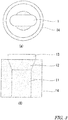
- FIG. 1 (a) is a front view of the sprue for a low-pressure casting device
- FIG. 1 (b) is a side view of the sprue for a low-pressure casting device.
- FIG. 1 (c) illustrates a cross section taken along A-A', i.e.
- FIG. 1 (d) illustrates a cross section taken along B-B', i.e. an example of the cross-sectional shape at the lower end of the molten metal reservoir 12.
- the sprue 1 for a low-pressure casting device includes a stalk connection part 11 that is connected to a stalk, the molten metal reservoir 12 and a cavity connection part 13 that is connected to a cavity.
- the shape of the molten metal reservoir 12 is such that the perimeter of a cross section perpendicular to the flow direction of molten metal gradually increases toward the cavity connection part 13 while the area of the cross section remains constant.
- the molten metal reservoir 12 has a shape such that the perimeter of the molten metal passage is longer at the lower end than at the upper end while the cross-sectional area of the molten metal passage remains the same, the change of the flow rate of the molten metal is reduced. Further, since the cavity connection part 13 that is disposed above the molten metal reservoir has a flat shape due to the long cross-sectional perimeter, which is described later, it is possible to supply molten metal to a wide area, and the delivery is thus improved.
- the molten metal does not squirt into the cavity through the sprue in supplying the molten metal due to the combination of the reduction of the change of the flow rate and the improvement of the delivery. Instead, the level of the molten metal surface is equalized in the cavity, and oxidation of the molten metal is therefore reduced. Furthermore, formation of sand marks, which are caused by collision of the molten metal with a core, are prevented.
- the molten metal reservoir 12 has a ratio of the cross-sectional perimeter at the lower end / the cross-sectional perimeter at the upper end of 1.05 or more. Since the cross-sectional perimeter at the upper end is 1.05 times or more than the cross-sectional perimeter at the lower end, there is a large difference in heat dissipation between the upper end and the lower end of the molten metal reservoir 12. This promotes solidification of the molten metal in the cavity connection part 13 disposed above the molten metal reservoir 12, and the cycle time therefore thus reduced.
- the cross section at the upper end of the molten metal reservoir 12 may be of any shape that has a perimeter longer than the cross section at the lower end.
- examples of such shapes include polygonal shapes such as rectangular, trapezoidal and pentagonal shapes as well as an oval shape.
- the ratio of the minor axis / the major axis of an oval is equal to or less than approximately 0.6
- the ratio of the cross-sectional perimeter at the lower end / the cross-sectional perimeter at the upper end is equal to or greater than 1.05.
- it may be chamfered to have a curved line. As illustrated in FIG. 1 (c) , adjacent curved lines may be continued to each other to form a single curved line.
- the cross section at the lower end of the molten metal reservoir 12 is preferably of a perfect circular shape.
- a perfect circular shape has the shortest perimeter among any figures with the same area, and such a perfect circular shape reduces the heat dissipation. Therefore, the molten metal is less likely to solidify below the molten metal reservoir, and clogging of the sprue is thus prevented.
- the cavity connection part 13, which is disposed above the molten metal reservoir, has approximately the same cross-sectional shape as the upper end of the molten metal reservoir 12.
- a molded product with a perfect shape can be obtained. That is, with the cavity connection part 13, the molten metal is supplied from the molten metal reservoir 12 even when the molten metal in the cavity connection part 13 is solidified so that the volume is decreased. Therefore, formation of shrinkage cavities is prevented.
- a heatsink may be provided to promote solidification of the molten metal.
- the cavity connection part 13 has the same cross-sectional shape as the upper end of the molten metal reservoir 12. However, as long as the flow rate of the molten metal is not greatly changed, it may have a similarity shape such that the cross section expands toward the cavity.
- the expanding shape toward the cavity improves the ease of releasing a molded product and prevents clogging of the sprue that is caused by a solidified material stuck in the cavity connection part 13.
- the stalk connection part 11 is disposed below the molten metal reservoir 12 and is connected to the stalk.
- the stalk connection part 11 has approximately the same cross-sectional shape as the lower end of the molten metal reservoir 12.
- the cross section of the stalk connection part 11 is of a perfect circular shape.
- the perfect circular shape allows changing the attaching angle of the sprue to the stalk according to the shape of a product to be casted, which can improve the delivery according to the shape of a product to be casted.
- This can prevent addition of useless shapes (v) that are added outside the outer shape of the molded product 8 according to the shape of the sprues. Therefore, an unwanted increase in weight of the molded product 8 is prevented.
- the sprue 1 for a low-pressure casting device includes a heater 14 for heating the molten metal reservoir 12. With the heater 14, solidification of the molten metal in the molten metal reservoir 12 is prevented. Further, together with the cavity connection part 13 with high heat dissipation property due to the long cross-sectional perimeter, it enables adjustment of the boundary position between molten metal and solidified metal in the sprue 1.
- FIG. 3 illustrates an example of a condition in which the heater 14 is provided to the sprue 1 for a low-pressure casting device.
- FIG. 3 (a) is a plan view
- FIG. 3 (b) is a front view.
- the heater may be disposed around the molten metal reservoir 12 and the stalk connection part 11, which are illustrated by dashed lines in FIG. 3 (b) .
- the heater may be directly disposed to the sprue.
- a low-pressure casting device 100 includes a holding furnace 3 for holding molten metal 2, a stalk 4 with the lower end dipped in the molten metal 2 in the holding furnace 3, the sprue 1 for a low-pressure casting device that communicates a stalk 4 with a cavity 6 of a mold 5, and a pressure controller 7 that controls the pressure in the holding furnace 3.
- FIG. 4 illustrates an example of the low-pressure casting device 100.
- the low-pressure casting device 100 includes a gas inlet 71 for pumping inert gas such as carbon dioxide to the airtightly sealed holding furnace 3.
- the lower end of the stalk 4 is dipped in the molten metal 2 in the holding furnace 3.
- a splittable mold 5 is disposed above the holding furnace 3.
- a space is formed in each of the mold faces of the mold 5, and a cavity 6 having the shape of a molded product 8 is formed by assembling the mold 5.
- the sprues 1 are disposed on the upper end of the stalk 4 to communicate the stalk 4 with the cavity 6.
- the mold 5 may have a suction pathway 91 that is connected to a suctioning device 9. Further, if necessary, a core 51 may be disposed in the mold 5.
- the pressure controller 7 injects gas into the holding furnace 3 through the gas inlet 71 so as to increase the pressure in the holding furnace 3. With the pressure, the gas presses the molten metal surface of the holding furnace 3 to raise the molten metal 2 in the stalk 4 so that the cavity 6 of the mold 5 is filled with the molten metal 2 through the sprues 1. Then, after the molten metal 2 in the cavity 6 is cooled and solidified, the pressure controller 7 decreases the pressure in the holding furnace 3 so as to lower the molten metal surface. Thereafter, the mold 5 is opened, and the molded product 8 is collected.
- the low-pressure casting device 100 includes a plurality of sprues 1. With the plurality of sprues 1, it is possible to supply the molten metal 2 to a wide area in the cavity 6. Therefore, the delivery is improved.
- the plurality of sprues 1 may be configured to have different thicknesses or perimeters of the cavity connection parts 13, and/or different lengths in the flow direction of the molten metal 2. By changing the shape of the cavity connection parts 13 to balance the solidification time of the sprues, clogging of the sprues is prevented.
- the stalk 4 includes an expanding part 41 with a diameter increasing toward the sprues 1, and a plurality of sprues 1 are disposed to the expanding part 41. Further, it is preferred that the expanding part 41 is disposed inside the holding furnace 3. By the disposal inside the holding furnace 3, the heat of the holding furnace 3 prevents a decrease in temperature of the molten metal in the expanding part 41.
- the low-pressure casting device 100 includes a suctioning device 9 that vacuums the cavity 6 through the suction pathway 91 of the mold. Supplying the molten metal 2 while vacuuming the cavity 6 can improve the delivery and prevent ruffle of the molten metal 2. Furthermore, since it becomes possible to increase the supply rate of the molten metal 2, the cycle time can be reduced.
Landscapes
- Engineering & Computer Science (AREA)
- Mechanical Engineering (AREA)
- Molds, Cores, And Manufacturing Methods Thereof (AREA)
- Casting Support Devices, Ladles, And Melt Control Thereby (AREA)
Abstract
Description
- The present invention relates to a sprue structure for a low-pressure casting device and a low-pressure casting device, in particular to a sprue structure that enables both reduction of the cycle time and prevention of oxidation of molten metal and a low-pressure casting device with the sprue.
- A low-pressure casting device typically includes a holding furnace for storing molten metal, a mold having a cavity and a stalk that communicates the holding furnace with a cavity, which is used for molding a casting by increasing the pressure in the holding furnace to supply the molten metal to the cavity through the stalk and allowing the molten metal to solidify.
- A casting device is disclosed in
Patent Document 1, which includes a molten metal passage for supplying molten metal to a cavity, having a circular cross section perpendicular to the longitudinal direction. - Patent Document 1:
JP 2003-251453A - In the above-described device of
Patent Document 1, it is difficult to supply molten metal to a wide area in a cavity since the molten metal passage has a circular cross section. Due to such poor delivery (running property), it has been difficult to produce a product having a complex shape or a thin product in which molten metal is rapidly cooled. - In order to improve the delivery, a flat fan gate has been provided in a sprue to supply molten metal to a wide area.
However, when the cross-sectional shape of the molten metal passage greatly changes at the connection part between the sprue and the fan gate, the change of the flow rate of the molten metal causes ruffle in the molten metal surface, which may produce an oxide in the new surface of the molten metal and result in the degraded quality of molded products.
In particular, since increasing the supply rate of the molten metal is likely to cause large ruffle, it is difficult to achieve both reduction in supply time of the molten metal and reduction in oxide production. - In order to improve the delivery while preventing ruffle of the molten metal, one possible measure is to flatten the entire sprue while keeping the cross-sectional shape of the sprue. However, the entirely flat sprue makes it difficult to adjust the solidification time of molten metal according to the size and shape of molded products. As a result, clogging of the sprue is more likely to occur, in which a molded product cannot be released from the sprue.
- The present invention has been made in view of such problems with the prior art, and an object thereof is to provide a sprue for a low-pressure casting device which enables reduction of the cycle time and also prevents oxidation of molten metal and which hereby enables efficient production of high-quality molded products, and a low-pressure casting device with the sprue.
- As a result of a keen study for achieving the above-described object, the present inventors have found that the above-described object can be achieved by a molten metal reservoir of a sprue communicating a stalk with a cavity that is formed into a specific shape. The present invention was thus completed.
- That is, the sprue structure for a low-pressure casting device of the present invention includes a molten metal reservoir that has a cross section perpendicular to the flow direction of molten metal such that the perimeter of the cross section gradually increases toward a cavity while the area of the cross section remains constant.
- The low-pressure casting device of the present invention includes the above-described sprue for a low-pressure casting device that communicates a stalk with a cavity of a mold.
- In the present invention, since the molten metal reservoir of the sprue of the low-pressure casting device has a shape such that the cross-sectional perimeter of the molten metal passage gradually increases toward the cavity while the cross-sectional area thereof remains constant, the cavity connection part has a flat shape. This enables supplying the molten metal to a wide area of the cavity, and the delivery is therefore improved. Further, this also reduces the change of the flow rate of the molten metal flowing through the sprue.
Therefore, even when the supply rate of the molten metal is increased, production of further oxide is prevented since the molten metal does not ruffle, which enables production of high-quality molded products. As a result, it is possible to achieve both reduction of the cycle time and production of high-quality molded products. Furthermore, since the cross-sectional perimeter near the cavity is long while the cross-sectional perimeter near the stalk is short, the heat dissipation is higher near the cavity. This promotes solidification of the molten metal, and the cycle time is therefore reduced. Further, the molten metal is cooled less near the stalk. This adjusts the solidification time of the molten metal, and clogging of the sprue is therefore prevented. -
-
FIG. 1 illustrates an example of the sprue for a low-pressure casting device of the present invention. -
FIG. 2 illustrates a condition in which the attaching angle of sprues to stalks are changed and an example of the positional relationship between the sprues and a molded product. -
FIG. 3 illustrates an example in which a heater is provided to the sprue for a low-pressure casting device of the present invention, where (a) is a plan view, and (b) is a front view. -
FIG. 4 illustrates an example of the low-pressure casting device of the present invention. - The sprue for a low-pressure casting device of the present invention will be described. A
sprue 1 for a low-pressure casting device according to the present invention is used to communicate a stalk of a low-pressure casting device with a cavity of a mold.FIG. 1 illustrates an example of thesprue 1 for a low-pressure casting device according to the present invention.FIG. 1 (a) is a front view of the sprue for a low-pressure casting device, andFIG. 1 (b) is a side view of the sprue for a low-pressure casting device.FIG. 1 (c) illustrates a cross section taken along A-A', i.e. an example of the cross-sectional shape at the upper end of amolten metal reservoir 12, andFIG. 1 (d) illustrates a cross section taken along B-B', i.e. an example of the cross-sectional shape at the lower end of themolten metal reservoir 12. - As illustrated in
FIG. 1 , thesprue 1 for a low-pressure casting device according to the present invention includes astalk connection part 11 that is connected to a stalk, themolten metal reservoir 12 and acavity connection part 13 that is connected to a cavity. - The shape of the
molten metal reservoir 12 is such that the perimeter of a cross section perpendicular to the flow direction of molten metal gradually increases toward thecavity connection part 13 while the area of the cross section remains constant. - Since the
molten metal reservoir 12 has a shape such that the perimeter of the molten metal passage is longer at the lower end than at the upper end while the cross-sectional area of the molten metal passage remains the same, the change of the flow rate of the molten metal is reduced. Further, since thecavity connection part 13 that is disposed above the molten metal reservoir has a flat shape due to the long cross-sectional perimeter, which is described later, it is possible to supply molten metal to a wide area, and the delivery is thus improved.
Therefore, even when the supply rate of the molten metal is increased, the molten metal does not squirt into the cavity through the sprue in supplying the molten metal due to the combination of the reduction of the change of the flow rate and the improvement of the delivery. Instead, the level of the molten metal surface is equalized in the cavity, and oxidation of the molten metal is therefore reduced. Furthermore, formation of sand marks, which are caused by collision of the molten metal with a core, are prevented. - It is preferred that the
molten metal reservoir 12 has a ratio of the cross-sectional perimeter at the lower end / the cross-sectional perimeter at the upper end of 1.05 or more.
Since the cross-sectional perimeter at the upper end is 1.05 times or more than the cross-sectional perimeter at the lower end, there is a large difference in heat dissipation between the upper end and the lower end of themolten metal reservoir 12. This promotes solidification of the molten metal in thecavity connection part 13 disposed above themolten metal reservoir 12, and the cycle time therefore thus reduced. - The cross section at the upper end of the
molten metal reservoir 12 may be of any shape that has a perimeter longer than the cross section at the lower end.
Examples of such shapes include polygonal shapes such as rectangular, trapezoidal and pentagonal shapes as well as an oval shape. When the ratio of the minor axis / the major axis of an oval is equal to or less than approximately 0.6, the ratio of the cross-sectional perimeter at the lower end / the cross-sectional perimeter at the upper end is equal to or greater than 1.05. In the case of a polygonal shape, it may be chamfered to have a curved line. As illustrated inFIG. 1 (c) , adjacent curved lines may be continued to each other to form a single curved line. - The cross section at the lower end of the
molten metal reservoir 12 is preferably of a perfect circular shape. A perfect circular shape has the shortest perimeter among any figures with the same area, and such a perfect circular shape reduces the heat dissipation. Therefore, the molten metal is less likely to solidify below the molten metal reservoir, and clogging of the sprue is thus prevented. - The
cavity connection part 13, which is disposed above the molten metal reservoir, has approximately the same cross-sectional shape as the upper end of themolten metal reservoir 12. - By allowing the molten metal to solidify not only in the cavity but also in the
cavity connection part 13, a molded product with a perfect shape can be obtained.
That is, with thecavity connection part 13, the molten metal is supplied from themolten metal reservoir 12 even when the molten metal in thecavity connection part 13 is solidified so that the volume is decreased. Therefore, formation of shrinkage cavities is prevented. - By changing the length of the
cavity connection part 13 in the flow direction of the molten metal, i.e. the height direction, to adjust the surface area thereof, it is possible to adjust the difference in temperature between the molten metal in the cavity and the molten metal in the molten metal reservoir so as to adjust the solidification time. On the outer wall of thecavity connection part 13, a heatsink may be provided to promote solidification of the molten metal. - As described above, the
cavity connection part 13 has the same cross-sectional shape as the upper end of themolten metal reservoir 12. However, as long as the flow rate of the molten metal is not greatly changed, it may have a similarity shape such that the cross section expands toward the cavity.
The expanding shape toward the cavity improves the ease of releasing a molded product and prevents clogging of the sprue that is caused by a solidified material stuck in thecavity connection part 13. - The
stalk connection part 11 is disposed below themolten metal reservoir 12 and is connected to the stalk. Thestalk connection part 11 has approximately the same cross-sectional shape as the lower end of themolten metal reservoir 12. - It is preferred that the cross section of the
stalk connection part 11 is of a perfect circular shape. The perfect circular shape allows changing the attaching angle of the sprue to the stalk according to the shape of a product to be casted, which can improve the delivery according to the shape of a product to be casted.
When there is a constraint in the connection between the stalk and the mold, for example, even when thecavity connection parts 13 of thesprues 1 stick out of a moldedproduct 8 as illustrated inFIG. 2 (a) , it is possible to change the attaching angle of thesprues 1 to the stalks as illustrated inFIG. 2 (b) so as to arrange thecavity connection parts 13 of the sprues inside the outer shape of the moldedproduct 8. This can prevent addition of useless shapes (v) that are added outside the outer shape of the moldedproduct 8 according to the shape of the sprues. Therefore, an unwanted increase in weight of the moldedproduct 8 is prevented. - It is preferred that the
sprue 1 for a low-pressure casting device according to the present invention includes aheater 14 for heating themolten metal reservoir 12. With theheater 14, solidification of the molten metal in themolten metal reservoir 12 is prevented. Further, together with thecavity connection part 13 with high heat dissipation property due to the long cross-sectional perimeter, it enables adjustment of the boundary position between molten metal and solidified metal in thesprue 1. -
FIG. 3 illustrates an example of a condition in which theheater 14 is provided to thesprue 1 for a low-pressure casting device.FIG. 3 (a) is a plan view, andFIG. 3 (b) is a front view. As illustrated inFIG. 3 , the heater may be disposed around themolten metal reservoir 12 and thestalk connection part 11, which are illustrated by dashed lines inFIG. 3 (b) . Alternatively, the heater may be directly disposed to the sprue. - Next, the low-pressure casting device of the present invention will be described. A low-
pressure casting device 100 according to the present invention includes a holding furnace 3 for holdingmolten metal 2, astalk 4 with the lower end dipped in themolten metal 2 in the holding furnace 3, thesprue 1 for a low-pressure casting device that communicates astalk 4 with acavity 6 of amold 5, and apressure controller 7 that controls the pressure in the holding furnace 3. -
FIG. 4 illustrates an example of the low-pressure casting device 100. The low-pressure casting device 100 includes agas inlet 71 for pumping inert gas such as carbon dioxide to the airtightly sealed holding furnace 3. The lower end of thestalk 4 is dipped in themolten metal 2 in the holding furnace 3. Above the holding furnace 3, asplittable mold 5 is disposed. A space is formed in each of the mold faces of themold 5, and acavity 6 having the shape of a moldedproduct 8 is formed by assembling themold 5.
Thesprues 1 are disposed on the upper end of thestalk 4 to communicate thestalk 4 with thecavity 6.
If necessary, themold 5 may have asuction pathway 91 that is connected to a suctioning device 9. Further, if necessary, acore 51 may be disposed in themold 5. - In the low-
pressure casting device 100, thepressure controller 7 injects gas into the holding furnace 3 through thegas inlet 71 so as to increase the pressure in the holding furnace 3. With the pressure, the gas presses the molten metal surface of the holding furnace 3 to raise themolten metal 2 in thestalk 4 so that thecavity 6 of themold 5 is filled with themolten metal 2 through thesprues 1.
Then, after themolten metal 2 in thecavity 6 is cooled and solidified, thepressure controller 7 decreases the pressure in the holding furnace 3 so as to lower the molten metal surface. Thereafter, themold 5 is opened, and the moldedproduct 8 is collected. - It is preferred that the low-
pressure casting device 100 includes a plurality ofsprues 1. With the plurality ofsprues 1, it is possible to supply themolten metal 2 to a wide area in thecavity 6. Therefore, the delivery is improved. - Further, the plurality of
sprues 1 may be configured to have different thicknesses or perimeters of thecavity connection parts 13, and/or different lengths in the flow direction of themolten metal 2. By changing the shape of thecavity connection parts 13 to balance the solidification time of the sprues, clogging of the sprues is prevented. - It is preferred that the
stalk 4 includes an expandingpart 41 with a diameter increasing toward thesprues 1, and a plurality ofsprues 1 are disposed to the expandingpart 41. Further, it is preferred that the expandingpart 41 is disposed inside the holding furnace 3. By the disposal inside the holding furnace 3, the heat of the holding furnace 3 prevents a decrease in temperature of the molten metal in the expandingpart 41. - It is preferred that the low-
pressure casting device 100 according to the present invention includes a suctioning device 9 that vacuums thecavity 6 through thesuction pathway 91 of the mold. Supplying themolten metal 2 while vacuuming thecavity 6 can improve the delivery and prevent ruffle of themolten metal 2. Furthermore, since it becomes possible to increase the supply rate of themolten metal 2, the cycle time can be reduced. -
- 1
- Sprue
- 11
- Stalk connection part
- 12
- Molten metal reservoir
- 13
- Cavity connection part
- 14
- Heater
- 2
- Molten metal
- 3
- Holding Furnace
- 4
- Stalk
- 41
- Expanding part
- 5
- Mold
- 51
- Core
- 6
- Cavity
- 7
- Pressure controller
- 71
- Gas inlet
- 72
- Gas outlet
- 8
- Molded product
- 9
- Suctioning device
- 91
- Suction pathway
- 100
- Low-pressure casting device
Claims (8)
- A sprue structure that is used for a low-pressure casting device to communicate a stalk with a cavity of a mold, comprising:a stalk connection part configured to be connected to the stalk; a molten metal reservoir;and a cavity connection part configured to be connected to the cavity,wherein the shape of the molten metal reservoir is such that a perimeter of a cross section perpendicular to a flow direction of the molten metal increases toward the cavity connection part while an area of the cross section remains constant.
- The sprue structure for a low-pressure casting device according to claim 1, wherein the stalk connection part has a circular cross section.
- The sprue structure for a low-pressure casting device according to claim 1 or 2, wherein the molten metal reservoir has a ratio of a cross-sectional perimeter at a lower end / a cross-sectional perimeter at an upper end of 1.05 or more.
- The sprue structure for a low-pressure casting device according to any one of claims 1 to 3, further comprising a heater configured to heat the molten metal reservoir.
- A low-pressure casting device, comprising: a holding furnace configured to hold molten metal; a stalk with a lower end configured to be dipped in the molten metal in the holding furnace; a sprue communicating the stalk to a cavity of a mold; and a pressure controller configured to control a pressure in the holding furnace,wherein the sprue is constituted by the sprue structure according to any one of claims 1 to 4.
- The low-pressure casting device according to claim 5, wherein the sprue comprises a plurality of sprues, and the plurality of sprues have different lengths of cavity connection parts and/or different perimeters of the cavity connection parts.
- The low-pressure casting device according to claim 6, wherein the stalk comprises an expanding part with a diameter increasing toward the sprue, and
the expanding part is disposed inside the holding furnace. - The low-pressure casting device according to any one of claims 5 to 7, further comprising a suctioning device configured to vacuum the cavity.
Applications Claiming Priority (1)
| Application Number | Priority Date | Filing Date | Title |
|---|---|---|---|
| PCT/JP2015/054595 WO2016132503A1 (en) | 2015-02-19 | 2015-02-19 | Sprue structure for low-pressure die casting device and low-pressure die casting device having said sprue |
Publications (3)
| Publication Number | Publication Date |
|---|---|
| EP3260222A1 true EP3260222A1 (en) | 2017-12-27 |
| EP3260222A4 EP3260222A4 (en) | 2018-05-02 |
| EP3260222B1 EP3260222B1 (en) | 2019-12-04 |
Family
ID=56692524
Family Applications (1)
| Application Number | Title | Priority Date | Filing Date |
|---|---|---|---|
| EP15882606.5A Active EP3260222B1 (en) | 2015-02-19 | 2015-02-19 | Sprue structure for low-pressure die casting device and low-pressure die casting device having said sprue |
Country Status (9)
| Country | Link |
|---|---|
| US (1) | US10286444B2 (en) |
| EP (1) | EP3260222B1 (en) |
| JP (1) | JP6366008B2 (en) |
| KR (1) | KR101864562B1 (en) |
| CN (1) | CN107206480B (en) |
| BR (1) | BR112017017692B1 (en) |
| MX (1) | MX362524B (en) |
| RU (1) | RU2656897C1 (en) |
| WO (1) | WO2016132503A1 (en) |
Families Citing this family (2)
| Publication number | Priority date | Publication date | Assignee | Title |
|---|---|---|---|---|
| US10482562B2 (en) * | 2017-04-21 | 2019-11-19 | Intel Corporation | Graphics engine partitioning mechanism |
| USD872781S1 (en) | 2018-04-13 | 2020-01-14 | Foseco International Limited | Breaker core |
Family Cites Families (15)
| Publication number | Priority date | Publication date | Assignee | Title |
|---|---|---|---|---|
| SU1060294A1 (en) * | 1982-07-01 | 1983-12-15 | Предприятие П/Я Р-6930 | Method of sand-mould casting with backpressure |
| JPS6221450A (en) * | 1985-07-22 | 1987-01-29 | Mazda Motor Corp | Temperature control device for metallic mold for die casting utilizing latent heat of material |
| US4976305A (en) * | 1987-12-01 | 1990-12-11 | Honda Giken Kogyo Kabushiki Kaisha | Method of and apparatus for controlling die temperature in low-pressure casting process |
| EP0559920B1 (en) * | 1991-10-25 | 1998-07-22 | Toyota Jidosha Kabushiki Kaisha | Vacuum casting apparatus |
| US5355934A (en) * | 1992-07-22 | 1994-10-18 | Toyota Jidosha Kabushiki Kaisha | Low pressure casting apparatus |
| JPH0716727A (en) * | 1993-06-30 | 1995-01-20 | Toyota Motor Corp | Vacuum casting |
| JPH0716728A (en) * | 1993-06-30 | 1995-01-20 | Toyota Motor Corp | Vacuum casting equipment |
| RU2172227C2 (en) * | 1995-04-25 | 2001-08-20 | Даидо Токусуко Кабусики Кайся | Method and apparatus for metal casting |
| JPH1034311A (en) * | 1996-07-26 | 1998-02-10 | Hitachi Metals Ltd | Member for molten metal and manufacture thereof |
| JPH11226697A (en) * | 1998-02-10 | 1999-08-24 | Nissan Motor Co Ltd | Mold gas exhaust device |
| JP2003251453A (en) | 2002-02-28 | 2003-09-09 | Ryobi Ltd | Casting apparatus |
| CN101767195B (en) * | 2010-02-02 | 2012-07-04 | 合肥大道模具有限责任公司 | Structure of outer mold for low-pressure casting of aluminum alloy pattern ring and low-pressure casting method |
| JP2011189371A (en) * | 2010-03-15 | 2011-09-29 | Honda Motor Co Ltd | Stalk for low-pressure casting and low-pressure casting method |
| CN202021336U (en) * | 2011-03-31 | 2011-11-02 | 广州驭风铝铸件有限公司 | Sprue bushing for low pressure casting |
| JP6232825B2 (en) * | 2012-08-09 | 2017-11-22 | 日産自動車株式会社 | Low pressure casting equipment |
-
2015
- 2015-02-19 EP EP15882606.5A patent/EP3260222B1/en active Active
- 2015-02-19 BR BR112017017692-0A patent/BR112017017692B1/en not_active IP Right Cessation
- 2015-02-19 WO PCT/JP2015/054595 patent/WO2016132503A1/en not_active Ceased
- 2015-02-19 KR KR1020177024469A patent/KR101864562B1/en not_active Expired - Fee Related
- 2015-02-19 MX MX2017010035A patent/MX362524B/en active IP Right Grant
- 2015-02-19 CN CN201580076073.1A patent/CN107206480B/en active Active
- 2015-02-19 JP JP2017500216A patent/JP6366008B2/en active Active
- 2015-02-19 US US15/549,470 patent/US10286444B2/en active Active
- 2015-02-19 RU RU2017132294A patent/RU2656897C1/en active
Also Published As
| Publication number | Publication date |
|---|---|
| JP6366008B2 (en) | 2018-08-01 |
| MX2017010035A (en) | 2017-10-27 |
| KR101864562B1 (en) | 2018-06-04 |
| EP3260222B1 (en) | 2019-12-04 |
| CN107206480A (en) | 2017-09-26 |
| BR112017017692B1 (en) | 2021-08-10 |
| MX362524B (en) | 2019-01-23 |
| BR112017017692A2 (en) | 2018-04-10 |
| US10286444B2 (en) | 2019-05-14 |
| KR20170103040A (en) | 2017-09-12 |
| EP3260222A4 (en) | 2018-05-02 |
| RU2656897C1 (en) | 2018-06-07 |
| CN107206480B (en) | 2019-08-30 |
| WO2016132503A1 (en) | 2016-08-25 |
| US20180021847A1 (en) | 2018-01-25 |
| JPWO2016132503A1 (en) | 2017-11-09 |
Similar Documents
| Publication | Publication Date | Title |
|---|---|---|
| EP3112053B1 (en) | Inclined gravity casting device | |
| US10471498B2 (en) | Production method of castings and gas-permeable casting mold | |
| RU2015114180A (en) | IMPROVED METHOD FOR CENTRIFUGAL CASTING OF MELTED MATERIALS | |
| KR101840274B1 (en) | Spray molds with integrated sprue and riser | |
| EP3260222B1 (en) | Sprue structure for low-pressure die casting device and low-pressure die casting device having said sprue | |
| CN106925752A (en) | A kind of water-cooled low pressure casting die | |
| JP5663800B1 (en) | Runway and casting method capable of rapid solidification | |
| CN107570649A (en) | A kind of excavator bucket teeth forging mold | |
| CN209223156U (en) | Low pressure casting formation die core for base product | |
| JP5973607B1 (en) | Vacuum suction casting method | |
| CN207840036U (en) | A kind of vertical casting mold | |
| CN107983932A (en) | Ring-like housing die-casting forming die | |
| CN207358146U (en) | For manufacturing the device of directional solidification castings | |
| CN209886647U (en) | Low pressure casting mould | |
| JP5611771B2 (en) | Low pressure casting equipment for vehicle wheels | |
| CN110860653A (en) | A kind of leaf spring seat bracket casting mould and casting method | |
| CN205464258U (en) | Anti-cold heat sink die-casting mold | |
| CN110997181A (en) | Casting mold and method for manufacturing casting | |
| CN110958922A (en) | Casting mold and casting method | |
| CN209792570U (en) | upper die device with sand core positioning function for octagonal cover low-pressure die | |
| CN207119775U (en) | Hot chamber machine and its crucible device | |
| JP6417870B2 (en) | Molten metal supply device | |
| JP5412201B2 (en) | Casting mold | |
| CN108031816A (en) | A kind of anti-race aluminium air discharging structure for mould | |
| CN106077492A (en) | The Boftom gating system of matrix distribution formula |
Legal Events
| Date | Code | Title | Description |
|---|---|---|---|
| STAA | Information on the status of an ep patent application or granted ep patent |
Free format text: STATUS: THE INTERNATIONAL PUBLICATION HAS BEEN MADE |
|
| PUAI | Public reference made under article 153(3) epc to a published international application that has entered the european phase |
Free format text: ORIGINAL CODE: 0009012 |
|
| STAA | Information on the status of an ep patent application or granted ep patent |
Free format text: STATUS: REQUEST FOR EXAMINATION WAS MADE |
|
| 17P | Request for examination filed |
Effective date: 20170905 |
|
| AK | Designated contracting states |
Kind code of ref document: A1 Designated state(s): AL AT BE BG CH CY CZ DE DK EE ES FI FR GB GR HR HU IE IS IT LI LT LU LV MC MK MT NL NO PL PT RO RS SE SI SK SM TR |
|
| AX | Request for extension of the european patent |
Extension state: BA ME |
|
| A4 | Supplementary search report drawn up and despatched |
Effective date: 20180404 |
|
| RIC1 | Information provided on ipc code assigned before grant |
Ipc: B22C 9/08 20060101ALI20180327BHEP Ipc: B22D 18/08 20060101ALI20180327BHEP Ipc: B22D 18/04 20060101AFI20180327BHEP |
|
| DAX | Request for extension of the european patent (deleted) | ||
| STAA | Information on the status of an ep patent application or granted ep patent |
Free format text: STATUS: EXAMINATION IS IN PROGRESS |
|
| 17Q | First examination report despatched |
Effective date: 20190213 |
|
| GRAP | Despatch of communication of intention to grant a patent |
Free format text: ORIGINAL CODE: EPIDOSNIGR1 |
|
| STAA | Information on the status of an ep patent application or granted ep patent |
Free format text: STATUS: GRANT OF PATENT IS INTENDED |
|
| INTG | Intention to grant announced |
Effective date: 20190919 |
|
| GRAS | Grant fee paid |
Free format text: ORIGINAL CODE: EPIDOSNIGR3 |
|
| GRAA | (expected) grant |
Free format text: ORIGINAL CODE: 0009210 |
|
| STAA | Information on the status of an ep patent application or granted ep patent |
Free format text: STATUS: THE PATENT HAS BEEN GRANTED |
|
| AK | Designated contracting states |
Kind code of ref document: B1 Designated state(s): AL AT BE BG CH CY CZ DE DK EE ES FI FR GB GR HR HU IE IS IT LI LT LU LV MC MK MT NL NO PL PT RO RS SE SI SK SM TR |
|
| REG | Reference to a national code |
Ref country code: GB Ref legal event code: FG4D |
|
| REG | Reference to a national code |
Ref country code: CH Ref legal event code: EP |
|
| REG | Reference to a national code |
Ref country code: AT Ref legal event code: REF Ref document number: 1208760 Country of ref document: AT Kind code of ref document: T Effective date: 20191215 |
|
| REG | Reference to a national code |
Ref country code: DE Ref legal event code: R096 Ref document number: 602015043248 Country of ref document: DE |
|
| REG | Reference to a national code |
Ref country code: IE Ref legal event code: FG4D |
|
| REG | Reference to a national code |
Ref country code: NL Ref legal event code: MP Effective date: 20191204 |
|
| REG | Reference to a national code |
Ref country code: LT Ref legal event code: MG4D |
|
| PG25 | Lapsed in a contracting state [announced via postgrant information from national office to epo] |
Ref country code: SE Free format text: LAPSE BECAUSE OF FAILURE TO SUBMIT A TRANSLATION OF THE DESCRIPTION OR TO PAY THE FEE WITHIN THE PRESCRIBED TIME-LIMIT Effective date: 20191204 Ref country code: LV Free format text: LAPSE BECAUSE OF FAILURE TO SUBMIT A TRANSLATION OF THE DESCRIPTION OR TO PAY THE FEE WITHIN THE PRESCRIBED TIME-LIMIT Effective date: 20191204 Ref country code: LT Free format text: LAPSE BECAUSE OF FAILURE TO SUBMIT A TRANSLATION OF THE DESCRIPTION OR TO PAY THE FEE WITHIN THE PRESCRIBED TIME-LIMIT Effective date: 20191204 Ref country code: NO Free format text: LAPSE BECAUSE OF FAILURE TO SUBMIT A TRANSLATION OF THE DESCRIPTION OR TO PAY THE FEE WITHIN THE PRESCRIBED TIME-LIMIT Effective date: 20200304 Ref country code: GR Free format text: LAPSE BECAUSE OF FAILURE TO SUBMIT A TRANSLATION OF THE DESCRIPTION OR TO PAY THE FEE WITHIN THE PRESCRIBED TIME-LIMIT Effective date: 20200305 Ref country code: FI Free format text: LAPSE BECAUSE OF FAILURE TO SUBMIT A TRANSLATION OF THE DESCRIPTION OR TO PAY THE FEE WITHIN THE PRESCRIBED TIME-LIMIT Effective date: 20191204 Ref country code: BG Free format text: LAPSE BECAUSE OF FAILURE TO SUBMIT A TRANSLATION OF THE DESCRIPTION OR TO PAY THE FEE WITHIN THE PRESCRIBED TIME-LIMIT Effective date: 20200304 |
|
| PG25 | Lapsed in a contracting state [announced via postgrant information from national office to epo] |
Ref country code: RS Free format text: LAPSE BECAUSE OF FAILURE TO SUBMIT A TRANSLATION OF THE DESCRIPTION OR TO PAY THE FEE WITHIN THE PRESCRIBED TIME-LIMIT Effective date: 20191204 Ref country code: HR Free format text: LAPSE BECAUSE OF FAILURE TO SUBMIT A TRANSLATION OF THE DESCRIPTION OR TO PAY THE FEE WITHIN THE PRESCRIBED TIME-LIMIT Effective date: 20191204 |
|
| PG25 | Lapsed in a contracting state [announced via postgrant information from national office to epo] |
Ref country code: AL Free format text: LAPSE BECAUSE OF FAILURE TO SUBMIT A TRANSLATION OF THE DESCRIPTION OR TO PAY THE FEE WITHIN THE PRESCRIBED TIME-LIMIT Effective date: 20191204 |
|
| PG25 | Lapsed in a contracting state [announced via postgrant information from national office to epo] |
Ref country code: RO Free format text: LAPSE BECAUSE OF FAILURE TO SUBMIT A TRANSLATION OF THE DESCRIPTION OR TO PAY THE FEE WITHIN THE PRESCRIBED TIME-LIMIT Effective date: 20191204 Ref country code: PT Free format text: LAPSE BECAUSE OF FAILURE TO SUBMIT A TRANSLATION OF THE DESCRIPTION OR TO PAY THE FEE WITHIN THE PRESCRIBED TIME-LIMIT Effective date: 20200429 Ref country code: EE Free format text: LAPSE BECAUSE OF FAILURE TO SUBMIT A TRANSLATION OF THE DESCRIPTION OR TO PAY THE FEE WITHIN THE PRESCRIBED TIME-LIMIT Effective date: 20191204 Ref country code: NL Free format text: LAPSE BECAUSE OF FAILURE TO SUBMIT A TRANSLATION OF THE DESCRIPTION OR TO PAY THE FEE WITHIN THE PRESCRIBED TIME-LIMIT Effective date: 20191204 Ref country code: CZ Free format text: LAPSE BECAUSE OF FAILURE TO SUBMIT A TRANSLATION OF THE DESCRIPTION OR TO PAY THE FEE WITHIN THE PRESCRIBED TIME-LIMIT Effective date: 20191204 Ref country code: ES Free format text: LAPSE BECAUSE OF FAILURE TO SUBMIT A TRANSLATION OF THE DESCRIPTION OR TO PAY THE FEE WITHIN THE PRESCRIBED TIME-LIMIT Effective date: 20191204 |
|
| PG25 | Lapsed in a contracting state [announced via postgrant information from national office to epo] |
Ref country code: SM Free format text: LAPSE BECAUSE OF FAILURE TO SUBMIT A TRANSLATION OF THE DESCRIPTION OR TO PAY THE FEE WITHIN THE PRESCRIBED TIME-LIMIT Effective date: 20191204 Ref country code: SK Free format text: LAPSE BECAUSE OF FAILURE TO SUBMIT A TRANSLATION OF THE DESCRIPTION OR TO PAY THE FEE WITHIN THE PRESCRIBED TIME-LIMIT Effective date: 20191204 Ref country code: IS Free format text: LAPSE BECAUSE OF FAILURE TO SUBMIT A TRANSLATION OF THE DESCRIPTION OR TO PAY THE FEE WITHIN THE PRESCRIBED TIME-LIMIT Effective date: 20200404 |
|
| REG | Reference to a national code |
Ref country code: DE Ref legal event code: R097 Ref document number: 602015043248 Country of ref document: DE |
|
| REG | Reference to a national code |
Ref country code: AT Ref legal event code: MK05 Ref document number: 1208760 Country of ref document: AT Kind code of ref document: T Effective date: 20191204 |
|
| REG | Reference to a national code |
Ref country code: CH Ref legal event code: PL |
|
| PLBE | No opposition filed within time limit |
Free format text: ORIGINAL CODE: 0009261 |
|
| STAA | Information on the status of an ep patent application or granted ep patent |
Free format text: STATUS: NO OPPOSITION FILED WITHIN TIME LIMIT |
|
| REG | Reference to a national code |
Ref country code: BE Ref legal event code: MM Effective date: 20200229 |
|
| PG25 | Lapsed in a contracting state [announced via postgrant information from national office to epo] |
Ref country code: MC Free format text: LAPSE BECAUSE OF FAILURE TO SUBMIT A TRANSLATION OF THE DESCRIPTION OR TO PAY THE FEE WITHIN THE PRESCRIBED TIME-LIMIT Effective date: 20191204 Ref country code: LU Free format text: LAPSE BECAUSE OF NON-PAYMENT OF DUE FEES Effective date: 20200219 Ref country code: DK Free format text: LAPSE BECAUSE OF FAILURE TO SUBMIT A TRANSLATION OF THE DESCRIPTION OR TO PAY THE FEE WITHIN THE PRESCRIBED TIME-LIMIT Effective date: 20191204 |
|
| 26N | No opposition filed |
Effective date: 20200907 |
|
| PG25 | Lapsed in a contracting state [announced via postgrant information from national office to epo] |
Ref country code: LI Free format text: LAPSE BECAUSE OF NON-PAYMENT OF DUE FEES Effective date: 20200229 Ref country code: SI Free format text: LAPSE BECAUSE OF FAILURE TO SUBMIT A TRANSLATION OF THE DESCRIPTION OR TO PAY THE FEE WITHIN THE PRESCRIBED TIME-LIMIT Effective date: 20191204 Ref country code: PL Free format text: LAPSE BECAUSE OF FAILURE TO SUBMIT A TRANSLATION OF THE DESCRIPTION OR TO PAY THE FEE WITHIN THE PRESCRIBED TIME-LIMIT Effective date: 20191204 Ref country code: CH Free format text: LAPSE BECAUSE OF NON-PAYMENT OF DUE FEES Effective date: 20200229 Ref country code: AT Free format text: LAPSE BECAUSE OF FAILURE TO SUBMIT A TRANSLATION OF THE DESCRIPTION OR TO PAY THE FEE WITHIN THE PRESCRIBED TIME-LIMIT Effective date: 20191204 |
|
| PG25 | Lapsed in a contracting state [announced via postgrant information from national office to epo] |
Ref country code: IT Free format text: LAPSE BECAUSE OF FAILURE TO SUBMIT A TRANSLATION OF THE DESCRIPTION OR TO PAY THE FEE WITHIN THE PRESCRIBED TIME-LIMIT Effective date: 20191204 Ref country code: IE Free format text: LAPSE BECAUSE OF NON-PAYMENT OF DUE FEES Effective date: 20200219 |
|
| PG25 | Lapsed in a contracting state [announced via postgrant information from national office to epo] |
Ref country code: BE Free format text: LAPSE BECAUSE OF NON-PAYMENT OF DUE FEES Effective date: 20200229 |
|
| PG25 | Lapsed in a contracting state [announced via postgrant information from national office to epo] |
Ref country code: TR Free format text: LAPSE BECAUSE OF FAILURE TO SUBMIT A TRANSLATION OF THE DESCRIPTION OR TO PAY THE FEE WITHIN THE PRESCRIBED TIME-LIMIT Effective date: 20191204 Ref country code: MT Free format text: LAPSE BECAUSE OF FAILURE TO SUBMIT A TRANSLATION OF THE DESCRIPTION OR TO PAY THE FEE WITHIN THE PRESCRIBED TIME-LIMIT Effective date: 20191204 Ref country code: CY Free format text: LAPSE BECAUSE OF FAILURE TO SUBMIT A TRANSLATION OF THE DESCRIPTION OR TO PAY THE FEE WITHIN THE PRESCRIBED TIME-LIMIT Effective date: 20191204 |
|
| PG25 | Lapsed in a contracting state [announced via postgrant information from national office to epo] |
Ref country code: MK Free format text: LAPSE BECAUSE OF FAILURE TO SUBMIT A TRANSLATION OF THE DESCRIPTION OR TO PAY THE FEE WITHIN THE PRESCRIBED TIME-LIMIT Effective date: 20191204 |
|
| REG | Reference to a national code |
Ref country code: DE Ref legal event code: R084 Ref document number: 602015043248 Country of ref document: DE |
|
| REG | Reference to a national code |
Ref country code: GB Ref legal event code: 746 Effective date: 20230926 |
|
| PGFP | Annual fee paid to national office [announced via postgrant information from national office to epo] |
Ref country code: GB Payment date: 20260122 Year of fee payment: 12 |
|
| PGFP | Annual fee paid to national office [announced via postgrant information from national office to epo] |
Ref country code: DE Payment date: 20260121 Year of fee payment: 12 |
|
| PGFP | Annual fee paid to national office [announced via postgrant information from national office to epo] |
Ref country code: FR Payment date: 20260121 Year of fee payment: 12 |