EP3259902B1 - Procédé et appareil permettant de coder des informations de mappage de couleurs et des images de traitement sur la base d'informations de mappage de couleurs - Google Patents
Procédé et appareil permettant de coder des informations de mappage de couleurs et des images de traitement sur la base d'informations de mappage de couleurs Download PDFInfo
- Publication number
- EP3259902B1 EP3259902B1 EP16705530.0A EP16705530A EP3259902B1 EP 3259902 B1 EP3259902 B1 EP 3259902B1 EP 16705530 A EP16705530 A EP 16705530A EP 3259902 B1 EP3259902 B1 EP 3259902B1
- Authority
- EP
- European Patent Office
- Prior art keywords
- color
- color mapping
- mapping function
- samples
- subset
- Prior art date
- Legal status (The legal status is an assumption and is not a legal conclusion. Google has not performed a legal analysis and makes no representation as to the accuracy of the status listed.)
- Active
Links
- 238000013507 mapping Methods 0.000 title claims description 221
- 238000000034 method Methods 0.000 title claims description 41
- 238000012545 processing Methods 0.000 title claims description 18
- 230000006870 function Effects 0.000 claims description 145
- 239000011159 matrix material Substances 0.000 claims description 13
- 238000012886 linear function Methods 0.000 claims description 11
- 239000003086 colorant Substances 0.000 description 22
- 102100037250 EP300-interacting inhibitor of differentiation 1 Human genes 0.000 description 16
- 101000881670 Homo sapiens EP300-interacting inhibitor of differentiation 1 Proteins 0.000 description 16
- 230000005540 biological transmission Effects 0.000 description 11
- 238000004891 communication Methods 0.000 description 10
- 102100037245 EP300-interacting inhibitor of differentiation 2 Human genes 0.000 description 8
- 101000881675 Homo sapiens EP300-interacting inhibitor of differentiation 2 Proteins 0.000 description 8
- 238000010586 diagram Methods 0.000 description 5
- 239000010410 layer Substances 0.000 description 5
- 241000023320 Luma <angiosperm> Species 0.000 description 3
- OSWPMRLSEDHDFF-UHFFFAOYSA-N methyl salicylate Chemical compound COC(=O)C1=CC=CC=C1O OSWPMRLSEDHDFF-UHFFFAOYSA-N 0.000 description 3
- 239000000969 carrier Substances 0.000 description 2
- 230000006835 compression Effects 0.000 description 2
- 238000007906 compression Methods 0.000 description 2
- 238000012937 correction Methods 0.000 description 2
- 230000003287 optical effect Effects 0.000 description 2
- 230000002688 persistence Effects 0.000 description 2
- 238000013459 approach Methods 0.000 description 1
- 238000013500 data storage Methods 0.000 description 1
- 238000005516 engineering process Methods 0.000 description 1
- 230000002708 enhancing effect Effects 0.000 description 1
- 239000011229 interlayer Substances 0.000 description 1
- 229920001690 polydopamine Polymers 0.000 description 1
- 239000004065 semiconductor Substances 0.000 description 1
- 230000011664 signaling Effects 0.000 description 1
- 238000001228 spectrum Methods 0.000 description 1
- 230000001131 transforming effect Effects 0.000 description 1
- 230000000007 visual effect Effects 0.000 description 1
Images


Classifications
-
- H—ELECTRICITY
- H04—ELECTRIC COMMUNICATION TECHNIQUE
- H04N—PICTORIAL COMMUNICATION, e.g. TELEVISION
- H04N19/00—Methods or arrangements for coding, decoding, compressing or decompressing digital video signals
- H04N19/10—Methods or arrangements for coding, decoding, compressing or decompressing digital video signals using adaptive coding
- H04N19/169—Methods or arrangements for coding, decoding, compressing or decompressing digital video signals using adaptive coding characterised by the coding unit, i.e. the structural portion or semantic portion of the video signal being the object or the subject of the adaptive coding
- H04N19/184—Methods or arrangements for coding, decoding, compressing or decompressing digital video signals using adaptive coding characterised by the coding unit, i.e. the structural portion or semantic portion of the video signal being the object or the subject of the adaptive coding the unit being bits, e.g. of the compressed video stream
-
- H—ELECTRICITY
- H04—ELECTRIC COMMUNICATION TECHNIQUE
- H04N—PICTORIAL COMMUNICATION, e.g. TELEVISION
- H04N1/00—Scanning, transmission or reproduction of documents or the like, e.g. facsimile transmission; Details thereof
- H04N1/46—Colour picture communication systems
- H04N1/56—Processing of colour picture signals
- H04N1/60—Colour correction or control
- H04N1/6058—Reduction of colour to a range of reproducible colours, e.g. to ink- reproducible colour gamut
- H04N1/6063—Reduction of colour to a range of reproducible colours, e.g. to ink- reproducible colour gamut dependent on the contents of the image to be reproduced
-
- H—ELECTRICITY
- H04—ELECTRIC COMMUNICATION TECHNIQUE
- H04N—PICTORIAL COMMUNICATION, e.g. TELEVISION
- H04N1/00—Scanning, transmission or reproduction of documents or the like, e.g. facsimile transmission; Details thereof
- H04N1/46—Colour picture communication systems
- H04N1/56—Processing of colour picture signals
- H04N1/60—Colour correction or control
- H04N1/6016—Conversion to subtractive colour signals
- H04N1/6022—Generating a fourth subtractive colour signal, e.g. under colour removal, black masking
- H04N1/6025—Generating a fourth subtractive colour signal, e.g. under colour removal, black masking using look-up tables
-
- H—ELECTRICITY
- H04—ELECTRIC COMMUNICATION TECHNIQUE
- H04N—PICTORIAL COMMUNICATION, e.g. TELEVISION
- H04N19/00—Methods or arrangements for coding, decoding, compressing or decompressing digital video signals
- H04N19/10—Methods or arrangements for coding, decoding, compressing or decompressing digital video signals using adaptive coding
- H04N19/169—Methods or arrangements for coding, decoding, compressing or decompressing digital video signals using adaptive coding characterised by the coding unit, i.e. the structural portion or semantic portion of the video signal being the object or the subject of the adaptive coding
- H04N19/186—Methods or arrangements for coding, decoding, compressing or decompressing digital video signals using adaptive coding characterised by the coding unit, i.e. the structural portion or semantic portion of the video signal being the object or the subject of the adaptive coding the unit being a colour or a chrominance component
-
- H—ELECTRICITY
- H04—ELECTRIC COMMUNICATION TECHNIQUE
- H04N—PICTORIAL COMMUNICATION, e.g. TELEVISION
- H04N19/00—Methods or arrangements for coding, decoding, compressing or decompressing digital video signals
- H04N19/30—Methods or arrangements for coding, decoding, compressing or decompressing digital video signals using hierarchical techniques, e.g. scalability
-
- H—ELECTRICITY
- H04—ELECTRIC COMMUNICATION TECHNIQUE
- H04N—PICTORIAL COMMUNICATION, e.g. TELEVISION
- H04N19/00—Methods or arrangements for coding, decoding, compressing or decompressing digital video signals
- H04N19/46—Embedding additional information in the video signal during the compression process
-
- H—ELECTRICITY
- H04—ELECTRIC COMMUNICATION TECHNIQUE
- H04N—PICTORIAL COMMUNICATION, e.g. TELEVISION
- H04N19/00—Methods or arrangements for coding, decoding, compressing or decompressing digital video signals
- H04N19/70—Methods or arrangements for coding, decoding, compressing or decompressing digital video signals characterised by syntax aspects related to video coding, e.g. related to compression standards
Definitions
- This invention relates to a method and an apparatus for encoding color mapping information and processing a picture based on color mapping information, and more particularly, to a method and an apparatus for encoding the color mapping information using successive color mapping functions and processing a picture by successively applying color mapping functions.
- a sample in a picture may be transformed from one color space to another color space, or more generally, from one color to another color.
- Enhancement Layer (EL) pictures are usually predicted from (possibly upsampled) decoded Base Layer (BL) pictures.
- BL Base Layer
- This color transform is also known as color mapping, which may be represented by a Color Mapping Function (CMF).
- CMF Color Mapping Function
- the CMF can for example be approximated by a 3x3 gain matrix plus an offset (Gain-Offset model), which are defined by 12 parameters.
- Gain-Offset model an offset
- 3D LUT 3D Look Up Table
- the 3D LUT can be much more precise because its size can be increased depending on the required accuracy.
- a 3D LUT may thus represent a huge data set.
- the color transform can be performed by applying a one-dimensional color LUT independently on each color component of a picture or of a region in the picture. Since applying 1D LUT independently on each color component breaks component correlation, which may decrease the efficiency of the inter-layer prediction and thus the coding efficiency, a linear model such as a 3x3 matrix (in the case of 3 color components) and optionally a vector of offsets can be applied to the mapped components so as to compensate for the decorrelation between the components.
- an additional transform can be performed by applying another one-dimensional color LUT independently on each color component of a picture or of a region in the picture.
- WO 2010/105036 discloses layered compression of high dynamic and wide color gamut video.
- a method for processing a bitstream including a picture comprising: accessing a first set of parameters indicative of a first color mapping function, the first color mapping function being defined on a first domain; accessing a second set of parameters indicative of a second color mapping function, the second color mapping function being defined on a second domain; and generating an output picture responsive to the first color mapping function, the second color mapping function and the picture, wherein the first color mapping function and the second color mapping function are successively applied to the picture.
- the present embodiment also provide an apparatus for performing these steps.
- the present embodiment also provide a computer readable storage medium having stored thereon instructions for processing a bitstream including a picture according to the methods described above.
- a method for encoding color mapping information comprising: accessing a first color mapping function and a second color mapping function, wherein a successive application of the first color mapping function and the second color mapping function is used to represent the color mapping information; encoding a first set of parameters indicative of the first color mapping function, the first color mapping function being defined on a first domain; encoding a second set of parameters indicative of the second color mapping function, the second color mapping function being defined on a second domain; and providing a bitstream including the first and second sets of parameters as output.
- the present embodiment also provide an apparatus for performing these steps.
- the present embodiment also provide a computer readable storage medium having stored thereon instructions for encoding color mapping information according to the methods described above.
- Color transform also referred to as "color mapping” and “color remapping” in the present application, can be used in a variety of applications. For example, because of the wide range of color formats, of capture capability and of display characteristics, color mapping may be used to render decoded images onto a display device.
- a video may be color graded multiple times for different purposes, wherein color grading is a process of altering/enhancing the colors of the video. For instance, a colorist may color grade a movie such that the movie is represented in a wide color gamut (WCG) and has a look for theatres, and another colorist may color grade the movie such that the movie is represented in a smaller gamut and has a look for home entertainment.
- WCG wide color gamut
- Each color graded version of the movie corresponds to an artistic intent and may depend on the capabilities of the targeted display or application.
- a transmitter may only transmit the home entertainment version and a set of color mapping information, which indicates how colors in the home entertainment version may be mapped to the theatre version.
- a color mapping function can be determined, in order to minimize the difference between the mapped pictures (e.g., CMF(home entertainment version)) and the target pictures (e.g., the theatre version), for example, using a psycho-visual metric.
- the home entertainment version can be mapped to the theatre version using the color mapping information.
- a transmitter may only transmit the theatre version and a set of color mapping information, which indicates how the colors in the theater version may be mapped to the home entertainment version.
- the theatre version can be mapped to the home entertainment version using the color mapping information.
- This approach usually requires much less bandwidth than transmitting both versions, while still preserving the possibility of displaying either version at the display device.
- Metadata representing color mapping information may be signaled in a bitstream. Encoding such color mapping metadata makes it possible to display various versions of the content, and enhance the transmitted coded video if a display is capable of displaying data enhanced by the color mapping information. Transmitting the color mapping information also makes it possible to gracefully degrade a wide color gamut graded content while preserving the artistic intent.
- CRI Color Remapping Information
- the color remapping model used in the color remapping information SEI message is composed of a "pre" set of syntax elements, which may be used to construct a first piece-wise linear function applied to each color component, a three-by-three matrix, which may be applied to the three color components, and a "post" set of syntax elements, which may be used to reconstruct a second piece-wise linear function applied to each color component.
- colour_remap_id contains an identifying number that may be used to identify the purpose of the colour remapping information.
- the value of colour_remap_id shall be in the range of 0 to 2 32 - 2, inclusive.
- Values of colour_remap_id from 0 to 255 and from 512 to 2 31 - 1 may be used as determined by the application. Values of colour remap id from 256 to 511, inclusive, and from 2 31 to 2 32 - 2, inclusive are reserved for future use by ITU-T
- colour-remap_cancel-flag 1 indicates that the colour remapping information SEI message cancels the persistence of any previous colour remapping information SEI message in output order that applies to the current layer.
- colour_remap_cancel_flag 0 indicates that colour remapping information follows.
- colour_remap_persistence_flag specifies the persistence of the colour remapping information SEI message for the current layer.
- colour_remap_persistence_flag 0 specifies that the colour remapping information applies to the current picture only.
- colour-remap-video-signal-info-present-flag 1 specifies that syntax elements colour_remap_full_range_flag, colour_remap_primaries, colour_remap_transfer_function and colour_remap_matrix_coefficients are present
- colour_remap_video_signal_info_present_flag 0 specifies that syntax elements colour_remap_full_range_flag, colour remap_primaries, colour_remap_transfer_function and colour-remap-matrix-coefficients are not present.
- colour_remap_full_range_flag has the same semantics as specified in clause E.3.1 of JCTVC-R1013 for the video_full_range_flag syntax element, except that colour_remap_full_range_flag specifies the colour space of the remapped reconstructed picture, rather than the colour space used for the CLVS (Coded Layer-wise Video Sequence).
- the value of colour_remap_full_range_flag is inferred to be equal to the value of video_full_range_flag.
- colour-remap-primaries has the same semantics as specified in clause E.3.1 of JCTVC-R1013 for the colour_primaries syntax element, except that colour_remap_primaries specifies the colour space of the remapped reconstructed picture, rather than the colour space used for the CLVS. When not present, the value of colour_remap_primaries is inferred to be equal to the value of colour_primaries.
- colour-remap_transfer-function has the same semantics as specified in clause E.3.1 of JCTVC-R1013 for the transfer_characteristics syntax element, except that colour_remap_transfer_function specifies the colour space of the remapped reconstructed picture, rather than the colour space used for the CLVS. When not present, the value of colour_remap_transfer_function is inferred to be equal to the value of transfer_characteristics.
- colour_remap_matrix_coefficients has the same semantics as specified in clause E.3.1 of JCTVC-R1013 for the matrix_coeffs syntax element, except that colour_remap_matrix_coefficients specifies the colour space of the remapped reconstructed picture, rather than the colour space used for the CLVS.
- the value of colour_remap_matrix_coefficients is inferred to be equal to the value of matrix_coeffs.
- colour_remap_input_bit_depth specifies the bit depth of the luma and chroma components or the RGB components of the associated pictures for purposes of interpretation of the colour remapping information SEI message.
- any colour remapping information SEI messages is present with the value of colour_remap_input_bit_depth not equal to the bit depth of the coded luma and chroma components or that of the coded RGB components, the SEI message refers to the hypothetical result of a transcoding operation performed to convert the coded video to a converted video with bit depth equal to colour_remap_input_bit_depth.
- the value of colour_remap_input_bit_depth shall be in the range of 8 to 16, inclusive.
- colour_remap_input_bit_depth Values of colour_remap_input_bit_depth from 0 to 7, inclusive, and from 17 to 255, inclusive, are reserved for future use by ITU-T
- colour_remap_bit_depth specifies the bit depth of the output of the colour remapping function described by the colour remapping information SEI message.
- the value of colour_remap_bit_depth shall be in the range of 8 to 16, inclusive. Values of colour_remap_bit_depth from 0 to 7, inclusive, and in the range of 17 to 255, inclusive, are reserved for future use by ITU-T
- pre_lut_num_val_minus1 [ c ] plus 1 specifies the number of pivot points in the piece-wise linear remapping function for the c-th component, where c equal to 0 refers to the luma or G component, c equal to 1 refers to the Cb or B component, and c equal to 2 refers to the Cr or R component.
- pre_lut_num_val_minus 1 [ c ] is equal to 0
- the default end points of the input values are 0 and 2 colour_remap_input_bit_depth - 1
- the corresponding default end points of the output values are 0 and 2 colour_remap_bit_depth - 1, for the c-th component.
- the value of pre_lut_num_val_minus1[ c ] shall be in the range of 0 to 32, inclusive.
- pre_lut_coded_value [ c ][ i ] specifies the value of the i-th pivot point for the c-th component.
- the number of bits used to represent pre_lut_coded_value[ c ][ i ] is ( ( colour_remap_input_bit_depth + 7 ) >> 3 ) ⁇ 3.
- pre_lut_target_value [ c ][ i ] specifies the value of the i-th pivot point for the c-th component.
- the number of bits used to represent pre_lut_target_value[ c ][ i ] is ( ( colour_remap_bit_depth + 7 ) >> 3 ) ⁇ 3.
- colour-remap-matrix-present-flag 1 indicates that the syntax elements log2_matrix_denom and colour_remap_coeffs[ c ][ i ], for c and i in the range of 0 to 2, inclusive, are present.
- colour_remap_matrix_present_flag 0 indicates that the syntax elements log2_matrix_denom and colour_remap_coeffs[ c ][ i ], for c and i in the range of 0 to 2, inclusive, are not present.
- log2_matrix_denom specifies the base 2 logarithm of the denominator for all matrix coefficients.
- the value of log2_matrix_denom shall be in the range of 0 to 15, inclusive. When not present, the value of log2_matrix_denom is inferred to be equal to 0.
- colour-remap-coeffs [ c ][ i ] specifies the value of the three-by-three colour remapping matrix coefficients.
- the value of colour_remap_coeffs[ c ][ i ] shall be in the range of -2 15 to 2 15 - 1, inclusive.
- colour_remap_coeffs[ c ][ i ] is not present, it is inferred to be equal to 1 if c is equal to i, and inferred to be equal to 0 otherwise.
- post-lut-num-val-minus1 [ c ] has the same semantics as pre_lut_num_val_minus1[ c ], with pre replaced by post, except that the default end points of the input values are 0 and 2 colour_remap_bit_depth - 1 for the c-th colour component.
- the value of post_lut_num_val_minus1[ c ] shall be in the range of 0 to 32, inclusive.
- post-lut-coded-value [ c ][ i ] has the same semantics as pre_lut_coded_value[ c ][ i ], with pre replaced by post, except that the number of bits used to represent post_lut_coded_value[ c ][ i ] is ( ( colour_remap_bit_depth + 7 ) >> 3 ) ⁇ 3.
- post_lut_target_value [ c ][ i ] has the same semantics as pre_lut_target_value [ c ][ i ], with pre replaced by post.
- the color mapping function CMF comprises a transform F1 which is approximated by C one-dimensional piece-wise linear functions ⁇ 1,j ( j ⁇ ⁇ 1, ..., C ⁇ ) , a second transform F21 which is approximated by C one-dimensional piece-wise linear functions ⁇ 2,j (j E ⁇ 1, ..., C ⁇ ) and a linear matrix M, which may be considered as being another color transform F22.
- syntax elements pre_lut_num_val_minus1, pre_lut_coded_value and pre_lut_target_value can be used to represent the first ID LUT F1
- syntax elements log2_matrix_denom and colour-remap-coeffs can be used to represent matrix M
- syntax elements post_lut_num_val_minus1, post-lut-coded-value and post-lut-target-value (lines 29-36 in Table 1) can be used to represent the second ID LUT F21.
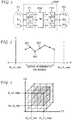
- FIG. 2 illustrates a piece-wise linear curve mapping a color component from value X to Y that may be constructed with pivot points, based on the first 1D LUT (the "pre" set of syntax elements).
- Each pivot point (for example, point 201, 202 or 203) corresponds to a pair of syntax elements (pre_lut_coded_value[ c ][ i ], pre_lut_target_value [ c ][ i ]), and linear interpolation is used to map values between two pivot points.
- pre_lut_coded_value[ c ][ i ] pre_lut_target_value [ c ][ i ]
- th_c1_min is the minimum input value and "th_c1_max” is the maximum input value for color component C1.
- the leftmost pivot point may not be at th_c1_min and the rightmost pivot point may not be at th_c1_max, that is, the piece-wise linear curve may be defined on a subset of the input values.
- the values on which the piece-wise linear curve is defined are referred to as the domain of definition, or the domain, of the piece-wise linear function.
- the color mapping may be defined in the entire color space or a subset of the color space.
- FIG. 3 shows where the input colors are in a subset of color space, where each axis represents a color component of a color space in which a video signal is represented.
- the color space has three color components, C1, C2 and C3, for example, R, G and B, respectively.
- the input colors are defined in the largest cube (the outer cube) [0, th_c1_max] ⁇ [0,th_c2_max] ⁇ [0, th_c3_max].
- the outer cube [0, th_c1_max] ⁇ [0,th_c2_max] ⁇ [0, th_c3_max].
- the CMF is defined in a subset thereof (shaded area [th_c1_min, th_c1_max] ⁇ [th_c2_min, th_c2_max] ⁇ [th_c3_min, th_c3_max]), i.e., the domain of the color mapping function is a subset of the color space ([0, th_c1_max] ⁇ [0, th_c2_max] ⁇ [0, th_c3_max]).
- FIG. 4A illustrates a simplified example in 1D of using a piece-wise linear curve to represent a color mapping function using equal intervals
- FIG. 4B illustrates another example using different intervals, where the dashed line corresponds to a color mapping function to be represented (denoted as "original CMF") and the solid line corresponds to the piece-wise linear curve used to represent/approximate the original CMF.
- original CMF color mapping function to be represented
- each of the "pre" set of syntax elements or the "post” set of syntax elements may support up to 33 pivot points (pre_lut_num_val_minus 1[ c ] and post_lut_num_val_minus1[ c ] are in the range of 0 to 32) in the 1D LUT.
- selection of the pivot points should usually consider the constraints in the number of pivot points available and the quality of the mapped picture. For example, critical colors, such as colors human eyes are more sensitive to, or of greater statistical importance, should usually get finer representation. Generally, for the critical colors, there should be smaller intervals between pivot points in order to provide a more accurate representation.
- pivot points in consideration of statistics and in consideration of the human vision may conflict with each other. For example, we consider an image that includes blue sky (with the values of the B component ranging from 10-63) that corresponds to 95% of the B component and a blue bicycle (with the values of the B component around 56) that correspond to 1% of the B component.
- a piece-wise linear curve based on statistics may choose to have 32 pivot points at values 10-41 (a pivot point at each value of 10-41) and another pivot point at value 63 such that most samples get a good representation.
- To map the blue bicycle the mapping for colors around 56 is interpolated, which may be quite off from the intended mapping. Since the blue bicycle is in the foreground, the distorted blue color in the bike may appear quite pronounced and affect the perceived visual quality.
- the present principles are directed to a method and apparatus for using multiple color mapping functions to improve the representation of the color mapping information.
- Such representation of the color mapping function may be implemented by re-using existing syntax elements.
- the color mapping functions can be decoded and then be applied to process a decoded picture.
- the present principles can also be applied when more rounds of color mappings are used.
- a first color mapping function can be generated, based on, for example, the color mapping information obtained from two different color gradings. Then an input picture is first mapped using the first color mapping function to form Remap 1, for example, one with pivot points at uniform intervals in the domain of definition [0, 1023] in the R component.
- the remapped picture (Remap1) may have color artifacts because some critical colors are not mapped accurately.
- a set of samples may be selected, for example, by an operator manually through a user interface, for further adjustments.
- the CMF creator generates a second color mapping function for the selected samples (in a different domain of definition, for example, 31-62 for R component).
- an operator may select (530) samples that have artifacts and need further adjustment. Then the CMF creator generates (510) a second color mapping function for the selected samples. The second color mapping is applied (540) to the samples from the remapped picture (Remap1), rather than samples from the input picture. An output picture can then be generated (550) based on both color mappings.
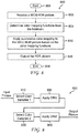
- FIG. 6 illustrates an exemplary method 600 for encoding color mapping information according to the present principles.
- Method 600 starts at step 605.
- it accesses an input picture, for example, a WCG HDR (High Dynamic Range) picture.
- the input picture may also be converted from one color space to another one, for example, from YUV to RGB.
- it determines the first color mapping function, for example, based on the color mapping information from two color gradings.
- the color mapping function should conform to the format required by the bitstream, for example, the format specified by HEVC CRI syntax elements.
- it applies the first color mapping, for example, it transforms the input picture to a mapped picture (Remap1).
- step 640 it determines a second color mapping function, for example, based on samples selected for further adjustment.
- step 650 it applies the second color mapping on the mapped picture (Remap1), for example, it transforms Remap1 to an SDR (Standard Dynamic Range) picture.
- step 660 it encodes the first and second color mapping functions and the input picture into a bitstream.
- step 670 it outputs the bitstream.
- Method 600 ends at step 699.
- color mapping functions can be applied successively and one can encode multiple color mapping functions.
- color mapping functions can be applied successively to process a picture at the decoder side.
- different rules for example, as to how the second color mapping function is applied, can be defined. Which rule is to be used can be signaled in the bitstream or known a priori at both the encoder and decoder side. In the following, we discuss two different rules for successive color mappings in further detail.
- the first color mapping as CRI1
- the first color mapping function as f CRI1
- the second color mapping as CRI2
- the second color mapping function as f CRI2
- Both D CRI1 and D CRI2 can correspond to the entire possible input colors or a subset thereof.
- D CRI1 and D CRI2 are different, for example, D CRI2 may be a subset of D CRI1 , D CRI1 and D CRI2 may overlap, or D CRI1 and D CRI2 may not overlap.
- Function f CRI1 or f CRI2 may be any color mapping function, for example, those we discussed above. Outside the domains of definition of the color mapping functions, an identity function can be used for color mapping (i.e., the input color is not changed after mapping).
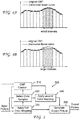
- FIG. 7A shows an exemplary domain of definition for the first color mapping function f CRI1 .
- the possible color values of the input image are now divided into D CRI1 and D CRI1 .
- the range after applying the first color mapping f CRI1 ( D CRI1 ) is shown in FIG. 7B within the dashed line. Samples corresponding to D CRI1 are not changed.
- the domain of the second color mapping function is D CRI2 , which is shown within the solid line in FIG. 7B .
- Remap1 is divided into D CRI2 and Remap1 ⁇ D CRI2 .
- FIG. 7C shows the result of the second color mapping on D CRI2 , i.e., f CRI2 ( D CRI2 ). The samples corresponding to colors in Remap 1 ⁇ D CRI2 are not changed.
- the output can be written as a combination of the mapping results from D CRI2 and Remap 1 ⁇ D CRI2 :
- Remap 2 f CRI 2 D CRI 2 ⁇ Remap 1 ⁇ D CRI 2 .
- the first color mapping CRI1 is applied on its domain of definition, but the second color mapping CRI2 is applied only on samples that have been previously color mapped by CRI1 and which are also inside the domain of definition of function f CRI2 .
- the domain of the second color mapping function is D CRI2 , which is shown within the solid line in FIG. 7B .
- D CRI2 The domain of the second color mapping function
- Remap1 covers D CRI2
- Remap1 ⁇ D CRI2 DCRI2.
- CRI2 is applied only on samples that have been previously color mapped by CRI1 (i.e., samples corresponding to f CRI1 (D CRI1 ) in Remap1) and which are also inside the domain of definition of f CRI1 (D CRI2 ).
- FIG. 7D shows the results of the second color mapping on D CRI2 for samples that have been previously color mapped by CRI1, i.e., f CRI2 ( f CRI1 (D CRI1 ) ⁇ D CRI2 ).
- the samples corresponding to remaining colors i.e., Remap1 ⁇ D CRI2 ⁇ D CRI1
- Remap 2 f CRI 2 f CRI 1 D CRI 1 ⁇ D CRI 2 ⁇ Remap 1 ⁇ D CRI 2 ⁇ D CRI 1 ⁇ .
- Rule 1 can be easier to implement, but affects non-mapped samples (with which the operator may be already satisfied) and may cause new problems.
- Rule 2 only affects mapped samples so the operator has exact control, but it needs to identify which samples are selected so the implementation is more difficult. Based on the user requirements or other inputs, the encoder may choose one rule over the other one.
- color mappings in a subset of the color space.
- the present principles can also be applied to a spatial region of the picture.
- the color mappings can only be applied to a spatial window within the picture.
- additional syntax elements (xmin, ymin) and (xmax, ymax) can be used to indicate the top-left and bottom-right pixel coordinates of the spatial window, respectively.
- additional syntax elements (xmin, ymin) and (xsize, ysize) can be used to indicate the top-left pixel coordinates and the window size in the number of pixels of the spatial window respectively.
- Parameters related to different color mapping functions can be signaled in the bitstream.
- several sets of HEVC CRI are encoded in the bitstream before the video coded picture(s) to which it applies (CRI applies to the reconstructed pictures of the same layer (for example, with the same layer_id) the CRI SEI belongs to), in the order that they are applied.
- the CRI application order is derived from another syntax element such as colour_remap_id.
- the present principles can also be applied to other video compression standard that define parameters for color mapping functions.
- FIG. 8 illustrates an exemplary method 800 for processing a picture based on decoded color mapping information at the receiver side according to the present principles.
- Method 800 starts at step 805.
- receives a WCG HDR picture as input for example, by decoding the WCG HDR picture from a bitstream.
- it determines parameters for two color mapping functions from the bitstream and their order of application for example reconstructing piece-wise linear curves based on the "pre" and "post" sets of HEVC CRI syntax elements and a 3x3 matrix.
- step 830 it performs successive color mappings, for example, it first transforms the WCG HDR picture to a mapped picture using a first color mapping function, and then transforms the mapped picture to an SDR picture using a second color transform function. If the color mapping is performed in a color space different from the color space of input pictures, then the mapped picture should be converted into the color space used for color mapping. At step 840, it outputs the SDR picture. Method 800 ends at step 899.
- FIG. 9 illustrates an exemplary method 900 for performing the first and second mappings according to the present principles, which can be used to implement step 830 in method 800.
- the first color mapping function When the first color mapping function is defined on a domain of definition that is a subset of all possible colors, it selects (910) samples that fall within the domain of the first color mapping function. Then the first mapping function is applied (920) to selected samples, and other samples are not changed. After the first mapping function is applied, a mapped picture (Remap 1) is formed.
- the second color mapping function When the second color mapping function is defined on a domain of definition that is a subset of all possible colors, it selects (930) samples that fall within the domain of the second color mapping function from the mapped picture (Remap1). When the second rule as described in Eq. (5) is used, the samples are selected only if they are previously mapped in the first mapping. The second mapping function is applied (940) to the selected samples in Remap1, and other samples are not changed.
- the present embodiments can use several color mapping functions in order to capture local variations in the pictures. It may be combined with local spatial window to allow the application of the mappings on the samples inside the local spatial window only.
- the successive applications of different color mappings also allow for correcting/improving the first color mapping with the subsequent color mapping, without developing more complex color mapping functions, and thereby reducing the implementation costs.
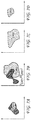
- FIG. 10 illustrates a block diagram of an exemplary system in which various aspects of the exemplary embodiments of the present principles may be implemented.
- System 1000 may be embodied as a device including the various components described below and is configured to perform the processes described above. Examples of such devices, include, but are not limited to, personal computers, laptop computers, smartphones, tablet computers, digital multimedia set top boxes, digital television receivers, personal video recording systems, connected home appliances, and servers.
- System 1000 may be communicatively coupled to other similar systems, and to a display via a communication channel as shown in FIG. 10 and as known by those skilled in the art to implement the exemplary video system described above.
- the system 1000 may include at least one processor 1010 configured to execute instructions loaded therein for implementing the various processes as discussed above.
- Processor 1010 may include embedded memory, input output interface and various other circuitries as known in the art.
- the system 1000 may also include at least one memory 1020 (e.g., a volatile memory device, a non-volatile memory device).
- System 1000 may additionally include a storage device 1040, which may include non-volatile memory, including, but not limited to, EEPROM, ROM, PROM, RAM, DRAM, SRAM, flash, magnetic disk drive, and/or optical disk drive.
- the storage device 1040 may comprise an internal storage device, an attached storage device and/or a network accessible storage device, as non-limiting examples.
- System 1000 may also include an encoder/decoder module 1030 configured to process data to provide an encoded video or decoded video.
- Encoder/decoder module 1030 represents the module(s) that may be included in a device to perform the encoding and/or decoding functions. As is known, a device may include one or both of the encoding and decoding modules. Additionally, encoder/decoder module 1030 may be implemented as a separate element of system 1000 or may be incorporated within processors 1010 as a combination of hardware and software as known to those skilled in the art.
- processors 1010 Program code to be loaded onto processors 1010 to perform the various processes described hereinabove may be stored in storage device 1040 and subsequently loaded onto memory 1020 for execution by processors 1010.
- one or more of the processor(s) 1010, memory 1020, storage device 1040 and encoder/decoder module 1030 may store one or more of the various items during the performance of the processes discussed herein above, including, but not limited to the modulation value, the SDR video, the HDR video, equations, formula, matrices, variables, operations, and operational logic.
- the system 1000 may also include communication interface 1050 that enables communication with other devices via communication channel 1060.
- the communication interface 1050 may include, but is not limited to a transceiver configured to transmit and receive data from communication channel 1060.
- the communication interface may include, but is not limited to, a modem or network card and the communication channel may be implemented within a wired and/or wireless medium.
- the various components of system 1000 may be connected or communicatively coupled together using various suitable connections, including, but not limited to internal buses, wires, and printed circuit boards.
- the exemplary embodiments according to the present principles may be carried out by computer software implemented by the processor 1010 or by hardware, or by a combination of hardware and software.
- the exemplary embodiments according to the present principles may be implemented by one or more integrated circuits.
- the memory 1020 may be of any type appropriate to the technical environment and may be implemented using any appropriate data storage technology, such as optical memory devices, magnetic memory devices, semiconductor-based memory devices, fixed memory and removable memory, as non-limiting examples.
- the processor 1010 may be of any type appropriate to the technical environment, and may encompass one or more of microprocessors, general purpose computers, special purpose computers and processors based on a multi-core architecture, as non-limiting examples.
- the data transmission system 1100 may be, for example, a head-end or transmission system for transmitting a signal using any of a variety of media, such as, satellite, cable, telephone-line, or terrestrial broadcast.
- the data transmission system 1100 also may be used to provide a signal for storage.
- the transmission may be provided over the Internet or some other network.
- the data transmission system 1100 is capable of generating and delivering, for example, video content and other content.
- the data transmission system 1100 receives processed data and other information from a processor 1101.
- the processor 1101 generates color mapping information based on two color gradings of the same video and represents the color information using two color mapping functions, for example, using method 500.
- the processor 1101 may also provide metadata to 1100 indicating, for example, the rule as to how the second color mapping function is applied.
- the data transmission system or apparatus 1100 includes an encoder 1102 and a transmitter 1104 capable of transmitting the encoded signal.
- the encoder 1102 receives data information from the processor 1101.
- the encoder 1102 generates an encoded signal(s).
- the encoder 1102 may include sub-modules, including for example an assembly unit for receiving and assembling various pieces of information into a structured format for storage or transmission.
- the various pieces of information may include, for example, coded or uncoded video, and coded or uncoded elements.
- the encoder 1102 includes the processor 1101 and therefore performs the operations of the processor 1101.
- the transmitter 1104 receives the encoded signal(s) from the encoder 1102 and transmits the encoded signal(s) in one or more output signals.
- the transmitter 1104 may be, for example, adapted to transmit a program signal having one or more bitstreams representing encoded pictures and/or information related thereto.
- Typical transmitters perform functions such as, for example, one or more of providing error-correction coding, interleaving the data in the signal, randomizing the energy in the signal, and modulating the signal onto one or more carriers using a modulator 1106.
- the transmitter 1104 may include, or interface with, an antenna (not shown). Further, implementations of the transmitter 1104 may be limited to the modulator 1106.
- the data transmission system 1100 is also communicatively coupled to a storage unit 1108.
- the storage unit 1108 is coupled to the encoder 1102, and stores an encoded bitstream from the encoder 1102.
- the storage unit 1108 is coupled to the transmitter 1104, and stores a bitstream from the transmitter 1104.
- the bitstream from the transmitter 1104 may include, for example, one or more encoded bitstreams that have been further processed by the transmitter 1104.
- the storage unit 1108 is, in different implementations, one or more of a standard DVD, a Blu-Ray disc, a hard drive, or some other storage device.
- the data receiving system 1200 may be configured to receive signals over a variety of media, such as storage device, satellite, cable, telephone-line, or terrestrial broadcast.
- the signals may be received over the Internet or some other network.
- the data receiving system 1200 may be, for example, a cell-phone, a computer, a set-top box, a television, or other device that receives encoded video and provides, for example, decoded video signal for display (display to a user, for example), for processing, or for storage.
- the data receiving system 1200 may provide its output to, for example, a screen of a television, a computer monitor, a computer (for storage, processing, or display), or some other storage, processing, or display device.
- the data receiving system 1200 is capable of receiving and processing data information.
- the data receiving system or apparatus 1200 includes a receiver 1202 for receiving an encoded signal, such as, for example, the signals described in the implementations of this application.
- the receiver 1202 may receive, for example, a signal providing one or more of a WCG HDR video and color mapping functions, or a signal output from the data transmission system 1100 of FIG. 11 .
- the receiver 1202 may be, for example, adapted to receive a program signal having a plurality of bitstreams representing encoded pictures. Typical receivers perform functions such as, for example, one or more of receiving a modulated and encoded data signal, demodulating the data signal from one or more carriers using a demodulator 1204, de-randomizing the energy in the signal, de-interleaving the data in the signal, and error-correction decoding the signal.
- the receiver 1202 may include, or interface with, an antenna (not shown). Implementations of the receiver 1202 may be limited to the demodulator 1204.
- the data receiving system 1200 includes a decoder 1206.
- the receiver 1202 provides a received signal to the decoder 1206.
- the signal provided to the decoder 1206 by the receiver 1202 may include one or more encoded bitstreams.
- the decoder 1206 outputs a decoded signal, such as, for example, decoded video signals including video information.
- the data receiving system or apparatus 1200 is also communicatively coupled to a storage unit 1207.
- the storage unit 1207 is coupled to the receiver 1202, and the receiver 1202 accesses a bitstream from the storage unit 1207.
- the storage unit 1207 is coupled to the decoder 1206, and the decoder 1206 accesses a bitstream from the storage unit 1207.
- the bitstream accessed from the storage unit 1207 includes, in different implementations, one or more encoded bitstreams.
- the storage unit 1207 is, in different implementations, one or more of a standard DVD, a Blu-Ray disc, a hard drive, or some other storage device.
- the output data from the decoder 1206 is provided, in one implementation, to a processor 1208.
- the processor 1208 is, in one implementation, a processor configured for performing the HDR to SDR mapping based on color mapping information.
- the decoder 1206 includes the processor 1208 and therefore performs the operations of the processor 1208.
- the processor 1208 is part of a downstream device such as, for example, a set-top box or a television.
- the implementations described herein may be implemented in, for example, a method or a process, an apparatus, a software program, a data stream, or a signal. Even if only discussed in the context of a single form of implementation (for example, discussed only as a method), the implementation of features discussed may also be implemented in other forms (for example, an apparatus or program).
- An apparatus may be implemented in, for example, appropriate hardware, software, and firmware.
- the methods may be implemented in, for example, an apparatus such as, for example, a processor, which refers to processing devices in general, including, for example, a computer, a microprocessor, an integrated circuit, or a programmable logic device. Processors also include communication devices, such as, for example, computers, cell phones, portable/personal digital assistants ("PDAs”), and other devices that facilitate communication of information between end-users.
- PDAs portable/personal digital assistants
- the appearances of the phrase “in one embodiment” or “in an embodiment” or “in one implementation” or “in an implementation”, as well any other variations, appearing in various places throughout the specification are not necessarily all referring to the same embodiment.
- Determining the information may include one or more of, for example, estimating the information, calculating the information, predicting the information, or retrieving the information from memory.
- Accessing the information may include one or more of, for example, receiving the information, retrieving the information (for example, from memory), storing the information, processing the information, transmitting the information, moving the information, copying the information, erasing the information, calculating the information, determining the information, predicting the information, or estimating the information.
- Receiving is, as with “accessing”, intended to be a broad term.
- Receiving the information may include one or more of, for example, accessing the information, or retrieving the information (for example, from memory).
- “receiving” is typically involved, in one way or another, during operations such as, for example, storing the information, processing the information, transmitting the information, moving the information, copying the information, erasing the information, calculating the information, determining the information, predicting the information, or estimating the information.
- implementations may produce a variety of signals formatted to carry information that may be, for example, stored or transmitted.
- the information may include, for example, instructions for performing a method, or data produced by one of the described implementations.
- a signal may be formatted to carry the bitstream of a described embodiment.
- Such a signal may be formatted, for example, as an electromagnetic wave (for example, using a radio frequency portion of spectrum) or as a baseband signal.
- the formatting may include, for example, encoding a data stream and modulating a carrier with the encoded data stream.
- the information that the signal carries may be, for example, analog or digital information.
- the signal may be transmitted over a variety of different wired or wireless links, as is known.
- the signal may be stored on a processor-readable medium.
Landscapes
- Engineering & Computer Science (AREA)
- Multimedia (AREA)
- Signal Processing (AREA)
- Compression Or Coding Systems Of Tv Signals (AREA)
- Image Processing (AREA)
- Color Image Communication Systems (AREA)
Claims (15)
- Procédé de traitement d'une image décodée en utilisant des informations de mappage de couleur, comprenant :le décodage (820) d'un premier ensemble de paramètres indicatifs d'une première fonction de mappage de couleur, la première fonction de mappage de couleur étant définie sur un premier sous-ensemble dans un espace de couleur ;le décodage (820) d'un deuxième ensemble de paramètres indicatifs d'une deuxième fonction de mappage de couleur, la deuxième fonction de mappage de couleur étant définie sur un deuxième sous-ensemble dans ledit espace de couleur, dans lequel le deuxième sous-ensemble est différent du premier sous-ensemble dudit espace de couleur ;la sélection d'échantillons (910), dans ladite image décodée, appartenant audit premier sous-ensemble dans ledit espace de couleur pour former un premier ensemble d'échantillons ;l'application (830, 920) de ladite première fonction de mappage de couleur audit premier ensemble d'échantillons dans ladite image décodée pour former une image mappée, dans lequel des échantillons autres que ledit premier ensemble d'échantillons dans ladite image décodée ne sont pas changés par l'application de ladite première fonction de mappage de couleur ;la sélection d'échantillons (930), dans ladite image mappée, appartenant audit deuxième sous-ensemble dans ledit espace de couleur pour former un deuxième ensemble d'échantillons ; etl'application (830, 940) de ladite deuxième fonction de mappage de couleur audit deuxième ensemble d'échantillons pour ajuster des artefacts de couleur dans celle-ci pour former une image de sortie, dans lequel des échantillons autres que ledit deuxième ensemble d'échantillons dans ladite image mappée ne sont pas changés par l'application de ladite deuxième fonction de mappage de couleur.
- Procédé de codage d'informations de mappage de couleur, comprenant :l'accès (620, 640) à une première fonction de mappage de couleur et à une deuxième fonction de mappage de couleur, dans lequel une application successive de la première fonction de mappage de couleur et de la deuxième fonction de mappage de couleur est utilisée pour représenter les informations de mappage de couleur, la première fonction de mappage de couleur étant définie sur un premier sous-ensemble dans un espace de couleur, et ladite deuxième fonction de mappage de couleur étant définie sur un deuxième sous-ensemble dans ledit espace de couleur, dans lequel le deuxième sous-ensemble est différent du premier sous-ensemble dudit espace de couleur,dans lequel des échantillons (910), dans une image, appartenant audit premier sous-ensemble dans ledit espace de couleur sont sélectionnés pour former un premier ensemble d'échantillons,dans lequel ladite première fonction de mappage de couleur est pour l'application (920) audit premier ensemble d'échantillons dans ladite image décodée pour former une image mappée,dans lequel des échantillons (930), dans ladite image mappée, appartenant audit deuxième sous-ensemble dans ledit espace de couleur sont sélectionnés pour former un deuxième ensemble d'échantillons, etdans lequel ladite deuxième fonction de mappage de couleur est pour l'application (940) audit deuxième ensemble d'échantillons pour ajuster des artefacts de couleur dans celle-ci ;le codage (660) d'un premier ensemble de paramètres indicatifs de la première fonction de mappage de couleur ;le codage (660) d'un deuxième ensemble de paramètres indicatifs de la deuxième fonction de mappage de couleur ; etla fourniture (670) d'un flux binaire incluant les premier et deuxième ensembles de paramètres en tant que sortie.
- Procédé selon la revendication 1 ou 2, dans lequel le deuxième sous-ensemble de la deuxième fonction de mappage de couleur est un sous-ensemble du premier sous-ensemble de la première fonction de mappage de couleur.
- Procédé selon la revendication 1, 2 ou 3, dans lequel ladite sélection d'échantillons dans ladite image mappée ne sélectionne que des échantillons qui sont modifiés par ladite application de ladite première fonction de mappage de couleur.
- Procédé selon l'une quelconque des revendications 1 à 4, dans lequel chacune parmi ladite première fonction de mappage de couleur et ladite deuxième fonction de mappage de couleur est représentée par une première fonction linéaire par échelon appliquée à chaque composante de couleur, suivie d'une matrice trois par trois et une deuxième fonction linéaire par échelon appliquée à chaque composante de couleur.
- Procédé selon la revendication 5, dans lequel au moins l'une parmi lesdites première et deuxième fonctions linéaires par échelon utilise des intervalles de points de pivot uniformes.
- Procédé selon la revendication 5 ou 6, dans lequel lesdites première et deuxième fonctions de mappage de couleur sont signalées par un message HEVC CRI SEI.
- Appareil de traitement d'une image décodée en utilisant des informations de mappage de couleur, comprenant au moins une mémoire et un ou plusieurs processeurs, dans lequel lesdits un ou plusieurs processeurs sont configurés pour :décoder un premier ensemble de paramètres indicatifs d'une première fonction de mappage de couleur, la première fonction de mappage de couleur étant définie sur un premier sous-ensemble dans un espace de couleur ;décoder un deuxième ensemble de paramètres indicatifs d'une deuxième fonction de mappage de couleur, la deuxième fonction de mappage de couleur étant définie sur un deuxième sous-ensemble dans ledit espace de couleur, dans lequel le deuxième sous-ensemble est différent du premier sous-ensemble dudit espace de couleur ;sélectionner des échantillons, dans ladite image décodée, appartenant audit premier sous-ensemble dans ledit espace de couleur pour former un premier ensemble d'échantillons ;appliquer ladite première fonction de mappage de couleur audit premier ensemble d'échantillons dans ladite image décodée pour former une image mappée, dans lequel des échantillons autres que ledit premier ensemble d'échantillons dans ladite image décodée ne sont pas changés par l'application de ladite première fonction de mappage de couleur ;sélectionner des échantillons, dans ladite image mappée, appartenant audit deuxième sous-ensemble dans ledit espace de couleur pour former un deuxième ensemble d'échantillons ; etappliquer ladite deuxième fonction de mappage de couleur audit deuxième ensemble d'échantillons pour ajuster des artefacts de couleur dans celle-ci pour former une image de sortie, dans lequel des échantillons autres que ledit deuxième ensemble d'échantillons dans ladite image mappée ne sont pas changés par l'application de ladite deuxième fonction de mappage de couleur.
- Appareil de codage d'informations de mappage de couleur, comprenant au moins une mémoire et un ou plusieurs processeurs, dans lequel lesdits un ou plusieurs processeurs sont configurés pour :accéder à une première fonction de mappage de couleur et à une deuxième fonction de mappage de couleur, dans lequel une application successive de la première fonction de mappage de couleur et de la deuxième fonction de mappage de couleur est utilisée pour représenter les informations de mappage de couleur, la première fonction de mappage de couleur étant définie sur un premier sous-ensemble dans un espace de couleur, et ladite deuxième fonction de mappage de couleur étant définie sur un deuxième sous-ensemble dans ledit espace de couleur, dans lequel le deuxième sous-ensemble est différent du premier sous-ensemble dudit espace de couleur,dans lequel des échantillons, dans une image, appartenant audit premier sous-ensemble dans ledit espace de couleur sont sélectionnés pour former un premier ensemble d'échantillons,dans lequel ladite première fonction de mappage de couleur est pour l'application audit premier ensemble d'échantillons dans ladite image décodée pour former une image mappée, dans lequel des échantillons autres que ledit premier ensemble d'échantillons dans ladite image ne sont pas changés par l'application de ladite première fonction de mappage de couleur ;dans lequel des échantillons, dans ladite image mappée, appartenant audit deuxième sous-ensemble dans ledit espace de couleur sont sélectionnés pour former un deuxième ensemble d'échantillons, etdans lequel ladite deuxième fonction de mappage de couleur est pour l'application audit deuxième ensemble d'échantillons pour ajuster des artefacts de couleur dans celle-ci, dans lequel des échantillons autres que ledit deuxième ensemble d'échantillons dans ladite image mappée ne sont pas changés par l'application de ladite deuxième fonction de mappage de couleur ;coder un premier ensemble de paramètres indicatifs de la première fonction de mappage de couleur ;coder un deuxième ensemble de paramètres indicatifs de la deuxième fonction de mappage de couleur ; etfournir un flux binaire incluant les premier et deuxième ensembles de paramètres en tant que sortie.
- Appareil selon la revendication 8 ou 9, dans lequel le deuxième sous-ensemble de la deuxième fonction de mappage de couleur est un sous-ensemble du premier sous-ensemble de la première fonction de mappage de couleur.
- Appareil selon l'une quelconque des revendications 8 à 10, dans lequel lesdits un ou plusieurs processeurs sont en outre configurés pour :
ne sélectionner que des échantillons, dans ladite image mappée, qui sont modifiés par ladite application de ladite première fonction de mappage de couleur. - Appareil selon l'une quelconque des revendications 8 à 11, dans lequel chacune parmi ladite première fonction de mappage de couleur et ladite deuxième fonction de mappage de couleur est représentée par une première fonction linéaire par échelon appliquée à chaque composante de couleur, suivie d'une matrice trois par trois et une deuxième fonction linéaire par échelon appliquée à chaque composante de couleur.
- Appareil selon la revendication 12, dans lequel au moins l'une parmi lesdites première et deuxième fonctions linéaires par échelon utilise des intervalles de points de pivot uniformes.
- Appareil selon la revendication 12 ou 13, dans lequel lesdites première et deuxième fonctions de mappage de couleur sont signalées par un message HEVC CRI SEI.
- Signal comprenant des informations de mappage de couleur, formaté pour inclure :un premier ensemble de paramètres indicatifs d'une première fonction de mappage de couleur et un deuxième ensemble de paramètres indicatifs d'une deuxième fonction de mappage de couleur, dans lequel une application successive de la première fonction de mappage de couleur et de la deuxième fonction de mappage de couleur est utilisée pour représenter les informations de mappage de couleur, ladite première fonction de mappage de couleur étant définie sur un premier sous-ensemble dans un espace de couleur, et ladite deuxième fonction de mappage de couleur étant définie sur un deuxième sous-ensemble dans ledit espace de couleur, dans lequel le deuxième sous-ensemble est différent du premier sous-ensemble dudit espace de couleur,dans lequel des échantillons, dans une image, appartenant audit premier sous-ensemble dans ledit espace de couleur sont sélectionnés pour former un premier ensemble d'échantillons,dans lequel ladite première fonction de mappage de couleur est pour l'application audit premier ensemble d'échantillons dans ladite image pour former une image mappée, dans lequel des échantillons autres que ledit premier ensemble d'échantillons dans ladite image ne sont pas changés par l'application de ladite première fonction de mappage de couleur, etdans lequel des échantillons, dans ladite image mappée, appartenant audit deuxième sous-ensemble dans ledit espace de couleur sont sélectionnés pour former un deuxième ensemble d'échantillons, pour l'application de ladite deuxième fonction de mappage de couleur pour ajuster des artefacts de couleur dans celle-ci, dans lequel des échantillons autres que ledit deuxième ensemble d'échantillons dans ladite image mappée ne sont pas changés par l'application de ladite deuxième fonction de mappage de couleur.
Applications Claiming Priority (2)
| Application Number | Priority Date | Filing Date | Title |
|---|---|---|---|
| EP15305266.7A EP3059937A1 (fr) | 2015-02-20 | 2015-02-20 | Procédé et appareil permettant de coder des informations de mappage de couleurs et des images de traitement sur la base d'informations de mappage de couleurs |
| PCT/EP2016/053585 WO2016131970A1 (fr) | 2015-02-20 | 2016-02-19 | Procédé et appareil de codage d'informations de transcription de couleurs et traitement d'images basé sur des informations de transcription de couleurs |
Publications (2)
| Publication Number | Publication Date |
|---|---|
| EP3259902A1 EP3259902A1 (fr) | 2017-12-27 |
| EP3259902B1 true EP3259902B1 (fr) | 2021-08-11 |
Family
ID=52727047
Family Applications (2)
| Application Number | Title | Priority Date | Filing Date |
|---|---|---|---|
| EP15305266.7A Withdrawn EP3059937A1 (fr) | 2015-02-20 | 2015-02-20 | Procédé et appareil permettant de coder des informations de mappage de couleurs et des images de traitement sur la base d'informations de mappage de couleurs |
| EP16705530.0A Active EP3259902B1 (fr) | 2015-02-20 | 2016-02-19 | Procédé et appareil permettant de coder des informations de mappage de couleurs et des images de traitement sur la base d'informations de mappage de couleurs |
Family Applications Before (1)
| Application Number | Title | Priority Date | Filing Date |
|---|---|---|---|
| EP15305266.7A Withdrawn EP3059937A1 (fr) | 2015-02-20 | 2015-02-20 | Procédé et appareil permettant de coder des informations de mappage de couleurs et des images de traitement sur la base d'informations de mappage de couleurs |
Country Status (7)
| Country | Link |
|---|---|
| US (1) | US10805506B2 (fr) |
| EP (2) | EP3059937A1 (fr) |
| JP (1) | JP6694439B2 (fr) |
| KR (1) | KR102617121B1 (fr) |
| CN (1) | CN107258082B (fr) |
| TW (1) | TWI692971B (fr) |
| WO (1) | WO2016131970A1 (fr) |
Families Citing this family (13)
| Publication number | Priority date | Publication date | Assignee | Title |
|---|---|---|---|---|
| TWI676389B (zh) * | 2013-07-15 | 2019-11-01 | 美商內數位Vc專利控股股份有限公司 | 至少一種色彩轉換之編碼方法和編碼器、解碼器、顯示裝置、編碼視訊訊號、電腦程式製品及處理器可讀式媒體 |
| US10536695B2 (en) * | 2015-09-09 | 2020-01-14 | Qualcomm Incorporated | Colour remapping information supplemental enhancement information message processing |
| US10397443B2 (en) * | 2016-03-01 | 2019-08-27 | Qualcomm Incorporated | Methods and systems for generating color remapping information supplemental enhancement information messages for video |
| CN116582674A (zh) * | 2016-10-05 | 2023-08-11 | 杜比实验室特许公司 | 与源颜色体积信息的处理相关的方法 |
| EA202191618A3 (ru) * | 2016-11-29 | 2022-01-31 | Долби Лэборетериз Лайсенсинг Корпорейшн | Обмен сообщениями с информацией об исходном цветовом объеме |
| US11252401B2 (en) | 2017-08-07 | 2022-02-15 | Dolby Laboratories Licensing Corporation | Optically communicating display metadata |
| CN113273215A (zh) * | 2019-01-04 | 2021-08-17 | 交互数字Vc控股公司 | 逆映射简化 |
| CN113647111A (zh) * | 2019-03-13 | 2021-11-12 | 交互数字Vc控股公司 | 环内重整形自适应重整形方向 |
| US11146823B2 (en) | 2019-06-25 | 2021-10-12 | Qualcomm Incorporated | Signalling chroma quantization parameter (QP) mapping tables |
| DE102020103437A1 (de) | 2020-02-11 | 2021-08-12 | Schaeffler Technologies AG & Co. KG | Elektrische Antriebseinrichtung und Antriebsanordnung |
| DE102020112510A1 (de) | 2020-05-08 | 2021-11-11 | Schaeffler Technologies AG & Co. KG | Elektrische Antriebseinrichtung und Antriebsanordnung |
| US11606577B2 (en) | 2020-06-09 | 2023-03-14 | Alibaba Group Holding Limited | Method for processing adaptive color transform and low-frequency non-separable transform in video coding |
| CN114692800A (zh) * | 2020-12-29 | 2022-07-01 | 华为技术有限公司 | 一种二维码生成方法以及相关设备 |
Family Cites Families (14)
| Publication number | Priority date | Publication date | Assignee | Title |
|---|---|---|---|---|
| JP3223512B2 (ja) | 1990-12-19 | 2001-10-29 | ソニー株式会社 | 画像表示方法及び装置 |
| US5835099A (en) * | 1996-06-26 | 1998-11-10 | Xerox Corporation | Representing a region of a color image using a space-color separable model |
| JP3960694B2 (ja) | 1998-10-26 | 2007-08-15 | 富士通株式会社 | 色信号変換方法、色信号変換装置、記録媒体、デバイスドライバ及び色変換テーブル |
| NL1013669C2 (nl) | 1999-11-25 | 2001-05-28 | Ocu Technologies B V | Werkwijze en inrichting voor kleurkwantisatie. |
| US7599578B2 (en) * | 2004-09-17 | 2009-10-06 | Nikon Corporation | Apparatus, program, and method for image tone transformation, and electronic camera |
| JP2007013626A (ja) | 2005-06-30 | 2007-01-18 | Canon Inc | 色処理方法および装置 |
| US7573620B2 (en) | 2005-09-01 | 2009-08-11 | Microsoft Corporation | Gamuts and gamut mapping |
| JP2008048314A (ja) * | 2006-08-21 | 2008-02-28 | Fuji Xerox Co Ltd | 画像処理装置、画像処理プログラムおよび画像処理方法 |
| BRPI1009443B1 (pt) * | 2009-03-13 | 2021-08-24 | Dolby Laboratories Licensing Corporation | Método de geração de parâmetros de mapeamento de tons inverso, método de compactação de dados de vídeo e método para geração de um fluxo de bits de saída a partir de um fluxo de bits de entrada |
| JP2011061542A (ja) | 2009-09-10 | 2011-03-24 | Fujifilm Corp | 色情報処理装置、及びそのプログラム |
| TWI538473B (zh) * | 2011-03-15 | 2016-06-11 | 杜比實驗室特許公司 | 影像資料轉換的方法與設備 |
| KR102078335B1 (ko) * | 2013-05-03 | 2020-02-17 | 삼성전자주식회사 | 의료 영상 장치 및 그 제어 방법 |
| TWI676389B (zh) | 2013-07-15 | 2019-11-01 | 美商內數位Vc專利控股股份有限公司 | 至少一種色彩轉換之編碼方法和編碼器、解碼器、顯示裝置、編碼視訊訊號、電腦程式製品及處理器可讀式媒體 |
| JP3223512U (ja) | 2019-06-25 | 2019-10-17 | ロンテック株式会社 | バドミントン用トレーニング器具 |
-
2015
- 2015-02-20 EP EP15305266.7A patent/EP3059937A1/fr not_active Withdrawn
-
2016
- 2016-02-18 TW TW105104806A patent/TWI692971B/zh active
- 2016-02-19 JP JP2017539391A patent/JP6694439B2/ja active Active
- 2016-02-19 KR KR1020177022815A patent/KR102617121B1/ko active IP Right Grant
- 2016-02-19 WO PCT/EP2016/053585 patent/WO2016131970A1/fr active Application Filing
- 2016-02-19 EP EP16705530.0A patent/EP3259902B1/fr active Active
- 2016-02-19 CN CN201680011026.3A patent/CN107258082B/zh active Active
- 2016-02-19 US US15/549,187 patent/US10805506B2/en active Active
Non-Patent Citations (1)
| Title |
|---|
| None * |
Also Published As
| Publication number | Publication date |
|---|---|
| EP3259902A1 (fr) | 2017-12-27 |
| CN107258082B (zh) | 2020-09-29 |
| KR102617121B1 (ko) | 2023-12-26 |
| JP2018512749A (ja) | 2018-05-17 |
| WO2016131970A1 (fr) | 2016-08-25 |
| TW201631970A (zh) | 2016-09-01 |
| US10805506B2 (en) | 2020-10-13 |
| TWI692971B (zh) | 2020-05-01 |
| US20180035015A1 (en) | 2018-02-01 |
| EP3059937A1 (fr) | 2016-08-24 |
| KR20170120108A (ko) | 2017-10-30 |
| JP6694439B2 (ja) | 2020-05-13 |
| CN107258082A (zh) | 2017-10-17 |
Similar Documents
| Publication | Publication Date | Title |
|---|---|---|
| EP3259902B1 (fr) | Procédé et appareil permettant de coder des informations de mappage de couleurs et des images de traitement sur la base d'informations de mappage de couleurs | |
| AU2012394396B2 (en) | Processing high dynamic range images | |
| EP3251084B1 (fr) | Procédé et appareil de codage et de décodage d'une image couleur | |
| US11671550B2 (en) | Method and device for color gamut mapping | |
| EP3430807B1 (fr) | Procédé et dispositif permettant de coder une image à plage dynamique élevée, procédé et dispositif de décodage correspondants | |
| US20180352257A1 (en) | Methods and devices for encoding and decoding a color picture | |
| CN110049327B (zh) | 对色彩变换进行编码的方法和解码的方法以及对应的设备 | |
| US20170188000A1 (en) | Method, apparatus and system for determining a luma value | |
| US11006152B2 (en) | Method and apparatus for encoding/decoding a high dynamic range picture into a coded bitstream | |
| US10019814B2 (en) | Method, apparatus and system for determining a luma value | |
| CN110741623A (zh) | 用于色域映射的方法和设备 | |
| US20190132600A1 (en) | Method and apparatus for encoding/decoding a scalar integer into a parameter representative of a pivot points of a piece-wise linear function | |
| CN107925778B (zh) | 像素预处理和编码 | |
| EP3054417A1 (fr) | Procédé et appareil de codage et de décodage d'images à plage dynamique élevée | |
| WO2016198325A1 (fr) | Procédé et appareil d'encodage vidéo cgs (extensibilité de gamme de couleurs) avec détection d'artéfact | |
| EP3994667A1 (fr) | Traitement d'un nuage de points | |
| EP4300477A1 (fr) | Codage/décodage d'une séquence vidéo associée à des informations de canal alpha | |
| EP3076669A1 (fr) | Procédé et appareil de génération de paramètres de mappage de couleurs pour codage vidéo | |
| EP3528201A1 (fr) | Procédé et dispositif pour régler la saturation dans une image hdr | |
| KR20230107545A (ko) | 채도를 유지하고 색조를 보존하면서 톤 맵퍼 내에서의 크로마 클립핑을 회피하기 위한 방법, 디바이스, 및 장치 | |
| AU2016203467A1 (en) | Method, apparatus and system for determining a luma value |
Legal Events
| Date | Code | Title | Description |
|---|---|---|---|
| STAA | Information on the status of an ep patent application or granted ep patent |
Free format text: STATUS: THE INTERNATIONAL PUBLICATION HAS BEEN MADE |
|
| PUAI | Public reference made under article 153(3) epc to a published international application that has entered the european phase |
Free format text: ORIGINAL CODE: 0009012 |
|
| STAA | Information on the status of an ep patent application or granted ep patent |
Free format text: STATUS: REQUEST FOR EXAMINATION WAS MADE |
|
| 17P | Request for examination filed |
Effective date: 20170724 |
|
| AK | Designated contracting states |
Kind code of ref document: A1 Designated state(s): AL AT BE BG CH CY CZ DE DK EE ES FI FR GB GR HR HU IE IS IT LI LT LU LV MC MK MT NL NO PL PT RO RS SE SI SK SM TR |
|
| AX | Request for extension of the european patent |
Extension state: BA ME |
|
| DAV | Request for validation of the european patent (deleted) | ||
| DAX | Request for extension of the european patent (deleted) | ||
| RAP1 | Party data changed (applicant data changed or rights of an application transferred) |
Owner name: INTERDIGITAL VC HOLDINGS, INC. |
|
| STAA | Information on the status of an ep patent application or granted ep patent |
Free format text: STATUS: EXAMINATION IS IN PROGRESS |
|
| 17Q | First examination report despatched |
Effective date: 20191128 |
|
| RAP1 | Party data changed (applicant data changed or rights of an application transferred) |
Owner name: INTERDIGITAL VC HOLDINGS, INC. |
|
| STAA | Information on the status of an ep patent application or granted ep patent |
Free format text: STATUS: EXAMINATION IS IN PROGRESS |
|
| GRAP | Despatch of communication of intention to grant a patent |
Free format text: ORIGINAL CODE: EPIDOSNIGR1 |
|
| STAA | Information on the status of an ep patent application or granted ep patent |
Free format text: STATUS: GRANT OF PATENT IS INTENDED |
|
| INTG | Intention to grant announced |
Effective date: 20210329 |
|
| GRAS | Grant fee paid |
Free format text: ORIGINAL CODE: EPIDOSNIGR3 |
|
| GRAA | (expected) grant |
Free format text: ORIGINAL CODE: 0009210 |
|
| STAA | Information on the status of an ep patent application or granted ep patent |
Free format text: STATUS: THE PATENT HAS BEEN GRANTED |
|
| AK | Designated contracting states |
Kind code of ref document: B1 Designated state(s): AL AT BE BG CH CY CZ DE DK EE ES FI FR GB GR HR HU IE IS IT LI LT LU LV MC MK MT NL NO PL PT RO RS SE SI SK SM TR |
|
| REG | Reference to a national code |
Ref country code: CH Ref legal event code: EP |
|
| REG | Reference to a national code |
Ref country code: DE Ref legal event code: R096 Ref document number: 602016061941 Country of ref document: DE |
|
| REG | Reference to a national code |
Ref country code: IE Ref legal event code: FG4D Ref country code: AT Ref legal event code: REF Ref document number: 1420585 Country of ref document: AT Kind code of ref document: T Effective date: 20210915 |
|
| REG | Reference to a national code |
Ref country code: NL Ref legal event code: FP |
|
| REG | Reference to a national code |
Ref country code: LT Ref legal event code: MG9D |
|
| REG | Reference to a national code |
Ref country code: AT Ref legal event code: MK05 Ref document number: 1420585 Country of ref document: AT Kind code of ref document: T Effective date: 20210811 |
|
| PG25 | Lapsed in a contracting state [announced via postgrant information from national office to epo] |
Ref country code: RS Free format text: LAPSE BECAUSE OF FAILURE TO SUBMIT A TRANSLATION OF THE DESCRIPTION OR TO PAY THE FEE WITHIN THE PRESCRIBED TIME-LIMIT Effective date: 20210811 Ref country code: SE Free format text: LAPSE BECAUSE OF FAILURE TO SUBMIT A TRANSLATION OF THE DESCRIPTION OR TO PAY THE FEE WITHIN THE PRESCRIBED TIME-LIMIT Effective date: 20210811 Ref country code: LT Free format text: LAPSE BECAUSE OF FAILURE TO SUBMIT A TRANSLATION OF THE DESCRIPTION OR TO PAY THE FEE WITHIN THE PRESCRIBED TIME-LIMIT Effective date: 20210811 Ref country code: BG Free format text: LAPSE BECAUSE OF FAILURE TO SUBMIT A TRANSLATION OF THE DESCRIPTION OR TO PAY THE FEE WITHIN THE PRESCRIBED TIME-LIMIT Effective date: 20211111 Ref country code: AT Free format text: LAPSE BECAUSE OF FAILURE TO SUBMIT A TRANSLATION OF THE DESCRIPTION OR TO PAY THE FEE WITHIN THE PRESCRIBED TIME-LIMIT Effective date: 20210811 Ref country code: HR Free format text: LAPSE BECAUSE OF FAILURE TO SUBMIT A TRANSLATION OF THE DESCRIPTION OR TO PAY THE FEE WITHIN THE PRESCRIBED TIME-LIMIT Effective date: 20210811 Ref country code: ES Free format text: LAPSE BECAUSE OF FAILURE TO SUBMIT A TRANSLATION OF THE DESCRIPTION OR TO PAY THE FEE WITHIN THE PRESCRIBED TIME-LIMIT Effective date: 20210811 Ref country code: FI Free format text: LAPSE BECAUSE OF FAILURE TO SUBMIT A TRANSLATION OF THE DESCRIPTION OR TO PAY THE FEE WITHIN THE PRESCRIBED TIME-LIMIT Effective date: 20210811 Ref country code: NO Free format text: LAPSE BECAUSE OF FAILURE TO SUBMIT A TRANSLATION OF THE DESCRIPTION OR TO PAY THE FEE WITHIN THE PRESCRIBED TIME-LIMIT Effective date: 20211111 Ref country code: PT Free format text: LAPSE BECAUSE OF FAILURE TO SUBMIT A TRANSLATION OF THE DESCRIPTION OR TO PAY THE FEE WITHIN THE PRESCRIBED TIME-LIMIT Effective date: 20211213 |
|
| PG25 | Lapsed in a contracting state [announced via postgrant information from national office to epo] |
Ref country code: PL Free format text: LAPSE BECAUSE OF FAILURE TO SUBMIT A TRANSLATION OF THE DESCRIPTION OR TO PAY THE FEE WITHIN THE PRESCRIBED TIME-LIMIT Effective date: 20210811 Ref country code: LV Free format text: LAPSE BECAUSE OF FAILURE TO SUBMIT A TRANSLATION OF THE DESCRIPTION OR TO PAY THE FEE WITHIN THE PRESCRIBED TIME-LIMIT Effective date: 20210811 Ref country code: GR Free format text: LAPSE BECAUSE OF FAILURE TO SUBMIT A TRANSLATION OF THE DESCRIPTION OR TO PAY THE FEE WITHIN THE PRESCRIBED TIME-LIMIT Effective date: 20211112 |
|
| PG25 | Lapsed in a contracting state [announced via postgrant information from national office to epo] |
Ref country code: DK Free format text: LAPSE BECAUSE OF FAILURE TO SUBMIT A TRANSLATION OF THE DESCRIPTION OR TO PAY THE FEE WITHIN THE PRESCRIBED TIME-LIMIT Effective date: 20210811 |
|
| REG | Reference to a national code |
Ref country code: DE Ref legal event code: R097 Ref document number: 602016061941 Country of ref document: DE |
|
| PG25 | Lapsed in a contracting state [announced via postgrant information from national office to epo] |
Ref country code: SM Free format text: LAPSE BECAUSE OF FAILURE TO SUBMIT A TRANSLATION OF THE DESCRIPTION OR TO PAY THE FEE WITHIN THE PRESCRIBED TIME-LIMIT Effective date: 20210811 Ref country code: SK Free format text: LAPSE BECAUSE OF FAILURE TO SUBMIT A TRANSLATION OF THE DESCRIPTION OR TO PAY THE FEE WITHIN THE PRESCRIBED TIME-LIMIT Effective date: 20210811 Ref country code: RO Free format text: LAPSE BECAUSE OF FAILURE TO SUBMIT A TRANSLATION OF THE DESCRIPTION OR TO PAY THE FEE WITHIN THE PRESCRIBED TIME-LIMIT Effective date: 20210811 Ref country code: EE Free format text: LAPSE BECAUSE OF FAILURE TO SUBMIT A TRANSLATION OF THE DESCRIPTION OR TO PAY THE FEE WITHIN THE PRESCRIBED TIME-LIMIT Effective date: 20210811 Ref country code: CZ Free format text: LAPSE BECAUSE OF FAILURE TO SUBMIT A TRANSLATION OF THE DESCRIPTION OR TO PAY THE FEE WITHIN THE PRESCRIBED TIME-LIMIT Effective date: 20210811 Ref country code: AL Free format text: LAPSE BECAUSE OF FAILURE TO SUBMIT A TRANSLATION OF THE DESCRIPTION OR TO PAY THE FEE WITHIN THE PRESCRIBED TIME-LIMIT Effective date: 20210811 |
|
| PLBE | No opposition filed within time limit |
Free format text: ORIGINAL CODE: 0009261 |
|
| STAA | Information on the status of an ep patent application or granted ep patent |
Free format text: STATUS: NO OPPOSITION FILED WITHIN TIME LIMIT |
|
| 26N | No opposition filed |
Effective date: 20220512 |
|
| PG25 | Lapsed in a contracting state [announced via postgrant information from national office to epo] |
Ref country code: IT Free format text: LAPSE BECAUSE OF FAILURE TO SUBMIT A TRANSLATION OF THE DESCRIPTION OR TO PAY THE FEE WITHIN THE PRESCRIBED TIME-LIMIT Effective date: 20210811 |
|
| PG25 | Lapsed in a contracting state [announced via postgrant information from national office to epo] |
Ref country code: SI Free format text: LAPSE BECAUSE OF FAILURE TO SUBMIT A TRANSLATION OF THE DESCRIPTION OR TO PAY THE FEE WITHIN THE PRESCRIBED TIME-LIMIT Effective date: 20210811 |
|
| PG25 | Lapsed in a contracting state [announced via postgrant information from national office to epo] |
Ref country code: MC Free format text: LAPSE BECAUSE OF FAILURE TO SUBMIT A TRANSLATION OF THE DESCRIPTION OR TO PAY THE FEE WITHIN THE PRESCRIBED TIME-LIMIT Effective date: 20210811 |
|
| REG | Reference to a national code |
Ref country code: CH Ref legal event code: PL |
|
| REG | Reference to a national code |
Ref country code: BE Ref legal event code: MM Effective date: 20220228 |
|
| PG25 | Lapsed in a contracting state [announced via postgrant information from national office to epo] |
Ref country code: LU Free format text: LAPSE BECAUSE OF NON-PAYMENT OF DUE FEES Effective date: 20220219 |
|
| PG25 | Lapsed in a contracting state [announced via postgrant information from national office to epo] |
Ref country code: LI Free format text: LAPSE BECAUSE OF NON-PAYMENT OF DUE FEES Effective date: 20220228 Ref country code: IE Free format text: LAPSE BECAUSE OF NON-PAYMENT OF DUE FEES Effective date: 20220219 Ref country code: CH Free format text: LAPSE BECAUSE OF NON-PAYMENT OF DUE FEES Effective date: 20220228 |
|
| PG25 | Lapsed in a contracting state [announced via postgrant information from national office to epo] |
Ref country code: BE Free format text: LAPSE BECAUSE OF NON-PAYMENT OF DUE FEES Effective date: 20220228 |
|
| PGFP | Annual fee paid to national office [announced via postgrant information from national office to epo] |
Ref country code: FR Payment date: 20230223 Year of fee payment: 8 |
|
| P01 | Opt-out of the competence of the unified patent court (upc) registered |
Effective date: 20230514 |
|
| PG25 | Lapsed in a contracting state [announced via postgrant information from national office to epo] |
Ref country code: HU Free format text: LAPSE BECAUSE OF FAILURE TO SUBMIT A TRANSLATION OF THE DESCRIPTION OR TO PAY THE FEE WITHIN THE PRESCRIBED TIME-LIMIT; INVALID AB INITIO Effective date: 20160219 |
|
| PGFP | Annual fee paid to national office [announced via postgrant information from national office to epo] |
Ref country code: NL Payment date: 20240226 Year of fee payment: 9 |
|
| PG25 | Lapsed in a contracting state [announced via postgrant information from national office to epo] |
Ref country code: MK Free format text: LAPSE BECAUSE OF FAILURE TO SUBMIT A TRANSLATION OF THE DESCRIPTION OR TO PAY THE FEE WITHIN THE PRESCRIBED TIME-LIMIT Effective date: 20210811 Ref country code: CY Free format text: LAPSE BECAUSE OF FAILURE TO SUBMIT A TRANSLATION OF THE DESCRIPTION OR TO PAY THE FEE WITHIN THE PRESCRIBED TIME-LIMIT Effective date: 20210811 |
|
| PGFP | Annual fee paid to national office [announced via postgrant information from national office to epo] |
Ref country code: DE Payment date: 20240228 Year of fee payment: 9 Ref country code: GB Payment date: 20240220 Year of fee payment: 9 |