EP3258869B1 - Cryoneedle - Google Patents
Cryoneedle Download PDFInfo
- Publication number
- EP3258869B1 EP3258869B1 EP16708281.7A EP16708281A EP3258869B1 EP 3258869 B1 EP3258869 B1 EP 3258869B1 EP 16708281 A EP16708281 A EP 16708281A EP 3258869 B1 EP3258869 B1 EP 3258869B1
- Authority
- EP
- European Patent Office
- Prior art keywords
- cryoneedle
- outer tube
- heat exchange
- cryogas
- supply line
- Prior art date
- Legal status (The legal status is an assumption and is not a legal conclusion. Google has not performed a legal analysis and makes no representation as to the accuracy of the status listed.)
- Active
Links
Images




Classifications
-
- A—HUMAN NECESSITIES
- A61—MEDICAL OR VETERINARY SCIENCE; HYGIENE
- A61B—DIAGNOSIS; SURGERY; IDENTIFICATION
- A61B18/00—Surgical instruments, devices or methods for transferring non-mechanical forms of energy to or from the body
- A61B18/02—Surgical instruments, devices or methods for transferring non-mechanical forms of energy to or from the body by cooling, e.g. cryogenic techniques
-
- A—HUMAN NECESSITIES
- A61—MEDICAL OR VETERINARY SCIENCE; HYGIENE
- A61B—DIAGNOSIS; SURGERY; IDENTIFICATION
- A61B18/00—Surgical instruments, devices or methods for transferring non-mechanical forms of energy to or from the body
- A61B2018/00005—Cooling or heating of the probe or tissue immediately surrounding the probe
- A61B2018/00011—Cooling or heating of the probe or tissue immediately surrounding the probe with fluids
- A61B2018/00017—Cooling or heating of the probe or tissue immediately surrounding the probe with fluids with gas
-
- A—HUMAN NECESSITIES
- A61—MEDICAL OR VETERINARY SCIENCE; HYGIENE
- A61B—DIAGNOSIS; SURGERY; IDENTIFICATION
- A61B18/00—Surgical instruments, devices or methods for transferring non-mechanical forms of energy to or from the body
- A61B2018/00005—Cooling or heating of the probe or tissue immediately surrounding the probe
- A61B2018/00041—Heating, e.g. defrosting
-
- A—HUMAN NECESSITIES
- A61—MEDICAL OR VETERINARY SCIENCE; HYGIENE
- A61B—DIAGNOSIS; SURGERY; IDENTIFICATION
- A61B18/00—Surgical instruments, devices or methods for transferring non-mechanical forms of energy to or from the body
- A61B18/02—Surgical instruments, devices or methods for transferring non-mechanical forms of energy to or from the body by cooling, e.g. cryogenic techniques
- A61B2018/0231—Characteristics of handpieces or probes
- A61B2018/0262—Characteristics of handpieces or probes using a circulating cryogenic fluid
-
- A—HUMAN NECESSITIES
- A61—MEDICAL OR VETERINARY SCIENCE; HYGIENE
- A61B—DIAGNOSIS; SURGERY; IDENTIFICATION
- A61B18/00—Surgical instruments, devices or methods for transferring non-mechanical forms of energy to or from the body
- A61B18/02—Surgical instruments, devices or methods for transferring non-mechanical forms of energy to or from the body by cooling, e.g. cryogenic techniques
- A61B2018/0231—Characteristics of handpieces or probes
- A61B2018/0262—Characteristics of handpieces or probes using a circulating cryogenic fluid
- A61B2018/0268—Characteristics of handpieces or probes using a circulating cryogenic fluid with restriction of flow
-
- A—HUMAN NECESSITIES
- A61—MEDICAL OR VETERINARY SCIENCE; HYGIENE
- A61B—DIAGNOSIS; SURGERY; IDENTIFICATION
- A61B18/00—Surgical instruments, devices or methods for transferring non-mechanical forms of energy to or from the body
- A61B18/02—Surgical instruments, devices or methods for transferring non-mechanical forms of energy to or from the body by cooling, e.g. cryogenic techniques
- A61B2018/0231—Characteristics of handpieces or probes
- A61B2018/0262—Characteristics of handpieces or probes using a circulating cryogenic fluid
- A61B2018/0268—Characteristics of handpieces or probes using a circulating cryogenic fluid with restriction of flow
- A61B2018/0281—Characteristics of handpieces or probes using a circulating cryogenic fluid with restriction of flow using a tortuous path, e.g. formed by fins or ribs
-
- A—HUMAN NECESSITIES
- A61—MEDICAL OR VETERINARY SCIENCE; HYGIENE
- A61B—DIAGNOSIS; SURGERY; IDENTIFICATION
- A61B18/00—Surgical instruments, devices or methods for transferring non-mechanical forms of energy to or from the body
- A61B18/02—Surgical instruments, devices or methods for transferring non-mechanical forms of energy to or from the body by cooling, e.g. cryogenic techniques
- A61B2018/0231—Characteristics of handpieces or probes
- A61B2018/0262—Characteristics of handpieces or probes using a circulating cryogenic fluid
- A61B2018/0268—Characteristics of handpieces or probes using a circulating cryogenic fluid with restriction of flow
- A61B2018/0281—Characteristics of handpieces or probes using a circulating cryogenic fluid with restriction of flow using a tortuous path, e.g. formed by fins or ribs
- A61B2018/0287—Characteristics of handpieces or probes using a circulating cryogenic fluid with restriction of flow using a tortuous path, e.g. formed by fins or ribs the fluid flowing through a long thin tube with spiral shape
-
- A—HUMAN NECESSITIES
- A61—MEDICAL OR VETERINARY SCIENCE; HYGIENE
- A61B—DIAGNOSIS; SURGERY; IDENTIFICATION
- A61B18/00—Surgical instruments, devices or methods for transferring non-mechanical forms of energy to or from the body
- A61B18/02—Surgical instruments, devices or methods for transferring non-mechanical forms of energy to or from the body by cooling, e.g. cryogenic techniques
- A61B2018/0293—Surgical instruments, devices or methods for transferring non-mechanical forms of energy to or from the body by cooling, e.g. cryogenic techniques using an instrument interstitially inserted into the body, e.g. needle
Definitions
- This disclosure generally relates to a cryoneedle for forming iceballs having symmetric shapes.
- Cryosurgical systems comprise one or more cryoneedle connected to one or more cryogas sources. Such systems are described in the commonly-assigned patent, U.S. Pat. No. 8,066,697 and in published application, U.S. Pub. No. 2010/0256620 A1 .
- a cryogas can be delivered from a cryogas source to one or more cryoneedles.
- the cryoneedle can be cooled or heated due to expansion of the cryogas, thereby freezing or thawing tissue in the vicinity of the cryoneedle.
- Cryoneedles and cryosurgical systems are also disclosed in US 2007/0149959 , WO 2005/000106 , US 2012/0065630 , US 6270476 , WO2014/144626 , and US 2006/0122590 .
- the invention provides a cryoneedle comprising an outer tube having a distal section placed at or near a target area of a patient's anatomy and a longitudinal axis; a gas supply line positioned within the outer tube, the gas supply line configured to supply a cryogas for forming an ice ball on an outer surface of the outer tube over the distal section; an expansion chamber located within the distal section such that the gas supply line terminates in the expansion chamber; a return gas flow lumen defined annularly between the heat exchange helix and the gas supply line adapted to carry cryogas from the expansion chamber along a return flow path; an electrical resistance heater positioned coaxially with the gas supply line and the outer tube to facilitate heating of the distal section of the cryoneedle; characterised in that the cryoneedle further comprises a heat exchange helix contacting the inner surface of the outer tube; the electrical resistance heater comprises metal wires wound in helical coils around and in contact with an outer surface of the gas supply line; and the coils of the heat exchange helix are in
- the heat exchange helix has an increasing surface area per unit distance of the distal section such that the iceball has a generally symmetric shape.
- the return gas lumen provides a helical return path for the cryogas from the expansion chamber toward the proximal section.
- a method of forming symmetric iceballs during cryosurgery can comprise providing a cryosurgery system comprising a cryoneedle such as those described herein.
- the method involves supplying a cryogas through the gas supply line, expanding the cryogas at the expansion chamber, providing a helical return path for cryogas in the distal section, wherein the cryogas flows in the return gas flow lumen in a direction from the expansion chamber toward a proximal section, and forming an iceball on an outer surface of the outer tube over the distal section such that the iceball has a generally symmetric shape.
- Cryosurgical systems can be used for cryoablating target tissues (e.g., a tumor).
- target tissues e.g., a tumor
- cryosurgical systems include one or more cryoneedles, one or more cryogas sources and a controller.
- the cryogas sources can supply gases such as argon, nitrogen, air, krypton, C02, CF4, xenon, and various other gases.
- the cryosurgical system can also include a controller having one or more sensors, flow meters, timers, analog/digital converters, wired or wireless communication modules, etc. Additionally, the controller can also regulate the flow rate, temperature and pressure of cryogas supplied to the cryoneedle.
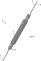
- cryoneedle 10 may deploy one or more cryoneedles such as those illustrated in Fig. 1 to cryoablate a target area of a patient anatomy by placing the cryoneedle 10 at or near the target area of the patient anatomy.
- cryoneedle 10 utilizes the Joule-Thomson effect to produce cooling or heating.
- a cryogas expands in the cryoneedle 10 from a higher pressure to a lower pressure. Expansion of the cryogas results in temperatures at or below those necessary for cryoablating a tissue in the vicinity of the tip of the cryoneedle 10. Heat transfer between the expanded cryogas and the outer walls of the cryoneedle 10 can be used to form an iceball, and consequently cryoablate the tissue.
- components of the cryoneedle 10 are located within an outer tube 12 (e.g., a trocar).
- the outer tube 12 can have a distal operating head 16 disposed at a distal section 20 of the cryoneedle 10 for penetrating through tissues of a patient during deployment.
- the outer tube 12 can be of substantially thin cross section for allowing deployment in tissues of a patient.
- the outer tube 12 has an outer diameter of about 2.1 millimeters. Other dimensions of the outer tube 12 are also contemplated.
- the outer tube 12 can have an outer diameter of between about 1.5 millimeters and about 2.4 millimeters.
- the outer tube 12 can have a distal section 20 placed at or near a target area of a patient's anatomy.
- the outer tube 12 can also have a middle section 24 positioned between the distal section 20, and a proximal section 30 of the cryoneedle 10. Additionally, the outer tube 12 has a longitudinal axis 34.
- the cryoneedle 10 includes a gas supply line 38 extending substantially along its length for providing a high-pressure gas to the distal operating head 16.
- the gas supply line 38 can be positioned coaxially/concentrically within the outer tube 12.
- the gas supply line 38 can be configured to supply a cryogas for forming iceballs on an outer surface 40 of the outer tube 12 over the distal section 20.
- the gas supply line 38 can be a capillary tube.
- the gas supply line 38 comprises a proximal heat exchanger 50 positioned in the proximal section 30 of the cryoneedle 10 and operably connected to a cryogas source (not shown) at a first end 52 and the capillary tube at a second end 54.
- the proximal heat exchanger 50 can precool the cryogas from the cryogas source prior to being delivered to the middle and/or distal sections.
- the proximal heat exchanger 50 can be a hollow helical tube 56 wound around a central core 58.
- the helical tube 56 of the proximal heat exchanger 50 provides increased heat exchange surface area per unit length of the helical tube 56 in comparison to heat exchangers that are not coiled.
- the helical tube 56 can be made of brass. Other metals such as stainless steel are also contemplated.
- the proximal heat exchanger 50 is positioned far from the distal operating head 16. For instance, the proximal heat exchanger 50 can be positioned at a handle (not shown).
- an insulating outer cover (not shown) can be positioned over the proximal heat exchanger 50 so as to facilitate manual deployment (e.g., by grasping the handle) by an operator (e.g., a surgeon).
- the insulating outer cover can be made of heat shrink plastic film.
- the central core 58 can be substantially rigid in comparison to the distal operating head 16. Such embodiments can be beneficial in providing a cryoneedle 10 with a substantially flexible distal operating head 16 for penetrating soft tissue and a substantially rigid handle having a proximal heat exchanger 50 to precool the cryogas.
- the distal section 20 can have a first portion 60 and a second portion 70.
- the cryoneedle 10 includes an expansion chamber 72 within the first portion 60 of the distal section 20 such that the gas supply line 38 terminates in the expansion chamber 72.
- the gas supply line 38 e.g., capillary tube
- the Joule-Thomson orifice 74 can be positioned near the expansion chamber 72.
- a high-pressure cryogas supplied via the gas supply line 38 exits gas supply line 38 via the Joule-Thomson orifice 74 and expands in the expansion chamber 72.
- cryogas As the cryogas expands in the expansion chamber 72, it cools rapidly and forms iceballs of different shapes and/or sizes over the outer surface 40 of the outer tube 12.
- the expansion of the cryogas can be such that when expanded, the cryogas is colder than the incoming cryogas.
- the cryoneedle 10 comprises a return gas flow lumen 78 defined annularly between the heat exchange helix 100 and the central gas supply line 38.
- the return gas flow lumen 78 can carry cryogas from the expansion chamber 72 toward the proximal section 30 of the cryoneedle 10 along a return flow path 79 shown in Fig. 2 .
- the return gas flow lumen 78 is defined along a return path of the cryogas between the gas supply line 38 and the inner wall 102 of the outer tube 12 of the cryoneedle 10.
- the return gas flow lumen 78 is helical in shape. Referring now to Figs.
- the cryogas expands in the expansion chamber 72, and the expanded cryogas flows in the return flow lumen, thereby cooling incoming cryogas flowing through the gas supply line 38.
- the expanded gas can subsequently be exhausted to the atmosphere near an end of the outer tube 12.
- a heater 80 c is provided within the outer tube 12 near the distal section 20 to facilitate disengagement of cryoneedle 10 after cryoablating a tissue, for thawing a tissue at or near the distal section 20 of the cryoneedle 10, for cauterizing tissues, or for other purposes.
- an electrical heater 80 is provided coaxially with the gas supply line 38 and the outer tube 12 to facilitate heating the distal section 20 of the cryoneedle 10.
- the electrical heater 80 is a resistive heater, wherein the electrical heater 80 generates heat proportional to the current flow therethrough and the electrical resistance of electrical heater 80.
- the controller can supply and/or regulate (e.g., with a Wheatstone bridge, ampere meter or voltmeter) electrical current flow to the electrical heater 80 within the cryoneedle 10.
- the electrical heater 80 comprises metal wires (e.g., copper) wound in helical coils (e.g., between about 50 coils and about 200 coils) around the gas supply tube.
- the wires are wound with a negligible pitch between adj acent coils of the wire.
- the wires contact an outer surface 40 of the gas supply tube.
- the temperature of the cryogas can be colder in the first portion 60 of the distal section 20 (due to Joule-Thomson effect), than in the second portion 70, and heat transfer between the cryogas and the outer tube 12 can be higher over the first portion 60 than in the second portion 70.
- This can result in an iceball having an asymmetric shape (e.g., pear-shaped with the iceball generally tapering toward the second portion 70).
- the cryoneedle 10 includes a heat exchange helix 100, comprising coils configured for enhancing heat exchange between the cryogas and the outer tube 12.
- the heat exchange helix 100 contacts the inner wall 102 of the outer tube 12 and is positioned coaxially with the outer tube 12. As perhaps best seen in Fig. 2 , the coils of the heat exchange helix 100 are in contact with the inner wall 102 of the outer tube 12 and do not contact the heater 80 or the gas supply line 38 (e.g., capillary tube). These coils effectively act as fins on the inner wall 102 of the outer tube 12 and improve heat transfer to the outer tube 12 to form iceballs having symmetric shapes wherein the symmetry is about the longitudinal axis 34 of the outer tube 12.
- the presence of heat exchange helix 100 on the inner wall 102 of the outer tube 12 increases the surface area over which return gas flows over from the expansion chamber 72 and toward the proximal section 30 of the cryoneedle 10.
- the cryogas flows along a helical path from the expansion chamber 72 toward the proximal section 30 of the cryoneedle 10 resulting in enhanced heat exchange.
- Such embodiments result in higher heat transfer between the expanded cryogas and the outer tube 12, consequently providing a desired iceball shape and size (e.g., a symmetric shape such as sphere or ellipsoid) as will be described below.
- the heat exchange helix 100 enhances heat transfer over the distal section 20 by increasing surface area over which heat transfer occurs from the cryogas to the outer tube 12 of the cryoneedle 10.
- the heat exchange helix 100 provides a heat exchange surface area at the distal section 20 and permits heat transfer between the cryogas and the outer tube 12 such that the outer tube 12 is evenly cooled to a temperature of about -150 degree Celsius when the cryogas temperature is about -155 degree Celsius.
- Other temperatures are also contemplated.
- the outer tube 12 can be cooled to any temperature in the range of between about -145 degree Celsius and about -150 degree Celsius, when the cryogas temperature is between about -155 degree Celsius and about - 150 degree Celsius.
- the heat exchange helix 100 can provide generally uniform cooling over the entire length 104 of the distal section 20 such that the iceball (best illustrated in Figs. 7A and 7B ) is generally symmetric in shape.
- the heat exchange helix 100 can facilitate cooling the outer tube 12 evenly over the entire length 104 of the distal section 20 such that the heat transfer rate between the cryogas and the outer tube 12 is approximately constant over the entire length 104 of the distal section 20.
- the cryogas flowing in the return flow lumen over the first portion 60 can be at a lower temperature than the cryogas flowing in the return flow lumen over the second portion 70 because of rapid expansion of the cryogas near the Joule Thomson orifice and associate rapid cooling that occurs at the first portion 60.
- the heat exchange helix 100 can increase heat transfer between cryogas and the outer tube 12 over the second portion 70 such that the heat transfer rate between the cryogas and the outer tube 12 over the first portion 60 roughly equals the heat transfer rate between the cryogas and the outer tube 12 over the second portion 70.
- Such embodiments can facilitate in generating iceballs having symmetric shape, and prevent formation of iceballs having asymmetric shapes (e.g., pear-shaped).
- the heat exchange helix 100 has a helix pitch.
- the helix pitch can be configured to generate an iceball 150 having a symmetrical shape (e.g., ellipsoidal or spherical).
- the coils can have variable helix pitch.
- two helix pitches are shown: a first pitch 108 over the first portion 60 of the distal section 20 and a second pitch 110 over the second portion 70 of the distal section 20.
- the first pitch 108 can be greater than the second pitch 110 such that adjacent coils of the heat exchange helix 100 are spaced further apart in the first portion 60 than in the second portion 70.
- the heat exchange helix 100 can have fewer coils per unit length in the first portion 60 than in the second portion 70.
- the heat exchange helix 100 has a higher surface area per unit length in the second portion 70 of the distal section 20 in comparison to the surface area per unit length in the first portion 60 of the distal section 20.
- the cryogas has a higher temperature in the second portion 70 than in the first portion 60
- the increased surface area in the second portion 70 facilitates heat transfer rates between the cryogas and the outer tube 12 that is roughly equal so that the iceball 150 (best illustrated in Figs. 7A and 7B ) has a generally symmetric shape.
- the helix pitch can be constant over the entire length 104 of the distal section 20.
- the heat exchange helix 100 is a coiled spring.
- the heat exchange helix 100 can be made of tin coated copper.
- Other metals and alloys e.g., stainless steel
- having sufficient resiliency and/or malleability so as to be formed into a helical shape of desired helix pitch are also contemplated.
- the cryoneedle 10 comprises an insulating sheath 120 positionable at locations other than the distal section 20.
- the insulating sheath 120 abuts against the outer tube 12 to prevent the expanded cryogas returning from the expansion chamber 72 from coming into contact with the outer tube 12.
- the cold return gas avoids contact with areas of the patient's body other than intended the target area such that an iceball 150 is therefore formed in the exposed region of the outer tube 12 (e.g., regions of the outer tube 12 not having the insulating sheath 120 positioned between the outer tube 12 and the return gas flow lumen 78).
- regions of the outer tube 12 not having the insulating sheath 120 positioned between the outer tube 12 and the return gas flow lumen 78 are examples of the outer tube 12 positioned between the outer tube 12 and the return gas flow lumen 78.
- the entire length 104 of the distal section 20 is exposed. Over this exposed region length 140, the expanded cryogas contacts the outer tube 12 of the cryoneedle 10 and forms an iceball 150.
- the insulated sheath is positioned over the entire length of the middle section 24 of the cryoneedle 10 in this embodiment. Over the entire length of the middle section 24, the cryogas is prevented from contacting the outer tube 12, thereby preventing cooling of tissue surrounding the middle section 24 and/or iceball formation thereon.
- the exposed region length 140 (best seen in Fig. 2 ) of the outer tube 12 can determine the shape of the iceball.
- Figs. 7A and 7B for instance illustrate an ellipsoidal and a spherical iceball 150 formed over the distal section 20 of the cryoneedle 10, respectively.
- the iceball 150 can have a substantially ellipsoidal shape such as that illustrated in Fig. 7A .
- the iceball 150 can have a substantially spherical shape such as that illustrated in Fig. 7B . While in both Figs.
- the iceball 150 formed is of a symmetric shape
- the exposed region length 140 of the outer tube 12 influences the aspect ratio 160 of the iceball 150 shape.
- a shorter exposed region length produces a spherical iceball 150 and a longer exposed region length produces an ellipsoidal iceball.
- various symmetric shapes can be obtained.
- the exposed region length 140 can thus be varied to change an aspect ratio 160 of the iceball 150. As illustrated in Figs.
- aspect ratio 160 of the iceball 150 can be defined as the ratio of length 162 of the iceball 150 measured along the lengthwise direction of the cryoneedle 10 and the width 164 of the iceball 150 measured in a direction perpendicular to the lengthwise direction of the cryoneedle 10. As illustrated, an aspect ratio 160 of about one implies a spherical iceball 150.
- the heat exchange helix 100 disclosed herein can create additional resistance to flow of expanded cryogas in the return gas flow lumen 78.
- the dimensions of the cryoneedle 10 can be configured to prevent excessive flow resistance and/or back pressure being generated in the cryoneedle 10.
- the insulating sheath 120 can have dimensions suitable to permit the return flow of expanded cryogas from the distal section 20 toward the proximal section 30.
- the insulating sheath 120 can have an inner diameter 170 sufficient to create an annular gap between the gas supply line 38 and an outer wall of the insulating sheath 120 as best seen in Figs 5 and 6 .
- the inner diameter 170 of the insulating sheath 120 is about 1.32 mm. In other examples, the insulating sheath 120 can have an inner diameter 170 between about 0.5 millimeters and about 2 millimeters. In one example, when the outer diameter of the outer tube 12 is about 2.1 millimeters, the insulating sheath 120 can have an inner diameter 170 of between about 1.0 millimeter and about 1.4 millimeters. In another example, when the outer diameter of the outer tube 12 is about 1.5 millimeters, the insulating sheath 120 can have an inner diameter 170 of about 0.72 millimeters.
- the insulating sheath 120 can have an inner diameter 170 of between about 1.25 millimeters and about 1.7 millimeters.
- the inner diameter 170 of the insulating sheath 120 can therefore be sufficiently large to minimize back pressure acting on the expanded cryogas flowing through the annular gap from the return gas flow lumen 78. In such cases, backpressure is minimized to allow the pressure of the expanding cryogas to fall as low as possible (e.g., zero gauge), which results in a lower gas temperature and bigger iceball. Maximizing the inner diameter 170 of the insulating sheath 120 helps to minimize the overall backpressure of the cryoneedle 10.
- a method of forming ice balls having a symmetric shape during cryosurgery can comprise the step of providing a cryosurgery system such as those disclosed herein, supplying a cryogas through the gas supply line 38, expanding the cryogas in the expansion chamber 72, providing a helical return path for cryogas in the distal section 20, the cryogas flowing in the return gas flow lumen 78 in a direction from the expansion chamber 72 toward a proximal section 30, and forming an iceball 150 on an outer surface 40 of the outer tube 12 over the distal section 20 such that the iceball 150 has a generally symmetric shape.
- Embodiments of the cryoneedle 10 disclosed herein can provide several advantages.
- the cryoneedle 10 can be configured such that substantially symmetric iceballs having desirable shapes.
- the cryoneedle 10 can enhance heat transfer over portions of its distal section 20 such that desirable iceball characteristics (e.g., symmetry, size and shape) can be obtained with a smaller needle outer tube 12 diameter.
- desirable iceball characteristics e.g., symmetry, size and shape
- the weight and torque on the needle handle are also minimized making the cryoneedle 10 easily deployable during cryosurgery.
Landscapes
- Health & Medical Sciences (AREA)
- Surgery (AREA)
- Life Sciences & Earth Sciences (AREA)
- Nuclear Medicine, Radiotherapy & Molecular Imaging (AREA)
- Medical Informatics (AREA)
- Engineering & Computer Science (AREA)
- Biomedical Technology (AREA)
- Heart & Thoracic Surgery (AREA)
- Otolaryngology (AREA)
- Molecular Biology (AREA)
- Animal Behavior & Ethology (AREA)
- General Health & Medical Sciences (AREA)
- Public Health (AREA)
- Veterinary Medicine (AREA)
- Surgical Instruments (AREA)
- Thermotherapy And Cooling Therapy Devices (AREA)
- Pharmaceuticals Containing Other Organic And Inorganic Compounds (AREA)
Description
- This disclosure generally relates to a cryoneedle for forming iceballs having symmetric shapes.
- Cryosurgical systems comprise one or more cryoneedle connected to one or more cryogas sources. Such systems are described in the commonly-assigned patent,
U.S. Pat. No. 8,066,697 and in published application,U.S. Pub. No. 2010/0256620 A1 . In such cryosurgical systems, a cryogas can be delivered from a cryogas source to one or more cryoneedles. The cryoneedle can be cooled or heated due to expansion of the cryogas, thereby freezing or thawing tissue in the vicinity of the cryoneedle. Cryoneedles and cryosurgical systems are also disclosed inUS 2007/0149959 ,WO 2005/000106 ,US 2012/0065630 ,US 6270476 ,WO2014/144626 , andUS 2006/0122590 . - The invention provides a cryoneedle comprising an outer tube having a distal section placed at or near a target area of a patient's anatomy and a longitudinal axis; a gas supply line positioned within the outer tube, the gas supply line configured to supply a cryogas for forming an ice ball on an outer surface of the outer tube over the distal section; an expansion chamber located within the distal section such that the gas supply line terminates in the expansion chamber; a return gas flow lumen defined annularly between the heat exchange helix and the gas supply line adapted to carry cryogas from the expansion chamber along a return flow path; an electrical resistance heater positioned coaxially with the gas supply line and the outer tube to facilitate heating of the distal section of the cryoneedle; characterised in that the cryoneedle further comprises a heat exchange helix contacting the inner surface of the outer tube; the electrical resistance heater comprises metal wires wound in helical coils around and in contact with an outer surface of the gas supply line; and the coils of the heat exchange helix are in contact with the inner wall of the outer tube, but not in contact with the heater or the gas supply line; wherein the heat exchange helix adapted to provide generally uniform rate of heat transfer in the distal section such that the iceball formed on the outer surface of the outer tube is generally symmetric in shape along the longitudinal axis of the outer tube.
- In certain embodiments the heat exchange helix has an increasing surface area per unit distance of the distal section such that the iceball has a generally symmetric shape. In some cases, the return gas lumen provides a helical return path for the cryogas from the expansion chamber toward the proximal section.
- A method of forming symmetric iceballs during cryosurgery can comprise providing a cryosurgery system comprising a cryoneedle such as those described herein. The method involves supplying a cryogas through the gas supply line, expanding the cryogas at the expansion chamber, providing a helical return path for cryogas in the distal section, wherein the cryogas flows in the return gas flow lumen in a direction from the expansion chamber toward a proximal section, and forming an iceball on an outer surface of the outer tube over the distal section such that the iceball has a generally symmetric shape.
- The following drawings are illustrative of particular embodiments of the present invention and therefore do not limit the scope of the invention. The drawings are not necessarily to scale (unless so stated) and are intended for use in conjunction with the explanations in the following detailed description. Embodiments of the invention will hereinafter be described in conjunction with the appended drawings, wherein like numerals denote like elements.
-
Figure 1A is a perspective view of a cryoneedle according to an embodiment; - Figure IB is an enlarged perspective view of portion IB of the cryoneedle shown in
Figure 1A ; -
Figure 2 is an enlarged cross-sectional front view ofportion 3 of the cryoneedle shown inFigure 1A taken along the plane 2-2; -
Figure 3 is an enlarged perspective view ofportion 3 of the cryoneedle shown inFigure 1A with the outer tube removed from the view to illustrate internal components housed therein; -
Figure 4 is a cross-sectional view of the cryoneedle shown inFigure 3 taken along the plane 4-4; -
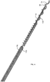
Figure 5 is an enlarged perspective view ofportion 5 of the cryoneedle shown inFigure 1A with the outer tube removed from the view to illustrate internal components housed therein; -
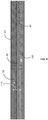
Figure 6 is an enlarged perspective view ofportion 6 of the cryoneedle shown inFigure 2 ; -
Figure 7A is a front view of a cryoneedle according to certain embodiments illustrated with an ellipsoidal iceball formed at its distal tip; and -
Figure 7B is a front view of a cryoneedle according to certain embodiments illustrated with a spherical iceball formed at its distal tip. - The following detailed description is exemplary in nature and is not intended to limit the scope, applicability, or configuration of the invention in any way. Rather, the following description provides some practical illustrations for implementing exemplary embodiments of the present invention. Examples of constructions, materials, dimensions, and manufacturing processes are provided for selected elements, and all other elements employ that which is known to those of ordinary skill in the field of the invention. Those skilled in the art will recognize that many of the noted examples have a variety of suitable alternatives.
- Cryosurgical systems can be used for cryoablating target tissues (e.g., a tumor). Typically, such systems include one or more cryoneedles, one or more cryogas sources and a controller. The cryogas sources can supply gases such as argon, nitrogen, air, krypton, C02, CF4, xenon, and various other gases. The cryosurgical system can also include a controller having one or more sensors, flow meters, timers, analog/digital converters, wired or wireless communication modules, etc. Additionally, the controller can also regulate the flow rate, temperature and pressure of cryogas supplied to the cryoneedle.
- During cryosurgery, for instance, a surgeon may deploy one or more cryoneedles such as those illustrated in
Fig. 1 to cryoablate a target area of a patient anatomy by placing thecryoneedle 10 at or near the target area of the patient anatomy. In one example,cryoneedle 10 utilizes the Joule-Thomson effect to produce cooling or heating. In such cases, a cryogas expands in the cryoneedle 10 from a higher pressure to a lower pressure. Expansion of the cryogas results in temperatures at or below those necessary for cryoablating a tissue in the vicinity of the tip of thecryoneedle 10. Heat transfer between the expanded cryogas and the outer walls of the cryoneedle 10 can be used to form an iceball, and consequently cryoablate the tissue. - As shown in
Figs. 1A-1B and2 , components of thecryoneedle 10 are located within an outer tube 12 (e.g., a trocar). Theouter tube 12 can have adistal operating head 16 disposed at adistal section 20 of the cryoneedle 10 for penetrating through tissues of a patient during deployment. Theouter tube 12 can be of substantially thin cross section for allowing deployment in tissues of a patient. In one example, theouter tube 12 has an outer diameter of about 2.1 millimeters. Other dimensions of theouter tube 12 are also contemplated. For example, theouter tube 12 can have an outer diameter of between about 1.5 millimeters and about 2.4 millimeters. As mentioned above, theouter tube 12 can have adistal section 20 placed at or near a target area of a patient's anatomy. Theouter tube 12 can also have amiddle section 24 positioned between thedistal section 20, and aproximal section 30 of the cryoneedle 10. Additionally, theouter tube 12 has a longitudinal axis 34. - As seen in
Fig. 2 , thecryoneedle 10 includes agas supply line 38 extending substantially along its length for providing a high-pressure gas to thedistal operating head 16. Thegas supply line 38 can be positioned coaxially/concentrically within theouter tube 12. Thegas supply line 38 can be configured to supply a cryogas for forming iceballs on anouter surface 40 of theouter tube 12 over thedistal section 20. In some cases, thegas supply line 38 can be a capillary tube. Referring to Fig. IB, thegas supply line 38 comprises aproximal heat exchanger 50 positioned in theproximal section 30 of thecryoneedle 10 and operably connected to a cryogas source (not shown) at afirst end 52 and the capillary tube at asecond end 54. Theproximal heat exchanger 50 can precool the cryogas from the cryogas source prior to being delivered to the middle and/or distal sections. - With continued reference to Fig. IB, the
proximal heat exchanger 50 can be a hollowhelical tube 56 wound around acentral core 58. Thehelical tube 56 of theproximal heat exchanger 50 provides increased heat exchange surface area per unit length of thehelical tube 56 in comparison to heat exchangers that are not coiled. Thehelical tube 56 can be made of brass. Other metals such as stainless steel are also contemplated. In the illustrated embodiment shown inFig. 1A , theproximal heat exchanger 50 is positioned far from thedistal operating head 16. For instance, theproximal heat exchanger 50 can be positioned at a handle (not shown). In such cases, an insulating outer cover (not shown) can be positioned over theproximal heat exchanger 50 so as to facilitate manual deployment (e.g., by grasping the handle) by an operator (e.g., a surgeon). The insulating outer cover can be made of heat shrink plastic film. In some cases, thecentral core 58 can be substantially rigid in comparison to thedistal operating head 16. Such embodiments can be beneficial in providing a cryoneedle 10 with a substantially flexibledistal operating head 16 for penetrating soft tissue and a substantially rigid handle having aproximal heat exchanger 50 to precool the cryogas. - Referring to
Fig. 2 , thedistal section 20 can have afirst portion 60 and asecond portion 70. Thecryoneedle 10 includes anexpansion chamber 72 within thefirst portion 60 of thedistal section 20 such that thegas supply line 38 terminates in theexpansion chamber 72. In some cases, the gas supply line 38 (e.g., capillary tube) can terminate in a Joule-Thomson orifice 74. The Joule-Thomson orifice 74 can be positioned near theexpansion chamber 72. A high-pressure cryogas supplied via thegas supply line 38 exitsgas supply line 38 via the Joule-Thomson orifice 74 and expands in theexpansion chamber 72. As the cryogas expands in theexpansion chamber 72, it cools rapidly and forms iceballs of different shapes and/or sizes over theouter surface 40 of theouter tube 12. The expansion of the cryogas can be such that when expanded, the cryogas is colder than the incoming cryogas. - With continued reference to
Fig. 2 , thecryoneedle 10 comprises a returngas flow lumen 78 defined annularly between theheat exchange helix 100 and the centralgas supply line 38. The returngas flow lumen 78 can carry cryogas from theexpansion chamber 72 toward theproximal section 30 of thecryoneedle 10 along areturn flow path 79 shown inFig. 2 . The returngas flow lumen 78 is defined along a return path of the cryogas between thegas supply line 38 and theinner wall 102 of theouter tube 12 of thecryoneedle 10. As will be described below, the returngas flow lumen 78 is helical in shape. Referring now toFigs. 4 and5 , and in operation, the cryogas expands in theexpansion chamber 72, and the expanded cryogas flows in the return flow lumen, thereby cooling incoming cryogas flowing through thegas supply line 38. The expanded gas can subsequently be exhausted to the atmosphere near an end of theouter tube 12. - Referring back to
Fig. 2 , aheater 80 cis provided within theouter tube 12 near thedistal section 20 to facilitate disengagement ofcryoneedle 10 after cryoablating a tissue, for thawing a tissue at or near thedistal section 20 of thecryoneedle 10, for cauterizing tissues, or for other purposes. As illustrated in this exemplary embodiment, anelectrical heater 80 is provided coaxially with thegas supply line 38 and theouter tube 12 to facilitate heating thedistal section 20 of thecryoneedle 10. Theelectrical heater 80 is a resistive heater, wherein theelectrical heater 80 generates heat proportional to the current flow therethrough and the electrical resistance ofelectrical heater 80. In such cases, as alluded to previously, the controller (not shown) can supply and/or regulate (e.g., with a Wheatstone bridge, ampere meter or voltmeter) electrical current flow to theelectrical heater 80 within thecryoneedle 10. In the embodiment illustrated inFig. 2 , theelectrical heater 80 comprises metal wires (e.g., copper) wound in helical coils (e.g., between about 50 coils and about 200 coils) around the gas supply tube. For instance, the wires are wound with a negligible pitch between adj acent coils of the wire. Additionally, the wires contact anouter surface 40 of the gas supply tube. - As mentioned previously, the temperature of the cryogas can be colder in the
first portion 60 of the distal section 20 (due to Joule-Thomson effect), than in thesecond portion 70, and heat transfer between the cryogas and theouter tube 12 can be higher over thefirst portion 60 than in thesecond portion 70. This can result in an iceball having an asymmetric shape (e.g., pear-shaped with the iceball generally tapering toward the second portion 70). To prevent asymmetric iceball formation, as seen inFigs. 2 and 3 , in one example, thecryoneedle 10 includes aheat exchange helix 100, comprising coils configured for enhancing heat exchange between the cryogas and theouter tube 12. Theheat exchange helix 100 contacts theinner wall 102 of theouter tube 12 and is positioned coaxially with theouter tube 12. As perhaps best seen inFig. 2 , the coils of theheat exchange helix 100 are in contact with theinner wall 102 of theouter tube 12 and do not contact theheater 80 or the gas supply line 38 (e.g., capillary tube). These coils effectively act as fins on theinner wall 102 of theouter tube 12 and improve heat transfer to theouter tube 12 to form iceballs having symmetric shapes wherein the symmetry is about the longitudinal axis 34 of theouter tube 12. - With continued reference to
Figs. 2 and 3 , the presence ofheat exchange helix 100 on theinner wall 102 of theouter tube 12 increases the surface area over which return gas flows over from theexpansion chamber 72 and toward theproximal section 30 of thecryoneedle 10. Moreover, the cryogas flows along a helical path from theexpansion chamber 72 toward theproximal section 30 of the cryoneedle 10 resulting in enhanced heat exchange. Such embodiments result in higher heat transfer between the expanded cryogas and theouter tube 12, consequently providing a desired iceball shape and size (e.g., a symmetric shape such as sphere or ellipsoid) as will be described below. Theheat exchange helix 100 enhances heat transfer over thedistal section 20 by increasing surface area over which heat transfer occurs from the cryogas to theouter tube 12 of thecryoneedle 10. For example, theheat exchange helix 100 provides a heat exchange surface area at thedistal section 20 and permits heat transfer between the cryogas and theouter tube 12 such that theouter tube 12 is evenly cooled to a temperature of about -150 degree Celsius when the cryogas temperature is about -155 degree Celsius. Other temperatures are also contemplated. For instance, theouter tube 12 can be cooled to any temperature in the range of between about -145 degree Celsius and about -150 degree Celsius, when the cryogas temperature is between about -155 degree Celsius and about - 150 degree Celsius. - The
heat exchange helix 100 can provide generally uniform cooling over the entire length 104 of thedistal section 20 such that the iceball (best illustrated inFigs. 7A and 7B ) is generally symmetric in shape. For instance, theheat exchange helix 100 can facilitate cooling theouter tube 12 evenly over the entire length 104 of thedistal section 20 such that the heat transfer rate between the cryogas and theouter tube 12 is approximately constant over the entire length 104 of thedistal section 20. As mentioned previously, the cryogas flowing in the return flow lumen over thefirst portion 60 can be at a lower temperature than the cryogas flowing in the return flow lumen over thesecond portion 70 because of rapid expansion of the cryogas near the Joule Thomson orifice and associate rapid cooling that occurs at thefirst portion 60. In such cases, theheat exchange helix 100 can increase heat transfer between cryogas and theouter tube 12 over thesecond portion 70 such that the heat transfer rate between the cryogas and theouter tube 12 over thefirst portion 60 roughly equals the heat transfer rate between the cryogas and theouter tube 12 over thesecond portion 70. Such embodiments can facilitate in generating iceballs having symmetric shape, and prevent formation of iceballs having asymmetric shapes (e.g., pear-shaped). - As seen in
Fig. 3 , theheat exchange helix 100 has a helix pitch. The helix pitch can be configured to generate aniceball 150 having a symmetrical shape (e.g., ellipsoidal or spherical). For example, as illustrated, the coils can have variable helix pitch. InFig. 3 , two helix pitches are shown: afirst pitch 108 over thefirst portion 60 of thedistal section 20 and asecond pitch 110 over thesecond portion 70 of thedistal section 20. Thefirst pitch 108 can be greater than thesecond pitch 110 such that adjacent coils of theheat exchange helix 100 are spaced further apart in thefirst portion 60 than in thesecond portion 70. For instance, theheat exchange helix 100 can have fewer coils per unit length in thefirst portion 60 than in thesecond portion 70. In the illustrated embodiment, theheat exchange helix 100 has a higher surface area per unit length in thesecond portion 70 of thedistal section 20 in comparison to the surface area per unit length in thefirst portion 60 of thedistal section 20. As the cryogas has a higher temperature in thesecond portion 70 than in thefirst portion 60, the increased surface area in thesecond portion 70 facilitates heat transfer rates between the cryogas and theouter tube 12 that is roughly equal so that the iceball 150 (best illustrated inFigs. 7A and 7B ) has a generally symmetric shape. Alternatively, the helix pitch can be constant over the entire length 104 of thedistal section 20. - In the embodiments illustrated herein, the
heat exchange helix 100 is a coiled spring. Theheat exchange helix 100 can be made of tin coated copper. Other metals and alloys (e.g., stainless steel) having sufficient resiliency and/or malleability so as to be formed into a helical shape of desired helix pitch are also contemplated. - Referring back to
Fig. 2 and referring now toFig. 4 , thecryoneedle 10 comprises an insulatingsheath 120 positionable at locations other than thedistal section 20. The insulatingsheath 120 abuts against theouter tube 12 to prevent the expanded cryogas returning from theexpansion chamber 72 from coming into contact with theouter tube 12. For example, the cold return gas avoids contact with areas of the patient's body other than intended the target area such that aniceball 150 is therefore formed in the exposed region of the outer tube 12 (e.g., regions of theouter tube 12 not having the insulatingsheath 120 positioned between theouter tube 12 and the return gas flow lumen 78). In the illustrated embodiment shown inFig. 2 , the entire length 104 of thedistal section 20 is exposed. Over this exposed region length 140, the expanded cryogas contacts theouter tube 12 of thecryoneedle 10 and forms aniceball 150. The insulated sheath is positioned over the entire length of themiddle section 24 of the cryoneedle 10 in this embodiment. Over the entire length of themiddle section 24, the cryogas is prevented from contacting theouter tube 12, thereby preventing cooling of tissue surrounding themiddle section 24 and/or iceball formation thereon. - In some cases, the exposed region length 140 (best seen in
Fig. 2 ) of theouter tube 12 can determine the shape of the iceball.Figs. 7A and 7B for instance illustrate an ellipsoidal and aspherical iceball 150 formed over thedistal section 20 of thecryoneedle 10, respectively. In one example, when the exposed region length 140 of theouter tube 12 is about 34 millimeters, theiceball 150 can have a substantially ellipsoidal shape such as that illustrated inFig. 7A . In another example, when the exposed region length 140 of theouter tube 12 is about 18 millimeters, theiceball 150 can have a substantially spherical shape such as that illustrated inFig. 7B . While in bothFigs. 7A and 7B , theiceball 150 formed is of a symmetric shape, the exposed region length 140 of the outer tube 12 (e.g., not covered by the insulating sheath 120) influences theaspect ratio 160 of theiceball 150 shape. For example, a shorter exposed region length produces aspherical iceball 150 and a longer exposed region length produces an ellipsoidal iceball. By shortening or extending the length of the insulatingsheath 120, various symmetric shapes can be obtained. The exposed region length 140 can thus be varied to change anaspect ratio 160 of theiceball 150. As illustrated inFigs. 7A and 7B ,aspect ratio 160 of theiceball 150 can be defined as the ratio oflength 162 of theiceball 150 measured along the lengthwise direction of thecryoneedle 10 and thewidth 164 of theiceball 150 measured in a direction perpendicular to the lengthwise direction of thecryoneedle 10. As illustrated, anaspect ratio 160 of about one implies aspherical iceball 150. - In some exemplary cases, the
heat exchange helix 100 disclosed herein can create additional resistance to flow of expanded cryogas in the returngas flow lumen 78. In such cases, the dimensions of the cryoneedle 10 can be configured to prevent excessive flow resistance and/or back pressure being generated in thecryoneedle 10. Referring now toFigs. 5 and6 , the insulatingsheath 120 can have dimensions suitable to permit the return flow of expanded cryogas from thedistal section 20 toward theproximal section 30. For instance, the insulatingsheath 120 can have aninner diameter 170 sufficient to create an annular gap between thegas supply line 38 and an outer wall of the insulatingsheath 120 as best seen inFigs 5 and6 . The annular gap being in fluid communication with the returngas flow lumen 78 to receive cryogas flowing therethrough. In one example, theinner diameter 170 of the insulatingsheath 120 is about 1.32 mm. In other examples, the insulatingsheath 120 can have aninner diameter 170 between about 0.5 millimeters and about 2 millimeters. In one example, when the outer diameter of theouter tube 12 is about 2.1 millimeters, the insulatingsheath 120 can have aninner diameter 170 of between about 1.0 millimeter and about 1.4 millimeters. In another example, when the outer diameter of theouter tube 12 is about 1.5 millimeters, the insulatingsheath 120 can have aninner diameter 170 of about 0.72 millimeters. In another example, when the outer diameter of theouter tube 12 is about 2.4 millimeters, the insulatingsheath 120 can have aninner diameter 170 of between about 1.25 millimeters and about 1.7 millimeters. Theinner diameter 170 of the insulatingsheath 120 can therefore be sufficiently large to minimize back pressure acting on the expanded cryogas flowing through the annular gap from the returngas flow lumen 78. In such cases, backpressure is minimized to allow the pressure of the expanding cryogas to fall as low as possible (e.g., zero gauge), which results in a lower gas temperature and bigger iceball. Maximizing theinner diameter 170 of the insulatingsheath 120 helps to minimize the overall backpressure of thecryoneedle 10. - A method of forming ice balls having a symmetric shape during cryosurgery can comprise the step of providing a cryosurgery system such as those disclosed herein, supplying a cryogas through the
gas supply line 38, expanding the cryogas in theexpansion chamber 72, providing a helical return path for cryogas in thedistal section 20, the cryogas flowing in the returngas flow lumen 78 in a direction from theexpansion chamber 72 toward aproximal section 30, and forming aniceball 150 on anouter surface 40 of theouter tube 12 over thedistal section 20 such that theiceball 150 has a generally symmetric shape. - Embodiments of the cryoneedle 10 disclosed herein can provide several advantages. The cryoneedle 10 can be configured such that substantially symmetric iceballs having desirable shapes. The cryoneedle 10 can enhance heat transfer over portions of its
distal section 20 such that desirable iceball characteristics (e.g., symmetry, size and shape) can be obtained with a smaller needleouter tube 12 diameter. Moreover, because of the smaller needleouter tube 12 diameter, the weight and torque on the needle handle are also minimized making the cryoneedle 10 easily deployable during cryosurgery. - Thus, embodiments of
cryoneedle 10 with evenly distributed cooling are disclosed. Although the present embodiments have been described in considerable detail with reference to certain disclosed embodiments, the disclosed embodiments are presented for purposes of illustration and not limitation. One skilled in the art will appreciate that various changes, adaptations, and modifications may be made.
Claims (17)
- A cryoneedle comprising:an outer tube (12) having a distal section (20) placed at or near a target area of a patient's anatomy and a longitudinal axis;a gas supply line (38) positioned within the outer tube, the gas supply line configured to supply a cryogas for forming an ice ball on an outer surface (40) of the outer tube over the distal section;an expansion chamber (72) located within the distal section such that the gas supply line terminates in the expansion chamber; a heat exchange helix in the outer tube;a return gas flow lumen (78) defined annularly between the heat exchange helix (100) and the gas supply line (38) adapted to carry cryogas from the expansion chamber (72) along a return flow path (79);an electrical resistance heater (80) positioned coaxially with the gas supply line (38) and the outer tube to facilitate heating of the distal section (20) of the cryoneedle;characterised in that:the heat exchange helix (100) contacts the innersurface of the outer tube; but is not in contact with the electrical resistance heater (80) or the gas supply line (38);the electrical resistance heater (80) comprises metal wires wound in helical coils around and in contact with an outer surface (40) of the gas supply line (38); andwherein the heat exchange helix (100) adapted to provide generally uniform rate of heat transfer in the distal section (20) such that the iceball formed on the outer surface (40) of the outer tube (12) is generally symmetric in shape along the longitudinal axis of the outer tube.
- The cryoneedle of claim 1, wherein the heat exchange helix (100) is positioned coaxially with an axis of the outer tube (12).
- The cryoneedle of claim 1, wherein the outer tube (21) has an outer diameter of about 2.1 millimeters.
- The cryoneedle of claim 1, wherein the expansion chamber (72) is adapted to expand the cryogas, and the expanded cryogas flowing in the return flow lumen (78) is adapted to cool incoming cryogas flowing through the gas supply line (38).
- The cryoneedle of claim 1, wherein the heat exchange helix (100) has a helix pitch defined axially between adjacent turns of the heat exchange helix, the helix pitch being configurable along the heat exchange helix to generate an iceball having ellipsoidal or spherical shape.
- The cryoneedle of claim 5, wherein the helix pitch along the heat exchange helix (100) is constant substantially over the distal section (20).
- The cryoneedle of claim 5, wherein the heat exchange helix along the heat exchange helix (100) has a first pitch (108) over a first portion of the distal section and a second pitch (110) over a second portion of the distal section.
- The cryoneedle of claim 7, wherein the first pitch (108) is greater than the second pitch (110), such that the cryogas enhances heat transfer over the second portion of the distal section such that the iceball has a symmetric shape.
- The cryoneedle of claim 1, wherein the heat exchange helix (100) is a helical spring.
- The cryoneedle of claim 9, wherein the heat exchange helix (100) is made of a metal alloy comprising copper with a coating of tin.
- The cryoneedle of claim 1, wherein the heat exchange helix (100) has a heat exchange surface area at the distal section, the heat exchange surface area providing sufficient heat transfer between the cryogas and the outer tube such that the outer tube is cooled to a temperature of between about -150 degree Celsius and about -145 degree Celsius when the cryogas temperature is about -155 degree Celsius and about -150 degree Celsius respectively.
- The cryoneedle of claim 1, further comprising an insulating sheath (120) substantially surrounding the gas supply line (38) and thereby forming a barrier between the return gas flow lumen (78) and the outer tube (12) over a portion of a length of the outer tube, the insulating sheath (120) having an inner diameter sufficient to create an annular gap between the gas supply line (38) and an inner wall (102) of the insulating sheath, the annular gap being in fluid communication with the return gas flow lumen (78) to receive cryogas flowing therethrough.
- The cryoneedle of claim 12, wherein the inner diameter of the insulating sheath (120) is about 1.32 mm.
- The cryoneedle of claim 12, wherein the insulating sheath (120) surrounds the gas supply line (38) over a portion of the length of the outer tube (12) such that expanded cryogas directly contacts the outer tube over an exposed region, the exposed region having an exposed region length, the exposed region length (140) adapted to generate an iceball having a predetermined aspect ratio.
- The cryoneedle of claim 12, wherein the annular gap defined between the outer wall (12) of the insulating sheath (120) and the gas supply line (38) has a diameter sufficient to minimize back pressure acting on the expanded cryogas flowing through the annular gap from the return gas flow lumen (78).
- The cryoneedle of claim 1, wherein the gas supply line (38) is coaxial with the longitudinal axis of the outer tube (12).
- The cryoneedle of claim 1, wherein the heat exchange helix (100) contacts the inner surface of the outer tube (12) at the distal section.
Priority Applications (1)
| Application Number | Priority Date | Filing Date | Title |
|---|---|---|---|
| EP20165024.9A EP3741319B1 (en) | 2015-02-20 | 2016-02-12 | Cryoneedle |
Applications Claiming Priority (2)
| Application Number | Priority Date | Filing Date | Title |
|---|---|---|---|
| US14/627,568 US10390871B2 (en) | 2015-02-20 | 2015-02-20 | Cryoneedle |
| PCT/US2016/017828 WO2016133826A1 (en) | 2015-02-20 | 2016-02-12 | Cryoneedle |
Related Child Applications (2)
| Application Number | Title | Priority Date | Filing Date |
|---|---|---|---|
| EP20165024.9A Division EP3741319B1 (en) | 2015-02-20 | 2016-02-12 | Cryoneedle |
| EP20165024.9A Division-Into EP3741319B1 (en) | 2015-02-20 | 2016-02-12 | Cryoneedle |
Publications (3)
| Publication Number | Publication Date |
|---|---|
| EP3258869A1 EP3258869A1 (en) | 2017-12-27 |
| EP3258869B1 true EP3258869B1 (en) | 2020-03-25 |
| EP3258869B8 EP3258869B8 (en) | 2020-04-29 |
Family
ID=55456922
Family Applications (2)
| Application Number | Title | Priority Date | Filing Date |
|---|---|---|---|
| EP20165024.9A Active EP3741319B1 (en) | 2015-02-20 | 2016-02-12 | Cryoneedle |
| EP16708281.7A Active EP3258869B8 (en) | 2015-02-20 | 2016-02-12 | Cryoneedle |
Family Applications Before (1)
| Application Number | Title | Priority Date | Filing Date |
|---|---|---|---|
| EP20165024.9A Active EP3741319B1 (en) | 2015-02-20 | 2016-02-12 | Cryoneedle |
Country Status (10)
| Country | Link |
|---|---|
| US (2) | US10390871B2 (en) |
| EP (2) | EP3741319B1 (en) |
| JP (2) | JP6871166B2 (en) |
| KR (1) | KR102612115B1 (en) |
| CN (2) | CN107205767B (en) |
| AU (3) | AU2016220282B2 (en) |
| CA (1) | CA2976224A1 (en) |
| IL (2) | IL281288B (en) |
| SG (1) | SG11201705976UA (en) |
| WO (1) | WO2016133826A1 (en) |
Families Citing this family (26)
| Publication number | Priority date | Publication date | Assignee | Title |
|---|---|---|---|---|
| KR102480368B1 (en) | 2012-08-16 | 2022-12-23 | 에노빅스 코오퍼레이션 | Electrode structures for three-dimensional batteries |
| EP4358271A3 (en) | 2013-03-15 | 2024-07-24 | Enovix Corporation | Three-dimensional batteries |
| US10390871B2 (en) * | 2015-02-20 | 2019-08-27 | Galil Medical Inc. | Cryoneedle |
| TWI896945B (en) | 2015-05-14 | 2025-09-11 | 美商易諾維公司 | Longitudinal constraints for energy storage devices |
| EP3455898B1 (en) | 2016-05-13 | 2024-06-26 | Enovix Corporation | Dimensional constraints for three-dimensional batteries |
| WO2018093965A1 (en) | 2016-11-16 | 2018-05-24 | Enovix Corporation | Three-dimensional batteries with compressible cathodes |
| CN107997818A (en) * | 2017-11-10 | 2018-05-08 | 上海导向医疗系统有限公司 | The cryoablation pin of rewarming and thermotherapeutic function is realized by electric heating wire |
| EP3709914A1 (en) | 2017-11-13 | 2020-09-23 | Biocompatibles UK Limited | Cryoprobe for magnetic resonance imaging |
| WO2019092627A1 (en) | 2017-11-13 | 2019-05-16 | Biocompatibles Uk Limited | Cryoablation system with magnetic resonance imaging detection |
| TWI896933B (en) | 2017-11-15 | 2025-09-11 | 美商易諾維公司 | Electrode assembly, secondary battery, and method of manufacture |
| US10256507B1 (en) | 2017-11-15 | 2019-04-09 | Enovix Corporation | Constrained electrode assembly |
| WO2019142278A1 (en) * | 2018-01-17 | 2019-07-25 | オリンパス株式会社 | Heating device, treatment system, and heating control method |
| US11211639B2 (en) | 2018-08-06 | 2021-12-28 | Enovix Corporation | Electrode assembly manufacture and device |
| CN111374751B (en) | 2018-12-28 | 2021-05-28 | 上海微创电生理医疗科技股份有限公司 | Electrophysiology catheter and ablation system |
| CN110251224B (en) * | 2019-08-13 | 2020-02-07 | 上海导向医疗系统有限公司 | Adjustable cryoablation needle |
| US11633224B2 (en) | 2020-02-10 | 2023-04-25 | Icecure Medical Ltd. | Cryogen pump |
| EP4200921B1 (en) | 2020-09-18 | 2024-08-14 | Enovix Corporation | Process for delineating a population of electrode structures in a web using a laser beam |
| CN112294422B (en) * | 2020-10-08 | 2022-01-28 | 苏州优脉瑞医疗科技有限公司 | Endoscope refrigerating machine with auxiliary monitoring probe |
| EP4002537A1 (en) * | 2020-11-18 | 2022-05-25 | Enovix Operations Inc. | Spacers for electrodes, electrode stacks and batteries and systems and methods therefor |
| CN116783744A (en) | 2020-12-09 | 2023-09-19 | 艾诺维克斯公司 | Method and device for manufacturing electrode assembly of secondary battery |
| US12426934B2 (en) | 2022-02-28 | 2025-09-30 | Icecure Medical Ltd. | Cryogen flow control |
| US12215811B2 (en) | 2022-07-18 | 2025-02-04 | Icecure Medical Ltd. | Cryogenic system connector |
| US12527613B2 (en) | 2023-09-11 | 2026-01-20 | Icecure Medical Ltd. | Cryoprobe |
| US20260041476A1 (en) * | 2024-08-12 | 2026-02-12 | Varian Medical Systems, Inc. | Cryoablation probes with heat exchanger in return cryogen line |
| US20260060737A1 (en) * | 2024-08-30 | 2026-03-05 | Varian Medical Systems, Inc. | Heaters for cryoablation probes with movable insulating sleeves |
| US20260060738A1 (en) | 2024-09-03 | 2026-03-05 | Boston Scientific Scimed, Inc. | Closed-loop cryoablation system and method |
Citations (3)
| Publication number | Priority date | Publication date | Assignee | Title |
|---|---|---|---|---|
| US20060122590A1 (en) * | 2004-12-06 | 2006-06-08 | Galil Medical Ltd. | Gas-heated gas-cooled cryoprobe utilizing electrical heating and a single gas source |
| US20100256620A1 (en) * | 2006-01-12 | 2010-10-07 | Galil Medical Ltd. | Thin flexible cryoprobe operated by krypton |
| WO2014144626A2 (en) * | 2013-03-15 | 2014-09-18 | Endocare, Inc. | Cryogenic system and methods |
Family Cites Families (43)
| Publication number | Priority date | Publication date | Assignee | Title |
|---|---|---|---|---|
| US3477434A (en) * | 1965-06-02 | 1969-11-11 | Cvi Corp | Cryosurgical apparatus |
| FR1591369A (en) * | 1967-11-10 | 1970-04-27 | ||
| DE1953835B2 (en) * | 1969-10-25 | 1972-02-24 | Linde Ag, 6200 Wiesbaden | CRYOSURGICAL DEVICE |
| NL176833C (en) | 1973-04-26 | 1985-06-17 | Draegerwerk Ag | HEAT-INSULATING FLEXIBLE PIPE. |
| DE2736113C2 (en) * | 1977-08-10 | 1987-02-12 | Erbe Elektromedizin GmbH, 7400 Tübingen | Probe for performing prostate treatments |
| US4444156A (en) * | 1980-05-28 | 1984-04-24 | Kabushiki Kaisha Youei Seisakusho | Water heater |
| IL104506A (en) * | 1993-01-25 | 1997-11-20 | Israel State | Fast changing heating- cooling device and method, particularly for cryogenic and/or surgical use |
| US6530922B2 (en) * | 1993-12-15 | 2003-03-11 | Sherwood Services Ag | Cluster ablation electrode system |
| US6505629B1 (en) | 1996-07-23 | 2003-01-14 | Endocare, Inc. | Cryosurgical system with protective warming feature |
| US5800488A (en) | 1996-07-23 | 1998-09-01 | Endocare, Inc. | Cryoprobe with warming feature |
| US5916212A (en) * | 1998-01-23 | 1999-06-29 | Cryomedical Sciences, Inc. | Hand held cyrosurgical probe system |
| GB2336781B (en) | 1998-04-30 | 2001-03-07 | Spembly Medical Ltd | Cryosurgical apparatus |
| US6270476B1 (en) | 1999-04-23 | 2001-08-07 | Cryocath Technologies, Inc. | Catheter |
| US6706037B2 (en) | 2000-10-24 | 2004-03-16 | Galil Medical Ltd. | Multiple cryoprobe apparatus and method |
| ATE313493T1 (en) * | 2001-09-19 | 2006-01-15 | Meadwestvaco Packaging Systems | ARTICLE CARRIER WITH AUTOMATIC END STOCKING MEANS |
| US6767346B2 (en) * | 2001-09-20 | 2004-07-27 | Endocare, Inc. | Cryosurgical probe with bellows shaft |
| US7147656B2 (en) | 2001-12-03 | 2006-12-12 | Xtent, Inc. | Apparatus and methods for delivery of braided prostheses |
| US7479139B2 (en) | 2002-01-04 | 2009-01-20 | Galil Medical Ltd. | Apparatus and method for protecting tissues during cryoablation |
| CN1212103C (en) * | 2002-09-03 | 2005-07-27 | 柯钢 | Circumferentia weld throttling type cryoprobe |
| US6936048B2 (en) * | 2003-01-16 | 2005-08-30 | Charlotte-Mecklenburg Hospital Authority | Echogenic needle for transvaginal ultrasound directed reduction of uterine fibroids and an associated method |
| US7160291B2 (en) | 2003-06-25 | 2007-01-09 | Endocare, Inc. | Detachable cryosurgical probe |
| US6857187B2 (en) | 2003-07-03 | 2005-02-22 | Jeffrey S Epstein | Method of manufacturing a measuring wheel for wireline operations |
| JP4494255B2 (en) * | 2005-03-07 | 2010-06-30 | 大王製紙株式会社 | Absorbent articles |
| US20070014995A1 (en) * | 2005-07-12 | 2007-01-18 | Jacob Chacko | Thin rotary-fiberized glass insulation and process for producing same |
| US20070149959A1 (en) * | 2005-12-23 | 2007-06-28 | Sanarus Medical, Inc. | Cryoprobe for low pressure systems |
| US7785289B2 (en) * | 2006-10-17 | 2010-08-31 | Boston Scientific Scimed, Inc. | Catheter with flexible, non-kinking elongate member |
| US7909227B2 (en) * | 2006-12-19 | 2011-03-22 | Endocare, Inc. | Cryosurgical probe with vacuum insulation tube assembly |
| DE102008010477A1 (en) * | 2008-02-21 | 2009-09-03 | Erbe Elektromedizin Gmbh | Cryosurgical instrument |
| JP5476375B2 (en) * | 2008-07-10 | 2014-04-23 | エルベ エレクトロメディツィン ゲーエムベーハー | Electrosurgical equipment |
| US20100114275A1 (en) * | 2008-10-30 | 2010-05-06 | Pacesetter, Inc. | Implantable medical lead including winding for improved mri safety |
| US8915908B2 (en) * | 2009-03-20 | 2014-12-23 | Atricure, Inc. | Cryogenic probe |
| WO2012116265A2 (en) * | 2011-02-24 | 2012-08-30 | MRI Interventions, Inc. | Mri-guided catheters |
| JP4580450B1 (en) * | 2009-07-03 | 2010-11-10 | 株式会社日立製作所 | Recording power adjustment method, information recording method and evaluation method |
| US7967815B1 (en) * | 2010-03-25 | 2011-06-28 | Icecure Medical Ltd. | Cryosurgical instrument with enhanced heat transfer |
| US9936996B2 (en) * | 2010-03-30 | 2018-04-10 | Medtronic ATS Medical, Inc. | Cryoprobe having internal warming fluid capabilities |
| US20110264084A1 (en) * | 2010-04-23 | 2011-10-27 | Concept Group, Inc. | Vacuum insulated cooling probe with heat exchanger |
| WO2012036914A1 (en) * | 2010-09-15 | 2012-03-22 | Icecure Medical Ltd. | Cryosurgical instrument for treating large volume of tissue |
| US9084610B2 (en) * | 2010-10-21 | 2015-07-21 | Medtronic Ardian Luxembourg S.A.R.L. | Catheter apparatuses, systems, and methods for renal neuromodulation |
| CN103442657B (en) | 2011-05-11 | 2016-05-25 | 艾斯酷瑞医药有限公司 | For the coil exchanger of Cryobiopsy probe |
| US20130090638A1 (en) * | 2011-10-07 | 2013-04-11 | Galil Medical Inc. | Flexible Cryoneedle Apparatus and Method |
| US9566105B2 (en) * | 2012-02-07 | 2017-02-14 | Cpsi Holdings Llc | Dual thermal ablation device and method of use |
| CN203122580U (en) * | 2013-03-29 | 2013-08-14 | 北京阳光易帮医疗科技有限公司 | Ultra-low temperature freezing probe head |
| US10390871B2 (en) | 2015-02-20 | 2019-08-27 | Galil Medical Inc. | Cryoneedle |
-
2015
- 2015-02-20 US US14/627,568 patent/US10390871B2/en active Active
-
2016
- 2016-02-12 EP EP20165024.9A patent/EP3741319B1/en active Active
- 2016-02-12 WO PCT/US2016/017828 patent/WO2016133826A1/en not_active Ceased
- 2016-02-12 EP EP16708281.7A patent/EP3258869B8/en active Active
- 2016-02-12 KR KR1020177022304A patent/KR102612115B1/en active Active
- 2016-02-12 CA CA2976224A patent/CA2976224A1/en active Pending
- 2016-02-12 CN CN201680008487.5A patent/CN107205767B/en active Active
- 2016-02-12 IL IL281288A patent/IL281288B/en unknown
- 2016-02-12 SG SG11201705976UA patent/SG11201705976UA/en unknown
- 2016-02-12 CN CN202011072540.2A patent/CN112220550B/en active Active
- 2016-02-12 AU AU2016220282A patent/AU2016220282B2/en active Active
- 2016-02-12 JP JP2017542894A patent/JP6871166B2/en active Active
-
2017
- 2017-07-31 IL IL253740A patent/IL253740B/en active IP Right Grant
-
2019
- 2019-06-07 US US16/434,942 patent/US11832867B2/en active Active
-
2020
- 2020-10-01 AU AU2020244547A patent/AU2020244547B2/en not_active Expired - Fee Related
- 2020-12-02 JP JP2020200286A patent/JP7308181B2/en active Active
-
2022
- 2022-02-25 AU AU2022201326A patent/AU2022201326B2/en active Active
Patent Citations (3)
| Publication number | Priority date | Publication date | Assignee | Title |
|---|---|---|---|---|
| US20060122590A1 (en) * | 2004-12-06 | 2006-06-08 | Galil Medical Ltd. | Gas-heated gas-cooled cryoprobe utilizing electrical heating and a single gas source |
| US20100256620A1 (en) * | 2006-01-12 | 2010-10-07 | Galil Medical Ltd. | Thin flexible cryoprobe operated by krypton |
| WO2014144626A2 (en) * | 2013-03-15 | 2014-09-18 | Endocare, Inc. | Cryogenic system and methods |
Also Published As
| Publication number | Publication date |
|---|---|
| EP3741319A1 (en) | 2020-11-25 |
| EP3258869B8 (en) | 2020-04-29 |
| AU2016220282A1 (en) | 2017-08-17 |
| KR102612115B1 (en) | 2023-12-08 |
| US20190350633A1 (en) | 2019-11-21 |
| AU2022201326A1 (en) | 2022-03-24 |
| AU2020244547A1 (en) | 2020-10-29 |
| IL253740B (en) | 2021-03-25 |
| CN112220550B (en) | 2024-05-28 |
| CA2976224A1 (en) | 2016-08-25 |
| KR20170118717A (en) | 2017-10-25 |
| CN107205767A (en) | 2017-09-26 |
| US10390871B2 (en) | 2019-08-27 |
| IL281288B (en) | 2022-07-01 |
| JP6871166B2 (en) | 2021-05-12 |
| WO2016133826A1 (en) | 2016-08-25 |
| AU2016220282B2 (en) | 2020-07-02 |
| IL281288A (en) | 2021-04-29 |
| IL253740A0 (en) | 2017-09-28 |
| US20160242835A1 (en) | 2016-08-25 |
| EP3741319B1 (en) | 2023-07-26 |
| SG11201705976UA (en) | 2017-09-28 |
| EP3258869A1 (en) | 2017-12-27 |
| US11832867B2 (en) | 2023-12-05 |
| AU2020244547B2 (en) | 2021-11-25 |
| JP2021072875A (en) | 2021-05-13 |
| CN112220550A (en) | 2021-01-15 |
| CN107205767B (en) | 2020-10-27 |
| JP7308181B2 (en) | 2023-07-13 |
| AU2022201326B2 (en) | 2024-02-15 |
| JP2018505741A (en) | 2018-03-01 |
Similar Documents
| Publication | Publication Date | Title |
|---|---|---|
| AU2020244547B2 (en) | Cryoneedle | |
| EP1435825B1 (en) | Malleable cryosurgical probe | |
| EP0925045B1 (en) | Cryoprobe | |
| US7361187B2 (en) | Threaded cryostat for cryosurgical probe system | |
| CN101969872A (en) | Cryosurgical instrument | |
| HK1242544A1 (en) | Cryoneedle | |
| AU754411B2 (en) | Cryoprobe | |
| WO2005104974A2 (en) | Threaded cryostat for cryosurgical probe system |
Legal Events
| Date | Code | Title | Description |
|---|---|---|---|
| STAA | Information on the status of an ep patent application or granted ep patent |
Free format text: STATUS: THE INTERNATIONAL PUBLICATION HAS BEEN MADE |
|
| PUAI | Public reference made under article 153(3) epc to a published international application that has entered the european phase |
Free format text: ORIGINAL CODE: 0009012 |
|
| STAA | Information on the status of an ep patent application or granted ep patent |
Free format text: STATUS: REQUEST FOR EXAMINATION WAS MADE |
|
| 17P | Request for examination filed |
Effective date: 20170811 |
|
| AK | Designated contracting states |
Kind code of ref document: A1 Designated state(s): AL AT BE BG CH CY CZ DE DK EE ES FI FR GB GR HR HU IE IS IT LI LT LU LV MC MK MT NL NO PL PT RO RS SE SI SK SM TR |
|
| AX | Request for extension of the european patent |
Extension state: BA ME |
|
| RIN1 | Information on inventor provided before grant (corrected) |
Inventor name: JOHNSON, MARK TIMOTHY Inventor name: BLEIWIES, MODECHAY Inventor name: ZACHMAN, ANDREW KEVIN Inventor name: RAMADHYANI, SATISH |
|
| DAV | Request for validation of the european patent (deleted) | ||
| DAX | Request for extension of the european patent (deleted) | ||
| STAA | Information on the status of an ep patent application or granted ep patent |
Free format text: STATUS: EXAMINATION IS IN PROGRESS |
|
| 17Q | First examination report despatched |
Effective date: 20180711 |
|
| GRAP | Despatch of communication of intention to grant a patent |
Free format text: ORIGINAL CODE: EPIDOSNIGR1 |
|
| STAA | Information on the status of an ep patent application or granted ep patent |
Free format text: STATUS: GRANT OF PATENT IS INTENDED |
|
| INTG | Intention to grant announced |
Effective date: 20190923 |
|
| GRAS | Grant fee paid |
Free format text: ORIGINAL CODE: EPIDOSNIGR3 |
|
| GRAA | (expected) grant |
Free format text: ORIGINAL CODE: 0009210 |
|
| STAA | Information on the status of an ep patent application or granted ep patent |
Free format text: STATUS: THE PATENT HAS BEEN GRANTED |
|
| AK | Designated contracting states |
Kind code of ref document: B1 Designated state(s): AL AT BE BG CH CY CZ DE DK EE ES FI FR GB GR HR HU IE IS IT LI LT LU LV MC MK MT NL NO PL PT RO RS SE SI SK SM TR |
|
| REG | Reference to a national code |
Ref country code: GB Ref legal event code: FG4D |
|
| REG | Reference to a national code |
Ref country code: DE Ref legal event code: R081 Ref document number: 602016032474 Country of ref document: DE Owner name: BOSTON SCIENTIFIC SCIMED, INC., MAPLE GROVE, US Free format text: FORMER OWNER: GALIL MEDICAL INC., ARDEN HILLS, MN, US |
|
| RAP2 | Party data changed (patent owner data changed or rights of a patent transferred) |
Owner name: BOSTON SCIENTIFIC SCIMED, INC. |
|
| REG | Reference to a national code |
Ref country code: AT Ref legal event code: REF Ref document number: 1247661 Country of ref document: AT Kind code of ref document: T Effective date: 20200415 Ref country code: CH Ref legal event code: PK Free format text: BERICHTIGUNG B8 Ref country code: IE Ref legal event code: FG4D |
|
| REG | Reference to a national code |
Ref country code: DE Ref legal event code: R096 Ref document number: 602016032474 Country of ref document: DE |
|
| PG25 | Lapsed in a contracting state [announced via postgrant information from national office to epo] |
Ref country code: NO Free format text: LAPSE BECAUSE OF FAILURE TO SUBMIT A TRANSLATION OF THE DESCRIPTION OR TO PAY THE FEE WITHIN THE PRESCRIBED TIME-LIMIT Effective date: 20200625 Ref country code: FI Free format text: LAPSE BECAUSE OF FAILURE TO SUBMIT A TRANSLATION OF THE DESCRIPTION OR TO PAY THE FEE WITHIN THE PRESCRIBED TIME-LIMIT Effective date: 20200325 Ref country code: RS Free format text: LAPSE BECAUSE OF FAILURE TO SUBMIT A TRANSLATION OF THE DESCRIPTION OR TO PAY THE FEE WITHIN THE PRESCRIBED TIME-LIMIT Effective date: 20200325 |
|
| REG | Reference to a national code |
Ref country code: NL Ref legal event code: FP |
|
| PG25 | Lapsed in a contracting state [announced via postgrant information from national office to epo] |
Ref country code: LV Free format text: LAPSE BECAUSE OF FAILURE TO SUBMIT A TRANSLATION OF THE DESCRIPTION OR TO PAY THE FEE WITHIN THE PRESCRIBED TIME-LIMIT Effective date: 20200325 Ref country code: SE Free format text: LAPSE BECAUSE OF FAILURE TO SUBMIT A TRANSLATION OF THE DESCRIPTION OR TO PAY THE FEE WITHIN THE PRESCRIBED TIME-LIMIT Effective date: 20200325 Ref country code: HR Free format text: LAPSE BECAUSE OF FAILURE TO SUBMIT A TRANSLATION OF THE DESCRIPTION OR TO PAY THE FEE WITHIN THE PRESCRIBED TIME-LIMIT Effective date: 20200325 Ref country code: GR Free format text: LAPSE BECAUSE OF FAILURE TO SUBMIT A TRANSLATION OF THE DESCRIPTION OR TO PAY THE FEE WITHIN THE PRESCRIBED TIME-LIMIT Effective date: 20200626 Ref country code: BG Free format text: LAPSE BECAUSE OF FAILURE TO SUBMIT A TRANSLATION OF THE DESCRIPTION OR TO PAY THE FEE WITHIN THE PRESCRIBED TIME-LIMIT Effective date: 20200625 |
|
| REG | Reference to a national code |
Ref country code: LT Ref legal event code: MG4D |
|
| PG25 | Lapsed in a contracting state [announced via postgrant information from national office to epo] |
Ref country code: PT Free format text: LAPSE BECAUSE OF FAILURE TO SUBMIT A TRANSLATION OF THE DESCRIPTION OR TO PAY THE FEE WITHIN THE PRESCRIBED TIME-LIMIT Effective date: 20200818 Ref country code: IS Free format text: LAPSE BECAUSE OF FAILURE TO SUBMIT A TRANSLATION OF THE DESCRIPTION OR TO PAY THE FEE WITHIN THE PRESCRIBED TIME-LIMIT Effective date: 20200725 Ref country code: CZ Free format text: LAPSE BECAUSE OF FAILURE TO SUBMIT A TRANSLATION OF THE DESCRIPTION OR TO PAY THE FEE WITHIN THE PRESCRIBED TIME-LIMIT Effective date: 20200325 Ref country code: SM Free format text: LAPSE BECAUSE OF FAILURE TO SUBMIT A TRANSLATION OF THE DESCRIPTION OR TO PAY THE FEE WITHIN THE PRESCRIBED TIME-LIMIT Effective date: 20200325 Ref country code: EE Free format text: LAPSE BECAUSE OF FAILURE TO SUBMIT A TRANSLATION OF THE DESCRIPTION OR TO PAY THE FEE WITHIN THE PRESCRIBED TIME-LIMIT Effective date: 20200325 Ref country code: RO Free format text: LAPSE BECAUSE OF FAILURE TO SUBMIT A TRANSLATION OF THE DESCRIPTION OR TO PAY THE FEE WITHIN THE PRESCRIBED TIME-LIMIT Effective date: 20200325 Ref country code: LT Free format text: LAPSE BECAUSE OF FAILURE TO SUBMIT A TRANSLATION OF THE DESCRIPTION OR TO PAY THE FEE WITHIN THE PRESCRIBED TIME-LIMIT Effective date: 20200325 Ref country code: SK Free format text: LAPSE BECAUSE OF FAILURE TO SUBMIT A TRANSLATION OF THE DESCRIPTION OR TO PAY THE FEE WITHIN THE PRESCRIBED TIME-LIMIT Effective date: 20200325 |
|
| REG | Reference to a national code |
Ref country code: AT Ref legal event code: MK05 Ref document number: 1247661 Country of ref document: AT Kind code of ref document: T Effective date: 20200325 |
|
| REG | Reference to a national code |
Ref country code: DE Ref legal event code: R097 Ref document number: 602016032474 Country of ref document: DE |
|
| PG25 | Lapsed in a contracting state [announced via postgrant information from national office to epo] |
Ref country code: IT Free format text: LAPSE BECAUSE OF FAILURE TO SUBMIT A TRANSLATION OF THE DESCRIPTION OR TO PAY THE FEE WITHIN THE PRESCRIBED TIME-LIMIT Effective date: 20200325 Ref country code: AT Free format text: LAPSE BECAUSE OF FAILURE TO SUBMIT A TRANSLATION OF THE DESCRIPTION OR TO PAY THE FEE WITHIN THE PRESCRIBED TIME-LIMIT Effective date: 20200325 Ref country code: DK Free format text: LAPSE BECAUSE OF FAILURE TO SUBMIT A TRANSLATION OF THE DESCRIPTION OR TO PAY THE FEE WITHIN THE PRESCRIBED TIME-LIMIT Effective date: 20200325 Ref country code: ES Free format text: LAPSE BECAUSE OF FAILURE TO SUBMIT A TRANSLATION OF THE DESCRIPTION OR TO PAY THE FEE WITHIN THE PRESCRIBED TIME-LIMIT Effective date: 20200325 |
|
| PLBE | No opposition filed within time limit |
Free format text: ORIGINAL CODE: 0009261 |
|
| STAA | Information on the status of an ep patent application or granted ep patent |
Free format text: STATUS: NO OPPOSITION FILED WITHIN TIME LIMIT |
|
| PG25 | Lapsed in a contracting state [announced via postgrant information from national office to epo] |
Ref country code: PL Free format text: LAPSE BECAUSE OF FAILURE TO SUBMIT A TRANSLATION OF THE DESCRIPTION OR TO PAY THE FEE WITHIN THE PRESCRIBED TIME-LIMIT Effective date: 20200325 |
|
| 26N | No opposition filed |
Effective date: 20210112 |
|
| PG25 | Lapsed in a contracting state [announced via postgrant information from national office to epo] |
Ref country code: SI Free format text: LAPSE BECAUSE OF FAILURE TO SUBMIT A TRANSLATION OF THE DESCRIPTION OR TO PAY THE FEE WITHIN THE PRESCRIBED TIME-LIMIT Effective date: 20200325 |
|
| PG25 | Lapsed in a contracting state [announced via postgrant information from national office to epo] |
Ref country code: MC Free format text: LAPSE BECAUSE OF FAILURE TO SUBMIT A TRANSLATION OF THE DESCRIPTION OR TO PAY THE FEE WITHIN THE PRESCRIBED TIME-LIMIT Effective date: 20200325 |
|
| REG | Reference to a national code |
Ref country code: BE Ref legal event code: MM Effective date: 20210228 |
|
| PG25 | Lapsed in a contracting state [announced via postgrant information from national office to epo] |
Ref country code: LU Free format text: LAPSE BECAUSE OF NON-PAYMENT OF DUE FEES Effective date: 20210212 Ref country code: LI Free format text: LAPSE BECAUSE OF NON-PAYMENT OF DUE FEES Effective date: 20210228 Ref country code: CH Free format text: LAPSE BECAUSE OF NON-PAYMENT OF DUE FEES Effective date: 20210228 |
|
| PG25 | Lapsed in a contracting state [announced via postgrant information from national office to epo] |
Ref country code: BE Free format text: LAPSE BECAUSE OF NON-PAYMENT OF DUE FEES Effective date: 20210228 |
|
| P01 | Opt-out of the competence of the unified patent court (upc) registered |
Effective date: 20230523 |
|
| PG25 | Lapsed in a contracting state [announced via postgrant information from national office to epo] |
Ref country code: CY Free format text: LAPSE BECAUSE OF FAILURE TO SUBMIT A TRANSLATION OF THE DESCRIPTION OR TO PAY THE FEE WITHIN THE PRESCRIBED TIME-LIMIT Effective date: 20200325 |
|
| PG25 | Lapsed in a contracting state [announced via postgrant information from national office to epo] |
Ref country code: HU Free format text: LAPSE BECAUSE OF FAILURE TO SUBMIT A TRANSLATION OF THE DESCRIPTION OR TO PAY THE FEE WITHIN THE PRESCRIBED TIME-LIMIT; INVALID AB INITIO Effective date: 20160212 |
|
| PG25 | Lapsed in a contracting state [announced via postgrant information from national office to epo] |
Ref country code: MK Free format text: LAPSE BECAUSE OF FAILURE TO SUBMIT A TRANSLATION OF THE DESCRIPTION OR TO PAY THE FEE WITHIN THE PRESCRIBED TIME-LIMIT Effective date: 20200325 |
|
| PG25 | Lapsed in a contracting state [announced via postgrant information from national office to epo] |
Ref country code: MT Free format text: LAPSE BECAUSE OF FAILURE TO SUBMIT A TRANSLATION OF THE DESCRIPTION OR TO PAY THE FEE WITHIN THE PRESCRIBED TIME-LIMIT Effective date: 20200325 |
|
| PGFP | Annual fee paid to national office [announced via postgrant information from national office to epo] |
Ref country code: FR Payment date: 20250122 Year of fee payment: 10 |
|
| PG25 | Lapsed in a contracting state [announced via postgrant information from national office to epo] |
Ref country code: TR Free format text: LAPSE BECAUSE OF FAILURE TO SUBMIT A TRANSLATION OF THE DESCRIPTION OR TO PAY THE FEE WITHIN THE PRESCRIBED TIME-LIMIT Effective date: 20200325 |
|
| PGFP | Annual fee paid to national office [announced via postgrant information from national office to epo] |
Ref country code: NL Payment date: 20260121 Year of fee payment: 11 |
|
| PGFP | Annual fee paid to national office [announced via postgrant information from national office to epo] |
Ref country code: GB Payment date: 20260121 Year of fee payment: 11 |
|
| PGFP | Annual fee paid to national office [announced via postgrant information from national office to epo] |
Ref country code: DE Payment date: 20260121 Year of fee payment: 11 Ref country code: IE Payment date: 20260123 Year of fee payment: 11 |