EP3258421A1 - Vorrichtung, systeme und verfahren zur schattenunterstützten objekterkennung und -verfolgung - Google Patents
Vorrichtung, systeme und verfahren zur schattenunterstützten objekterkennung und -verfolgung Download PDFInfo
- Publication number
- EP3258421A1 EP3258421A1 EP17176057.2A EP17176057A EP3258421A1 EP 3258421 A1 EP3258421 A1 EP 3258421A1 EP 17176057 A EP17176057 A EP 17176057A EP 3258421 A1 EP3258421 A1 EP 3258421A1
- Authority
- EP
- European Patent Office
- Prior art keywords
- shadow
- determining
- projection
- location
- player
- Prior art date
- Legal status (The legal status is an assumption and is not a legal conclusion. Google has not performed a legal analysis and makes no representation as to the accuracy of the status listed.)
- Withdrawn
Links
- 238000000034 method Methods 0.000 title claims abstract description 80
- 210000003127 knee Anatomy 0.000 claims description 5
- 230000011218 segmentation Effects 0.000 description 14
- 230000004807 localization Effects 0.000 description 5
- 230000003190 augmentative effect Effects 0.000 description 4
- 238000000605 extraction Methods 0.000 description 4
- 238000012986 modification Methods 0.000 description 4
- 230000004048 modification Effects 0.000 description 4
- 238000004458 analytical method Methods 0.000 description 3
- 238000005266 casting Methods 0.000 description 2
- 230000006870 function Effects 0.000 description 2
- 230000003993 interaction Effects 0.000 description 2
- PEDCQBHIVMGVHV-UHFFFAOYSA-N Glycerine Chemical compound OCC(O)CO PEDCQBHIVMGVHV-UHFFFAOYSA-N 0.000 description 1
- 235000013290 Sagittaria latifolia Nutrition 0.000 description 1
- 238000004364 calculation method Methods 0.000 description 1
- 239000004927 clay Substances 0.000 description 1
- 239000003086 colorant Substances 0.000 description 1
- 235000015246 common arrowhead Nutrition 0.000 description 1
- 238000004891 communication Methods 0.000 description 1
- 230000006854 communication Effects 0.000 description 1
- 230000006835 compression Effects 0.000 description 1
- 238000007906 compression Methods 0.000 description 1
- 239000000470 constituent Substances 0.000 description 1
- 238000002059 diagnostic imaging Methods 0.000 description 1
- 238000003064 k means clustering Methods 0.000 description 1
- 230000001953 sensory effect Effects 0.000 description 1
- 238000000638 solvent extraction Methods 0.000 description 1
Images


Classifications
-
- G—PHYSICS
- G06—COMPUTING; CALCULATING OR COUNTING
- G06V—IMAGE OR VIDEO RECOGNITION OR UNDERSTANDING
- G06V20/00—Scenes; Scene-specific elements
- G06V20/40—Scenes; Scene-specific elements in video content
- G06V20/41—Higher-level, semantic clustering, classification or understanding of video scenes, e.g. detection, labelling or Markovian modelling of sport events or news items
- G06V20/42—Higher-level, semantic clustering, classification or understanding of video scenes, e.g. detection, labelling or Markovian modelling of sport events or news items of sport video content
-
- G—PHYSICS
- G06—COMPUTING; CALCULATING OR COUNTING
- G06T—IMAGE DATA PROCESSING OR GENERATION, IN GENERAL
- G06T7/00—Image analysis
- G06T7/70—Determining position or orientation of objects or cameras
- G06T7/73—Determining position or orientation of objects or cameras using feature-based methods
-
- G—PHYSICS
- G06—COMPUTING; CALCULATING OR COUNTING
- G06T—IMAGE DATA PROCESSING OR GENERATION, IN GENERAL
- G06T7/00—Image analysis
- G06T7/90—Determination of colour characteristics
-
- G—PHYSICS
- G06—COMPUTING; CALCULATING OR COUNTING
- G06T—IMAGE DATA PROCESSING OR GENERATION, IN GENERAL
- G06T2207/00—Indexing scheme for image analysis or image enhancement
- G06T2207/30—Subject of image; Context of image processing
- G06T2207/30196—Human being; Person
-
- G—PHYSICS
- G06—COMPUTING; CALCULATING OR COUNTING
- G06T—IMAGE DATA PROCESSING OR GENERATION, IN GENERAL
- G06T2207/00—Indexing scheme for image analysis or image enhancement
- G06T2207/30—Subject of image; Context of image processing
- G06T2207/30221—Sports video; Sports image
Definitions
- Video object tracking is the process of locating a moving object or multiple objects over time using one or multiple cameras. It has a variety of uses, some of which are: human-computer interaction, security and surveillance, video communication and compression, augmented reality, traffic control, medical imaging and video editing. Video object tracking can be a time consuming process due to the amount of data that is contained in video. Adding further to the complexity is the possible need to use object recognition techniques for tracking, a challenging problem in its own right.
- video object tracking is to detect and then associate a target object's image projections in consecutive video frames as it changes its position.
- the association may be difficult when the object is moving fast relative to the frame rate or when multiple objects are being tracked.
- Another situation that increases the complexity of the problem is when the tracked object changes its orientation and pose over time.
- video object tracking systems usually employ an object model which characterizes the object's appearance and motion.
- Automated video object tracking applications are known in the art. Generally, such applications receive video frames as input, and act to detect objects of interest within the frame images, such as moving objects or the like, frequently using background subtraction techniques. Having detected an object within a single input frame, such applications further act to track the detected object from frame to frame, using characteristic features of the detected object. For example, establishing a track may be accomplished by detecting objects in a received input frame, determining the characteristic features of these detected objects, and, then, associating these detected objects with corresponding objects, detected in previously received input frames, based on matching characteristic features.
- the exemplary embodiments may be further understood with reference to the following description and the appended drawings, wherein like elements are referred to with the same reference numerals.
- the exemplary embodiments describe an apparatus, system and method for shadow assisted object recognition and tracking in videos. More specifically, the exemplary systems and methods described herein may utilize information extracted out of projected images of one or more objects' shadows. Examples of the videos may include, but are not limited to, sporting events such as live broadcast performances, wherein the tracked objects include players, playing objects, vehicles, etc.
- augmented reality may be described as a live direct or indirect view of a physical, real-world environment whose elements are augmented, or supplemented, by computer-generated sensory input such as sound, video, graphics or global positioning system (“GPS”) data.
- GPS global positioning system
- 3D locations of objects in a video may be determined through video analysis of images from a single calibrated camera using known methods. These methods are not without challenges.
- Occlusion of objects occurs within a video, it appears in the video images as a group of connected pixels (e.g., a single amorphous shape or "blob") that is produced by the image projections of multiple players.
- an exemplary blob may include the connected image of multiple players where either a full image or only a part of each player's image may be shown within.
- positional data of each player may be extracted at each frame, as well as any other 3D recognition information of each player (e.g., pose/positioning data). For instance, pixels that belong to each player's image may be segmented out or location of the body parts of each player may be determined within 3D space.
- exemplary embodiments may perform any number of methods, such as, but not limited to, segmentation and localization of players and their body parts even if partially occluded, extraction of 3D information of off the ground objects, etc.
- exemplary systems and methods may utilize the information extracted out of the projected images of one or more objects' shadows.
- systems and methods may pertain to structural features or methodological acts in the sports domain (e.g., game enhancement), those skilled in the art would understand that the various embodiments are not limited to the specific features or acts described herein. Rather, the specific features and acts are disclosed as merely exemplary forms of implementing the systems and methods for object recognition and tracking. Accordingly, modifications may readily be devised by those ordinarily skilled in the art without departing from the spirit or scope of the systems and methods.
- Fig. 1 shows a video frame image 100 depicting players in a baseball game. It is noted that along with each player's image, there are two shadow images generated by two light sources in the stadium. In the example video frame image 100, these two shadow images are generally shown as being a first shadow image on the right of each player and a second shadow image on the left of each player. In Fig. 1 , there are four players located within box 150 of the video frame image 100. These players within box 150 and the use of the shadow images for these players will be described in greater detail below. It should be understood that these shadow image locations are only exemplary and are based on the location of the light source(s) in relation to the players. It is entirely possible for the shadow images to be located in a different relationship with the players depending on the location of the light source. The location of a light source, such as the lights in the stadium, may be measured using a laser distance meter.
- Exemplary embodiments of systems and methods may utilize information extracted from these shadow images to assist with the computation of 3D information related to players and their body parts (e.g. players' and their body parts' location, dimension, pose, etc.).
- 3D information related to players and their body parts e.g. players' and their body parts' location, dimension, pose, etc.
- the following will describe three exemplary use cases for the shadow images: 1) Segmentation of Players (Occluded or Non-Occluded); 2) Localization of Body Parts of Players (Occluded or Non-Occluded); and 3) Extraction of 3D Information of Off the Ground Objects.
- the use of the shadow images is not limited to these three use cases, but rather these three use cases are provided to show various techniques using shadow images to extract information from a video image.
- the shadows are created by artificial lights that are installed at the stadium and used mainly for night games.
- the shadow may also be caused by natural light such as from the sun or the moon.
- the number of shadows cast by a player would typically be multiple during night games (each corresponding to an artificial light present at the arena) and one during day games (from the sun).
- exemplary embodiments may deploy sources of lights, at various locations that may be changing with time, to intentionally generate shadows of the players or objects to facilitate the systems and methods described herein.
- any applicable signals may be used to cast shadows, that can be detected with a sensor, from the players or objects (e.g., using infra-red signals).
- the term "player(s)” may be used to denote any person that is on the field.
- the four "players” are, in fact, two players, an umpire and a third base coach.
- the term player is not limited to the contestants on the opposing teams.
- Fig. 2 shows two video frame images 200, 210 of a single player from Fig. 1 with a shadow removal function turned on. It may be considered that the player is one of the infielders shown in Fig. 1 and is standing on the dirt of the infield.
- the left video frame image 200 shows a blob 220 in the foreground that depicts the image region corresponding to the player. In this video frame image 200, the blob 220 does not include the player's respective shadows 240 and 250 because a shadow removal process was used to exclude the shadows 240 and 250.
- attempting to estimate the player's position without using information extracted from the player's shadows 240 and 250 may result in a position estimate that is too high, as indicated by the circle 230 (with the position estimate being at the center of the circle).
- this estimation inaccuracy may be due to the fact that the player is wearing a shoe having a similar color to the dirt on which the player is standing (e.g ., pink shoes on the light red clay of the infield). If the shadow information is discarded, it may be very hard to get the correct foot location of the player.
- exemplary embodiments of the systems and methods address the problem by utilizing shadow information to improve a player's position estimation as demonstrated in this disclosure.
- Fig. 3 shows a video frame image 300 of a blob area 310 of the same player as shown in Fig. 2 that includes the player's image and the respective shadow image projections 340 and 350.
- the shadow image projections 340 and 350 may be used to more accurately locate the player.
- the estimate of the player's position as indicated by the circle 320 may also not be accurate if the same processing is used as for the blob 220 as shown in Fig. 2 . Accordingly, the inclusion of the shadow image projections 340 and 350 in the player's position estimation may result in a more accurate estimate for the player location 310.
- the image regions of certain body parts may be recognized (e.g., detected) from both the image of the player and its corresponding shadow image based on features such as texture and shape.
- 3D information of the certain body part may be calculated by finding the intersection between the camera's projection line and the light source's projection line.
- the goal is to obtain the location of the player's feet. Again, this may refer to the player that is shown in Figs. 2 and 3 .
- using a standard location technique based on the blob 220 without shadow image projections or the blob 310 with shadow image projections 340 and 350 does not result in an accurate location of the player's feet.
- the intersection point of the dominant directions of the multiple shadows of the player may be used to estimate the location of the feet of the player.
- Fig. 4 shows the same player as Figs 2 and 3 and also shows a blob 410 that includes the player's image and the respective shadow image projections 440 and 450 in the same manner as the blob 310 of Fig. 3 .
- the lines 445 and 455 show the dominant directions of each of the shadows corresponding to the shadow image projections 440 and 450, respectively.
- the "dominant direction" may be the center line along the larger dimension of a player's shadow.
- the shadow that corresponds to shadow image projection 440 is created by a light source that is to the right of the player from the perspective of a viewer of Fig. 4 .
- the dominant direction of the shadow is towards the right of the image as shown by the arrow head on the line 445.
- the location and orientation of the line 445 may be based on the center line of the shadow image projection 440 and the known location of the light source within the stadium, as shown by the arrow.
- the line 455 for the shadow image projection 450 is formed in substantially the same manner.
- intersection point 420 may be considered to be an estimate for the center location of the player's feet.
- This center location of the player's feet may then be used in conjunction with the standard manner of determining the location of the player's feet (e.g., as shown by the location 230 in Fig. 2 ) to refine the estimation of the location of the player's feet.
- the information from two shadows created by two different light sources are used to determine the location of an object on the ground (i.e.
- camera information may be used to refer to the camera model or any other information concerning the camera that captures the images.
- a more general definition of a shadow's dominant direction may be the principle axis of the shadow projection that is aligned with the projection of its casting light source on the same surface.
- the dominant direction may be determined by fitting a line to the shadow projection using, for instance, a least-squares method, where the line's orientation may be constrained by the light source location's projection on the ground
- the dominant direction may be determined by fitting a line to the object projection, where the line's orientation may be constrained by the camera location's projection on the ground.
- the dominant direction of a shadow is not limited to this method of determination.
- the dominant direction of one shadow projection may be constrained by those of other shadow projections in the same view. This is because all dominant directions are approximately parallel when the shadow casting light source is far enough from the objects. For example, when that light source is the sun in day games or flood lights in night games.
- FIG. 5 shows a detailed view 500 of the four players located within box 150 of the video frame image 100 of Fig. 1 .
- the blobs 510 in the foreground each depicts the image region corresponding to one or more players.
- the blobs 510 do not include the players' respective shadows because shadow removal processing was used to exclude them.
- the players are separable in this image (i.e., there is little or no occlusion), and, therefore, detecting the players' 2D positions in the image is relatively straightforward. Accordingly, the players' locations are denoted by circles 520.
- Fig. 6 shows a detailed view 600 of the four players located within box 150 of the video frame image 100 wherein the blob areas of players 610 includes the shadow image projections corresponding to their casted shadows. Since this is from the same video image as the above example, there are two light sources that cause shadows for each of the players and the image patterns of the shadows suggest where the 3D center position of each of the player's feet is located. Again, each of the shadow image projections for each of the players has associated with it a dominant direction line. These lines intersect at a point and this point may be considered the location of the center of the player's feet. It should be noted that this center point of the player's feet as indicated by the intersection of the lines of dominant directions may be considered to be the 3D location of the player's feet or it may also be combined with other location data to refine the 3D location of the player's feet.
- the player may only have a single shadow.
- it may be a day game where the only source of light is the sun and the player has only one discernable shadow in the image.
- only one artificial source of light may be used in the stadium or arena.
- the center position of the feet may be the intersection point of the dominant direction of the shadow of the player and the dominant direction of the image of the player's body.
- Fig. 7 shows an object 720 having a single shadow 710 according to exemplary embodiments discussed herein.
- a line 700 is shown in the dominant direction as the center line along the larger dimension of a shadow's image pattern 710.
- a line 730 in the dominant direction of the object 720 (e.g., player) is also shown.
- the intersection of the line 700 of the shadow 710 and the line 730 of the object 720 may provide an accurate estimate of the position of the feet of the object 720 in the same manner as the intersection of the two lines of the shadows in the previous examples.
- intersection of the lines 700 and 730 may also provide an estimate of an object's position when the object 720 is off the ground, as illustrated in Fig. 7A.
- Fig. 7A shows an example where the person 720 has jumped off the ground. In such a case, the line 730 and the line 700 would approximate the person's projected location on the ground.
- the 3D position of the light source may not be necessary.
- the 3D position of the light source can be used to establish the association between shadows and objects if there are multiple objects or associated shadows in the view. After this association, the shadows of the same object can be used to estimate the on-floor position of the object. If the object is on or close to the ground, the pixel groups of the shadow area should connect with (or be adjacent to) the pixel groups of the associated object area where the object touches or is close to the ground. Under this condition, the 3D position of the light source may not be necessary.
- additional embodiments of the exemplary systems and methods may estimate a player's pose. More specifically, 3D location estimates of body parts, such as, but not limited to, a player's head, shoulders, elbows, torso, knees, and feet, may be used to determine the overall player's pose.
- the estimation of the pose may use given or known information, such as the camera's model and the location of the source of light combined with information extracted from the body part and its shadow image regions. This information may then be used to calculate the 3D location of the body part by finding the intersection between the camera's projection line and the light source's projection line.
- methods for recognition may be used to locate, in the image two dimensional space, the position of a player's head-top, (Ix,Iy), and its corresponding shadow position, (Sx,Sy). These two positions, (Ix,Iy) and (Sx,Sy), may be used together with the light source's location and the camera's model to compute the 3D location of the player's head-top according to an exemplary embodiment.
- the projection line associated with the light source may be determined as the line passing through S and the light source's position.
- the projection line associated with the camera is the line passing through the camera's center and the head-top's location (Ix,Iy) on the image plane. The intersection of these two projection lines may thus provide the 3D location of the head-top.
- a video frame may include a large blob shape consisting of the projected images of multiple occluding players and their respective shadows.
- certain parts of the blob may be identified as shadows, the systems and methods described herein may analyze the shadows and their respective causes (e.g., players or objects).
- the shadows of a group of occluding players may be separable, and thus may provide helpful information, such as the total number of players included in the blob.
- the shadow information may be used to facilitate the process of segmenting (i.e. partitioning) the blob into the image parts that correspond to each player. For example, if five shadows are detected, a blob segmentation process may be constrained to segment the blob into five constituent parts, each belonging to one player.
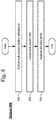
- Fig. 8 shows an exemplary method 800 for using shadows to segment occluded players.
- the segmentation may be accomplished by, in 810, extracting each player's shadow information.
- the shadows of each of the occluded players may be separable.
- the process of eliminating the shadow of a player inherently identifies the shadow of the player.
- this inherent identification of the player's shadow can be associated with the player in 810 and this can be performed for each player.
- each player's feet may be located using the shadow information extracted in 810. Exemplary manners of locating the player's feet using the shadow information has been described extensively above and any of these described methods may be used. It is also noted that in addition to the shadow information, other image information may also be used in conjunction with the shadow information to locate the player's feet. Again, this other information and its use in locating players' feet has been described above.
- the location of the feet of each player may then be used to guide known segmentation methods to segment out each player.
- the problem associated with the known segmentation methods is that when the location of the players' feet is not known with a high degree of accuracy, the segmentation methods have problems separating the various occluded players.
- the use of the shadow information allows for a highly accurate location of the players' feet to be determined. These accurate locations, in turn, allow for the segmentation methods (such as K-Means clustering methods) to more accurately separate the occluded players.
- known segmentation methods may better perform when the number of segments (e.g. players) and their relative locations in the blob to be segmented are given according to the exemplary embodiments.
- Fig. 9 shows a video image 900 from a football game that includes players' foregrounds and their shadows.
- the corresponding blob image 910 shows that there is severe occlusion and this demonstrates the difficulty in segmenting each player and estimating their locations.
- Fig. 10 shows a video image 1000 that identifies the shadow image projection of each player and the foreground image for each player, e.g., player image 1020 and shadow image projection 1030.
- the shadows provide valuable information with respect to how many players there are and how to separate the different players within the blob according to the exemplary embodiments discussed herein.
- the different players may be segmented out by a simple shadow-to-object association.
- the light source e.g. the sun
- the individual color patches may be associated with the corresponding player (e.g., the respective owner of a shadow).
- the pose can be roughly estimated based on the size, shape, or other features of the shadow. For instance, a crouching player will have a shorter shadow while a standing player will have a longer shadow.
- the real-world position of one or more of the light sources may be given or estimated based on analyses of the shadows. Accordingly, when a ball, puck, etc. casts a shadow on the ground, it is possible to estimate the 3D position of the ball, puck, etc., from a single frame of video captured by a single camera view using the detected position of the ball in the video image and the 2D position of its casted shadow on the ground. Additionally, or alternatively, using the 2D positions of two of the ball's casted shadows on the ground may also allow for the estimation of the 3D position of the ball from a single frame of video.
- the light sources e.g., arena lights, the sun, etc.
- Fig. 11 shows an exemplary model 1100 using the shadow information of an off the ground object 1110 (e.g. an in-air ball) to compute the 3D position of the object 1110 according to the exemplary embodiments discussed herein.
- the 3D position of the object 1110 may be derived through a single camera view based on the intersection between the projection lines, wherein a projection line is the line between a source of light and the respective shadow.
- the calculations used to compute the 3D position of the object 1110 will be apparent to those skilled in the art based on the data shown in Fig. 11 .
- the location of the object 1110 may be found based on the intersection between the projection line of one light source and the projection line of the camera (e.g., the line connecting the camera's center to the ball's image on the image plane).
- Fig. 12 shows an exemplary method 1200 for shadow assisted object recognition and tracking according to the exemplary embodiments discussed herein.
- the description of the method 1200 will provide an overview of these operations.
- all operations described in the entirety of this description may be optional, modified or performed in a different order, it is worth noting that this is also true for the operations that are described with reference to method 1200.
- an exemplary blob may be identified within a video image, wherein the blob includes a plurality of objects and at least one shadow.
- the blobs that are illustrated in image 600 of Fig. 6 or image 910 of Fig. 9 .
- shadow information pertaining to the at least one shadow may be analyzed and separated from the blob. As described above, this separating of the shadow image information from the object information may be used to process occluded objects and it may also be used to determine object location.
- the blob may be segmented into multiple image parts based on the shadow information. This operation is specifically for the occluded object segmentation operation which is described in detail with respect to Fig. 8 . If there are no occluded objects within the image, this operation does not necessarily need to be performed.
- the multiple image parts identified by the segmentation may be recognized and identified.
- a center position of one of the image parts may be determined based on the shadow information.
- the position of any distinguishable points within or along the boundary of one of the image parts may be determined based on the shadow information (e.g. tip of the elbows or knees).
- this location determination may be based solely on the shadow information or may also be based on additional information such as the camera information and light source information.
- the locating operation may be performed for the purposes of determining the location information as an ends to itself or may also be used as a location input to the segmentation methods that are performed in 1230.
- 3D positioning of a body part center e.g. head or feet
- 3D positioning of any desired location on the player's body may be computed according to the exemplary embodiments, as long as correspondence between the desired location at the player's image and the player's shadow may be established.
- the object e.g. , the player
- the object may be tracked from one frame to the next frame of the video based on the locations of the body parts or pose of the player that was previously determined.
- Fig. 13 shows an exemplary system 1300 for shadow assisted object recognition and tracking according to the exemplary embodiments discussed herein.
- the system 1300 may utilize a computing device 1310 to receive an input video 1380 to generate an enhanced video output 1390.
- the computing device 1310 may include an exemplary object recognition and tracking server 1320 that may include a processor 1330, a memory arrangement 1340, a display device 1350, an input/output ("I/O") device 1360, and other components 1370 (e.g., an audio input device, an audio output device, a battery, a data acquisition device, ports to electrically connect to other electronic devices, etc.).
- I/O input/output
- the exemplary processor 1330 may receive user input from the display 1350 or through other components of the device 1370 (e.g., keyboard, mouse, etc.).
- the exemplary memory 1340 may store instructions, including instructions related to the above-described software methods (e.g., method 800 of Fig. 8 or method 1200 of Fig. 12 ) and application (e.g., a shadow-assisted object recognition and tracking application), executable by the processor 1330. Therefore, a user of the computing device 1310 may interact with the software application stored in the memory 1340 of the computing device 1310.
- the processor 1330 may process these user interactions and adjust the content and modeling configurations.
- the exemplary processor 1330 may include, for example, a single processor, a multi-processor CPU/GPU, a cloud based computation system based on multiple computing devices, etc.
Landscapes
- Engineering & Computer Science (AREA)
- Physics & Mathematics (AREA)
- General Physics & Mathematics (AREA)
- Theoretical Computer Science (AREA)
- Computer Vision & Pattern Recognition (AREA)
- Computational Linguistics (AREA)
- Software Systems (AREA)
- Multimedia (AREA)
- Image Analysis (AREA)
- Length Measuring Devices By Optical Means (AREA)
Priority Applications (1)
| Application Number | Priority Date | Filing Date | Title |
|---|---|---|---|
| EP23210876.1A EP4358035A1 (de) | 2016-06-14 | 2017-06-14 | Vorrichtung, systeme und verfahren zur schattenunterstützten objekterkennung und -verfolgung |
Applications Claiming Priority (2)
| Application Number | Priority Date | Filing Date | Title |
|---|---|---|---|
| US201662350023P | 2016-06-14 | 2016-06-14 | |
| US15/456,987 US10438370B2 (en) | 2016-06-14 | 2017-03-13 | Apparatus, systems and methods for shadow assisted object recognition and tracking |
Related Child Applications (1)
| Application Number | Title | Priority Date | Filing Date |
|---|---|---|---|
| EP23210876.1A Division EP4358035A1 (de) | 2016-06-14 | 2017-06-14 | Vorrichtung, systeme und verfahren zur schattenunterstützten objekterkennung und -verfolgung |
Publications (1)
| Publication Number | Publication Date |
|---|---|
| EP3258421A1 true EP3258421A1 (de) | 2017-12-20 |
Family
ID=59077862
Family Applications (2)
| Application Number | Title | Priority Date | Filing Date |
|---|---|---|---|
| EP23210876.1A Pending EP4358035A1 (de) | 2016-06-14 | 2017-06-14 | Vorrichtung, systeme und verfahren zur schattenunterstützten objekterkennung und -verfolgung |
| EP17176057.2A Withdrawn EP3258421A1 (de) | 2016-06-14 | 2017-06-14 | Vorrichtung, systeme und verfahren zur schattenunterstützten objekterkennung und -verfolgung |
Family Applications Before (1)
| Application Number | Title | Priority Date | Filing Date |
|---|---|---|---|
| EP23210876.1A Pending EP4358035A1 (de) | 2016-06-14 | 2017-06-14 | Vorrichtung, systeme und verfahren zur schattenunterstützten objekterkennung und -verfolgung |
Country Status (4)
| Country | Link |
|---|---|
| US (2) | US10438370B2 (de) |
| EP (2) | EP4358035A1 (de) |
| BR (1) | BR102017012711A2 (de) |
| MX (1) | MX2017007724A (de) |
Families Citing this family (5)
| Publication number | Priority date | Publication date | Assignee | Title |
|---|---|---|---|---|
| JP7003994B2 (ja) * | 2017-08-08 | 2022-01-21 | ソニーグループ株式会社 | 画像処理装置および方法 |
| JP7003628B2 (ja) * | 2017-12-19 | 2022-01-20 | 富士通株式会社 | 物体追跡プログラム、物体追跡装置、及び物体追跡方法 |
| CN111274943B (zh) * | 2020-01-19 | 2023-06-23 | 深圳市商汤科技有限公司 | 一种检测方法、装置、电子设备及存储介质 |
| EP3913583A1 (de) * | 2020-05-19 | 2021-11-24 | Unity IPR APS | Verfahren und system zur filterung von schattenkarten mit unterrahmenansammlung |
| WO2022264010A1 (en) * | 2021-06-14 | 2022-12-22 | Omnieye Holdings Limited | Method and system for livestock monitoring and management |
Citations (4)
| Publication number | Priority date | Publication date | Assignee | Title |
|---|---|---|---|---|
| EP2385497A1 (de) * | 2010-05-03 | 2011-11-09 | Stats Llc | Bahnerkennung und Analyse bei Sportveranstaltungen |
| US20110304729A1 (en) * | 2010-06-11 | 2011-12-15 | Gianni Arcaini | Method for Automatically Ignoring Cast Self Shadows to Increase the Effectiveness of Video Analytics Based Surveillance Systems |
| WO2013032441A1 (en) * | 2011-08-30 | 2013-03-07 | Hewlett-Packard Development Company, L.P. | Inserting an object into an image |
| US20140118496A1 (en) * | 2012-10-31 | 2014-05-01 | Ricoh Company, Ltd. | Pre-Calculation of Sine Waves for Pixel Values |
Family Cites Families (5)
| Publication number | Priority date | Publication date | Assignee | Title |
|---|---|---|---|---|
| US8643717B2 (en) * | 2009-03-04 | 2014-02-04 | Hand Held Products, Inc. | System and method for measuring irregular objects with a single camera |
| EP2435789B1 (de) * | 2009-05-27 | 2015-04-08 | King Abdullah University Of Science And Technology | Mems-masse-feder-dämpfersysteme mit federungsschema ausserhalb der ebene |
| US8638989B2 (en) * | 2012-01-17 | 2014-01-28 | Leap Motion, Inc. | Systems and methods for capturing motion in three-dimensional space |
| US9600927B1 (en) * | 2012-10-21 | 2017-03-21 | Google Inc. | Systems and methods for capturing aspects of objects using images and shadowing |
| JP6037900B2 (ja) * | 2013-03-11 | 2016-12-07 | 日立マクセル株式会社 | 操作検出装置及び操作検出方法 |
-
2017
- 2017-03-13 US US15/456,987 patent/US10438370B2/en active Active
- 2017-06-13 MX MX2017007724A patent/MX2017007724A/es unknown
- 2017-06-14 EP EP23210876.1A patent/EP4358035A1/de active Pending
- 2017-06-14 EP EP17176057.2A patent/EP3258421A1/de not_active Withdrawn
- 2017-06-14 BR BR102017012711A patent/BR102017012711A2/pt unknown
-
2019
- 2019-09-20 US US16/577,000 patent/US10769810B2/en active Active
Patent Citations (4)
| Publication number | Priority date | Publication date | Assignee | Title |
|---|---|---|---|---|
| EP2385497A1 (de) * | 2010-05-03 | 2011-11-09 | Stats Llc | Bahnerkennung und Analyse bei Sportveranstaltungen |
| US20110304729A1 (en) * | 2010-06-11 | 2011-12-15 | Gianni Arcaini | Method for Automatically Ignoring Cast Self Shadows to Increase the Effectiveness of Video Analytics Based Surveillance Systems |
| WO2013032441A1 (en) * | 2011-08-30 | 2013-03-07 | Hewlett-Packard Development Company, L.P. | Inserting an object into an image |
| US20140118496A1 (en) * | 2012-10-31 | 2014-05-01 | Ricoh Company, Ltd. | Pre-Calculation of Sine Waves for Pixel Values |
Also Published As
| Publication number | Publication date |
|---|---|
| US20200013186A1 (en) | 2020-01-09 |
| US10438370B2 (en) | 2019-10-08 |
| MX2017007724A (es) | 2018-09-10 |
| US20170358104A1 (en) | 2017-12-14 |
| EP4358035A1 (de) | 2024-04-24 |
| BR102017012711A2 (pt) | 2018-10-30 |
| US10769810B2 (en) | 2020-09-08 |
Similar Documents
| Publication | Publication Date | Title |
|---|---|---|
| US10769810B2 (en) | Apparatus, systems and methods for shadow assisted object recognition and tracking | |
| US11064107B2 (en) | Objects trail-based analysis and control of video | |
| US8805007B2 (en) | Integrated background and foreground tracking | |
| JP6525453B2 (ja) | オブジェクト位置推定システム、及びそのプログラム | |
| Xu et al. | Architecture and algorithms for tracking football players with multiple cameras | |
| US8160302B2 (en) | Image processing apparatus and method for estimating orientation | |
| US8233721B2 (en) | Image processing apparatus and method | |
| CN108876821B (zh) | 跨镜头多目标跟踪方法及系统 | |
| US8547431B2 (en) | Method and apparatus for generating an event log | |
| Possegger et al. | Robust real-time tracking of multiple objects by volumetric mass densities | |
| JP2009064445A (ja) | 画像処理装置及び方法 | |
| Ren et al. | Multi-camera video surveillance for real-time analysis and reconstruction of soccer games | |
| JP2009077394A (ja) | 通信システム及び通信方法 | |
| KR101733116B1 (ko) | 고속 스테레오 카메라를 이용한 구형 물체의 비행 정보 측정 시스템 및 방법 | |
| Ren et al. | A general framework for 3D soccer ball estimation and tracking | |
| US11798233B2 (en) | Generation device, generation method and storage medium for three-dimensional model that remove a portion of the three-dimensional model | |
| Liu et al. | A novel approach for tracking high speed skaters in sports using a panning camera | |
| US11514678B2 (en) | Data processing method and apparatus for capturing and analyzing images of sporting events | |
| Liu et al. | Hierarchical model-based human motion tracking via unscented Kalman filter | |
| Kasuya et al. | Robust trajectory estimation of soccer players by using two cameras | |
| Yu | Automatic basketball tracking in broadcast basketball video | |
| Evans et al. | Automatic high fidelity foot contact location and timing for elite sprinting | |
| WO2023061356A1 (zh) | 广告投放方法、装置、设备、存储介质和计算机程序产品 | |
| Kataoka et al. | Football players and ball trajectories projection from single camera's image | |
| Liu et al. | Human Motion Tracking Based on Unscented Kalman Filter in Sports Domain |
Legal Events
| Date | Code | Title | Description |
|---|---|---|---|
| PUAI | Public reference made under article 153(3) epc to a published international application that has entered the european phase |
Free format text: ORIGINAL CODE: 0009012 |
|
| STAA | Information on the status of an ep patent application or granted ep patent |
Free format text: STATUS: REQUEST FOR EXAMINATION WAS MADE |
|
| 17P | Request for examination filed |
Effective date: 20170614 |
|
| AK | Designated contracting states |
Kind code of ref document: A1 Designated state(s): AL AT BE BG CH CY CZ DE DK EE ES FI FR GB GR HR HU IE IS IT LI LT LU LV MC MK MT NL NO PL PT RO RS SE SI SK SM TR |
|
| AX | Request for extension of the european patent |
Extension state: BA ME |
|
| STAA | Information on the status of an ep patent application or granted ep patent |
Free format text: STATUS: EXAMINATION IS IN PROGRESS |
|
| 17Q | First examination report despatched |
Effective date: 20200331 |
|
| STAA | Information on the status of an ep patent application or granted ep patent |
Free format text: STATUS: EXAMINATION IS IN PROGRESS |
|
| P01 | Opt-out of the competence of the unified patent court (upc) registered |
Effective date: 20230525 |
|
| STAA | Information on the status of an ep patent application or granted ep patent |
Free format text: STATUS: THE APPLICATION HAS BEEN WITHDRAWN |
|
| 18W | Application withdrawn |
Effective date: 20231120 |