EP3258258B1 - Peau sensorielle - Google Patents
Peau sensorielle Download PDFInfo
- Publication number
- EP3258258B1 EP3258258B1 EP16174250.7A EP16174250A EP3258258B1 EP 3258258 B1 EP3258258 B1 EP 3258258B1 EP 16174250 A EP16174250 A EP 16174250A EP 3258258 B1 EP3258258 B1 EP 3258258B1
- Authority
- EP
- European Patent Office
- Prior art keywords
- component
- sensors
- flexible substrate
- substrate
- measuring device
- Prior art date
- Legal status (The legal status is an assumption and is not a legal conclusion. Google has not performed a legal analysis and makes no representation as to the accuracy of the status listed.)
- Active
Links
- 239000000758 substrate Substances 0.000 claims description 53
- 238000004519 manufacturing process Methods 0.000 claims description 25
- 238000000034 method Methods 0.000 claims description 22
- 230000008569 process Effects 0.000 claims description 14
- 239000011159 matrix material Substances 0.000 claims description 12
- 229920002430 Fibre-reinforced plastic Polymers 0.000 claims description 11
- 239000011151 fibre-reinforced plastic Substances 0.000 claims description 11
- 238000005259 measurement Methods 0.000 claims description 8
- 238000012545 processing Methods 0.000 claims description 6
- 229920000106 Liquid crystal polymer Polymers 0.000 claims description 4
- 239000004977 Liquid-crystal polymers (LCPs) Substances 0.000 claims description 4
- 239000004695 Polyether sulfone Substances 0.000 claims description 2
- 239000004697 Polyetherimide Substances 0.000 claims description 2
- 239000004642 Polyimide Substances 0.000 claims description 2
- 239000004020 conductor Substances 0.000 claims description 2
- 229920002492 poly(sulfone) Polymers 0.000 claims description 2
- 229920006393 polyether sulfone Polymers 0.000 claims description 2
- 229920001601 polyetherimide Polymers 0.000 claims description 2
- 229920001721 polyimide Polymers 0.000 claims description 2
- 229920006258 high performance thermoplastic Polymers 0.000 claims 2
- 239000010408 film Substances 0.000 description 10
- 230000032798 delamination Effects 0.000 description 7
- 229920003023 plastic Polymers 0.000 description 7
- 239000004033 plastic Substances 0.000 description 7
- 238000012544 monitoring process Methods 0.000 description 6
- 238000011161 development Methods 0.000 description 5
- 230000018109 developmental process Effects 0.000 description 5
- 239000000463 material Substances 0.000 description 5
- 229920001169 thermoplastic Polymers 0.000 description 4
- 239000004416 thermosoftening plastic Substances 0.000 description 4
- 239000000853 adhesive Substances 0.000 description 3
- 230000001070 adhesive effect Effects 0.000 description 3
- 238000006243 chemical reaction Methods 0.000 description 3
- 230000010354 integration Effects 0.000 description 3
- 238000000465 moulding Methods 0.000 description 3
- 238000013459 approach Methods 0.000 description 2
- 238000009529 body temperature measurement Methods 0.000 description 2
- 239000004918 carbon fiber reinforced polymer Substances 0.000 description 2
- 239000000919 ceramic Substances 0.000 description 2
- 230000008859 change Effects 0.000 description 2
- 238000013461 design Methods 0.000 description 2
- 238000012423 maintenance Methods 0.000 description 2
- 238000002604 ultrasonography Methods 0.000 description 2
- 235000019687 Lamb Nutrition 0.000 description 1
- 238000010521 absorption reaction Methods 0.000 description 1
- 238000007792 addition Methods 0.000 description 1
- 238000005137 deposition process Methods 0.000 description 1
- 238000001514 detection method Methods 0.000 description 1
- 238000005516 engineering process Methods 0.000 description 1
- 238000011156 evaluation Methods 0.000 description 1
- 239000003365 glass fiber Substances 0.000 description 1
- 238000002347 injection Methods 0.000 description 1
- 239000007924 injection Substances 0.000 description 1
- 238000007689 inspection Methods 0.000 description 1
- 230000004807 localization Effects 0.000 description 1
- 230000008439 repair process Effects 0.000 description 1
- 239000011347 resin Substances 0.000 description 1
- 229920005989 resin Polymers 0.000 description 1
- 230000001953 sensory effect Effects 0.000 description 1
- 239000007787 solid Substances 0.000 description 1
- 238000012360 testing method Methods 0.000 description 1
- 239000010409 thin film Substances 0.000 description 1
Images
Classifications
-
- G—PHYSICS
- G01—MEASURING; TESTING
- G01N—INVESTIGATING OR ANALYSING MATERIALS BY DETERMINING THEIR CHEMICAL OR PHYSICAL PROPERTIES
- G01N29/00—Investigating or analysing materials by the use of ultrasonic, sonic or infrasonic waves; Visualisation of the interior of objects by transmitting ultrasonic or sonic waves through the object
- G01N29/04—Analysing solids
-
- B—PERFORMING OPERATIONS; TRANSPORTING
- B32—LAYERED PRODUCTS
- B32B—LAYERED PRODUCTS, i.e. PRODUCTS BUILT-UP OF STRATA OF FLAT OR NON-FLAT, e.g. CELLULAR OR HONEYCOMB, FORM
- B32B27/00—Layered products comprising a layer of synthetic resin
- B32B27/06—Layered products comprising a layer of synthetic resin as the main or only constituent of a layer, which is next to another layer of the same or of a different material
-
- B—PERFORMING OPERATIONS; TRANSPORTING
- B32—LAYERED PRODUCTS
- B32B—LAYERED PRODUCTS, i.e. PRODUCTS BUILT-UP OF STRATA OF FLAT OR NON-FLAT, e.g. CELLULAR OR HONEYCOMB, FORM
- B32B27/00—Layered products comprising a layer of synthetic resin
- B32B27/28—Layered products comprising a layer of synthetic resin comprising synthetic resins not wholly covered by any one of the sub-groups B32B27/30 - B32B27/42
- B32B27/281—Layered products comprising a layer of synthetic resin comprising synthetic resins not wholly covered by any one of the sub-groups B32B27/30 - B32B27/42 comprising polyimides
-
- B—PERFORMING OPERATIONS; TRANSPORTING
- B32—LAYERED PRODUCTS
- B32B—LAYERED PRODUCTS, i.e. PRODUCTS BUILT-UP OF STRATA OF FLAT OR NON-FLAT, e.g. CELLULAR OR HONEYCOMB, FORM
- B32B27/00—Layered products comprising a layer of synthetic resin
- B32B27/28—Layered products comprising a layer of synthetic resin comprising synthetic resins not wholly covered by any one of the sub-groups B32B27/30 - B32B27/42
- B32B27/286—Layered products comprising a layer of synthetic resin comprising synthetic resins not wholly covered by any one of the sub-groups B32B27/30 - B32B27/42 comprising polysulphones; polysulfides
-
- B—PERFORMING OPERATIONS; TRANSPORTING
- B32—LAYERED PRODUCTS
- B32B—LAYERED PRODUCTS, i.e. PRODUCTS BUILT-UP OF STRATA OF FLAT OR NON-FLAT, e.g. CELLULAR OR HONEYCOMB, FORM
- B32B5/00—Layered products characterised by the non- homogeneity or physical structure, i.e. comprising a fibrous, filamentary, particulate or foam layer; Layered products characterised by having a layer differing constitutionally or physically in different parts
- B32B5/02—Layered products characterised by the non- homogeneity or physical structure, i.e. comprising a fibrous, filamentary, particulate or foam layer; Layered products characterised by having a layer differing constitutionally or physically in different parts characterised by structural features of a fibrous or filamentary layer
- B32B5/10—Layered products characterised by the non- homogeneity or physical structure, i.e. comprising a fibrous, filamentary, particulate or foam layer; Layered products characterised by having a layer differing constitutionally or physically in different parts characterised by structural features of a fibrous or filamentary layer characterised by a fibrous or filamentary layer reinforced with filaments
-
- G—PHYSICS
- G01—MEASURING; TESTING
- G01N—INVESTIGATING OR ANALYSING MATERIALS BY DETERMINING THEIR CHEMICAL OR PHYSICAL PROPERTIES
- G01N29/00—Investigating or analysing materials by the use of ultrasonic, sonic or infrasonic waves; Visualisation of the interior of objects by transmitting ultrasonic or sonic waves through the object
- G01N29/04—Analysing solids
- G01N29/043—Analysing solids in the interior, e.g. by shear waves
-
- G—PHYSICS
- G01—MEASURING; TESTING
- G01N—INVESTIGATING OR ANALYSING MATERIALS BY DETERMINING THEIR CHEMICAL OR PHYSICAL PROPERTIES
- G01N29/00—Investigating or analysing materials by the use of ultrasonic, sonic or infrasonic waves; Visualisation of the interior of objects by transmitting ultrasonic or sonic waves through the object
- G01N29/22—Details, e.g. general constructional or apparatus details
- G01N29/24—Probes
- G01N29/2406—Electrostatic or capacitive probes, e.g. electret or cMUT-probes
-
- G—PHYSICS
- G01—MEASURING; TESTING
- G01N—INVESTIGATING OR ANALYSING MATERIALS BY DETERMINING THEIR CHEMICAL OR PHYSICAL PROPERTIES
- G01N29/00—Investigating or analysing materials by the use of ultrasonic, sonic or infrasonic waves; Visualisation of the interior of objects by transmitting ultrasonic or sonic waves through the object
- G01N29/22—Details, e.g. general constructional or apparatus details
- G01N29/24—Probes
- G01N29/2437—Piezoelectric probes
-
- B—PERFORMING OPERATIONS; TRANSPORTING
- B32—LAYERED PRODUCTS
- B32B—LAYERED PRODUCTS, i.e. PRODUCTS BUILT-UP OF STRATA OF FLAT OR NON-FLAT, e.g. CELLULAR OR HONEYCOMB, FORM
- B32B2307/00—Properties of the layers or laminate
- B32B2307/20—Properties of the layers or laminate having particular electrical or magnetic properties, e.g. piezoelectric
-
- B—PERFORMING OPERATIONS; TRANSPORTING
- B32—LAYERED PRODUCTS
- B32B—LAYERED PRODUCTS, i.e. PRODUCTS BUILT-UP OF STRATA OF FLAT OR NON-FLAT, e.g. CELLULAR OR HONEYCOMB, FORM
- B32B2379/00—Other polymers having nitrogen, with or without oxygen or carbon only, in the main chain
- B32B2379/08—Polyimides
-
- B—PERFORMING OPERATIONS; TRANSPORTING
- B32—LAYERED PRODUCTS
- B32B—LAYERED PRODUCTS, i.e. PRODUCTS BUILT-UP OF STRATA OF FLAT OR NON-FLAT, e.g. CELLULAR OR HONEYCOMB, FORM
- B32B2457/00—Electrical equipment
-
- G—PHYSICS
- G01—MEASURING; TESTING
- G01N—INVESTIGATING OR ANALYSING MATERIALS BY DETERMINING THEIR CHEMICAL OR PHYSICAL PROPERTIES
- G01N2291/00—Indexing codes associated with group G01N29/00
- G01N2291/02—Indexing codes associated with the analysed material
- G01N2291/023—Solids
- G01N2291/0231—Composite or layered materials
-
- G—PHYSICS
- G01—MEASURING; TESTING
- G01N—INVESTIGATING OR ANALYSING MATERIALS BY DETERMINING THEIR CHEMICAL OR PHYSICAL PROPERTIES
- G01N2291/00—Indexing codes associated with group G01N29/00
- G01N2291/02—Indexing codes associated with the analysed material
- G01N2291/023—Solids
- G01N2291/0235—Plastics; polymers; soft materials, e.g. rubber
-
- G—PHYSICS
- G01—MEASURING; TESTING
- G01N—INVESTIGATING OR ANALYSING MATERIALS BY DETERMINING THEIR CHEMICAL OR PHYSICAL PROPERTIES
- G01N2291/00—Indexing codes associated with group G01N29/00
- G01N2291/02—Indexing codes associated with the analysed material
- G01N2291/028—Material parameters
- G01N2291/0289—Internal structure, e.g. defects, grain size, texture
-
- G—PHYSICS
- G01—MEASURING; TESTING
- G01N—INVESTIGATING OR ANALYSING MATERIALS BY DETERMINING THEIR CHEMICAL OR PHYSICAL PROPERTIES
- G01N2291/00—Indexing codes associated with group G01N29/00
- G01N2291/10—Number of transducers
- G01N2291/106—Number of transducers one or more transducer arrays
-
- G—PHYSICS
- G01—MEASURING; TESTING
- G01N—INVESTIGATING OR ANALYSING MATERIALS BY DETERMINING THEIR CHEMICAL OR PHYSICAL PROPERTIES
- G01N2291/00—Indexing codes associated with group G01N29/00
- G01N2291/26—Scanned objects
- G01N2291/269—Various geometry objects
- G01N2291/2694—Wings or other aircraft parts
Definitions
- the invention relates to a system comprising a component made of at least one fiber-reinforced plastic and a measuring system with a plurality of sensors which are arranged at a distance from one another on the component, wherein the sensors are distributed over a curved surface of the component, wherein the component is provided with a substrate external to the component on which the sensors are arranged, wherein the substrate is flexible, and wherein the sensors arranged on the flexible substrate form a measuring device.
- measuring systems are known whose sensors can be attached to a component made of fiber-reinforced plastic.
- the sensors In order to be able to reliably assess, for example, future damage with reasonable spatial resolution using a measuring system on such components, the sensors must be arranged in the appropriate number on the corresponding surface, which involves a great deal of effort. If, in addition, one wants to make statements about the manufacturing process of the component as well as about interference factors occurring during its operation based on sensor recordings, the above-mentioned effort may even have to be made several times. The effort required for the associated measuring equipment, for example for signal processing, also increases to the same extent.
- a measuring device in the form of a plurality of sensors is arranged on a flexible substrate, which forms a suitable film made of a thermoplastic high-performance plastic, and is integrated into the component during manufacture, and the substrate is arranged particularly reliably on the component, with the flexible substrate forming a material bond with the matrix during manufacture of the component.
- the component is given an additional ability, namely that of monitoring both process parameters during manufacture and the influence of potentially harmful events on their structural integrity during operation, with reasonable effort, cost-effectively and reliably, so that the corresponding data is basically available at any time.
- the flexible substrate provided with the sensors forms a kind of sensor skin.
- the curvature of the surface that forms the sensor skin is to be understood in the Gaussian sense, so that in an extreme case a surface with vanishing Gaussian curvature forms a subgroup of a torso, namely a plane.
- the sensor skin with the flexible substrate is arranged on a component surface.
- the measuring device with its sensors can be designed to monitor the manufacturing process, the occurrence of damage during operation of the component or even both processes, so that, based on corresponding state variables, potential values can be obtained from the creation of the component up to the occurrence of damage.
- the majority of sensors of the measuring device can be designed as ultrasonic transducers, so that with these sensors a whole range of established measuring methods are available in order to be able to determine a structural change in the component in question.
- the term sensor is to be understood both in its actual literal sense and in the sense of a sensor/actuator arrangement, i.e. a transducer, with which a signal can be both recorded and generated.
- various conversion principles are then also available with which, in the case of an ultrasonic measuring method, acoustic signals can be converted into electrical signals, namely, for example, the electrostatic, the piezoelectric or the piezoresistive conversion principle.
- transducers with different conversion principles are also conceivable.
- CMUT Capacitive micromachined ultrasonic transducers
- CMUT Capacitive micromachined ultrasonic transducers
- CMUT are micromechanical structures that can be used to generate and receive acoustic signals in the ultrasonic range. They can be used to create high-quality, miniaturized ultrasonic transmitters/receivers that can be easily integrated into CMOS circuits. can be integrated and are resistant to high temperatures.
- the use of thin layers applied by means of a deposition process also allows the targeted application of the piezoelectricity of certain materials for the production of miniaturized systems with both sensory and actuator properties
- the sensors can also be advantageous if some of the sensors are designed as temperature sensors, so that damage monitoring can also take place based on temperature measurements, for example as a resistance temperature measurement using four-wire measurement technology. If necessary, this can be used to check the measurements with other types of sensors.
- delaminations on the respective component can advantageously be detected by ultrasound using a pulse-echo method that is easy to control and delivers reliable results.
- a time delay of a signal is measured, with any delaminations that may occur in the structure of the component reducing this time delay. It is also possible to measure the change in amplitude instead. Other methods are also possible, such as the use of Lamb waves.
- CMUT capacitive micromechanic ultrasonic transducers can be used as micromechanical structures for generating and receiving acoustic signals in the ultrasonic range.
- the measuring device is provided on the flexible substrate in its two flat extension directions with a matrix of sensors that are evenly spaced in these directions, in particular with an identical distance in both directions, so that a sufficiently high sensor density can be achieved.
- the sensor density can particularly preferably be approximately in the order of magnitude of an expected damage event in the form of, for example, delamination.
- other distances that do not fit into any of the dimensions necessarily have to exhibit some kind of uniformity.
- conductor tracks, multiplexers or other electronic devices can be conveniently applied and integrated on the flexible substrate.
- multiplexers, a signal processing unit and a so-called analog front end can be arranged on the flexible substrate via circuit integration, whereby the latter can contain transmitters, receivers, amplifiers and filters as well as digitizers. Overall, the majority of the signal processing equipment is already integrated on the substrate connected to the component.
- the substrate in the measuring system forms a sensor film and is made of a thermoplastic high-performance plastic.
- the substrate in question can be connected to the component matrix during its manufacture.
- the flexible substrate can be connected or bonded to the component using a co-bonding or co-curing process.
- the material bond between the flexible substrate and the component matrix preferably takes place either by hard-in-wet bonding (co-bonding) or wet-in-wet bonding (co-curing), i.e. processes in which at least one of the joining partners has not yet hardened, so that a reliable structural connection between the substrate and the component matrix is achieved with low tolerances.
- the flexible substrate can also be integrated between the structural elements using such a process when joining several structural elements to form an overall component.
- thermoplastic high-performance plastic is made of a polyimide, in particular polyethrimide, or a polysulfone, in particular polyethersulfone.
- the adhesive used can be adapted in such a way that it serves to adapt the impedance for an ultrasound measurement, i.e. to adapt the acoustic impedance difference between the various solid bodies, so that an improved signal-to-noise ratio can be achieved.
- the substrate with the Structures are provided with at least one additional layer, in particular a mechanically and/or electrically insulating layer.
- LCP liquid crystal polymer
- a sensor arrangement on a curved surface of a component made of a fiber-reinforced plastic is disclosed herein, wherein the sensor arrangement is formed on a flexible substrate made of a thermoplastic high-performance plastic, which was bonded to the matrix of the component during its manufacture.
- the service life of the electronic components integrated on the sensor film is reduced too much by the high temperature prevailing during CFRP component production or if the electronic components are damaged, they can also be subsequently applied and/or replaced.
- This can be advantageously simplified in the invention by providing interposers onto which the electronic chips can be plugged. This allows the distances between the contact elements to be handled more flexibly, which leads to a more robust production process.
- one or more interposer structures are arranged on the substrate, which can be equipped with sensors after completion of the component production.
- a film with a high sensor density and integrated electronic functionality which is integrated into a component to be monitored, can take over both process monitoring for the production of fiber-reinforced plastic parts and damage detection during operation.
- This means that a single system can be used for process monitoring and damage selection, whereby thanks to integrated electronics, essentially No cabling effort is required at all, and by using an established method (pulse echo method) simple signal evaluation and damage localization is possible.
- the measuring system provided according to the invention also enables component self-monitoring, which replaces inspections and extends maintenance intervals or, in some cases, makes them obsolete. It is also conceivable that it could be used in the areas of retrofit/repair for maintenance and servicing, particularly for aerospace components.
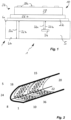
- the Figure 1 shows a measuring system, designated as a whole by 1, for determining damage to a component 5 made of a fiber-reinforced plastic.
- a film made of a flexible substrate 22 is arranged as a sensor skin 20 on the upper side of the component 5 for the observer.
- This sensor skin 20 is provided with a plurality of sensors 24 which form a measuring device 10 on the substrate 22.
- the sensors 24 are formed by transducers arranged on the flexible substrate 22 made of a polyetherimide. These in turn consist of two electrodes 26a, 26b lying opposite one another, between which a piezoelectric ceramic film 28 is arranged.
- This arrangement of transducers as sensors 24 forms the sensor skin 20 on the flexible substrate 22, which is arranged on a surface of the component 5.
- the sensors 24 are used to carry out a pulse-echo method on the component 5 to detect damage, which is shown by the ultrasonic waves running back and forth between two opposite side surfaces 6a, 6b of the component 5, which are indicated by arrows 32a, 32b, 33a, 33b.
- the left area of the Figure 1 one can see sound waves 32a, 32b running back and forth unhindered between the side surfaces 6a, 6b, while in the right-hand area their running time is shortened by the fact that the sound waves 33a, 33b encounter a delamination 34 on their way through the plastic component 5 and are already reflected there.
- the signal processing already largely takes place on the sensor skin 20 is due to electronic devices 36 which are applied and integrated on the flexible substrate 22, as can be seen in the Figure 2 can be recognized.
- Its parabolic profile 16 is provided with a plurality of sensor skins 20 on its inner side.
- the sensor skins 20 each clearly form a curved surface on the inner side of the wing profile 16.
- sensors 24 can be seen that are evenly distributed over the respective surface and can carry out ultrasonic measurements on the glass fiber reinforced component 5.
- the permanent connection between the sensor skins 20 and the component 5 achieved in the previous manufacturing process ensures uninterrupted monitoring of the structural integrity of the component 5 in question and the associated signal processing.
- the invention described above relates to a measuring system 1 for determining damage to components 5 made of at least one fiber-reinforced plastic with a plurality of sensors 24 which are arranged at a distance from one another on a component 5, wherein the sensors 24 are distributed over a curved surface of the component 5 in the position of use.
- the component 5 is provided with a substrate 22 that is external to the component and on which the sensors 24 are arranged, wherein the substrate 22 is flexible and the sensors 24 arranged on the flexible substrate 22 form a measuring device 10.
- the flexible substrate 22 also forms a material bond with the matrix of the component 5 during the manufacture of the component.
Landscapes
- Physics & Mathematics (AREA)
- Health & Medical Sciences (AREA)
- Life Sciences & Earth Sciences (AREA)
- Chemical & Material Sciences (AREA)
- Analytical Chemistry (AREA)
- Biochemistry (AREA)
- General Health & Medical Sciences (AREA)
- General Physics & Mathematics (AREA)
- Immunology (AREA)
- Pathology (AREA)
- Acoustics & Sound (AREA)
- Investigating Or Analyzing Materials By The Use Of Ultrasonic Waves (AREA)
Claims (13)
- Système présentant un composant (5) d'au moins une matière plastique renforcée par des fibres, et un système de mesure (1) pourvu d'une pluralité de capteurs (24) qui sont disposés sur le composant (5) de manière espacée les uns des autres, dans lequel les capteurs (24) sont répartis sur une surface courbe du composant (5), dans lequel le composant (5) est muni d'un substrat (22) externe au composant et sur lequel sont disposés les capteurs (24), dans lequel le substrat (22) est réalisé de manière flexible, les capteurs (24) disposés sur le substrat flexible (22) forment un dispositif de mesure (10), et le substrat flexible (22) muni des capteurs (24) forme une peau sensorielle (20), dans lequel le substrat flexible (22) forme un film qui est formé par une matière thermoplastique haute performance, caractérisé en ce que lors de la fabrication du composant (5), le substrat flexible (22) crée un assemblage par liaison de matière avec la matrice de celui-ci, et le substrat flexible (22) relié à la matrice du composant (5) est disposé sur la surface de celui-ci, dans lequel des moyens de traitement de signal sont prévus sur la peau sensorielle (20), et dans lequel une ou plusieurs structures d'interposition sont disposées sur le substrat (22).
- Système selon la revendication 1, caractérisé en ce que le dispositif de mesure (10) est conçu pour surveiller par ses capteurs (24) le processus de fabrication et/ou le fonctionnement du composant (5).
- Système selon l'une quelconque des revendications précédentes, caractérisé en ce que la pluralité de capteurs (24) du dispositif de mesure (10) est réalisée sur le substrat flexible (22) sous forme de transducteur à ultrasons.
- Système selon la revendication 3, caractérisé en ce que les transducteurs à ultrasons sont réalisés sous forme de transducteurs à ultrasons capacitifs fabriqués de manière micromécanique ou sont réalisés sous forme de couche mince piézoélectrique.
- Système selon l'une quelconque des revendications précédentes, caractérisé en ce que le dispositif de mesure (10) est conçu pour effectuer un procédé à impulsion/ par écho.
- Système selon l'une quelconque des revendications précédentes, caractérisé en ce que le dispositif de mesure (10) est conçu pour effectuer une mesure capacitive au moyen des capteurs (24).
- Système selon l'une quelconque des revendications précédentes, caractérisé en ce que le dispositif de mesure (10) forme sur le substrat (22) dans ses deux directions d'extension planes une matrice de capteurs (24) respectivement espacés de manière régulière dans ces directions, en particulier des capteurs (24) disposés à distance identique dans les deux directions.
- Système selon l'une quelconque des revendications précédentes, caractérisé en ce que des pistes conductrices, des multiplexeurs ou d'autres dispositifs électroniques (36) sont appliqués et intégrés sur le substrat flexible (22).
- Système selon l'une quelconque des revendications précédentes, caractérisé en ce que le substrat flexible (22) peut être ou est relié au composant par un processus de co-liaison ou de co-durcissement.
- Système selon l'une quelconque des revendications précédentes, caractérisé en ce que la matière thermoplastique haute performance est formée à partir d'un polyimide, en particulier d'un polyétherimide, ou d'un polysulfone, en particulier d'un polyéthersulfone.
- Système selon l'une quelconque des revendications précédentes, caractérisé en ce que des structures appliquées sur le substrat flexible (22) peuvent être ou sont protégées par rapport à leur environnement par au moins une couche disposée en plus.
- Système selon l'une quelconque des revendications précédentes, caractérisé en ce que le substrat flexible et/ou la couche disposée en plus sont réalisés sous forme de polymère à cristaux liquides (LCP).
- Système selon l'une quelconque des revendications précédentes, caractérisé en ce que ladite une ou les plusieurs structures d'interposition sont garnies de capteurs après la fin de la fabrication du composant.
Priority Applications (2)
| Application Number | Priority Date | Filing Date | Title |
|---|---|---|---|
| EP16174250.7A EP3258258B1 (fr) | 2016-06-13 | 2016-06-13 | Peau sensorielle |
| US15/610,567 US10830736B2 (en) | 2016-06-13 | 2017-05-31 | Sensor skin |
Applications Claiming Priority (1)
| Application Number | Priority Date | Filing Date | Title |
|---|---|---|---|
| EP16174250.7A EP3258258B1 (fr) | 2016-06-13 | 2016-06-13 | Peau sensorielle |
Publications (2)
| Publication Number | Publication Date |
|---|---|
| EP3258258A1 EP3258258A1 (fr) | 2017-12-20 |
| EP3258258B1 true EP3258258B1 (fr) | 2024-07-31 |
Family
ID=56413467
Family Applications (1)
| Application Number | Title | Priority Date | Filing Date |
|---|---|---|---|
| EP16174250.7A Active EP3258258B1 (fr) | 2016-06-13 | 2016-06-13 | Peau sensorielle |
Country Status (2)
| Country | Link |
|---|---|
| US (1) | US10830736B2 (fr) |
| EP (1) | EP3258258B1 (fr) |
Families Citing this family (1)
| Publication number | Priority date | Publication date | Assignee | Title |
|---|---|---|---|---|
| EP4067053A1 (fr) | 2021-04-01 | 2022-10-05 | Université de Rennes 1 | Procédé de fabrication d'un matériau composite comprenant au moins un élément électronique et matériau composite ainsi obtenu |
Citations (3)
| Publication number | Priority date | Publication date | Assignee | Title |
|---|---|---|---|---|
| US20080100587A1 (en) * | 2006-03-27 | 2008-05-01 | Sanyo Electric Co., Ltd. | Touch sensor, touch pad and input device |
| US20080309200A1 (en) * | 2005-11-29 | 2008-12-18 | Dolphiscan As | Ultrasonic Transducer Module Comprising a Transmitter Layer and a Receiver Layer |
| US20130192356A1 (en) * | 2009-10-01 | 2013-08-01 | Mc10, Inc. | Methods and apparatus for measuring technical parameters of equipment, tools, and components via conformal electronics |
Family Cites Families (8)
| Publication number | Priority date | Publication date | Assignee | Title |
|---|---|---|---|---|
| EP0671221B1 (fr) * | 1994-03-11 | 2000-04-26 | Intravascular Research Limited | Réseau de transducteurs à ultrason et son procédé de fabrication |
| EP1907133A4 (fr) * | 2005-06-17 | 2012-05-09 | Kolo Technologies Inc | Transducteur microelectromecanique presentant une extension d'isolation |
| FR2901610B1 (fr) * | 2006-05-24 | 2009-01-16 | Airbus France Sas | Dispositif de controle non destructif d'une struture par analyse vibratoire |
| WO2010140638A1 (fr) * | 2009-06-05 | 2010-12-09 | 古河電気工業株式会社 | Stratifié revêtu de métal et son procédé de fabrication |
| US9511393B2 (en) * | 2012-08-17 | 2016-12-06 | The Boeing Company | Flexible ultrasound inspection system |
| US20150078136A1 (en) * | 2013-09-13 | 2015-03-19 | Mitsubishi Heavy Industries, Ltd. | Conformable Transducer With Self Position Sensing |
| KR20170019408A (ko) * | 2014-06-10 | 2017-02-21 | 쓰리엠 이노베이티브 프로퍼티즈 컴파니 | Uv 차단성을 갖는 가요성 led 조립체 |
| US10583616B2 (en) * | 2014-06-20 | 2020-03-10 | The Boeing Company | Forming tools and flexible ultrasonic transducer arrays |
-
2016
- 2016-06-13 EP EP16174250.7A patent/EP3258258B1/fr active Active
-
2017
- 2017-05-31 US US15/610,567 patent/US10830736B2/en active Active
Patent Citations (3)
| Publication number | Priority date | Publication date | Assignee | Title |
|---|---|---|---|---|
| US20080309200A1 (en) * | 2005-11-29 | 2008-12-18 | Dolphiscan As | Ultrasonic Transducer Module Comprising a Transmitter Layer and a Receiver Layer |
| US20080100587A1 (en) * | 2006-03-27 | 2008-05-01 | Sanyo Electric Co., Ltd. | Touch sensor, touch pad and input device |
| US20130192356A1 (en) * | 2009-10-01 | 2013-08-01 | Mc10, Inc. | Methods and apparatus for measuring technical parameters of equipment, tools, and components via conformal electronics |
Also Published As
| Publication number | Publication date |
|---|---|
| US10830736B2 (en) | 2020-11-10 |
| EP3258258A1 (fr) | 2017-12-20 |
| US20170356883A1 (en) | 2017-12-14 |
Similar Documents
| Publication | Publication Date | Title |
|---|---|---|
| EP3194831B1 (fr) | Capteur capacitif | |
| EP0936447B1 (fr) | Matériau en polymère et procédé de fabrication, système et procédé pour le contrôle de matériaux en polymère et d'éléments de construction | |
| DE10325406A1 (de) | Schadensermittlung an zu prüfenden Strukturen mittels Ultraschall | |
| EP2657801A2 (fr) | Surveillance d'un processus de fabrication | |
| EP3418736B1 (fr) | Procédé et dispositif de mesure de bande de largeur à l'aide d'un transducteur d'ultra-sons d'air multiélémentaire | |
| EP2930508B1 (fr) | Procédé de vérification de composants par ultrasons et dispositif de vérification avec un manipulateur | |
| EP3258258B1 (fr) | Peau sensorielle | |
| DE102018131948B4 (de) | Verfahren und Vorrichtung zum Detektieren eines Schlagereignisses sowie ein Fahrzeug hierzu | |
| DE4025564C1 (en) | Impact damage registering appts. for laminated fibre components - uses piezoelectric foil pieces distributed over component and connected to monitor to ascertain changes in capacitative charge | |
| DE102011122481B4 (de) | Verfahren und Anordnung zur Überwachung und Lokalisierung von Materialschäden und Diskontinuitäten in Leichtbau-Verbundstrukturen | |
| EP2534466B1 (fr) | Système de détection pour déterminer la fatigue de pièces de construction métalliques | |
| EP3258230B1 (fr) | Peau sensorielle avec sonde de temperature | |
| DE202016004465U1 (de) | Sensorhaut | |
| WO2022008190A1 (fr) | Dispositif mems avec élément capteur tactile et élément capteur de proximité | |
| WO2022122490A1 (fr) | Système de capteur ultrasonore pour un véhicule à moteur et procédé de fonctionnement du système de capteur ultrasonore | |
| DE102020105779A1 (de) | Vorrichtung zum Überwachen eines Herstellungsprozesses zur Herstellung eines Faserverbundbauteils | |
| DE102019134544A1 (de) | Verfahren und System zur Überprüfung einer Klebverbindung | |
| DE102006010009A1 (de) | Verfahren zum Herstellen eines Ultraschallprüfkopfes mit einer Ultraschallwandleranordnung mit einer gekrümmten Sende- und Empfangsfläche | |
| EP3535574A1 (fr) | Pièce moulée constituée de composite renforcé de fibres | |
| DE102004043181B3 (de) | Sensoranordnung und Verfahren zur Detektion des Einflusses von auf Konstruktionselementen wirkenden statischen und dynamischen Belastungen | |
| EP3444605A1 (fr) | Microphone à ultrasons pourvu de test intégré | |
| WO2017108235A1 (fr) | Procédé de fonctionnement d'un système de détection, élément de détection et système de détection | |
| DE102009019243B4 (de) | Verfahren zur Optimierung eines Sensornetzwerkes | |
| DE102010040752B4 (de) | Verfahren und Vorrichtung zur zerstörungsfreien Prüfung von Verbundmaterialien | |
| DE102013101097A1 (de) | Verfahren zur Kontaktierung eines Ultraschallwandlers; Ultraschallwandlerkomponente mit kontaktiertem Ultraschallwandler zur Verwendung in einem Ultraschallprüfkopf; Ultraschallprüfkopf und Vorrichtung zur zerstörungsfreien Prüfung eines Prüflings mittels Ultraschall |
Legal Events
| Date | Code | Title | Description |
|---|---|---|---|
| PUAI | Public reference made under article 153(3) epc to a published international application that has entered the european phase |
Free format text: ORIGINAL CODE: 0009012 |
|
| STAA | Information on the status of an ep patent application or granted ep patent |
Free format text: STATUS: THE APPLICATION HAS BEEN PUBLISHED |
|
| AK | Designated contracting states |
Kind code of ref document: A1 Designated state(s): AL AT BE BG CH CY CZ DE DK EE ES FI FR GB GR HR HU IE IS IT LI LT LU LV MC MK MT NL NO PL PT RO RS SE SI SK SM TR |
|
| AX | Request for extension of the european patent |
Extension state: BA ME |
|
| STAA | Information on the status of an ep patent application or granted ep patent |
Free format text: STATUS: REQUEST FOR EXAMINATION WAS MADE |
|
| 17P | Request for examination filed |
Effective date: 20180618 |
|
| RBV | Designated contracting states (corrected) |
Designated state(s): AL AT BE BG CH CY CZ DE DK EE ES FI FR GB GR HR HU IE IS IT LI LT LU LV MC MK MT NL NO PL PT RO RS SE SI SK SM TR |
|
| STAA | Information on the status of an ep patent application or granted ep patent |
Free format text: STATUS: EXAMINATION IS IN PROGRESS |
|
| 17Q | First examination report despatched |
Effective date: 20200403 |
|
| STAA | Information on the status of an ep patent application or granted ep patent |
Free format text: STATUS: EXAMINATION IS IN PROGRESS |
|
| STAA | Information on the status of an ep patent application or granted ep patent |
Free format text: STATUS: EXAMINATION IS IN PROGRESS |
|
| GRAP | Despatch of communication of intention to grant a patent |
Free format text: ORIGINAL CODE: EPIDOSNIGR1 |
|
| STAA | Information on the status of an ep patent application or granted ep patent |
Free format text: STATUS: GRANT OF PATENT IS INTENDED |
|
| INTG | Intention to grant announced |
Effective date: 20230515 |
|
| GRAJ | Information related to disapproval of communication of intention to grant by the applicant or resumption of examination proceedings by the epo deleted |
Free format text: ORIGINAL CODE: EPIDOSDIGR1 |
|
| STAA | Information on the status of an ep patent application or granted ep patent |
Free format text: STATUS: EXAMINATION IS IN PROGRESS |
|
| INTC | Intention to grant announced (deleted) | ||
| GRAP | Despatch of communication of intention to grant a patent |
Free format text: ORIGINAL CODE: EPIDOSNIGR1 |
|
| STAA | Information on the status of an ep patent application or granted ep patent |
Free format text: STATUS: GRANT OF PATENT IS INTENDED |
|
| INTG | Intention to grant announced |
Effective date: 20240402 |
|
| GRAS | Grant fee paid |
Free format text: ORIGINAL CODE: EPIDOSNIGR3 |
|
| GRAA | (expected) grant |
Free format text: ORIGINAL CODE: 0009210 |
|
| STAA | Information on the status of an ep patent application or granted ep patent |
Free format text: STATUS: THE PATENT HAS BEEN GRANTED |
|
| AK | Designated contracting states |
Kind code of ref document: B1 Designated state(s): AL AT BE BG CH CY CZ DE DK EE ES FI FR GB GR HR HU IE IS IT LI LT LU LV MC MK MT NL NO PL PT RO RS SE SI SK SM TR |
|
| REG | Reference to a national code |
Ref country code: CH Ref legal event code: EP Ref country code: GB Ref legal event code: FG4D Free format text: NOT ENGLISH |
|
| REG | Reference to a national code |
Ref country code: DE Ref legal event code: R096 Ref document number: 502016016652 Country of ref document: DE |
|
| REG | Reference to a national code |
Ref country code: IE Ref legal event code: FG4D Free format text: LANGUAGE OF EP DOCUMENT: GERMAN |