EP3258240B1 - Screening kit and methods - Google Patents
Screening kit and methods Download PDFInfo
- Publication number
- EP3258240B1 EP3258240B1 EP17176061.4A EP17176061A EP3258240B1 EP 3258240 B1 EP3258240 B1 EP 3258240B1 EP 17176061 A EP17176061 A EP 17176061A EP 3258240 B1 EP3258240 B1 EP 3258240B1
- Authority
- EP
- European Patent Office
- Prior art keywords
- tip
- fluid
- cells
- microfluidic device
- images
- Prior art date
- Legal status (The legal status is an assumption and is not a legal conclusion. Google has not performed a legal analysis and makes no representation as to the accuracy of the status listed.)
- Active
Links
- 238000000034 method Methods 0.000 title claims description 110
- 238000012216 screening Methods 0.000 title 1
- 239000012530 fluid Substances 0.000 claims description 94
- 239000012472 biological sample Substances 0.000 claims description 60
- 238000004458 analytical method Methods 0.000 claims description 59
- 239000003814 drug Substances 0.000 claims description 53
- 229940079593 drug Drugs 0.000 claims description 49
- 239000003153 chemical reaction reagent Substances 0.000 claims description 35
- 238000003860 storage Methods 0.000 claims description 31
- 230000003833 cell viability Effects 0.000 claims description 20
- 239000000975 dye Substances 0.000 claims description 20
- 230000000877 morphologic effect Effects 0.000 claims description 18
- 238000005406 washing Methods 0.000 claims description 16
- 230000008878 coupling Effects 0.000 claims description 13
- 238000010168 coupling process Methods 0.000 claims description 13
- 238000005859 coupling reaction Methods 0.000 claims description 13
- 239000007788 liquid Substances 0.000 claims description 12
- 238000011049 filling Methods 0.000 claims description 11
- 238000004891 communication Methods 0.000 claims description 9
- 239000000872 buffer Substances 0.000 claims description 8
- 238000007599 discharging Methods 0.000 claims description 8
- 238000004043 dyeing Methods 0.000 claims description 6
- 238000002073 fluorescence micrograph Methods 0.000 claims description 5
- 239000007789 gas Substances 0.000 claims description 5
- 210000004027 cell Anatomy 0.000 description 201
- 206010028980 Neoplasm Diseases 0.000 description 38
- 239000000523 sample Substances 0.000 description 32
- 238000011282 treatment Methods 0.000 description 25
- 201000011510 cancer Diseases 0.000 description 21
- 238000000684 flow cytometry Methods 0.000 description 17
- 229960004641 rituximab Drugs 0.000 description 17
- 238000003556 assay Methods 0.000 description 16
- BQRGNLJZBFXNCZ-UHFFFAOYSA-N calcein am Chemical compound O1C(=O)C2=CC=CC=C2C21C1=CC(CN(CC(=O)OCOC(C)=O)CC(=O)OCOC(C)=O)=C(OC(C)=O)C=C1OC1=C2C=C(CN(CC(=O)OCOC(C)=O)CC(=O)OCOC(=O)C)C(OC(C)=O)=C1 BQRGNLJZBFXNCZ-UHFFFAOYSA-N 0.000 description 13
- XJMOSONTPMZWPB-UHFFFAOYSA-M propidium iodide Chemical compound [I-].[I-].C12=CC(N)=CC=C2C2=CC=C(N)C=C2[N+](CCC[N+](C)(CC)CC)=C1C1=CC=CC=C1 XJMOSONTPMZWPB-UHFFFAOYSA-M 0.000 description 12
- 238000012360 testing method Methods 0.000 description 11
- 230000008901 benefit Effects 0.000 description 10
- 210000004881 tumor cell Anatomy 0.000 description 10
- PGHMRUGBZOYCAA-UHFFFAOYSA-N ionomycin Natural products O1C(CC(O)C(C)C(O)C(C)C=CCC(C)CC(C)C(O)=CC(=O)C(C)CC(C)CC(CCC(O)=O)C)CCC1(C)C1OC(C)(C(C)O)CC1 PGHMRUGBZOYCAA-UHFFFAOYSA-N 0.000 description 8
- PGHMRUGBZOYCAA-ADZNBVRBSA-N ionomycin Chemical compound O1[C@H](C[C@H](O)[C@H](C)[C@H](O)[C@H](C)/C=C/C[C@@H](C)C[C@@H](C)C(/O)=C/C(=O)[C@@H](C)C[C@@H](C)C[C@@H](CCC(O)=O)C)CC[C@@]1(C)[C@@H]1O[C@](C)([C@@H](C)O)CC1 PGHMRUGBZOYCAA-ADZNBVRBSA-N 0.000 description 8
- 239000000203 mixture Substances 0.000 description 8
- 230000004044 response Effects 0.000 description 8
- 230000000638 stimulation Effects 0.000 description 8
- 239000012981 Hank's balanced salt solution Substances 0.000 description 7
- 230000000694 effects Effects 0.000 description 7
- MHMNJMPURVTYEJ-UHFFFAOYSA-N fluorescein-5-isothiocyanate Chemical compound O1C(=O)C2=CC(N=C=S)=CC=C2C21C1=CC=C(O)C=C1OC1=CC(O)=CC=C21 MHMNJMPURVTYEJ-UHFFFAOYSA-N 0.000 description 7
- 230000014509 gene expression Effects 0.000 description 7
- 239000003550 marker Substances 0.000 description 7
- 210000003819 peripheral blood mononuclear cell Anatomy 0.000 description 7
- 239000000243 solution Substances 0.000 description 7
- FWBHETKCLVMNFS-UHFFFAOYSA-N 4',6-Diamino-2-phenylindol Chemical compound C1=CC(C(=N)N)=CC=C1C1=CC2=CC=C(C(N)=N)C=C2N1 FWBHETKCLVMNFS-UHFFFAOYSA-N 0.000 description 6
- OUVXYXNWSVIOSJ-UHFFFAOYSA-N Fluo-4 Chemical compound CC1=CC=C(N(CC(O)=O)CC(O)=O)C(OCCOC=2C(=CC=C(C=2)C2=C3C=C(F)C(=O)C=C3OC3=CC(O)=C(F)C=C32)N(CC(O)=O)CC(O)=O)=C1 OUVXYXNWSVIOSJ-UHFFFAOYSA-N 0.000 description 6
- 102100031573 Hematopoietic progenitor cell antigen CD34 Human genes 0.000 description 6
- 101000777663 Homo sapiens Hematopoietic progenitor cell antigen CD34 Proteins 0.000 description 6
- 101000738771 Homo sapiens Receptor-type tyrosine-protein phosphatase C Proteins 0.000 description 6
- 102100037422 Receptor-type tyrosine-protein phosphatase C Human genes 0.000 description 6
- 239000006146 Roswell Park Memorial Institute medium Substances 0.000 description 6
- 210000004369 blood Anatomy 0.000 description 6
- 239000008280 blood Substances 0.000 description 6
- 238000010586 diagram Methods 0.000 description 6
- 238000009826 distribution Methods 0.000 description 6
- 238000002825 functional assay Methods 0.000 description 6
- 238000011534 incubation Methods 0.000 description 6
- 238000002372 labelling Methods 0.000 description 6
- 238000010790 dilution Methods 0.000 description 5
- 239000012895 dilution Substances 0.000 description 5
- 238000002474 experimental method Methods 0.000 description 5
- 238000001943 fluorescence-activated cell sorting Methods 0.000 description 5
- 238000012545 processing Methods 0.000 description 5
- 230000004043 responsiveness Effects 0.000 description 5
- 102100031585 ADP-ribosyl cyclase/cyclic ADP-ribose hydrolase 1 Human genes 0.000 description 4
- 101000777636 Homo sapiens ADP-ribosyl cyclase/cyclic ADP-ribose hydrolase 1 Proteins 0.000 description 4
- 210000001185 bone marrow Anatomy 0.000 description 4
- 239000012528 membrane Substances 0.000 description 4
- 230000005499 meniscus Effects 0.000 description 4
- 230000008569 process Effects 0.000 description 4
- UCSJYZPVAKXKNQ-HZYVHMACSA-N streptomycin Chemical compound CN[C@H]1[C@H](O)[C@@H](O)[C@H](CO)O[C@H]1O[C@@H]1[C@](C=O)(O)[C@H](C)O[C@H]1O[C@@H]1[C@@H](NC(N)=N)[C@H](O)[C@@H](NC(N)=N)[C@H](O)[C@H]1O UCSJYZPVAKXKNQ-HZYVHMACSA-N 0.000 description 4
- 230000035899 viability Effects 0.000 description 4
- VIEYMVWPECAOCY-UHFFFAOYSA-N 7-amino-4-(chloromethyl)chromen-2-one Chemical group ClCC1=CC(=O)OC2=CC(N)=CC=C21 VIEYMVWPECAOCY-UHFFFAOYSA-N 0.000 description 3
- 102000004121 Annexin A5 Human genes 0.000 description 3
- 108090000672 Annexin A5 Proteins 0.000 description 3
- 206010025323 Lymphomas Diseases 0.000 description 3
- 241001465754 Metazoa Species 0.000 description 3
- 239000012980 RPMI-1640 medium Substances 0.000 description 3
- 230000030833 cell death Effects 0.000 description 3
- 238000005119 centrifugation Methods 0.000 description 3
- 229940044683 chemotherapy drug Drugs 0.000 description 3
- 238000011156 evaluation Methods 0.000 description 3
- 238000011068 loading method Methods 0.000 description 3
- 239000000463 material Substances 0.000 description 3
- 230000002829 reductive effect Effects 0.000 description 3
- 230000035945 sensitivity Effects 0.000 description 3
- 210000002966 serum Anatomy 0.000 description 3
- 238000010186 staining Methods 0.000 description 3
- 239000006228 supernatant Substances 0.000 description 3
- 238000002560 therapeutic procedure Methods 0.000 description 3
- 238000012546 transfer Methods 0.000 description 3
- JKMHFZQWWAIEOD-UHFFFAOYSA-N 2-[4-(2-hydroxyethyl)piperazin-1-yl]ethanesulfonic acid Chemical compound OCC[NH+]1CCN(CCS([O-])(=O)=O)CC1 JKMHFZQWWAIEOD-UHFFFAOYSA-N 0.000 description 2
- 208000031261 Acute myeloid leukaemia Diseases 0.000 description 2
- OYPRJOBELJOOCE-UHFFFAOYSA-N Calcium Chemical group [Ca] OYPRJOBELJOOCE-UHFFFAOYSA-N 0.000 description 2
- XDXDZDZNSLXDNA-TZNDIEGXSA-N Idarubicin Chemical compound C1[C@H](N)[C@H](O)[C@H](C)O[C@H]1O[C@@H]1C2=C(O)C(C(=O)C3=CC=CC=C3C3=O)=C3C(O)=C2C[C@@](O)(C(C)=O)C1 XDXDZDZNSLXDNA-TZNDIEGXSA-N 0.000 description 2
- XDXDZDZNSLXDNA-UHFFFAOYSA-N Idarubicin Natural products C1C(N)C(O)C(C)OC1OC1C2=C(O)C(C(=O)C3=CC=CC=C3C3=O)=C3C(O)=C2CC(O)(C(C)=O)C1 XDXDZDZNSLXDNA-UHFFFAOYSA-N 0.000 description 2
- 239000012979 RPMI medium Substances 0.000 description 2
- GLNADSQYFUSGOU-GPTZEZBUSA-J Trypan blue Chemical compound [Na+].[Na+].[Na+].[Na+].C1=C(S([O-])(=O)=O)C=C2C=C(S([O-])(=O)=O)C(/N=N/C3=CC=C(C=C3C)C=3C=C(C(=CC=3)\N=N\C=3C(=CC4=CC(=CC(N)=C4C=3O)S([O-])(=O)=O)S([O-])(=O)=O)C)=C(O)C2=C1N GLNADSQYFUSGOU-GPTZEZBUSA-J 0.000 description 2
- 239000000427 antigen Substances 0.000 description 2
- 102000036639 antigens Human genes 0.000 description 2
- 108091007433 antigens Proteins 0.000 description 2
- 230000006907 apoptotic process Effects 0.000 description 2
- 238000013459 approach Methods 0.000 description 2
- 238000001574 biopsy Methods 0.000 description 2
- 230000015572 biosynthetic process Effects 0.000 description 2
- DEGAKNSWVGKMLS-UHFFFAOYSA-N calcein Chemical compound O1C(=O)C2=CC=CC=C2C21C1=CC(CN(CC(O)=O)CC(O)=O)=C(O)C=C1OC1=C2C=C(CN(CC(O)=O)CC(=O)O)C(O)=C1 DEGAKNSWVGKMLS-UHFFFAOYSA-N 0.000 description 2
- 239000011575 calcium Substances 0.000 description 2
- 229910052791 calcium Inorganic materials 0.000 description 2
- 238000004113 cell culture Methods 0.000 description 2
- 230000036755 cellular response Effects 0.000 description 2
- 230000008859 change Effects 0.000 description 2
- 230000035572 chemosensitivity Effects 0.000 description 2
- 230000000052 comparative effect Effects 0.000 description 2
- 210000004748 cultured cell Anatomy 0.000 description 2
- 230000006378 damage Effects 0.000 description 2
- 230000034994 death Effects 0.000 description 2
- 230000001419 dependent effect Effects 0.000 description 2
- 201000010099 disease Diseases 0.000 description 2
- 208000037265 diseases, disorders, signs and symptoms Diseases 0.000 description 2
- 238000002651 drug therapy Methods 0.000 description 2
- 229920001971 elastomer Polymers 0.000 description 2
- 239000000806 elastomer Substances 0.000 description 2
- 210000003743 erythrocyte Anatomy 0.000 description 2
- 238000001704 evaporation Methods 0.000 description 2
- 230000008020 evaporation Effects 0.000 description 2
- 238000012921 fluorescence analysis Methods 0.000 description 2
- 210000004408 hybridoma Anatomy 0.000 description 2
- 229960000908 idarubicin Drugs 0.000 description 2
- 238000003384 imaging method Methods 0.000 description 2
- 238000000338 in vitro Methods 0.000 description 2
- 238000011835 investigation Methods 0.000 description 2
- 239000002609 medium Substances 0.000 description 2
- 238000002156 mixing Methods 0.000 description 2
- 238000012544 monitoring process Methods 0.000 description 2
- 229960002378 oftasceine Drugs 0.000 description 2
- 239000002245 particle Substances 0.000 description 2
- 238000002360 preparation method Methods 0.000 description 2
- 230000001681 protective effect Effects 0.000 description 2
- 238000005086 pumping Methods 0.000 description 2
- RXWNCPJZOCPEPQ-NVWDDTSBSA-N puromycin Chemical compound C1=CC(OC)=CC=C1C[C@H](N)C(=O)N[C@H]1[C@@H](O)[C@H](N2C3=NC=NC(=C3N=C2)N(C)C)O[C@@H]1CO RXWNCPJZOCPEPQ-NVWDDTSBSA-N 0.000 description 2
- 230000009467 reduction Effects 0.000 description 2
- 238000005070 sampling Methods 0.000 description 2
- 150000003384 small molecules Chemical class 0.000 description 2
- DAEPDZWVDSPTHF-UHFFFAOYSA-M sodium pyruvate Chemical compound [Na+].CC(=O)C([O-])=O DAEPDZWVDSPTHF-UHFFFAOYSA-M 0.000 description 2
- 229960005322 streptomycin Drugs 0.000 description 2
- 239000000725 suspension Substances 0.000 description 2
- 238000012731 temporal analysis Methods 0.000 description 2
- JGVWCANSWKRBCS-UHFFFAOYSA-N tetramethylrhodamine thiocyanate Chemical compound [Cl-].C=12C=CC(N(C)C)=CC2=[O+]C2=CC(N(C)C)=CC=C2C=1C1=CC=C(SC#N)C=C1C(O)=O JGVWCANSWKRBCS-UHFFFAOYSA-N 0.000 description 2
- 210000001519 tissue Anatomy 0.000 description 2
- TVTXCJFHQKSQQM-LJQIRTBHSA-N 4-[[(2r,3s,4r,5s)-3-(3-chloro-2-fluorophenyl)-4-(4-chloro-2-fluorophenyl)-4-cyano-5-(2,2-dimethylpropyl)pyrrolidine-2-carbonyl]amino]-3-methoxybenzoic acid Chemical compound COC1=CC(C(O)=O)=CC=C1NC(=O)[C@H]1[C@H](C=2C(=C(Cl)C=CC=2)F)[C@@](C#N)(C=2C(=CC(Cl)=CC=2)F)[C@H](CC(C)(C)C)N1 TVTXCJFHQKSQQM-LJQIRTBHSA-N 0.000 description 1
- XAUDJQYHKZQPEU-KVQBGUIXSA-N 5-aza-2'-deoxycytidine Chemical compound O=C1N=C(N)N=CN1[C@@H]1O[C@H](CO)[C@@H](O)C1 XAUDJQYHKZQPEU-KVQBGUIXSA-N 0.000 description 1
- NMUSYJAQQFHJEW-KVTDHHQDSA-N 5-azacytidine Chemical compound O=C1N=C(N)N=CN1[C@H]1[C@H](O)[C@H](O)[C@@H](CO)O1 NMUSYJAQQFHJEW-KVTDHHQDSA-N 0.000 description 1
- 206010000830 Acute leukaemia Diseases 0.000 description 1
- 239000012103 Alexa Fluor 488 Substances 0.000 description 1
- 241000283690 Bos taurus Species 0.000 description 1
- 208000011691 Burkitt lymphomas Diseases 0.000 description 1
- 102000047934 Caspase-3/7 Human genes 0.000 description 1
- 108700037887 Caspase-3/7 Proteins 0.000 description 1
- 208000005443 Circulating Neoplastic Cells Diseases 0.000 description 1
- UHDGCWIWMRVCDJ-CCXZUQQUSA-N Cytarabine Chemical compound O=C1N=C(N)C=CN1[C@H]1[C@@H](O)[C@H](O)[C@@H](CO)O1 UHDGCWIWMRVCDJ-CCXZUQQUSA-N 0.000 description 1
- 108090000371 Esterases Proteins 0.000 description 1
- 238000012413 Fluorescence activated cell sorting analysis Methods 0.000 description 1
- 206010019851 Hepatotoxicity Diseases 0.000 description 1
- 241000282412 Homo Species 0.000 description 1
- 101000946889 Homo sapiens Monocyte differentiation antigen CD14 Proteins 0.000 description 1
- 239000002177 L01XE27 - Ibrutinib Substances 0.000 description 1
- 206010027476 Metastases Diseases 0.000 description 1
- 102100035877 Monocyte differentiation antigen CD14 Human genes 0.000 description 1
- 208000015914 Non-Hodgkin lymphomas Diseases 0.000 description 1
- 206010033128 Ovarian cancer Diseases 0.000 description 1
- 206010061535 Ovarian neoplasm Diseases 0.000 description 1
- 229930182555 Penicillin Natural products 0.000 description 1
- JGSARLDLIJGVTE-MBNYWOFBSA-N Penicillin G Chemical compound N([C@H]1[C@H]2SC([C@@H](N2C1=O)C(O)=O)(C)C)C(=O)CC1=CC=CC=C1 JGSARLDLIJGVTE-MBNYWOFBSA-N 0.000 description 1
- 108010076504 Protein Sorting Signals Proteins 0.000 description 1
- 210000001744 T-lymphocyte Anatomy 0.000 description 1
- YTAHJIFKAKIKAV-XNMGPUDCSA-N [(1R)-3-morpholin-4-yl-1-phenylpropyl] N-[(3S)-2-oxo-5-phenyl-1,3-dihydro-1,4-benzodiazepin-3-yl]carbamate Chemical compound O=C1[C@H](N=C(C2=C(N1)C=CC=C2)C1=CC=CC=C1)NC(O[C@H](CCN1CCOCC1)C1=CC=CC=C1)=O YTAHJIFKAKIKAV-XNMGPUDCSA-N 0.000 description 1
- 230000009471 action Effects 0.000 description 1
- 230000004913 activation Effects 0.000 description 1
- 230000002411 adverse Effects 0.000 description 1
- 229960000548 alemtuzumab Drugs 0.000 description 1
- 230000004075 alteration Effects 0.000 description 1
- BFNBIHQBYMNNAN-UHFFFAOYSA-N ammonium sulfate Chemical class N.N.OS(O)(=O)=O BFNBIHQBYMNNAN-UHFFFAOYSA-N 0.000 description 1
- 238000012870 ammonium sulfate precipitation Methods 0.000 description 1
- 239000003146 anticoagulant agent Substances 0.000 description 1
- 229940127219 anticoagulant drug Drugs 0.000 description 1
- 239000002246 antineoplastic agent Substances 0.000 description 1
- 229940041181 antineoplastic drug Drugs 0.000 description 1
- 238000005452 bending Methods 0.000 description 1
- 229960000397 bevacizumab Drugs 0.000 description 1
- 230000002457 bidirectional effect Effects 0.000 description 1
- 239000013060 biological fluid Substances 0.000 description 1
- 239000012620 biological material Substances 0.000 description 1
- 230000015556 catabolic process Effects 0.000 description 1
- 230000021164 cell adhesion Effects 0.000 description 1
- 230000005779 cell damage Effects 0.000 description 1
- 208000037887 cell injury Diseases 0.000 description 1
- 210000000170 cell membrane Anatomy 0.000 description 1
- 230000004663 cell proliferation Effects 0.000 description 1
- 230000006800 cellular catabolic process Effects 0.000 description 1
- 230000001413 cellular effect Effects 0.000 description 1
- 230000008614 cellular interaction Effects 0.000 description 1
- 229960005395 cetuximab Drugs 0.000 description 1
- 239000003795 chemical substances by application Substances 0.000 description 1
- 238000007398 colorimetric assay Methods 0.000 description 1
- 230000000295 complement effect Effects 0.000 description 1
- 230000001010 compromised effect Effects 0.000 description 1
- 238000012790 confirmation Methods 0.000 description 1
- 238000004320 controlled atmosphere Methods 0.000 description 1
- 238000012864 cross contamination Methods 0.000 description 1
- 229960000684 cytarabine Drugs 0.000 description 1
- 230000009089 cytolysis Effects 0.000 description 1
- 230000001461 cytolytic effect Effects 0.000 description 1
- 210000001151 cytotoxic T lymphocyte Anatomy 0.000 description 1
- 230000001472 cytotoxic effect Effects 0.000 description 1
- 238000002784 cytotoxicity assay Methods 0.000 description 1
- 231100000263 cytotoxicity test Toxicity 0.000 description 1
- 238000007405 data analysis Methods 0.000 description 1
- 229960003603 decitabine Drugs 0.000 description 1
- 230000008021 deposition Effects 0.000 description 1
- 238000001514 detection method Methods 0.000 description 1
- 238000002405 diagnostic procedure Methods 0.000 description 1
- 238000000502 dialysis Methods 0.000 description 1
- 239000003085 diluting agent Substances 0.000 description 1
- 238000003134 dye exclusion method Methods 0.000 description 1
- 239000012636 effector Substances 0.000 description 1
- 238000001962 electrophoresis Methods 0.000 description 1
- 238000005516 engineering process Methods 0.000 description 1
- 230000002255 enzymatic effect Effects 0.000 description 1
- 230000001605 fetal effect Effects 0.000 description 1
- 229960000390 fludarabine Drugs 0.000 description 1
- GIUYCYHIANZCFB-FJFJXFQQSA-N fludarabine phosphate Chemical compound C1=NC=2C(N)=NC(F)=NC=2N1[C@@H]1O[C@H](COP(O)(O)=O)[C@@H](O)[C@@H]1O GIUYCYHIANZCFB-FJFJXFQQSA-N 0.000 description 1
- 238000000799 fluorescence microscopy Methods 0.000 description 1
- 239000012634 fragment Substances 0.000 description 1
- 230000002068 genetic effect Effects 0.000 description 1
- 239000001963 growth medium Substances 0.000 description 1
- 230000036541 health Effects 0.000 description 1
- 230000007686 hepatotoxicity Effects 0.000 description 1
- 231100000304 hepatotoxicity Toxicity 0.000 description 1
- 229960001507 ibrutinib Drugs 0.000 description 1
- XYFPWWZEPKGCCK-GOSISDBHSA-N ibrutinib Chemical compound C1=2C(N)=NC=NC=2N([C@H]2CN(CCC2)C(=O)C=C)N=C1C(C=C1)=CC=C1OC1=CC=CC=C1 XYFPWWZEPKGCCK-GOSISDBHSA-N 0.000 description 1
- 229950002843 idasanutlin Drugs 0.000 description 1
- 238000001727 in vivo Methods 0.000 description 1
- 230000006882 induction of apoptosis Effects 0.000 description 1
- 238000001802 infusion Methods 0.000 description 1
- 238000002347 injection Methods 0.000 description 1
- 239000007924 injection Substances 0.000 description 1
- 230000010354 integration Effects 0.000 description 1
- 230000003834 intracellular effect Effects 0.000 description 1
- 238000002955 isolation Methods 0.000 description 1
- 210000000265 leukocyte Anatomy 0.000 description 1
- 238000011528 liquid biopsy Methods 0.000 description 1
- 201000007270 liver cancer Diseases 0.000 description 1
- 208000014018 liver neoplasm Diseases 0.000 description 1
- 239000012139 lysis buffer Substances 0.000 description 1
- 239000011159 matrix material Substances 0.000 description 1
- 238000005259 measurement Methods 0.000 description 1
- 230000007246 mechanism Effects 0.000 description 1
- 230000001404 mediated effect Effects 0.000 description 1
- 230000002503 metabolic effect Effects 0.000 description 1
- 230000009401 metastasis Effects 0.000 description 1
- 244000005700 microbiome Species 0.000 description 1
- 238000000386 microscopy Methods 0.000 description 1
- 230000003278 mimic effect Effects 0.000 description 1
- 230000035772 mutation Effects 0.000 description 1
- 239000013642 negative control Substances 0.000 description 1
- 102000039446 nucleic acids Human genes 0.000 description 1
- 108020004707 nucleic acids Proteins 0.000 description 1
- 150000007523 nucleic acids Chemical class 0.000 description 1
- 229960002450 ofatumumab Drugs 0.000 description 1
- 229960001972 panitumumab Drugs 0.000 description 1
- 230000036961 partial effect Effects 0.000 description 1
- 230000037361 pathway Effects 0.000 description 1
- 239000013610 patient sample Substances 0.000 description 1
- 229940049954 penicillin Drugs 0.000 description 1
- 230000002572 peristaltic effect Effects 0.000 description 1
- 239000002831 pharmacologic agent Substances 0.000 description 1
- 230000000144 pharmacologic effect Effects 0.000 description 1
- 238000002135 phase contrast microscopy Methods 0.000 description 1
- 238000012247 phenotypical assay Methods 0.000 description 1
- 229920001296 polysiloxane Polymers 0.000 description 1
- 239000013641 positive control Substances 0.000 description 1
- 239000000047 product Substances 0.000 description 1
- 108090000623 proteins and genes Proteins 0.000 description 1
- 102000004169 proteins and genes Human genes 0.000 description 1
- 238000000746 purification Methods 0.000 description 1
- 229950010131 puromycin Drugs 0.000 description 1
- 230000000306 recurrent effect Effects 0.000 description 1
- 238000011160 research Methods 0.000 description 1
- 230000000717 retained effect Effects 0.000 description 1
- 238000003757 reverse transcription PCR Methods 0.000 description 1
- 238000007789 sealing Methods 0.000 description 1
- 238000000926 separation method Methods 0.000 description 1
- 239000012679 serum free medium Substances 0.000 description 1
- 238000002415 sodium dodecyl sulfate polyacrylamide gel electrophoresis Methods 0.000 description 1
- 229940054269 sodium pyruvate Drugs 0.000 description 1
- 238000010561 standard procedure Methods 0.000 description 1
- 238000007619 statistical method Methods 0.000 description 1
- 239000000126 substance Substances 0.000 description 1
- 239000000758 substrate Substances 0.000 description 1
- 238000004114 suspension culture Methods 0.000 description 1
- 230000001225 therapeutic effect Effects 0.000 description 1
- 229960005267 tositumomab Drugs 0.000 description 1
- 231100000027 toxicology Toxicity 0.000 description 1
- 238000012085 transcriptional profiling Methods 0.000 description 1
- 229960000575 trastuzumab Drugs 0.000 description 1
- 229960001183 venetoclax Drugs 0.000 description 1
- LQBVNQSMGBZMKD-UHFFFAOYSA-N venetoclax Chemical compound C=1C=C(Cl)C=CC=1C=1CC(C)(C)CCC=1CN(CC1)CCN1C(C=C1OC=2C=C3C=CNC3=NC=2)=CC=C1C(=O)NS(=O)(=O)C(C=C1[N+]([O-])=O)=CC=C1NCC1CCOCC1 LQBVNQSMGBZMKD-UHFFFAOYSA-N 0.000 description 1
Images


Classifications
-
- B—PERFORMING OPERATIONS; TRANSPORTING
- B01—PHYSICAL OR CHEMICAL PROCESSES OR APPARATUS IN GENERAL
- B01L—CHEMICAL OR PHYSICAL LABORATORY APPARATUS FOR GENERAL USE
- B01L3/00—Containers or dishes for laboratory use, e.g. laboratory glassware; Droppers
- B01L3/02—Burettes; Pipettes
- B01L3/0275—Interchangeable or disposable dispensing tips
-
- B—PERFORMING OPERATIONS; TRANSPORTING
- B01—PHYSICAL OR CHEMICAL PROCESSES OR APPARATUS IN GENERAL
- B01L—CHEMICAL OR PHYSICAL LABORATORY APPARATUS FOR GENERAL USE
- B01L3/00—Containers or dishes for laboratory use, e.g. laboratory glassware; Droppers
- B01L3/50—Containers for the purpose of retaining a material to be analysed, e.g. test tubes
- B01L3/502—Containers for the purpose of retaining a material to be analysed, e.g. test tubes with fluid transport, e.g. in multi-compartment structures
- B01L3/5027—Containers for the purpose of retaining a material to be analysed, e.g. test tubes with fluid transport, e.g. in multi-compartment structures by integrated microfluidic structures, i.e. dimensions of channels and chambers are such that surface tension forces are important, e.g. lab-on-a-chip
- B01L3/50273—Containers for the purpose of retaining a material to be analysed, e.g. test tubes with fluid transport, e.g. in multi-compartment structures by integrated microfluidic structures, i.e. dimensions of channels and chambers are such that surface tension forces are important, e.g. lab-on-a-chip characterised by the means or forces applied to move the fluids
-
- B—PERFORMING OPERATIONS; TRANSPORTING
- B01—PHYSICAL OR CHEMICAL PROCESSES OR APPARATUS IN GENERAL
- B01L—CHEMICAL OR PHYSICAL LABORATORY APPARATUS FOR GENERAL USE
- B01L3/00—Containers or dishes for laboratory use, e.g. laboratory glassware; Droppers
- B01L3/50—Containers for the purpose of retaining a material to be analysed, e.g. test tubes
- B01L3/502—Containers for the purpose of retaining a material to be analysed, e.g. test tubes with fluid transport, e.g. in multi-compartment structures
- B01L3/5027—Containers for the purpose of retaining a material to be analysed, e.g. test tubes with fluid transport, e.g. in multi-compartment structures by integrated microfluidic structures, i.e. dimensions of channels and chambers are such that surface tension forces are important, e.g. lab-on-a-chip
- B01L3/502715—Containers for the purpose of retaining a material to be analysed, e.g. test tubes with fluid transport, e.g. in multi-compartment structures by integrated microfluidic structures, i.e. dimensions of channels and chambers are such that surface tension forces are important, e.g. lab-on-a-chip characterised by interfacing components, e.g. fluidic, electrical, optical or mechanical interfaces
-
- G—PHYSICS
- G01—MEASURING; TESTING
- G01N—INVESTIGATING OR ANALYSING MATERIALS BY DETERMINING THEIR CHEMICAL OR PHYSICAL PROPERTIES
- G01N1/00—Sampling; Preparing specimens for investigation
- G01N1/28—Preparing specimens for investigation including physical details of (bio-)chemical methods covered elsewhere, e.g. G01N33/50, C12Q
- G01N1/30—Staining; Impregnating ; Fixation; Dehydration; Multistep processes for preparing samples of tissue, cell or nucleic acid material and the like for analysis
- G01N1/31—Apparatus therefor
-
- G01N15/1433—
-
- G—PHYSICS
- G01—MEASURING; TESTING
- G01N—INVESTIGATING OR ANALYSING MATERIALS BY DETERMINING THEIR CHEMICAL OR PHYSICAL PROPERTIES
- G01N15/00—Investigating characteristics of particles; Investigating permeability, pore-volume, or surface-area of porous materials
- G01N15/10—Investigating individual particles
- G01N15/14—Electro-optical investigation, e.g. flow cytometers
- G01N15/1484—Electro-optical investigation, e.g. flow cytometers microstructural devices
-
- G—PHYSICS
- G01—MEASURING; TESTING
- G01N—INVESTIGATING OR ANALYSING MATERIALS BY DETERMINING THEIR CHEMICAL OR PHYSICAL PROPERTIES
- G01N33/00—Investigating or analysing materials by specific methods not covered by groups G01N1/00 - G01N31/00
- G01N33/48—Biological material, e.g. blood, urine; Haemocytometers
- G01N33/50—Chemical analysis of biological material, e.g. blood, urine; Testing involving biospecific ligand binding methods; Immunological testing
- G01N33/5005—Chemical analysis of biological material, e.g. blood, urine; Testing involving biospecific ligand binding methods; Immunological testing involving human or animal cells
- G01N33/5008—Chemical analysis of biological material, e.g. blood, urine; Testing involving biospecific ligand binding methods; Immunological testing involving human or animal cells for testing or evaluating the effect of chemical or biological compounds, e.g. drugs, cosmetics
- G01N33/5011—Chemical analysis of biological material, e.g. blood, urine; Testing involving biospecific ligand binding methods; Immunological testing involving human or animal cells for testing or evaluating the effect of chemical or biological compounds, e.g. drugs, cosmetics for testing antineoplastic activity
-
- G—PHYSICS
- G01—MEASURING; TESTING
- G01N—INVESTIGATING OR ANALYSING MATERIALS BY DETERMINING THEIR CHEMICAL OR PHYSICAL PROPERTIES
- G01N35/00—Automatic analysis not limited to methods or materials provided for in any single one of groups G01N1/00 - G01N33/00; Handling materials therefor
- G01N35/10—Devices for transferring samples or any liquids to, in, or from, the analysis apparatus, e.g. suction devices, injection devices
- G01N35/1009—Characterised by arrangements for controlling the aspiration or dispense of liquids
- G01N35/1011—Control of the position or alignment of the transfer device
-
- G—PHYSICS
- G06—COMPUTING; CALCULATING OR COUNTING
- G06T—IMAGE DATA PROCESSING OR GENERATION, IN GENERAL
- G06T7/00—Image analysis
- G06T7/0002—Inspection of images, e.g. flaw detection
- G06T7/0012—Biomedical image inspection
-
- G—PHYSICS
- G06—COMPUTING; CALCULATING OR COUNTING
- G06V—IMAGE OR VIDEO RECOGNITION OR UNDERSTANDING
- G06V20/00—Scenes; Scene-specific elements
- G06V20/60—Type of objects
- G06V20/69—Microscopic objects, e.g. biological cells or cellular parts
- G06V20/698—Matching; Classification
-
- B—PERFORMING OPERATIONS; TRANSPORTING
- B01—PHYSICAL OR CHEMICAL PROCESSES OR APPARATUS IN GENERAL
- B01L—CHEMICAL OR PHYSICAL LABORATORY APPARATUS FOR GENERAL USE
- B01L2200/00—Solutions for specific problems relating to chemical or physical laboratory apparatus
- B01L2200/02—Adapting objects or devices to another
- B01L2200/026—Fluid interfacing between devices or objects, e.g. connectors, inlet details
- B01L2200/027—Fluid interfacing between devices or objects, e.g. connectors, inlet details for microfluidic devices
-
- B—PERFORMING OPERATIONS; TRANSPORTING
- B01—PHYSICAL OR CHEMICAL PROCESSES OR APPARATUS IN GENERAL
- B01L—CHEMICAL OR PHYSICAL LABORATORY APPARATUS FOR GENERAL USE
- B01L2200/00—Solutions for specific problems relating to chemical or physical laboratory apparatus
- B01L2200/06—Fluid handling related problems
- B01L2200/0647—Handling flowable solids, e.g. microscopic beads, cells, particles
- B01L2200/0668—Trapping microscopic beads
-
- B—PERFORMING OPERATIONS; TRANSPORTING
- B01—PHYSICAL OR CHEMICAL PROCESSES OR APPARATUS IN GENERAL
- B01L—CHEMICAL OR PHYSICAL LABORATORY APPARATUS FOR GENERAL USE
- B01L2200/00—Solutions for specific problems relating to chemical or physical laboratory apparatus
- B01L2200/06—Fluid handling related problems
- B01L2200/0689—Sealing
-
- B—PERFORMING OPERATIONS; TRANSPORTING
- B01—PHYSICAL OR CHEMICAL PROCESSES OR APPARATUS IN GENERAL
- B01L—CHEMICAL OR PHYSICAL LABORATORY APPARATUS FOR GENERAL USE
- B01L2300/00—Additional constructional details
- B01L2300/06—Auxiliary integrated devices, integrated components
-
- B—PERFORMING OPERATIONS; TRANSPORTING
- B01—PHYSICAL OR CHEMICAL PROCESSES OR APPARATUS IN GENERAL
- B01L—CHEMICAL OR PHYSICAL LABORATORY APPARATUS FOR GENERAL USE
- B01L2300/00—Additional constructional details
- B01L2300/06—Auxiliary integrated devices, integrated components
- B01L2300/0609—Holders integrated in container to position an object
-
- B—PERFORMING OPERATIONS; TRANSPORTING
- B01—PHYSICAL OR CHEMICAL PROCESSES OR APPARATUS IN GENERAL
- B01L—CHEMICAL OR PHYSICAL LABORATORY APPARATUS FOR GENERAL USE
- B01L2300/00—Additional constructional details
- B01L2300/08—Geometry, shape and general structure
- B01L2300/0809—Geometry, shape and general structure rectangular shaped
- B01L2300/0816—Cards, e.g. flat sample carriers usually with flow in two horizontal directions
-
- B—PERFORMING OPERATIONS; TRANSPORTING
- B01—PHYSICAL OR CHEMICAL PROCESSES OR APPARATUS IN GENERAL
- B01L—CHEMICAL OR PHYSICAL LABORATORY APPARATUS FOR GENERAL USE
- B01L2300/00—Additional constructional details
- B01L2300/08—Geometry, shape and general structure
- B01L2300/0809—Geometry, shape and general structure rectangular shaped
- B01L2300/0819—Microarrays; Biochips
-
- B—PERFORMING OPERATIONS; TRANSPORTING
- B01—PHYSICAL OR CHEMICAL PROCESSES OR APPARATUS IN GENERAL
- B01L—CHEMICAL OR PHYSICAL LABORATORY APPARATUS FOR GENERAL USE
- B01L2300/00—Additional constructional details
- B01L2300/08—Geometry, shape and general structure
- B01L2300/0832—Geometry, shape and general structure cylindrical, tube shaped
-
- B—PERFORMING OPERATIONS; TRANSPORTING
- B01—PHYSICAL OR CHEMICAL PROCESSES OR APPARATUS IN GENERAL
- B01L—CHEMICAL OR PHYSICAL LABORATORY APPARATUS FOR GENERAL USE
- B01L2300/00—Additional constructional details
- B01L2300/08—Geometry, shape and general structure
- B01L2300/0861—Configuration of multiple channels and/or chambers in a single devices
-
- B—PERFORMING OPERATIONS; TRANSPORTING
- B01—PHYSICAL OR CHEMICAL PROCESSES OR APPARATUS IN GENERAL
- B01L—CHEMICAL OR PHYSICAL LABORATORY APPARATUS FOR GENERAL USE
- B01L2400/00—Moving or stopping fluids
- B01L2400/04—Moving fluids with specific forces or mechanical means
-
- B—PERFORMING OPERATIONS; TRANSPORTING
- B01—PHYSICAL OR CHEMICAL PROCESSES OR APPARATUS IN GENERAL
- B01L—CHEMICAL OR PHYSICAL LABORATORY APPARATUS FOR GENERAL USE
- B01L2400/00—Moving or stopping fluids
- B01L2400/04—Moving fluids with specific forces or mechanical means
- B01L2400/0403—Moving fluids with specific forces or mechanical means specific forces
- B01L2400/0406—Moving fluids with specific forces or mechanical means specific forces capillary forces
-
- B—PERFORMING OPERATIONS; TRANSPORTING
- B01—PHYSICAL OR CHEMICAL PROCESSES OR APPARATUS IN GENERAL
- B01L—CHEMICAL OR PHYSICAL LABORATORY APPARATUS FOR GENERAL USE
- B01L2400/00—Moving or stopping fluids
- B01L2400/04—Moving fluids with specific forces or mechanical means
- B01L2400/0475—Moving fluids with specific forces or mechanical means specific mechanical means and fluid pressure
- B01L2400/0487—Moving fluids with specific forces or mechanical means specific mechanical means and fluid pressure fluid pressure, pneumatics
-
- G—PHYSICS
- G01—MEASURING; TESTING
- G01N—INVESTIGATING OR ANALYSING MATERIALS BY DETERMINING THEIR CHEMICAL OR PHYSICAL PROPERTIES
- G01N15/00—Investigating characteristics of particles; Investigating permeability, pore-volume, or surface-area of porous materials
- G01N15/10—Investigating individual particles
- G01N2015/1006—Investigating individual particles for cytology
-
- G—PHYSICS
- G01—MEASURING; TESTING
- G01N—INVESTIGATING OR ANALYSING MATERIALS BY DETERMINING THEIR CHEMICAL OR PHYSICAL PROPERTIES
- G01N15/00—Investigating characteristics of particles; Investigating permeability, pore-volume, or surface-area of porous materials
- G01N15/10—Investigating individual particles
- G01N15/14—Electro-optical investigation, e.g. flow cytometers
- G01N2015/1493—Particle size
-
- G—PHYSICS
- G01—MEASURING; TESTING
- G01N—INVESTIGATING OR ANALYSING MATERIALS BY DETERMINING THEIR CHEMICAL OR PHYSICAL PROPERTIES
- G01N15/00—Investigating characteristics of particles; Investigating permeability, pore-volume, or surface-area of porous materials
- G01N15/10—Investigating individual particles
- G01N15/14—Electro-optical investigation, e.g. flow cytometers
- G01N2015/1497—Particle shape
-
- G—PHYSICS
- G01—MEASURING; TESTING
- G01N—INVESTIGATING OR ANALYSING MATERIALS BY DETERMINING THEIR CHEMICAL OR PHYSICAL PROPERTIES
- G01N2500/00—Screening for compounds of potential therapeutic value
- G01N2500/10—Screening for compounds of potential therapeutic value involving cells
-
- G—PHYSICS
- G06—COMPUTING; CALCULATING OR COUNTING
- G06T—IMAGE DATA PROCESSING OR GENERATION, IN GENERAL
- G06T2207/00—Indexing scheme for image analysis or image enhancement
- G06T2207/10—Image acquisition modality
- G06T2207/10056—Microscopic image
-
- G—PHYSICS
- G06—COMPUTING; CALCULATING OR COUNTING
- G06T—IMAGE DATA PROCESSING OR GENERATION, IN GENERAL
- G06T2207/00—Indexing scheme for image analysis or image enhancement
- G06T2207/30—Subject of image; Context of image processing
- G06T2207/30004—Biomedical image processing
- G06T2207/30024—Cell structures in vitro; Tissue sections in vitro
-
- G—PHYSICS
- G06—COMPUTING; CALCULATING OR COUNTING
- G06T—IMAGE DATA PROCESSING OR GENERATION, IN GENERAL
- G06T2207/00—Indexing scheme for image analysis or image enhancement
- G06T2207/30—Subject of image; Context of image processing
- G06T2207/30004—Biomedical image processing
- G06T2207/30072—Microarray; Biochip, DNA array; Well plate
-
- G—PHYSICS
- G06—COMPUTING; CALCULATING OR COUNTING
- G06T—IMAGE DATA PROCESSING OR GENERATION, IN GENERAL
- G06T2207/00—Indexing scheme for image analysis or image enhancement
- G06T2207/30—Subject of image; Context of image processing
- G06T2207/30242—Counting objects in image
-
- G—PHYSICS
- G06—COMPUTING; CALCULATING OR COUNTING
- G06T—IMAGE DATA PROCESSING OR GENERATION, IN GENERAL
- G06T7/00—Image analysis
- G06T7/0002—Inspection of images, e.g. flaw detection
- G06T7/0012—Biomedical image inspection
- G06T7/0014—Biomedical image inspection using an image reference approach
Definitions
- Ex-vivo functional assays are currently available which, where implemented by carrying out the analysis immediately downstream of the biological sample collection and maintaining said sample under controlled conditions and as much as possible similar to those representative of the tumor microenvironment in-vivo, have demonstrated a high ability to predict the efficacy of drug therapies.
- a method is described in WO2010/135468 .
- the ex-vivo functional assays available to date exhibit important limitations.
- the assays developed for the ex-vivo analysis of the pharmacological activity in hematology and oncology are mainly based on the use of flow cytometry (FACS) and/or fluorimetric or colorimetric assays involving kits used to measure the cell viability and/or proliferation on whole cell populations, such as the metabolic assays MTT, ATP, the MiCK assay ( Kravtsov VD & Fabian's Automated monitoring of apoptosis in cell suspension cultures. Lab. Invest. 1996, 74:557-570 ) and the DiSC assay ( Weisenthal LM et al., A novel dye exclusion method for testing in vitro chemosensitivity of human tumors. Cancer Res.
- FACS flow cytometry
- fluorimetric or colorimetric assays involving kits used to measure the cell viability and/or proliferation on whole cell populations, such as the metabolic assays MTT, ATP, the MiCK assay ( Kravtsov VD & Fabian'
- the sample in order to reduce the invasiveness of the sampling procedures or in the presence of tumors of limited size, such as metastasis, the sample is available in small quantities, for example up to a few thousands cells or a few dozen cells, if the sample comes from a liquid biopsy, i.e. by the isolation of circulating tumor cells, insufficient quantities to be analyzed according to the techniques described. Having a biological sample which comprises between a few thousands cells and a few dozen cells, conducting a cell analysis on such a sample is difficult to implement through the currently existing instruments and, when it can be implemented, the analysis is still limited to one or very few experimental conditions per sample.
- WO2012/072822 describes a system with microwells open upwards and downwards, where channels put said microwells in fluidic communication and the geometry of said microwells allows the formation of a meniscus within them on which the cells and/or particles introduced into the same rest.
- WO2012/072822 describes a system with microwells open upwards and downwards, where channels put said microwells in fluidic communication and the geometry of said microwells allows the formation of a meniscus within them on which the cells and/or particles introduced into the same rest.
- US2016/161392 describes a microfluidic device wherein reservoir are in contact with a microscale channel.
- US2013/309146 describes means to transfer fluid from a tip to a trap column with minimal loss.
- Patricio Godoy et al. 2013 Archives of Toxicology 87(8):1315-1530 describes in vitro system to investigate hepatotoxicity.
- a functional assay based on cell analysis capable of giving answers in a short time since obtaining the biological sample, for example within 24-48 hours, and which allows to obtain high-content data on the cells analyzed, i.e. inclusive of morphological information, even in time-lapse, allowing the dynamic analysis of the information detected on the cells in the sample.
- said assay should be as operator-independent as possible and require small volumes of biological sample, so as to also limit the volumes of reagents and drugs to be used in the execution thereof, thus containing costs, maintaining the ability to provide reliable results even with very small biological samples in terms of quantity, such as also having just 20 cells.
- the movement of fluids in microfluidic devices typically uses vacuum or pressure pumps and/or valves.
- the combination of pumps and valves allows a fine control of the movements of fluids in a circuit.
- a strongly felt problem is to efficiently manage the bidirectional movement of fluids in a microcircuit, without necessarily having to rely on pumps and valves, which are bulky and demanding from the point of view of purchase and management costs.
- valves in the microsystem are contemplated to obtain high parallelism and/or reduced overall dimensions, the technological complexity required is high, for example due to the need of integrating elastomers as well as rigid materials.
- the present invention offers a simple and advantageous solution to the problem by allowing the use of a common liquid handling instrument for the high precision charging, pumping and optionally discharging of fluids in a microfluidic device.
- the invention is defined by a kit according to claim 1, methods for charging and/or discharging fluids according to claims 10 and 11, and a method for the large-scale high-content analysis of biological samples according to claim 13.
- Advantageous options are disclosed in the dependent claims.
- a microfluidic device (1) a kit comprising a tip (20) and an input region (18) of a microfluidic device (1), a discharge region (70) of said microfluidic device (1) are described herein.
- the present description also relates to a method for introducing and/or discharging one or more fluids from said microfluidic device (1) and a high-content analysis method in said microfluidic device (1).
- interference coupling it is meant herein a cooperation between two elements, so that said two elements can be considered as joined.
- said two elements in this case a tip and a vertical channel
- a fluid charged into said tip and released in said vertical channel is forced to move within the channel, said interference coupling being such as to prevent the passage of fluid, i.e. said interference coupling is such as to mutually seal the two elements.
- connector it is meant herein any tubular, cylindrical, more or less tapered, converging or diverging element adapted to put two compartments in fluidic connection.
- semi-opening of the truncated cone it is meant the angle formed by the straight line generating said truncated cone with the straight line which forms the rotation axis thereof.
- Fluids any substance in liquid or gas form.
- Biological sample sample comprising cells obtained from a micro-organism, an animal and/or a human, preferably a human, where said sample is preferably selected from the group comprising biological fluids or biopsies.
- Said sample comprises suspended cells, or is a tissue. In a preferred embodiment, it is a sample of blood or a bone marrow aspirate.
- said biological sample consists of cultured cells, such as a cell line, or a composition comprising cultured cells and cells from a patient.
- High-content assay phenotypic assay conducted on cells.
- Time-lapse imaging technique involving a series of shots of the same field taken in a time sequence.
- Ex-vivo testing performed on a tissue obtained from an organism into an environment outside the organism itself, with minimal alteration of natural conditions.
- the present invention relates to a kit which comprises a tip (20), and to a microfluidic device (1) which comprises at least one microchannel (3) and an input region (8) which comprises at least one vertical channel (18), said tip (20) and said vertical channel (18) being dimensioned so to produce an interference coupling therebetween.
- Said tip is selected from one of the tips commercially available which comprise at least one proximal portion intended to cooperate with a fluid dispensing system and an open tapered distal portion.
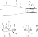
- said tip (20) comprises a proximal portion intended to cooperate with a fluid dispensing system and a distal portion (21), said proximal portion of generally tubular configuration and said distal portion (21) open tapered where the terminal base (25) of said distal portion (21) has an outer diameter of dimensions d3, and the upper base (24) of the said distal portion (21) has an outer diameter of dimensions d4, where said input region (8) comprises a vertical channel (18) which leads, optionally through one or more connectors, into said at least one microchannel (3), the upwards opening of said vertical channel (18) having a diameter of d2, where d3 ⁇ d2, said tip (20) and said vertical channel (18) being dimensioned so as to produce an interference coupling therebetween.
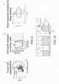
- Said interference coupling typically occurs according to one of the modes shown in figures 19 and 20 .
- said tip (20) and said channel (18) have as a sealed contact point the upper base (9) of said vertical channel (18).
- the sealed contact point is within the vertical channel (18), in this version being the terminal base (25) of the distal portion (21) of the tip (20) to come into contact with the inner wall of said vertical channel (18). In both cases, a sealed contact occurs.
- Said terminal portion (21) of said tip (20) and said vertical channel (18) are made of plastic and make the system resilient enough to ensure the seal, avoiding gaskets.
- the system geometries described hereinafter ensure that the contact between said vertical channel (18) and said tip (20) does not occur in a single point but is distributed on a surface portion, further ensuring an effective seal.
- this condition is advantageously verified where the semi-opening angle of said terminal portion (21) of said tip and said vertical channel (18) are little different, preferably differ by less than 10°.
- said vertical channel (18) is a cylinder, optionally slightly tapered downwards.
- the length of said distal portion (21) of said tip (20) is h2
- the semi-opening of the truncated cone formed by said distal portion (21) is (90°- ⁇ ) and the length of said proximal portion is h3.
- the reference is to figure 19 , in which said vertical channel (18) is a channel tapered downwards which has an upper base (9) and a lower base, said lower base having a diameter of dimensions d1 and said upper base (9) having a diameter of dimensions d2, said vertical channel (18) having a height h1 and the semi-opening of the truncated cone formed by said tapered channel trunk is (90° - ⁇ 1).
- ⁇ 1 is 90° and said vertical channel (18) is a cylinder.
- said measures ⁇ and ⁇ 1 differ from each other by up to 15°, preferably by 10°, even more preferably by a value of between 4 and 5°.
- said distal portion (21) of said tip (20) has a diameter section of dimensions d2 at a point (28) positioned along said distal portion (21) at a height h_x relative to the terminal base (25) of said distal portion, said height h_x being smaller than the distance between said upper base (9) of said vertical channel (18) and the input point in said microchannel (3), wherein said distance is h1 in the absence of any connector, where d3 ⁇ d2 ⁇ d4 and (90° - ⁇ 1) ⁇ (90° - ⁇ ), preferably ⁇ 1 is of between 80° and 90°, even more preferably is equal to 90°.
- said tip (20) fits into said input region (8) which is said vertical channel (18) by a portion (27) having length h_x, i.e. said tip fits into said input region (8) reaching the interference coupling point before reaching the microchannel (3), i.e. said tip and said vertical channel (18) comprised in said input region (8) reach the sealing position when the portion of said tip inserted in said vertical channel (18) is not such as to make said tip reach said microchannel (3).
- (90° - ⁇ 1) ⁇ (90° - ⁇ ) and h_x ((d2-d3)/2)*tg ⁇ , preferably ⁇ 1 is of between 80° and 90°, even more preferably is 90°.
- said tip (20) fits into said vertical channel (18) comprised in said input region (8) by a portion (27) having length h_x, where d1 ⁇ d3 ⁇ d2, (90° - ⁇ 1) > (90° - ⁇ ).
- said input region (8) comprises a connector (60), having an upper base which coincides with the lower base (12) of said vertical channel (18).
- said input region (8) further comprises a flare portion (30) hollow truncated conical in shape, having a height h4 and an upper base (33) and a lower base (9) which coincides with the upper base (9) of said vertical channel (18), said upper base (33) having a diameter d5 greater than diameter d2 of said lower base (9), where the half-opening of the truncated cone forming said flare portion (30) is (90° - ⁇ 2) where (90° - ⁇ 2) > (90° - ⁇ ).
- said input region (8) further comprises, above said flare portion (30), a storage region (40) which comprises at least two portions: an upper portion (42) and a lower portion (41), wherein said upper portion (42) has a generally tubular shape having an upper base (43) and a lower base (44) of diameter d6 and said lower portion (41) is tapered downwards and has an upper base (44) which coincides with said lower base (44) of said upper portion (42) and a lower base (45) of diameter d5, said storage region (40) has a height h5 and the half-opening of the truncated cone which forms said lower portion (41) is (90° - ⁇ 3), where ⁇ 3 is smaller than or equal to 90°, preferably ⁇ 3 is 0°.
- said tip (20) fits into said input region (8) by a length greater than the length of said distal portion (21) of said tip (20), the distance between said terminal base (25) of said distal portion (21) of said tip (20) and the upper base (43) of said storage region (40) is h_tot, (h_tot being > h2) and the distance between said upper base (24) of said distal portion (21) of said tip (20) and the lower base (45) of said storage region (40) is h_y, 2*h_y*cot ⁇ 3 + d5 being > d4.
- said input region (8) further comprises a storage portion (50) which comprises at least two portions: an upper portion (52) and a lower portion (51), wherein said upper portion (52) has a generally tubular shape having an upper base (53) and a lower base (54) of diameter d6 and said lower portion (51) is tapered downwards and has an upper base (54) which coincides with said lower base (54) of said upper portion (52) and a lower base (55) of diameter d2, said storage region (50) has a height h5 and the half-opening of the truncated cone which forms said storage portion (50) is (90° - ⁇ 3), where (90° - ⁇ 3) > (90° - ⁇ ).
- said tip (20) fits into said input region (8) by a length smaller than the total length of said tip (20), the distance between said terminal base (25) of said distal portion (21) of said tip (20) and the upper base (53) of said storage region (50) is h_tot, h_tot being smaller than or equal to h2 and (2*h_tot*cot ⁇ + d3) ⁇ d6.
- the embodiment which involves the presence of a storage tank in said input region (8) is advantageously used whenever the evaporation in the microfluidic device is to be controlled.
- said storage region can be advantageously left filled with the fluid charged in the microfluidic device so that, also when long incubation times are needed, there are no undesired evaporation effects.
- the optional presence of the storage region allows to have a vertical channel (18) and, optionally, connectors (60) whose volumes are reduced to a minimum, so as to avoid wastage of fluids, having one or more storage tanks for use only when needed.
- a flare portion (30) offers the advantage of providing an opening wide enough to allow a tip (20) fitting in said input region (8) also in a non-centered manner along the vertical central axis of the input channel (18) to enter into said flare portion (30) and then during the downward movement of said tip (20) in the input channel (18), by sliding the same tip along the inner walls of the flare portion and the input channel, even with a possible bending/curving of the tip (20).
- said microfluidic device (1) also comprises an impedance meter calibration plate and said tip (20) is connected to a dispensing system provided with an impedance detection system.
- said microfluidic device comprises a closing element of said input region (8), for example said closing element is a cap or a protective film.
- This protective film is, in one embodiment, of elastomer material, for example a silicone.
- the method of loading/unloading fluids in the microfluidic device (1) comprised in the kit described and claimed consists of the following steps:
- said vertical channel (18) and said optional connectors (60) also contain said liquid, or said liquid is not only contained in the microfluidic device.
- said presence of liquid in contact with the tip (20), by lowering the surface tension, facilitates the intake process which would be more difficult if said tip suctioned air before suctioning the fluid contained in said microfluidic device.
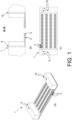
- a microfluidic device is also described, which is a reversed open microwell system which comprises an array of open microwells 2, at least one microchannel 3, at least one input port 8 for reagents and/or for one or more biological samples and at least one output port 10 for them, said input and output ports being in microfluidic communication with one or more of said microchannels 3, wherein said microchannel 3 has a cross-section area of micrometric dimensions and provides fluid to said microwells 2, wherein said reversed open microwell system is, in one embodiment, inserted in an automated management system which comprises the following features: an incubator at controlled temperature, humidity and CO 2 , fluid dispensing system, phase-contrast and fluorescence image acquisition.
- Said automated management system is achieved by assembling elements which are known in the art as a temperature, humidity and CO 2 control incubator, microplate pipetting systems, fluorescence and phase-contrast microscopy lenses connected to an image acquisition camera, such as a CMOS or CCD camera, where said elements are managed in whole or in part by software known to those skilled in the art through hardware connected thereto.
- elements which are known in the art as a temperature, humidity and CO 2 control incubator, microplate pipetting systems, fluorescence and phase-contrast microscopy lenses connected to an image acquisition camera, such as a CMOS or CCD camera, where said elements are managed in whole or in part by software known to those skilled in the art through hardware connected thereto.
- each microchannel 3 is associated with an input port 8 and an output port 10.
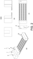
- the microfluidic device (1) also comprises reservoirs 6, 7, where said reservoirs are at least one reservoir 6 for reagents and at least one reservoir 7 for one or more biological samples.
- Said reservoirs are selected from the group comprising: plates, one or more multiwell plates, such as 96-well plate, eppendorf tubes.
- Said reservoirs 6 and 7 may be 2, or 4, 8, 16, 24, 48, 96, 384.
- said reservoirs 6, 7 are integrated in said open reversed microwell system 1.
- said at least one input port 8 for reagents also comprises a storage area 11.
- said reagents and/or said biological sample are parked in said storage area before crossing said input port 8.
- said output port 10 may optionally comprise a storage area 11.
- Said storage area is preferably located above said input port and in a preferred embodiment, advantageously consists of two portions: an upper portion 13 and a lower portion 14.
- Said upper portion 13 has a cylindrical shape and said lower portion 14 has a funnel shape, where said upper portion 13 is a cylinder with a base having a diameter greater than the diameter of said input port 8 and said lower portion 14 is a funnel which connects said upper portion with said input port.
- said discharge region (70) intended to discharge the fluids from said microfluidic device (1) which comprises at least one input region (8) comprises a discharge container in fluidic connection with said microfluidic device (1) through at least one discharge channel and an output port (10).
- said fluid pushed by a pressure applied in said input region (8) in said microfluidic device (1), unidirectionally reaches said discharge container where volume V of said fluid is smaller than or equal to the volume of said discharge container.
- said discharge channel emerges from the at least one microchannel (3) comprised in said microfluidic device (1) and is a siphon.
- the diameter of said discharge channel is such that the siphon exerts a capillary force on the fluid contained in said microchannel (3).
- said discharge channel is located on the bottom of at least one microchannel (3) and is almost orthogonal thereto and puts said at least one microchannel (3) in communication with said discharge container which is placed below the same microchannel (3).
- said output port (10) is placed on the bottom of said at least one microchannel (3) and leads into a first discharge container (12a), positioned below said microchannel (3) and said discharge channel (22) leading to said discharge container protrudes from said first discharge container (12a).
- the discharge channel is a siphon.
- Said discharge channel preferably has a cross-sectional area of micrometric dimensions, said dimensions being between 100 ⁇ m and 5 mm, preferably between 500 ⁇ m and 2 mm.
- the kit according to the present invention comprises a microfluidic device as described above.
- the kit according to the present invention comprises the microfluidic device as described above, also characterized by the fluid discharge region described above.
- the microfluidic device (1) comprises an input region (8) adapted to be included in the kit according to one of claims 1 to 8 and a discharge region (70) according to claim 10.
- the present invention relates to a method for charging/discharging fluids from a microfluidic device, where said method comprises:
- said method further comprises:
- the microfluidic device (1) is an open reversed microwell microfluidic device (2) and further comprises reservoirs (6) for reagents and reservoirs (7) for one or more biological samples.
- said device comprises 16 microchannels (3), each having an input region (8) and an output region (10), wherein each of said microchannels (3) faces towards 1200 open reversed microwells.
- microfluidic device (1) which comprises the input region (8) according to the present invention is particularly advantageous, since it:
- a further aspect of the present invention is a method for managing a microfluidic device (1) with open reversed microwells (2) comprising at least one input region (8), at least one output region (10) and at least one microchannel (3), wherein said method comprises:
- said method is implemented in a microfluidic device (1) comprising an input region (8) according to one of claims 1 to 8 and a discharge region (70) according to claim 10 and is characterized in that if the overall volume of said first and optionally, second and further fluid introduced in said microfluidic device (1) is smaller than the volume of said discharge container (12), said fluids do not mix with one another.
- the method described hereinafter surprisingly allows not only an analysis in time-lapse but also processing during said time-lapse analysis. That is, with the method of the present invention it is possible not only to monitor the same sample at different times (typical time-lapse analysis), but also handle the same sample at different times, the surrounding conditions varying over time and in a controlled and automated manner.
- the methodology described herein allows to evaluate, for each individual cell, the variation of morphological and functional parameters following a controlled exposure to a pharmacological agent, where said agent is added during such monitoring.
- a dynamic analysis of the sample is possible, where dynamic analysis means herein a sample analysis performed at different times after the exposure to treatments of interest.
- the dynamic analysis carried out according to the present invention it is possible to identify a cell sample insensitive to a treatment so as to expose it to a different treatment.
- the method claimed herein allows the implementation of a large scale high-content assay with processing in time-lapse, operator-independent, having equipment which can be installed in any analysis laboratory.
- Said open reversed microwell system 1 comprises a series of microsells 2, open at both ends, arranged as a matrix.
- Said open reversed microwell system 1 further comprises at least one microchannel 3, wherein said at least one microchannel 3 has a cross-sectional area of micrometric size and provides fluid to said microwells 2.
- Said system further comprises at least one input port 8 for reagents and/or one or more biological samples and at least one output port 10 thereof, said input and output ports being in microfluidic communication with one or more of said microchannels 3.
- each microchannel 3 is associated with an input port 8 and an output port 10.
- said reagents are contained in reservoirs 6, 7, where said reservoirs are at least one reservoir 6 for reagents and at least one reservoir 7 for one or more biological samples.
- Said reservoirs are selected from the group comprising: plates, one or more multiwell plates, such as 96-well plate, eppendorf tubes.
- Said reservoirs 6 and 7 may be 2, or 4, 8, 16, 24, 48, 96, 384.
- said reservoirs 6, 7 are external to said open reversed microwell system 1. In a preferred embodiment, outlined in figure 3 , said reservoirs 6, 7 are integrated in said open reversed microwell system 1.
- said at least one input port 8 for reagents also comprises a storage area 11.
- said reagents and/or said biological sample are parked in said storage area before crossing said input port 8.
- said output port 10 may optionally comprise a storage area 11.
- Said storage area is preferably located above said input port and in a preferred embodiment, advantageously consists of two portions: an upper portion 13 and a lower portion 14.
- Said upper portion 13 has a cylindrical shape and said lower portion 14 has a funnel shape, where said upper portion 13 is a cylinder with a base having a diameter greater than the diameter of said input port 8 and said lower portion 14 is a funnel which connects said upper portion with said input port.
- the present invention also relates to a method for the large-scale, high-content analysis of biological samples, wherein said biological samples are as defined as above, which comprises the following steps, not necessarily in this order:
- said open reversed microwell system is the microfluidic device according to claim 9; in a further embodiment, it is the microfluidic device according to claim 11, or is a microfluidic device 19 which also comprises the kit according to one of claims 1 to 8.
- said reservoirs 6, 7 are external to said open reversed microwell system 1, as outlined in figure 2 , and said charging of reagents and of the at least one biological sample is done manually, i.e. by means of automated fluid dispensing systems, taking from the reservoirs and charging into the input ports 8.
- said reservoirs 6, 7 are inserted in the automated system with the open reversed microwell system.
- said reservoirs 6, 7 are integrated into said open reversed microwell system 1 and said charging of reagents and of the at least one biological sample is done manually, i.e. by means of automated fluid dispensing systems, taking from the reservoirs and charging into the input ports 8.
- said reservoirs 6, 7, integrated in said open reversed microwell system 1 are in fluidic communication with said at least one input port 8.
- said reservoirs 6, 7 are arranged as described above, i.e. are external or integrated into the open reversed microwell system.
- some of said reservoirs 6 are precharged with said reagents prior to carrying out the method, even days or months before carrying out the latter, so as to have specific ready-to-use reservoirs 6.
- the only manual step required by the operator is precharging the biological sample in said one or more reservoirs 7.
- a further manual step performed by the operator is charging one or more drugs in one or more of said reservoirs 6.
- said reservoirs 6, 7, integrated or external to said open reversed microwell system, preloaded with the reagents and the biological sample, are introduced into said automated system.
- said charging steps d) and e) through said input ports, also referred to as input regions (8) take place following said step c) of introducing in the automated system said open reserved microwell system in which said reservoirs 6, 7 are integrated, or said open reversed microwell system and said reservoirs 6, 7 external thereto, preferably by automated pick up of the biological sample from said reservoirs (7) and consequent arrangement of the cells contained therein in one or more of said microwells (2) and optionally, subsequent introduction of drugs in one or more of said microwells and/or dyes, and/or one or more labeled antibodies, and/or one or more cell viability markers, wherein said dyes, and/or one or more labeled antibodies and7or cell viability markers are fed to said input ports (8) from said reservoirs (6).
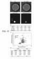
- Said morphological/functional classification derives from the fluorescence analysis with resolution of a single cell, a single cell aggregate or the entire cell population which is contained in a single microwell.
- Said parameters are acquired and analyzed automatically, through the use of systems known to those skilled in the art.
- morphological parameters measures relating to the size and shape of the cell.
- functional parameters those features observed due to the markers, such as the expression of specific antigens.
- said method also comprises, after introducing said open reversed microwell system into said automated system:
- said method further comprises:
- said method allows, for example, the ex-vivo analysis of the drug activity, where the classification of said cells present in said biological sample carried out in said step p) allows a direct comparison between, for example, the responsiveness to treatment of healthy cells and cancer cells present in the same biological sample, or a comparison of the response of the same cell type to different treatments.
- said method further comprises, after said step l):
- said method further comprises, after said classification step p):
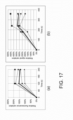
- said drugs are dispensed in at least two different concentrations and said cellular viability analysis, when present, leads to obtaining a specific cell dose/response curve for the one or more drugs tested.
- the dilutions of each drug are prepared by the liquid dispensing system by mixing the drug with a diluent.
- the method involves, after said image acquisition of step j), the count of the average number of cells in each microwell 2 and the subsequent dilution of the sample, through said fluid dispensing system, so as to achieve a target concentration, i.e. a concentration which ensures the desired number of cells per each microwell, and the subsequent charging of the sample thus diluted into one or more microchannels of said open reversed microwell system, which microchannels are different from the one or more channels used in step d) above.
- a target concentration i.e. a concentration which ensures the desired number of cells per each microwell
- step k) if the combined administration of at least two drugs is required, said two or more drugs are optionally combined by a liquid dispensing system by mixing, prior to charging, the content of at least two reservoirs 6 containing said drugs.
- Said method is characterized in that it uses a biological sample whose volume ranges from 1 ⁇ l to 1 ml, preferably from 10 ⁇ l to 100 ⁇ l, with a cell concentration of between 5,000 cells per ml and 5,000,000 cells per ml.
- said filling buffer comprises RPMI medium supplemented with bovine fetal serum (FBS) 10%, and preferably a cell death marker, typically propidium iodide (PI) 5 ⁇ M.
- FBS bovine fetal serum
- PI propidium iodide
- Said open reversed microwell system 1 of which figure 1 shows a perspective (a), vertical section (b) and top (c) view and figure 5 shows a perspective sectional view, in a preferred embodiment comprises 1200 microwells 2 per each microchannel 3 and 16 microchannels 3; in a further embodiment, it comprises 500 microwells 2 and 5 microchannels 3.
- said method analyzes a biological sample which contains only about 10-20 cells and uses the open reversed microwell system of the type described in WO2012/072822 .
- said biological sample is obtained from an animal and/or a human suffering from cancer and said biological sample comprises healthy cells and cancer cells.
- DAPI a dye which can be used in the method
- Others dyes which can be used in the method can be selected from the group comprising: Calcein-AM, carbocianine such as DiD, DiO, DAPI (4', 6-diamidino-2-phenylindole).
- Other dyes which can be used for the purposes of the present method are cell death markers, such as PI, Calcein-AM, JC1, Caspase 3/7, Annexin V.
- labeled antibody are used as dyes.
- said method comprises a reiteration of the treatment, where the cells which survive a first exposure to one or more of said drugs listed in step k), are exposed again to a further drug treatment, where said further treatment involves the exposure to one or more of said drugs already used in said step k) at higher concentration, or where, in said further step, one or more drugs other than those used in the previous step are used.
- the reiteration of the method takes place, in one embodiment, on the cells which remain alive in said one or more microwells 2, where said further extra treatment is made possible since, in said open reversed microwell system, said microchannel 3 is emptied of said fluid comprising one or more drugs and subsequently filled with a second fluid comprising said further one or more drugs.
- the cells by remaining positioned on the meniscus at the air/fluid interface, are not affected by the fluid change in said microchannel. Said cells located on the meniscus, even if they are not cells growing in adhesion, from a fluidic point of view behave like cells growing in adhesion on the bottom of a closed well, where it is typically possible to replace the culture medium without affecting said cells in adhesion.
- the advantage of the present embodiment is to be found in its use also with cells which grow in suspension, where said meniscus allows to mimic the bottom of a well without imposing a forced adhesion on said cells, such as using substrates which stimulate cell adhesion known to those skilled in the art. This is particularly advantageous as it allows the least impact on the biological sample, preventing imposing of external conditions alien to the physiological context.
- said method comprises the following steps, in this order:
- Cancer cells are identified by dimensional and shape parameters, such as membrane roughness, and by the bonding with labeled antibody specific for tumor antigens, where the presence or absence of a specific signal emitted by one or more specific labeled antibodies determines the identification of the cell type.
- an anti-CD38 antibody is used for the differential analysis of tumor cells; if the tumor under investigation is acute myeloid leukemia (AML), an anti-CD34, or anti-CD117, or anti-HLA-DR, or anti-CD33/CD14 antibody is used.
- the drugs tested are selected from monoclonal antibodies, for example Alemtuzumab, Bevacizumab, Cetuximab, Ibritumomab, Ofatumumab, Panitumumab, Rituximab, Tositumomab, Trastuzumab, chemotherapy drugs, such as cytarabine, idarubicin, fludarabine, decitabine, 5-azacitidine and small molecules, such as ibrutinib, idasanutlin, venetoclax, wherein the method of the present invention measures the complement-mediated cytolytic activity, in the case of monoclonal antibodies, or the direct cytotoxic activity, in the case of chemotherapy drugs and small molecules.
- monoclonal antibodies for example Alemtuzumab, Bevacizumab, Cetuximab, Ibritumomab, Ofatumumab, Panitumumab, Rituximab, Tositumomab
- the automated analysis of images obtained using the method of the present invention allows to extract the information related to each individual cell or cluster of cells, captured in the acquired images.
- the cells contained in the microwells may be collected and used for subsequent analysis.
- the method described herein allows to select one or more wells in which cells of particular interest are contained, such as drug-resistant cells injected into a specific microchannel, recharging said cells into reservoir (7) of a further open reversed microwell system, dispensing them to a greater dilution to obtain microwells containing a single cell.
- the desired cell Once the desired cell has been identified, it can be isolated. Assays are conducted on said one or more isolated cells as known to those skilled in the art, such as RT-PCR.
- the biological sample can be charged or collected/explanted, or it can be processed in advance so as to make it available in the method according to the present invention.
- said processing preferably involves a red blood cell separation step with techniques known to those skilled in the art, preferably on a density gradient, or through the use of a lysis buffer.
- said sample comprises suspension cells
- said cells are counted and diluted to the dispensing concentration.
- said count and dilution step is done automatically by the system.
- said processing typically comprises isolating a fragment sized between 10 ⁇ m and 1000 pm, a size compatible with the microfluidics used.
- said biological sample is used as is as an isolate from animal and/or human.
- Figure 6 shows an example of a series of images taken at time T1 in a biological sample consisting of leukemic cells from a cell line mixed with blood obtained from a healthy donor.
- the biological sample therefore contains healthy PBMC and cancer cells.
- the image is obtained in the visible (A), in the DAPI fluorescent channel with a dye (B), in the FITC fluorescent channel for the labeled anti-CD45 antibody signal (C) and in the fluorescent channel CY5 for the labeled anti-CD34 antibody (D).
- (E) shows the overlap of said images (C) and (D).
- the method has been demonstrated to have a high sensitivity and a high specificity when applied to cell classification, as evidenced by image (E) in which all the cells present in the sample are found, namely those of the image in (B), where all cells are CD45 positive (C) only and only a part thereof is also Cd34 positive (D).
- image (E) in which all the cells present in the sample are found, namely those of the image in (B), where all cells are CD45 positive (C) only and only a part thereof is also Cd34 positive (D).
- FIG 8 shows the graphs of the acquired data analysis, in relation to the classification of cancer cells.
- C shows the distribution of the cells stained with dye CMAC and not stained with anti-CD34/CD45 antibodies. This distribution allows to determine the maximum signal identified in such negative control, and as a result to set a minimum threshold for the classification.
- D the count made after anti-CD34/CD45 labeling was carried out keeping the threshold identified at (C) and classifying the cells characterized by a signal emitted by the antibody higher than the threshold as cancer cells.
- the cancer cells can be classified as such as they are positive to the anti-CD34 antibody (CD34+) and as they are positive to both anti-CD34 and anti-CD45 antibodies (CD34+/CD45+).
- panels (A) and (B) show the results obtained by flow cytometry on the same samples. These results show that the data obtained with the method of the present invention are absolutely comparable with those obtained for the same sample by flow cytometry, which is the technique of choice for this type of analysis and cell counting.
- said cells are stained with cell viability markers.
- cell viability markers propidium iodide (PI) or Annexin V are commonly used markers in this regard: if the membrane is damaged, PI enters the cells and emits fluorescence after binding to nucleic acids. The labeled cells are therefore those with compromised or destroyed membrane and should be considered as dead.
- Another commonly used cell viability marker is calcein-acetoxymethyl (calcein-AM) ( Lichtenfels R et al., CARE-LASS calcein-release-assay, an improved fluorescence-based test system to measure cytotoxic T lymphocyte activity. J Immunol. Methods 1994, 172:227-239 ). Calcein acetoxymethyl ester crosses the cell membrane passively and, once inside, it is converted by an intracellular esterase into calcein, which is a polar fluorescent product retained into the viable cells but released by cells whose membrane is damaged and therefore considered death.
- Figure 9A-9B shows an example of an analysis carried out on a biological sample which includes lymphoma cell line Raji cells, and white blood cells.
- a treatment with a drug, specifically Rituximab was performed according to the method of the present invention.
- Panel (A) shows the ability of the method according to the presence t of invention to differentiate between cancer cells (circle) and healthy cells (square), using morphological parameters and the CD38 marker simultaneously.
- (B) shows the cell viability data, obtained by quantifying the presence of calcein-AM in the cell, in particular by comparing the signal emitted after treatment with the drug with the signal emitted initially, where the signal reduction is associated with the loss of viability.
- the reference threshold is determined using a control consisting of a channel in which the sample is not exposed to the drug.
- known references in the literature concerning the physiological loss of signal are used ( Neri S et al., Calcein-Acetyoxymethyl Cytotoxicity Assay: Standardization of a Method Allowing Additional Analyses on Recovered Effector Cells and Supernatants. Clin. Diagn. Lab. Immunol. 2001, 8:1131-1135 ).
- Figure 9C shows the dose/response curves obtained for a different model consisting of leukemic cell lines (KG-1, Kasumi-1 and HL-60) for which a response analysis to the chemotherapy drug idarubicin was carried out.
- a biological sample resulting from the explantation of a liver cancer can be used in the present method, after partial non-enzymatic breakdown.
- the biological sample is then labeled and charged in said reservoirs.
- an open reversed microwell system is available which is ready for analysis, comprising cell clusters and isolated cells.
- the possibility of assessing the effect of drugs also on cell clusters is very advantageous, as it also allows to assess any changes in volume of the same cluster, in addition to different labeling areas in the same cluster. It is also possible to acquire images on different focal planes, in this way being able to also reconstruct a 3D image of the cluster.
- Figure 10 shows the diagram of an open reserved microwell system which also comprises electrodes 5 arranged around said microwells 2 and on the base of said microchannel 3. Said electrodes 5 have the function of conveying cells 4 present into microchannel 3 into microwell 2 in the desired time and mode. The electrodes thus promote the formation of cell clusters within the microwells, thus allowing therefore an analysis which also takes into account the specific cell: cell interactions.
- the method described herein facilitates a personalized medicine approach, which is strongly needed especially when intervening in tumor diseases.
- the method described herein surprisingly allows testing on a biological sample ex-vivo, even comprising a few cells only, such as only about 10-20 cells, if the open reversed microwell system used in said method is of the type described in WO2012/072822 , the effect of different drugs so as to allow the choice of the most effective drug for the specific patient and/or the optimal dose for the specific patient and/or the determination of the resistance of the patient sample to one or more drug therapies.
- the analysis is performed immediately after collection of the biological sample and is completed over a period of about 24 hours.
- said method is applied without having a substantial impact on the operational procedure, as it does not require dedicated withdrawals.
- a volume smaller than 1 mL is typically sufficient.
- volumes equal to 1 mL are typically sufficient to run multiple tests, i.e. 0.1 mL or less to run a single test.
- a sample from needle aspiration can offer enough material.
- the method developed herein allows the use of complex samples, including cellular and serum samples, with enormous advantages from the point of view of conditions as close as possible to the physiological ones, to improve the predictive value of the assay.
- the method described herein allows a high-content analysis, with resolution up to a single cell, performing both a dynamic analysis (time-lapse) and a dynamic processing of the sample (using a programmable change of the fluids surrounding the sample over time), which are highly wished features as they allow to monitor and compare the evolution over time of a given cell with specific features, automate the sample preparation and the administration of drugs, and implement complex protocols involving, for example, the inclusion of sequences of drugs or the labeling with specific reagents, such as Annexin V, at the end of the incubation period with the drug for determining the outcome of the experiment in terms of viability, induction of apoptosis or assessment of the activation of specific pathways associated with the activity of the drug.
- specific reagents such as Annexin V
- the process is fully automated, the operator's intervention is minimum, i.e. only when charging the biological samples and reagents and drugs into the reservoirs.
- the intervention is exclusively limited to the charging of the biological sample, when the open reversed microwell system comprises reservoirs already charged with reagents and drugs, minimizing thus errors, reducing the risk of cross-contamination and significantly increasing the reproducibility of the results.
- PBMC peripheral blood mononuclear cells
- Isolated PBMC were washed twice with 10 mL cold HBSS after lysis of red blood cells. The concentration of cells and their viability was determined with Trypan Blue on haemocytometer. The concentration was adjusted to 1 million cells/mL.
- SU-DHL-4 or Raji cells were harvested at the peak of their growth, washed with PBS and counted in a hemocytometer with Trypan Blue. The cell concentration was adjusted to 1 million cells/mL and they were labeled with Calcein AM (CAM) 5 nM for flow cytometry and 250 nM for the assay according to the present invention. The labeled cells were washed once in PBS and resuspended in RPMI. The same protocol was used to label with freshly isolated CAM PBMC. Cell viability was finally assessed by PI and flow cytometry.
- Calcein AM CAM
- 10 ⁇ 5 CAM labeled cells for each batch were seeded in duplicate on a 96 well plate.
- the control group (CTRL) was treated with RPMI supplemented with PI to a final concentration of 1.5 ⁇ M.
- the treatment group was treated with Rituximab (RTX) to a final concentration of 10 pg/mL in RPMI supplemented with PI to a final concentration of 1.5 ⁇ M and incubated at room temperature for 5 min. Soon after, human serum (hS) was added to a final concentration of 1%.
- the final volume of each well was 200 pL. 50 ⁇ L samples were harvested at time 0, 30 and 60 min. after adding hS, and analyzed at the FACS (FACSAria BD, USA).
- CAM labeled cells were resuspended in RPMI to a final concentration of 2 ⁇ 10 ⁇ 6/mL.
- the RTX group was treated with Rituximab to a final concentration of 10 ug/mL off-chip and incubated at room temperature for 5 min.
- CTRL and RTX cells were seeded in the open reversed microwell system as described, obtaining an optimum number equal to or smaller than 7 cells per well.
- the channels were rinsed with PBS on 20% FBS.
- a first set of images was acquired to set the initial conditions (Tbaseline).
- the CTRL channel was treated with RPMI integrated with hS to a final concentration of 1% and PI at a concentration of 5 ⁇ M.
- the RTX channel was treated with RPMI supplemented with Rituximab 10 pg/mL, HS 1% and PI 5 ⁇ M.
- Time-lapse images T1, T2, T3, T4 were acquired every 15' and up to one hour after treatment.
- the images were acquired in brightfield (BF) to evaluate the morphological characteristics and then in fluorescence to evaluate the signal in DAPI bands (ex: 360/40 nm, em: 460/50 nm), FITC (ex: 480/30 nm, em: 535 / 40nm), TRITC (ex: 540/25 nm, em: 605/55 nm). All images were acquired with 10x lens with a Nikon camera. During the imaging, the microscope worked in a controlled atmosphere at 37 °C, 95% humidity, 5% CO 2 .
- SU-DHL-4 cancer cells were labeled with CAM and then charged into the open microwell system, treated with drug in the case of the RTX group and observed.
- Panel A shows a sequence of time-lapse images of CTRL and RTX treated samples at times T0 5-10 min, T1 30 min and T3 60 min.
- the cells indicated by the arrows refer to the color acquired in the TRITC channel (PI) and represent dead cells. They are present only at T2 and T3 in the RTX group. With greater contrast, the cells acquired in the FITC channel are seen, i.e. live cells labeled with Calcein-AM.
- Panel B shows the data obtained with the FACS.
- Panel C shows the histograms of FACS analysis and according to the method of the present invention at time T2 60 minutes. The percentages refer to the population of Calcein-AM positive cells, i.e. living cells.
- the method according to the present invention further proves to be able to provide important results, not obtainable with flow cytometry.
- Raji cancer cells and PMBC it was possible, thanks to the CD38 labeling, to stain and selectively observe cancer cells.
- Raji cancer cells and PBMC were labeled with CAM and with an anti-CD38 antibody Alexa Fluor 488 1:10, separately. A portion of the cells was then mixed in a 1:1 ratio.
- Raji cells, PMBC and the mixture were then plated in three different channels of the open reversed microwell system and then observed.
- cancer cells highlighted in A for the selective staining with the anti-CD38 antibody with respect to the total cells stained with CAM, are easily highlighted by the method of the present invention not only for the fluorescence associated with the specific marker (panel C) but also for the morphological parameters (panel B and D)
- the acquisition of images in time-lapse has the advantage of providing an accurate analysis of every cellular response to stimuli represented, for example, by drug treatment, where the precise analysis is obtained by evaluating the relative variation of fluorescence which, in case of staining with a vital dye, provides a means to determine the cellular response. Even where the initial staining is not uniform, the signal from each cell is then normalized to its initial value. In comparison, the absolute fluorescence analysis after the application of a treatment, as typically provided by flow cytometry, provides a less accurate result in this case.
- Figure 14 compares the distribution obtained by dynamic analysis, i.e. variation of relative fluorescence in A, versus the distribution of the data obtained in absolute terms, in B.
- the first distribution in Figure 14A was obtained according to the method described herein on Raji cells after exposure to Rituximab.
- the cells showing a reduced signal intensity variation represent a subpopulation of possibly resistant cells, or which underwent minor damage.
- cells for which the variation was less than a 45% decrease were selected, indicated with a star (*) in the figure, and they were analyzed within an analysis showing the variation in absolute terms ( Figure 14B ).
- the columns marked with a star indicate the presence of at least one cell identified as resistant from the previous analysis.
- the uninterrupted line marked by the rhombus indicates the result over time with the method according to the present invention, where a decrease of 79.1% of the background noise is observable after 5 minutes of continuous infusion of the washing solution at a rate of 16 pL/minute.
- the dashed line represents the result obtained through the standard centrifugation process, where the result obtained after 4 washing cycles separated by 5 minutes centrifuge at 1000 RCF is shown.
- the uninterrupted line marked by the triangle shows the result obtained after 2 cycles separated by 5 minutes centrifuge at 1000 rcf.
- the method according to the present invention allows to obtain comparable results, with the obvious advantage of not requiring lengthy centrifugation which inevitably leads to loss of biological material, which loss in some situations may be significant to a point susceptible to compromise the analysis itself, as well as an exposure of the biological sample to additional stress.
- Cells from the Jurkat cell line (human Leukemic T cells) were obtained from ATCC and cultured in RPMI 1640 medium supplemented with 10% inactivated FBS medium, 10 mM Hepes, 2 mM Ultraglutamine and 1 mM sodium pyruvate, 1% Penicillin/Streptomycin in 25 cm 2 flasks at 37 °C and 5% CO 2 .
- the OKT3 hybridomas were cultured in bioreactors (CellLine, Integra Biosciences) in complete RPMI 1640 medium containing 3% FBS and the supernatant was collected 2 times a week.
- the purification of monoclonal antibodies was performed using a double saturated ammonium sulfate precipitation at 30% and 50%, followed by dialysis in PBS.
- the purity of OKT3 was assessed by SDS-PAGE gel and the amount of antibody was determined through NanoDrop (Thermo Scientific). The antibody was then frozen at -80 °C before use.
- the measure of calcium signal on entire populations of Jurkat cells was performed following the protocol Fluo-4 (Life Technologies). 1 ⁇ 10 6 Jurkat cells were washed once in HBSS and incubated with Fluo-4 (4 ng/pL) for 30 minutes at 37 °C. After washing and resuspension in HBSS, the cells are treated with the purified antibody OKT3 at the concentrations of 1, 5 and 10 ug/mL or, alternatively, using 50 ⁇ L of supernatant from hybridoma culture. As a positive control of the calcium flow, Ionomycin (Sigma-Aldrich) 2 pg/mL was added. The cells thus treated were then analyzed at the flow cytometer.
- Jurkat cells were labeled with Fluo-4 20 ⁇ M in HBSS, centrifuged and resuspended in serum-free medium (RPMI 1640 with 25 mM Hepes or HBSS) at a concentration of 1.6 ⁇ 10 6 cells/mL in 1.5 mL Eppendorf tubes used as input reservoirs for the open reversed microwell system.
- serum-free medium RPMI 1640 with 25 mM Hepes or HBSS
- the solutions containing Ionomycin (2 pg/mL) or OKT3 (10 pg/mL) are made to flow into specific microchannels of the open microwell system via peristaltic pump.
- the images were acquired by a camera connected to the microscope at a distance of 1 minute and processed by software developed in LabView, quantifying the dynamic performance of the same signal on each sample cell.
- Cytofluorimetric results the progress of the average sample fluorescence following the injection of Ionomycin (a) or OKT3 (b) in the sample was quantified at flow cytometer, obtaining the results shown in Figure 16 .
- the charts show the average variation of the fluorescence intensity and confirm the functioning of the model used.
- Ionomycin stimulation in open microwells the stimulation with Ionomycin showed an average increase of the signal, with respect to the baseline, equal to 193% +/-139% in a series of 10 experiments.
- the typical pattern observed is that shown in Figure 17 (a) .
- the signal settles on stably high values.
- the stimulation with OKT3 showed an increase of the signal peak, compared to the baseline value, equal on an average to 178% +/-90% in a series of 3 experiments.
- the typical pattern observed is that shown in figure 17(b) .
- the signal reached the peak value in a few minutes.
- the comparative experiment shows that the method according to the present invention allows to have data comparable to those obtained with the method of choice, i.e. flow cytometry.
Description
- With the progress of knowledge related to genomics, the need to move from a treatment generally applicable to a given disease to a treatment specifically applicable to a specific individual affected by the such a disease is increasingly felt in medicine. The advantages of a customized therapeutic approach are apparent, where an inadequate selection of patients to be treated leads to a health expenditure which may be contained not only by being able to predict, and thus avoid, often expensive and ineffective treatments for the specific subject but also avoiding adverse patient-specific effects.
- In tumor therapy, this need is particularly felt, where the effectiveness of treatments is typically low: even drugs aimed at specific genetic mutations may be ineffective in 80-90% of cases in the absence of an adequate selection of patients (B Majumder et al., Predicting clinical response to anticancer drugs using an ex vivo platform which captures tumour heterogeneity. Nat. Commun. 2015, 6:6169).
- With the aim of being able to achieve tests which enable the effective implementation of customized medicine, tests have been successfully developed which are based on the genetic profile and on protein expression (Staunton JE et al., Chemosensitivity predicition by transcriptional profiling. PNAS 2001, 98:10787-10792; van't Veerand LJ, Bernarnds R, Enabling personalised cancer medicine through analysis of gene-expression patterns. Nature 2008, 452:564-570). However, especially in tumors, the relevance of the tumor microenvironment in conjunction with other characteristics of the patient to determine the effectiveness of a therapy has been widely demonstrated. To take also these factors into due consideration, the need for ex vivo functional assays is strongly felt (Tian C. et al., Evaluation of a chemoresponse assay as a predictive marker for the treatment of recurrent ovarian cancer: further analysis of a prospective study. British J. Cancer 2014, 111:843-850) .
- Ex-vivo functional assays are currently available which, where implemented by carrying out the analysis immediately downstream of the biological sample collection and maintaining said sample under controlled conditions and as much as possible similar to those representative of the tumor microenvironment in-vivo, have demonstrated a high ability to predict the efficacy of drug therapies. As an example, a method is described in
WO2010/135468 . However, the ex-vivo functional assays available to date exhibit important limitations. - In particular, the assays developed for the ex-vivo analysis of the pharmacological activity in hematology and oncology are mainly based on the use of flow cytometry (FACS) and/or fluorimetric or colorimetric assays involving kits used to measure the cell viability and/or proliferation on whole cell populations, such as the metabolic assays MTT, ATP, the MiCK assay (Kravtsov VD & Fabian's Automated monitoring of apoptosis in cell suspension cultures. Lab. Invest. 1996, 74:557-570) and the DiSC assay (Weisenthal LM et al., A novel dye exclusion method for testing in vitro chemosensitivity of human tumors. Cancer Res. 1983, 43:749-757) for measuring ell death and apoptosis. Such assays inevitably have several limitations. Flow cytometry, for example, exhibits the inability to obtain high-content analyses in time-lapse and the inability to work on cell aggregates, as the cellular breakdown is a fundamental prerequisite for running the test, thereby preventing the evaluation of the response of a cell in its context. The techniques which provide a measure on whole populations are generally characterized by the difficulty of carrying out an analysis limited to the tumor subpopulation and are therefore of limited accuracy. In addition, in all the techniques described, the required sample volumes are typically significant and not always compatible with the clinical practice. For example, in order to reduce the invasiveness of the sampling procedures or in the presence of tumors of limited size, such as metastasis, the sample is available in small quantities, for example up to a few thousands cells or a few dozen cells, if the sample comes from a liquid biopsy, i.e. by the isolation of circulating tumor cells, insufficient quantities to be analyzed according to the techniques described. Having a biological sample which comprises between a few thousands cells and a few dozen cells, conducting a cell analysis on such a sample is difficult to implement through the currently existing instruments and, when it can be implemented, the analysis is still limited to one or very few experimental conditions per sample. In even more complex cases in which only a few cells, such as 10-20 cells, are available, no significant data can be obtained using the functional assays currently available. Moreover, functional assays are currently typically carried out by operators who require specialized laboratories, with expertise and equipment which are not easily accessible. The analysis platforms based on flow cytometry, if provided with complete automation, are represented by complex and bulky machinery, therefore hardly adoptable in clinical contexts and, more particularly, in diagnostic laboratories. Likewise, other techniques described require manual performance of the operations and the availability for an entire laboratory to carry out the diagnostic testing. The tests are then carried out in laboratories far from the place of sampling, thereby delaying the start of the test by a few days, often making them not compatible with the timing of clinical practice, which may need the results within 24-48 hours.
-
WO2012/072822 describes a system with microwells open upwards and downwards, where channels put said microwells in fluidic communication and the geometry of said microwells allows the formation of a meniscus within them on which the cells and/or particles introduced into the same rest. In particular, it discloses: - A tip;
- A microfluidic device which is a reversed open microwell system which includes an array of open microwells, at least one microchannel, at least one input port for reagents and/or for one or more biological samples and at least one output port for them, said input and output ports being in microfluidic communication with one or more of said microchannels, wherein said microchannel has a cross-section area of micrometric dimensions and provides fluid to said microwells; and that said input region comprises a vertical channel leading into said at least one microchannel, the upward opening of said vertical channel having a diameter of d2 and a height h. Optionally, said microwells comprise electrodes which allow to control the movements of cells and/or particles into the same microwells.
-
US2016/161392 describes a microfluidic device wherein reservoir are in contact with a microscale channel.US2013/309146 describes means to transfer fluid from a tip to a trap column with minimal loss. Patricio Godoy et al. 2013 Archives of Toxicology 87(8):1315-1530 describes in vitro system to investigate hepatotoxicity. - The need is strongly felt for a functional assay based on cell analysis capable of giving answers in a short time since obtaining the biological sample, for example within 24-48 hours, and which allows to obtain high-content data on the cells analyzed, i.e. inclusive of morphological information, even in time-lapse, allowing the dynamic analysis of the information detected on the cells in the sample. Moreover, said assay should be as operator-independent as possible and require small volumes of biological sample, so as to also limit the volumes of reagents and drugs to be used in the execution thereof, thus containing costs, maintaining the ability to provide reliable results even with very small biological samples in terms of quantity, such as also having just 20 cells.
- The movement of fluids in microfluidic devices typically uses vacuum or pressure pumps and/or valves. The combination of pumps and valves allows a fine control of the movements of fluids in a circuit.
- By way of example, Byun et al. (Pumps for Microfluidic Cell Cultures, Electrophoresis 2014, 35:245-257) describe microfluidic devices for cell culture and pumping systems associated therewith. Also Au et al. (Microvalves and micropumps for BioMEMS, Micromachines 2011, 2:179-220) describe a wide variety of valves and pumps to be used in specific combinations, each with unique features which make it applicable in certain contexts and not in others.
- The available literature shows that there are no standard parameters on which the selection of micro-pumps and micro-valves should be based, thus requiring a specific study for each specific system.
- A strongly felt problem is to efficiently manage the bidirectional movement of fluids in a microcircuit, without necessarily having to rely on pumps and valves, which are bulky and demanding from the point of view of purchase and management costs.
- A further problem associated with the microfluidic devices based on valves is that, if the integration of valves in the microsystem is contemplated to obtain high parallelism and/or reduced overall dimensions, the technological complexity required is high, for example due to the need of integrating elastomers as well as rigid materials.
- The present invention offers a simple and advantageous solution to the problem by allowing the use of a common liquid handling instrument for the high precision charging, pumping and optionally discharging of fluids in a microfluidic device.
- The invention is defined by a kit according to
claim 1, methods for charging and/or discharging fluids according toclaims claim 13. Advantageous options are disclosed in the dependent claims. -
-
Figure 1 : exemplary diagram of an open reversed microwell system used in the method of the present invention, perspective view (a), vertical section (b) and top view (c). -
Figure 2 : diagram of an open reversed microwell system used in a further embodiment of the method of the present invention, perspective view (a), vertical section (b) and top view (c). -
Figure 3 : diagram of an open reversed microwell system used in a preferred embodiment of the method of the present invention, perspective view (a), vertical section (b) and top view (c). -
Figure 4 : diagram of an open reversed microwell system used in a further preferred embodiment of the method of the present invention, perspective view (a), vertical section (b) and top view (c). -
Figure 5 : sectional view of a portion of an open reversed microwell system used in the method of the present invention. -
Figure 6 : example of images taken in the visible (A), in the DAPI fluorescent channel (B), in the FITC fluorescent channel (C) and in the CY5 fluorescent channel (D). (E) is the result of the superimposition of the images acquired in the FITC and the CY5 channel. -
Figure 7 : classification of cell population inFigure 6 according to the different parameters evaluated. -
Figure 8 : classification of cancer cells in a sample of bone marrow extracted from patient affected by acute myeloid leukemia (AML). In (A) and (B), the results obtained at the FACS, in (C) and (D) the results obtained according to the method described in the present application. In (A) and (C) the baseline reading, carried out on non-labeled control cells, which allows to define a threshold value, indicated by the arrow; in (B) and (D) the counting of anti-CD34 antibody positive cells, or of events above the defined threshold value. -
Figure 9 : data obtained on a mixture of cells extracted from a healthy donor and Burkitt lymphoma cell line (Raji) according to the method described in the present application. Classification of tumor cells in a mixture of cells extracted from healthy donor and tumor cells (A), analysis of cell death in the tumor population and in the healthy one (B) and dose/response curve after drug exposure (C). -
Figure 10 : schematic sectional representation of an open reversed microwell system used in an alternative embodiment of the method according to the present description, which also includes electrodes in the microwell and on the lower surface of the channel. -
Figure 11 : assay on SU-DHL-4 (RTX) treated and untreated (CTRL) tumor cells with the monoclonal antibody Rituximab. (A) observation of living cells (light gray) and dead cells (indicated by the arrow) at time zero (T0), and after 30 (T1) and 60 (T2) minutes of treatment using the method according to the present invention; (B) count of live cells at T0, T1 and T2 obtained by flow cytometry; (C) comparison between the cell count data obtained after 60 minutes of treatment by flow cytometry or using the method according to the present invention. -
Figure 12 : cell count indicated as a percentage of SU-DHL-4 tumor cells survived after treatment, obtained by FACS (squares) and using the method according to the present invention (circle) in control cells (light gray) and treated with Rituximab (dark gray). -
Figure 13 : classification of Raji tumor cells within a mixture of cells extracted from healthy donor and said Raji tumor cells using the method according to the present invention. (A) phase-contrast and fluorescence observation; (B) cell-specific morphological data; (C) classification of cells considering morphological (diameter) and functional (CD38 expression) parameters; (D) statistical analysis of morphological (diameter) and functional (CD38 expression) data from a population of healthy cells (peripheral blood mononuclear cells, PBMC) and tumor cells (Raji). -
Figure 14 : Changes in the fluorescence signal over time. Data obtained in time-lapse in cell-specific mode (A) or as total observation of the cell population (B). In the figure (A), histogram columns are highlighted, corresponding to the subpopulation which has suffered the least cell damage, which is the lowest relative variation of the fluorescent signal. The figure (B) shows the columns corresponding to subpopulations which contain the same cells identified in the graph (A). -
Figure 15 : automated labeling process. (A) shows the background signal and (B) the variation of said signal over time, as measured in a microwell by operating at a 16 pL/minute flow rate. The dotted line in (A) represents the background signal which is measured not operating in time-lapse but alternating measurements and washing. (C) shows the signal/background noise ratio, expressed as the average signal measured on cells divided by the average background signal. (D) shows representative pictures of the image collection in time-lapse during washing. -
Figure 16 : Temporal analysis by flow cytometry of the signal variation at a wavelength of 480 nm (FITC) by Jurkat cells labeled with Fluo-4 as a result of stimulation with (a) Ionomycin and (b) purified antibody OKT3. -
Figure 17 : Temporal analysis in the open microwell system of the signal variation at a wavelength of 480 nm (FITC) by Jurkat cells labeled with Fluo-4 as a result of stimulation with (a) Ionomycin and (b) purified antibody OKT3. The dashed curves represent the signal sequence obtained for individual cells in the microwells. The continuous curve represents the mean value of the signal. -
Figure 18 : diagram of the kit according to the present invention which includes a tip and a microfluidic device. -
Figure 19 : schematic representation of an embodiment of the kit according to the present invention. (A) tip, (B) input region, (C) tip inserted in the input region. -
Figure 20 : schematic representation of an embodiment of the kit according to the present invention, tip inserted in the input region. -
Figure 21 : schematic representation of a further embodiment of the kit according to the present invention. (A) tip, (B) input region, (C) tip inserted in the input region. -
Figure 22 : schematic representation of a further embodiment of the kit according to the present invention, tip inserted in the input region comprising a vertical channel and a connector. -
Figure 23 : schematic representation of a further embodiment of the kit according to the present invention. (A) tip, (B) input region, (C) tip inserted in the input region, (D) tip inserted in the input region in an alternative embodiment. -
Figure 24 : schematic representation of a further embodiment of the kit according to the present invention. (A) tip, (B) input region, (C) tip inserted in the input region, (D) tip inserted in the input region in an alternative embodiment. -
Figure 25 : open reversed microwell system according to the present invention, top view. -
Figure 26 : open reversed microwell system according to a further embodiment, top view. -
Figure 27 : three embodiments, in panels A, B and C, of the discharge region (70) of a microfluidic device (1). -
Figure 28 : schematic representation of the automated management system in which the microfluidic device is inserted (1) . - A microfluidic device (1), a kit comprising a tip (20) and an input region (18) of a microfluidic device (1), a discharge region (70) of said microfluidic device (1) are described herein. The present description also relates to a method for introducing and/or discharging one or more fluids from said microfluidic device (1) and a high-content analysis method in said microfluidic device (1).
- By interference coupling it is meant herein a cooperation between two elements, so that said two elements can be considered as joined. When said two elements, in this case a tip and a vertical channel, are coupled by interference, a fluid charged into said tip and released in said vertical channel is forced to move within the channel, said interference coupling being such as to prevent the passage of fluid, i.e. said interference coupling is such as to mutually seal the two elements.
- By connector it is meant herein any tubular, cylindrical, more or less tapered, converging or diverging element adapted to put two compartments in fluidic connection.
- By semi-opening of the truncated cone it is meant the angle formed by the straight line generating said truncated cone with the straight line which forms the rotation axis thereof.
- Biological sample: sample comprising cells obtained from a micro-organism, an animal and/or a human, preferably a human, where said sample is preferably selected from the group comprising biological fluids or biopsies. Said sample comprises suspended cells, or is a tissue. In a preferred embodiment, it is a sample of blood or a bone marrow aspirate. Alternatively, said biological sample consists of cultured cells, such as a cell line, or a composition comprising cultured cells and cells from a patient.
- Time-lapse: imaging technique involving a series of shots of the same field taken in a time sequence.
- Ex-vivo: testing performed on a tissue obtained from an organism into an environment outside the organism itself, with minimal alteration of natural conditions.
- The present invention relates to a kit which comprises a tip (20), and to a microfluidic device (1) which comprises at least one microchannel (3) and an input region (8) which comprises at least one vertical channel (18), said tip (20) and said vertical channel (18) being dimensioned so to produce an interference coupling therebetween.
- Said tip is selected from one of the tips commercially available which comprise at least one proximal portion intended to cooperate with a fluid dispensing system and an open tapered distal portion.
- With reference to
figure 18 , said tip (20) comprises a proximal portion intended to cooperate with a fluid dispensing system and a distal portion (21), said proximal portion of generally tubular configuration and said distal portion (21) open tapered where the terminal base (25) of said distal portion (21) has an outer diameter of dimensions d3, and the upper base (24) of the said distal portion (21) has an outer diameter of dimensions d4, where said input region (8) comprises a vertical channel (18) which leads, optionally through one or more connectors, into said at least one microchannel (3), the upwards opening of said vertical channel (18) having a diameter of d2, where d3<d2, said tip (20) and said vertical channel (18) being dimensioned so as to produce an interference coupling therebetween. - Said interference coupling typically occurs according to one of the modes shown in
figures 19 and20 . With reference tofigure 19 , said tip (20) and said channel (18) have as a sealed contact point the upper base (9) of said vertical channel (18). With reference tofigure 20 , the sealed contact point is within the vertical channel (18), in this version being the terminal base (25) of the distal portion (21) of the tip (20) to come into contact with the inner wall of said vertical channel (18). In both cases, a sealed contact occurs. Said terminal portion (21) of said tip (20) and said vertical channel (18) are made of plastic and make the system resilient enough to ensure the seal, avoiding gaskets. In a particularly preferred embodiment, the system geometries described hereinafter ensure that the contact between said vertical channel (18) and said tip (20) does not occur in a single point but is distributed on a surface portion, further ensuring an effective seal. In particular, this condition is advantageously verified where the semi-opening angle of said terminal portion (21) of said tip and said vertical channel (18) are little different, preferably differ by less than 10°. Even more preferably, said vertical channel (18) is a cylinder, optionally slightly tapered downwards. - With reference to
figure 19A , the length of said distal portion (21) of said tip (20) is h2, the semi-opening of the truncated cone formed by said distal portion (21) is (90°- β) and the length of said proximal portion is h3. Reference shall be made to the samefigure 19A for a more exhaustive description of said tip, where the angle (26) measuring β and the longitudinal axis x which allows the definition of said semi-opening of the truncated cone are indicated. -
Figures 20 to 24 and the following description are meant to describe some particularly preferred embodiments of the invention, and they do not limit the scope of protection thereof which extends to what claimed inclaim 1. - In a preferred embodiment, the reference is to
figure 19 , in which said vertical channel (18) is a channel tapered downwards which has an upper base (9) and a lower base, said lower base having a diameter of dimensions d1 and said upper base (9) having a diameter of dimensions d2, said vertical channel (18) having a height h1 and the semi-opening of the truncated cone formed by said tapered channel trunk is (90° - α1). In a preferred embodiment, α1 is 90° and said vertical channel (18) is a cylinder. - Preferably, said measures β and α1 differ from each other by up to 15°, preferably by 10°, even more preferably by a value of between 4 and 5°.
- In a preferred embodiment, with reference to
figure 19A, 19C , said distal portion (21) of said tip (20) has a diameter section of dimensions d2 at a point (28) positioned along said distal portion (21) at a height h_x relative to the terminal base (25) of said distal portion, said height h_x being smaller than the distance between said upper base (9) of said vertical channel (18) and the input point in said microchannel (3), wherein said distance is h1 in the absence of any connector, where d3<d2<d4 and (90° - α1) < (90° - β), preferably α1 is of between 80° and 90°, even more preferably is equal to 90°. In particular, said tip (20) fits into said input region (8) which is said vertical channel (18) by a portion (27) having length h_x, i.e. said tip fits into said input region (8) reaching the interference coupling point before reaching the microchannel (3), i.e. said tip and said vertical channel (18) comprised in said input region (8) reach the sealing position when the portion of said tip inserted in said vertical channel (18) is not such as to make said tip reach said microchannel (3). In this embodiment, (90° - α1) < (90° - β) and h_x = ((d2-d3)/2)*tgβ, preferably α1 is of between 80° and 90°, even more preferably is 90°. - Alternatively, with reference to
figure 22 , said tip (20) fits into said vertical channel (18) comprised in said input region (8) by a portion (27) having length h_x, where d1<d3<d2, (90° - α1) > (90° - β). Again with reference to the samefigure 22 , optionally said input region (8) comprises a connector (60), having an upper base which coincides with the lower base (12) of said vertical channel (18). - In an alternative embodiment, with reference to
figure 21 , said input region (8) further comprises a flare portion (30) hollow truncated conical in shape, having a height h4 and an upper base (33) and a lower base (9) which coincides with the upper base (9) of said vertical channel (18), said upper base (33) having a diameter d5 greater than diameter d2 of said lower base (9), where the half-opening of the truncated cone forming said flare portion (30) is (90° - α2) where (90° - α2) > (90° - β). - Preferably, with reference to
figure 23 , said input region (8) further comprises, above said flare portion (30), a storage region (40) which comprises at least two portions: an upper portion (42) and a lower portion (41), wherein said upper portion (42) has a generally tubular shape having an upper base (43) and a lower base (44) of diameter d6 and said lower portion (41) is tapered downwards and has an upper base (44) which coincides with said lower base (44) of said upper portion (42) and a lower base (45) of diameter d5, said storage region (40) has a height h5 and the half-opening of the truncated cone which forms said lower portion (41) is (90° - α3), where α3 is smaller than or equal to 90°, preferably α3 is 0°. - Where said input region also comprises said storage region (40), said tip (20) fits into said input region (8) by a length greater than the length of said distal portion (21) of said tip (20), the distance between said terminal base (25) of said distal portion (21) of said tip (20) and the upper base (43) of said storage region (40) is h_tot, (h_tot being > h2) and the distance between said upper base (24) of said distal portion (21) of said tip (20) and the lower base (45) of said storage region (40) is h_y, 2*h_y*cotα3 + d5 being > d4.
- Alternatively, and with reference to
figure 23D , said tip (20) fits into said input region (8) by a length smaller than the length of said distal portion (21) of said tip (20), the distance between said terminal base (25) of said distal portion (21) of said tip (20) and the upper base (43) of said storage region (40) is h_tot and the distance between said end base (25) of said distal portion (21) of said tip (20) and the upper base (9) of said vertical channel (18) is h_x, h_tot being = h_x + h4 + h5 and the distance between said upper base (24) of said distal portion (21) of said tip (20) and the lower base (45) of said storage region (40) is h_y, h_y being = h2 - h_x - h4. - In a further embodiment, with reference to
figure 24 , said input region (8) further comprises a storage portion (50) which comprises at least two portions: an upper portion (52) and a lower portion (51), wherein said upper portion (52) has a generally tubular shape having an upper base (53) and a lower base (54) of diameter d6 and said lower portion (51) is tapered downwards and has an upper base (54) which coincides with said lower base (54) of said upper portion (52) and a lower base (55) of diameter d2, said storage region (50) has a height h5 and the half-opening of the truncated cone which forms said storage portion (50) is (90° - α3), where (90° - α3) > (90° - β). - Where said input region comprises said storage region (50), said tip (20) fits into said input region (8) by a length smaller than the total length of said tip (20), the distance between said terminal base (25) of said distal portion (21) of said tip (20) and the upper base (53) of said storage region (50) is h_tot, h_tot being smaller than or equal to h2 and (2*h_tot*cotβ + d3) < d6.
- Alternatively, with reference to
figure 24D , said tip (20) fits into said input region (8) by a length smaller than the total length of said tip (20), the distance between said terminal base (25) of said distal portion (21) of said tip (20) and the upper base (53) of said storage region (50) is h_tot, and the distance between said end base (25) of said distal portion (21) of said tip (20) and the upper base (9) of said vertical channel (18) is h_x, where h tot > h2 and h_tot = h_x +h5. - Those skilled in the art understand that further embodiments are possible.
- The embodiment which involves the presence of a storage tank in said input region (8) is advantageously used whenever the evaporation in the microfluidic device is to be controlled. In fact, said storage region can be advantageously left filled with the fluid charged in the microfluidic device so that, also when long incubation times are needed, there are no undesired evaporation effects.
- The optional presence of the storage region allows to have a vertical channel (18) and, optionally, connectors (60) whose volumes are reduced to a minimum, so as to avoid wastage of fluids, having one or more storage tanks for use only when needed.
- The possibility of having a flare portion (30) offers the advantage of providing an opening wide enough to allow a tip (20) fitting in said input region (8) also in a non-centered manner along the vertical central axis of the input channel (18) to enter into said flare portion (30) and then during the downward movement of said tip (20) in the input channel (18), by sliding the same tip along the inner walls of the flare portion and the input channel, even with a possible bending/curving of the tip (20).
- Optionally, said microfluidic device (1) also comprises an impedance meter calibration plate and said tip (20) is connected to a dispensing system provided with an impedance detection system.
- Optionally, said microfluidic device comprises a closing element of said input region (8), for example said closing element is a cap or a protective film. This protective film is, in one embodiment, of elastomer material, for example a silicone.
- The surprising solution highlighted by the authors of the present invention and described in
claim 1 allows, with the method described hereinafter, to manage the introduction of one or more fluids in a microfluidic device only by using the interference coupling which takes place between said tip and said vertical channel, without the use of pumps or valves. - In particular, the method of loading/unloading fluids in the microfluidic device (1) comprised in the kit described and claimed consists of the following steps:
- a) Providing a kit according to one of
claims 1 to 8; - b) Optionally, charging a fluid into said tip (20);
- c) Positioning said tip (20) above said input region (8) and inserting it up to reaching an interference coupling position between said distal region (21) of said tip (20) and said vertical channel (18) in said input region (8);
- d) Releasing the fluid contained in said tip (20) in said microfluidic device (1) through said input region (8) or, alternatively, with the same tip (20) suctioning fluid already contained in said microfluidic device.
- When the method is applied to the suctioning of fluid and not to the release, and said fluid is a liquid, conveniently said vertical channel (18) and said optional connectors (60) also contain said liquid, or said liquid is not only contained in the microfluidic device. The presence of liquid in contact with the tip (20), by lowering the surface tension, facilitates the intake process which would be more difficult if said tip suctioned air before suctioning the fluid contained in said microfluidic device.
- A microfluidic device is also described, which is a reversed open microwell system which comprises an array of
open microwells 2, at least onemicrochannel 3, at least oneinput port 8 for reagents and/or for one or more biological samples and at least oneoutput port 10 for them, said input and output ports being in microfluidic communication with one or more of saidmicrochannels 3, wherein saidmicrochannel 3 has a cross-section area of micrometric dimensions and provides fluid to saidmicrowells 2, wherein said reversed open microwell system is, in one embodiment, inserted in an automated management system which comprises the following features: an incubator at controlled temperature, humidity and CO2, fluid dispensing system, phase-contrast and fluorescence image acquisition. - Said automated management system is achieved by assembling elements which are known in the art as a temperature, humidity and CO2 control incubator, microplate pipetting systems, fluorescence and phase-contrast microscopy lenses connected to an image acquisition camera, such as a CMOS or CCD camera, where said elements are managed in whole or in part by software known to those skilled in the art through hardware connected thereto.
- In a particularly preferred embodiment, each
microchannel 3 is associated with aninput port 8 and anoutput port 10. - In a preferred embodiment, the microfluidic device (1) also comprises
reservoirs reservoir 6 for reagents and at least onereservoir 7 for one or more biological samples. Said reservoirs are selected from the group comprising: plates, one or more multiwell plates, such as 96-well plate, eppendorf tubes. Saidreservoirs - In a preferred embodiment, outlined in
figure 3 ,26 , saidreservoirs microwell system 1. - In a further embodiment, outlined in
figure 4 , said at least oneinput port 8 for reagents also comprises astorage area 11. In this embodiment, said reagents and/or said biological sample are parked in said storage area before crossing saidinput port 8. Also saidoutput port 10 may optionally comprise astorage area 11. Said storage area is preferably located above said input port and in a preferred embodiment, advantageously consists of two portions: anupper portion 13 and alower portion 14. Saidupper portion 13 has a cylindrical shape and saidlower portion 14 has a funnel shape, where saidupper portion 13 is a cylinder with a base having a diameter greater than the diameter of saidinput port 8 and saidlower portion 14 is a funnel which connects said upper portion with said input port. - In a further embodiment, with reference to
figure 27 , said discharge region (70) intended to discharge the fluids from said microfluidic device (1) which comprises at least one input region (8), comprises a discharge container in fluidic connection with said microfluidic device (1) through at least one discharge channel and an output port (10). In one embodiment, said fluid, pushed by a pressure applied in said input region (8) in said microfluidic device (1), unidirectionally reaches said discharge container where volume V of said fluid is smaller than or equal to the volume of said discharge container. Preferably, with reference tofigure 27A , said discharge channel emerges from the at least one microchannel (3) comprised in said microfluidic device (1) and is a siphon. - Preferably, the diameter of said discharge channel is such that the siphon exerts a capillary force on the fluid contained in said microchannel (3).
- In a further embodiment, outlined in
figure 27C , said discharge channel is located on the bottom of at least one microchannel (3) and is almost orthogonal thereto and puts said at least one microchannel (3) in communication with said discharge container which is placed below the same microchannel (3). - In a further embodiment, with reference to
figure 27B , said output port (10) is placed on the bottom of said at least one microchannel (3) and leads into a first discharge container (12a), positioned below said microchannel (3) and said discharge channel (22) leading to said discharge container protrudes from said first discharge container (12a). Preferably, with reference tofigure 27B , the discharge channel is a siphon. - Said discharge channel preferably has a cross-sectional area of micrometric dimensions, said dimensions being between 100 µm and 5 mm, preferably between 500µm and 2 mm.
- In a particularly preferred embodiment, the kit according to the present invention comprises a microfluidic device as described above.
- Even more preferably, the kit according to the present invention comprises the microfluidic device as described above, also characterized by the fluid discharge region described above.
- In a preferred embodiment, depicted in
figure 25 , the microfluidic device (1) comprises an input region (8) adapted to be included in the kit according to one ofclaims 1 to 8 and a discharge region (70) according toclaim 10. - Therefore, the present invention relates to a method for charging/discharging fluids from a microfluidic device, where said method comprises:
- a) Providing a microfluidic device (1) comprising an input region (8) and a discharge region (70) according to one of
claims 1 to 6, wherein said microfluidic device (1) is charged with at least a first fluid; - b) Optionally, exerting a pressure on said at least a first fluid entering said microfluidic device (1);
- c) Alternatively, arranging a discharge region (70) where said discharge channel (22) has a diameter such as to make said fluid pass from said microfluidic device to said discharge channel by capillarity;
- In a further embodiment, said method further comprises:
- introducing a second or further fluid through said input region (8) in said microfluidic device (1), where said first, second and/or further fluids are independently equal or different from one another and are selected from the group comprising liquids and gases;
- optionally, said second and/or further fluid completely replaces in said microchannel (3) or in said microchannel (3) and in said reversed open microwells (2), when present in said microfluidic device (1), the fluid introduced before; characterized in that said first, second and/or further fluids do not mix with one another.
- In a further embodiment, depicted in
figure 26 , the microfluidic device (1) is an open reversed microwell microfluidic device (2) and further comprises reservoirs (6) for reagents and reservoirs (7) for one or more biological samples. - In a particularly advantageous embodiment, said device comprises 16 microchannels (3), each having an input region (8) and an output region (10), wherein each of said microchannels (3) faces towards 1200 open reversed microwells.
- In addition to the advantages outlined above, it should be noted that the microfluidic device (1) which comprises the input region (8) according to the present invention is particularly advantageous, since it:
- allows the direct interfacing, i.e. without the aid of seals, of a microfluidic device with systems commonly used in the field for the management and transfer of liquids and gases;
- it allows to take fluids from plates or containers by inserting them under pressure into microchannels of the microfluidic device, where the volumes involved in such plates or containers are greater or much greater (e.g. 50 µl or more, 300 µl, 1 ml or more) than those typical of the microchannel (40 µl or less) and where the transfer is done using standard tools already commonly used in combination with the above plates or containers,
- allows to insert fluid sequences in the microfluidic device even of different types, without the use of additional equipment, such as pumps or valves.
- A further aspect of the present invention is a method for managing a microfluidic device (1) with open reversed microwells (2) comprising at least one input region (8), at least one output region (10) and at least one microchannel (3), wherein said method comprises:
- introducing at least a first fluid through said input region (89 in said microfluidic device (1);
- optionally introducing a second or further fluid through said input region (8) in said microfluidic device (1), where said first, second and further fluids are independently equal or different from one another and are selected from the group comprising liquids and gases;
- optionally, said second or further fluid completely replaces in said microchannel (3) or in said microchannel (3) and in said reversed open microwells (2), the fluid introduced before;
- optionally suctioning from said input region (8) the volume of fluid contained in the microchannel (3), leaving said fluid in said microwells (2).
- In one embodiment, said method is implemented in a microfluidic device (1) comprising an input region (8) according to one of
claims 1 to 8 and a discharge region (70) according toclaim 10 and is characterized in that if the overall volume of said first and optionally, second and further fluid introduced in said microfluidic device (1) is smaller than the volume of said discharge container (12), said fluids do not mix with one another. - The method described hereinafter surprisingly allows not only an analysis in time-lapse but also processing during said time-lapse analysis. That is, with the method of the present invention it is possible not only to monitor the same sample at different times (typical time-lapse analysis), but also handle the same sample at different times, the surrounding conditions varying over time and in a controlled and automated manner. As an example, the methodology described herein allows to evaluate, for each individual cell, the variation of morphological and functional parameters following a controlled exposure to a pharmacological agent, where said agent is added during such monitoring. Alternately, with the same technique, a dynamic analysis of the sample is possible, where dynamic analysis means herein a sample analysis performed at different times after the exposure to treatments of interest. Moreover, with the dynamic analysis carried out according to the present invention, it is possible to identify a cell sample insensitive to a treatment so as to expose it to a different treatment. The method claimed herein allows the implementation of a large scale high-content assay with processing in time-lapse, operator-independent, having equipment which can be installed in any analysis laboratory.
- The method of the present invention is implemented in an open reversed microwell system whose structure is exemplified in
Figure 1 . Said open reversedmicrowell system 1 comprises a series ofmicrosells 2, open at both ends, arranged as a matrix. Said open reversedmicrowell system 1 further comprises at least onemicrochannel 3, wherein said at least onemicrochannel 3 has a cross-sectional area of micrometric size and provides fluid to saidmicrowells 2. Said system further comprises at least oneinput port 8 for reagents and/or one or more biological samples and at least oneoutput port 10 thereof, said input and output ports being in microfluidic communication with one or more of saidmicrochannels 3. - In a particularly preferred embodiment, each
microchannel 3 is associated with aninput port 8 and anoutput port 10. - In a preferred embodiment, said reagents are contained in
reservoirs reservoir 6 for reagents and at least onereservoir 7 for one or more biological samples. Said reservoirs are selected from the group comprising: plates, one or more multiwell plates, such as 96-well plate, eppendorf tubes. Saidreservoirs - In one embodiment, outlined in
figure 2 , saidreservoirs microwell system 1. In a preferred embodiment, outlined infigure 3 , saidreservoirs microwell system 1. - In a further embodiment, outlined in
figure 4 , said at least oneinput port 8 for reagents also comprises astorage area 11. In this embodiment, said reagents and/or said biological sample are parked in said storage area before crossing saidinput port 8. Also saidoutput port 10 may optionally comprise astorage area 11. Said storage area is preferably located above said input port and in a preferred embodiment, advantageously consists of two portions: anupper portion 13 and alower portion 14. Saidupper portion 13 has a cylindrical shape and saidlower portion 14 has a funnel shape, where saidupper portion 13 is a cylinder with a base having a diameter greater than the diameter of saidinput port 8 and saidlower portion 14 is a funnel which connects said upper portion with said input port. - The present invention also relates to a method for the large-scale, high-content analysis of biological samples, wherein said biological samples are as defined as above, which comprises the following steps, not necessarily in this order:
- a) Providing a reversed open microwell system which includes an array of
open microwells 2, at least onemicrochannel 3, at least oneinput port 8 for reagents and/or one or more biological samples and at least oneoutput port 10 for them, said input and output ports being in microfluidic communication with one or more of saidmicrochannels 3, wherein saidmicrochannel 3 has a cross-section area of micrometric dimensions and provides fluid to saidmicrowells 2; - b) Providing an automated management system of said reversed open microwell system which comprises the following features: incubator at controlled temperature, humidity and CO2, fluid dispensing system, phase-contrast and fluorescence image acquisition;
- c) Placing said reversed
open microwell system 1 in said automated system; - d) Charging reagents through one or more of said
input ports 8 for reagents, where said reagents comprise: filling buffer and/or washing solution and/or one or more drugs and/or one or more dyes, and/or one or more labeled antibodies and or one or more cell viability markers; - e) Charging said one or more biological samples through one or more of said
input ports 8; - i) Optionally, dyeing said cells with one or more dyes and/or one or more labeled antibodies and or one or more cell viability markers;
- j) Acquiring images from one or more of said
microwells 2, wherein said images are defined images T0; - p) Classifying the cells displayed, wherein said classification is made with morphological and/or functional parameters detected from the images T0.
- In one embodiment, said open reversed microwell system is the microfluidic device according to
claim 9; in a further embodiment, it is the microfluidic device according toclaim 11, or is amicrofluidic device 19 which also comprises the kit according to one ofclaims 1 to 8. - In one embodiment, where said reagents and biological sample are contained in 6, 7, said
reservoirs microwell system 1, as outlined infigure 2 , and said charging of reagents and of the at least one biological sample is done manually, i.e. by means of automated fluid dispensing systems, taking from the reservoirs and charging into theinput ports 8. Preferably, saidreservoirs - In an even more preferred embodiment, outlined in
figure 3 , saidreservoirs microwell system 1 and said charging of reagents and of the at least one biological sample is done manually, i.e. by means of automated fluid dispensing systems, taking from the reservoirs and charging into theinput ports 8. Alternatively, saidreservoirs microwell system 1, are in fluidic communication with said at least oneinput port 8. - Also when said
input port 8 comprises saidstorage area 11, saidreservoirs - In a preferred embodiment, some of said
reservoirs 6 are precharged with said reagents prior to carrying out the method, even days or months before carrying out the latter, so as to have specific ready-to-use reservoirs 6. In this embodiment, the only manual step required by the operator is precharging the biological sample in said one ormore reservoirs 7. - In a further preferred embodiment, in addition to said step of charging the biological sample, a further manual step performed by the operator is charging one or more drugs in one or more of said
reservoirs 6. - In a preferred embodiment, said
reservoirs reservoirs reservoirs - Said morphological/functional classification derives from the fluorescence analysis with resolution of a single cell, a single cell aggregate or the entire cell population which is contained in a single microwell.
- Said parameters are acquired and analyzed automatically, through the use of systems known to those skilled in the art.
- By morphological parameters it is meant measures relating to the size and shape of the cell. By functional parameters it is meant those features observed due to the markers, such as the expression of specific antigens.
- In a preferred embodiment, said method also comprises, after introducing said open reversed microwell system into said automated system:
- f) Filling at least one said
microchannel 3 with filling buffer; - g) Acquiring images from one or more of said microwells (2), either individually or by subgroups, wherein said images are defined baseline images (T baseline);
- Even more preferably, said method further comprises:
- k) Dispensing one or more of said drugs, individually or in combination, wherein said drugs are preferably picked up in an automated manner from said
reservoirs 6 and dispensed in one or more of saidmicrowells 2; - 1) Incubation.
- In said embodiment, said method allows, for example, the ex-vivo analysis of the drug activity, where the classification of said cells present in said biological sample carried out in said step p) allows a direct comparison between, for example, the responsiveness to treatment of healthy cells and cancer cells present in the same biological sample, or a comparison of the response of the same cell type to different treatments.
- In an even more preferred embodiment, said method further comprises, after said step l):
- m) Acquiring at least two images from said one or more microwells 2, at different times during said incubation, wherein said images are defined images T1, T2, Tn, wherein n is any number equal to or greater than 2, preferably 1,000 or 100, even more preferably 25, in a preferred embodiment is 9;
- n) Optionally, between said acquisitions of said images T1, T2, Tn, further dyeing said cells with one or more dyes and/or one or more labeled antibodies and or one or more cell viability markers;
- o) Optionally, between said acquisitions of said images T1, T2, Tn, further dispensing of one or more of said drugs in a
microwell 2 or in one or more subgroups ofmicrowells 2, individually or in combination; - Even more preferably, said method further comprises, after said classification step p):
- q) Analysis of the cell viability, where said analysis is cell-specific, or is carried out at the level of cell aggregate, or takes into account the whole cell population contained in one of said
microwells 2. - In a preferred embodiment, in said step k) said drugs are dispensed in at least two different concentrations and said cellular viability analysis, when present, leads to obtaining a specific cell dose/response curve for the one or more drugs tested.
- Optionally, the dilutions of each drug are prepared by the liquid dispensing system by mixing the drug with a diluent.
- In a further embodiment, the method involves, after said image acquisition of step j), the count of the average number of cells in each
microwell 2 and the subsequent dilution of the sample, through said fluid dispensing system, so as to achieve a target concentration, i.e. a concentration which ensures the desired number of cells per each microwell, and the subsequent charging of the sample thus diluted into one or more microchannels of said open reversed microwell system, which microchannels are different from the one or more channels used in step d) above. - In said step k), if the combined administration of at least two drugs is required, said two or more drugs are optionally combined by a liquid dispensing system by mixing, prior to charging, the content of at least two
reservoirs 6 containing said drugs. - Said method is characterized in that it uses a biological sample whose volume ranges from 1 µl to 1 ml, preferably from 10 µl to 100 µl, with a cell concentration of between 5,000 cells per ml and 5,000,000 cells per ml.
- In a preferred embodiment, said filling buffer comprises RPMI medium supplemented with bovine fetal serum (FBS) 10%, and preferably a cell death marker, typically propidium iodide (PI) 5 µM.
- Said open reversed
microwell system 1, of whichfigure 1 shows a perspective (a), vertical section (b) and top (c) view andfigure 5 shows a perspective sectional view, in a preferred embodiment comprises 1200microwells 2 per eachmicrochannel 3 and 16microchannels 3; in a further embodiment, it comprises 500 microwells 2 and 5microchannels 3. - In a preferred embodiment, said method analyzes a biological sample which contains only about 10-20 cells and uses the open reversed microwell system of the type described in
WO2012/072822 . - In a preferred embodiment, said biological sample is obtained from an animal and/or a human suffering from cancer and said biological sample comprises healthy cells and cancer cells.
- All the cells will be highlighted in the images acquired in phase contrast and/or, if these cells are stained with a dye, in a fluorescence channel, such as DAPI if the dye is CMAC (7-amino-4-chloromethylcoumarin). Others dyes which can be used in the method can be selected from the group comprising: Calcein-AM, carbocianine such as DiD, DiO, DAPI (4', 6-diamidino-2-phenylindole). Other dyes which can be used for the purposes of the present method are cell death markers, such as PI, Calcein-AM, JC1,
Caspase 3/7, Annexin V. In a further embodiment, labeled antibody are used as dyes. - In a particularly preferred embodiment, said method comprises a reiteration of the treatment, where the cells which survive a first exposure to one or more of said drugs listed in step k), are exposed again to a further drug treatment, where said further treatment involves the exposure to one or more of said drugs already used in said step k) at higher concentration, or where, in said further step, one or more drugs other than those used in the previous step are used.
- The reiteration of the method takes place, in one embodiment, on the cells which remain alive in said one or more microwells 2, where said further extra treatment is made possible since, in said open reversed microwell system, said
microchannel 3 is emptied of said fluid comprising one or more drugs and subsequently filled with a second fluid comprising said further one or more drugs. The cells, by remaining positioned on the meniscus at the air/fluid interface, are not affected by the fluid change in said microchannel. Said cells located on the meniscus, even if they are not cells growing in adhesion, from a fluidic point of view behave like cells growing in adhesion on the bottom of a closed well, where it is typically possible to replace the culture medium without affecting said cells in adhesion. The advantage of the present embodiment is to be found in its use also with cells which grow in suspension, where said meniscus allows to mimic the bottom of a well without imposing a forced adhesion on said cells, such as using substrates which stimulate cell adhesion known to those skilled in the art. This is particularly advantageous as it allows the least impact on the biological sample, preventing imposing of external conditions alien to the physiological context. - In a preferred embodiment, said method comprises the following steps, in this order:
- a) Providing a reversed open microwell system (1) which includes an array of open microwells (2), at least one microchannel (3), at least one input port (8) for reagents and/or one or more biological samples and at least one output port (10) for them, said input and output ports being in microfluidic communication with one or more of said microchannels (3), wherein said microchannel (3) has a cross-section area of micrometric dimensions and provides fluid to said microwells (2);
- b) Providing an automated management system of said reversed open microwell system which comprises the following features: incubator at controlled temperature, humidity and CO2, fluid dispensing system, phase-contrast and fluorescence image acquisition;
- c) Placing said reversed open microwell system (1) in said automated system;
- f) Optionally filling at least one said microchannel (3) with filling buffer;
- g) Optionally acquiring images from one or more of said microwells (2), either individually or by subgroups, wherein said images are defined baseline images;
- d) Charging reagents through one or more of said input ports (8), where said reagents comprise: filling buffer and/or washing solution and/or one or more drugs and/or one or more dyes, and/or one or more labeled antibodies and or one or more cell viability markers and wherein said reagents are contained in reservoirs for (6) reagents;
- e) Loading said one or more biological samples through one or more of those said input ports (8), wherein said one or more biological samples are contained in biological sample reservoirs (7);
- i) Optionally, dyeing said cells with one or more dyes and/or one or more labeled antibodies and or one or more cell viability markers;
- j) Acquiring images from one or more of said microwells (2), wherein said images are defined images T0;
- k) Dispensing one or more of said drugs, through said ports (8), in one or more of said microwells (2);
- l) Incubation;
- m) Acquiring at least two images from said one or more microwells (2), at different times during said incubation, wherein said images are defined images T1, T2, Tn, wherein n is any number equal to or greater than 2, preferably 1,000 or 100, even more preferably 25, in a preferred embodiment is 9;
- n) Optionally, between said acquisitions of said images T1, T2, Tn, further dyeing said cells with one or more dyes and/or one or more labeled antibodies and or one or more cell viability markers;
- o) Optionally, between said acquisitions of said images T1, T2, Tn, further dispensing of one or more of said drugs in a microwell (2) or in one or more subgroups of microwells (2), individually or in combination;
- p) Classifying the cells displayed, wherein said classification is made with morphological and/or functional parameters detected from the images T0, T1, Tn and, optionally, Tbaseline.
- Cancer cells are identified by dimensional and shape parameters, such as membrane roughness, and by the bonding with labeled antibody specific for tumor antigens, where the presence or absence of a specific signal emitted by one or more specific labeled antibodies determines the identification of the cell type. By way of example, if the tumor under investigation is a lymphoma, an anti-CD38 antibody is used for the differential analysis of tumor cells; if the tumor under investigation is acute myeloid leukemia (AML), an anti-CD34, or anti-CD117, or anti-HLA-DR, or anti-CD33/CD14 antibody is used.
- In a preferred embodiment, the drugs tested are selected from monoclonal antibodies, for example Alemtuzumab, Bevacizumab, Cetuximab, Ibritumomab, Ofatumumab, Panitumumab, Rituximab, Tositumomab, Trastuzumab, chemotherapy drugs, such as cytarabine, idarubicin, fludarabine, decitabine, 5-azacitidine and small molecules, such as ibrutinib, idasanutlin, venetoclax, wherein the method of the present invention measures the complement-mediated cytolytic activity, in the case of monoclonal antibodies, or the direct cytotoxic activity, in the case of chemotherapy drugs and small molecules.
- The automated analysis of images obtained using the method of the present invention allows to extract the information related to each individual cell or cluster of cells, captured in the acquired images.
- At the end of said method, the cells contained in the microwells may be collected and used for subsequent analysis. In particular, the method described herein allows to select one or more wells in which cells of particular interest are contained, such as drug-resistant cells injected into a specific microchannel, recharging said cells into reservoir (7) of a further open reversed microwell system, dispensing them to a greater dilution to obtain microwells containing a single cell. Once the desired cell has been identified, it can be isolated. Assays are conducted on said one or more isolated cells as known to those skilled in the art, such as RT-PCR.
- The biological sample can be charged or collected/explanted, or it can be processed in advance so as to make it available in the method according to the present invention. In particular, when it is a sample of blood or bone marrow, said processing preferably involves a red blood cell separation step with techniques known to those skilled in the art, preferably on a density gradient, or through the use of a lysis buffer. When said sample comprises suspension cells, said cells are counted and diluted to the dispensing concentration. Alternatively, said count and dilution step is done automatically by the system. If the sample is a biopsy, said processing typically comprises isolating a fragment sized between 10 µm and 1000 pm, a size compatible with the microfluidics used.
- In an alternative embodiment, said biological sample is used as is as an isolate from animal and/or human.
-
Figure 6 shows an example of a series of images taken at time T1 in a biological sample consisting of leukemic cells from a cell line mixed with blood obtained from a healthy donor. The biological sample therefore contains healthy PBMC and cancer cells. The image is obtained in the visible (A), in the DAPI fluorescent channel with a dye (B), in the FITC fluorescent channel for the labeled anti-CD45 antibody signal (C) and in the fluorescent channel CY5 for the labeled anti-CD34 antibody (D). Finally, (E) shows the overlap of said images (C) and (D). The method has been demonstrated to have a high sensitivity and a high specificity when applied to cell classification, as evidenced by image (E) in which all the cells present in the sample are found, namely those of the image in (B), where all cells are CD45 positive (C) only and only a part thereof is also Cd34 positive (D). By analyzing the cells by morphological (cell diameter) and functional parameters (expression of CD45, CD34), a correct classification is obtained for almost all said tumor cells, as shown inFigure 7 , which clearly shows that marker CD34 is the parameter which allows to identify the tumor cells with a high sensitivity and specificity, as is apparent from the ROC curve, for which an area under the curve is obtained being equal to 99.8% of the cells which actually are (CD34 ROC curve). Parameter CD45 instead produces an area under the curve equal to 85.2%, thus demonstrating lower sensitivity and specificity. This experiment shows that, for the tumor type being investigated, CD34 is the marker of choice and enables an extremely accurate analysis of the cell population. -
Figure 8 shows the graphs of the acquired data analysis, in relation to the classification of cancer cells. (C) shows the distribution of the cells stained with dye CMAC and not stained with anti-CD34/CD45 antibodies. This distribution allows to determine the maximum signal identified in such negative control, and as a result to set a minimum threshold for the classification. Subsequently, in (D), the count made after anti-CD34/CD45 labeling was carried out keeping the threshold identified at (C) and classifying the cells characterized by a signal emitted by the antibody higher than the threshold as cancer cells. In particular, the cancer cells can be classified as such as they are positive to the anti-CD34 antibody (CD34+) and as they are positive to both anti-CD34 and anti-CD45 antibodies (CD34+/CD45+). As a control of the method, panels (A) and (B) show the results obtained by flow cytometry on the same samples. These results show that the data obtained with the method of the present invention are absolutely comparable with those obtained for the same sample by flow cytometry, which is the technique of choice for this type of analysis and cell counting. - Wanting to monitor the cell viability, in said step i) said cells are stained with cell viability markers. As an example, propidium iodide (PI) or Annexin V are commonly used markers in this regard: if the membrane is damaged, PI enters the cells and emits fluorescence after binding to nucleic acids. The labeled cells are therefore those with compromised or destroyed membrane and should be considered as dead. Another commonly used cell viability marker is calcein-acetoxymethyl (calcein-AM) (Lichtenfels R et al., CARE-LASS calcein-release-assay, an improved fluorescence-based test system to measure cytotoxic T lymphocyte activity. J Immunol. Methods 1994, 172:227-239). Calcein acetoxymethyl ester crosses the cell membrane passively and, once inside, it is converted by an intracellular esterase into calcein, which is a polar fluorescent product retained into the viable cells but released by cells whose membrane is damaged and therefore considered death.
-
Figure 9A-9B shows an example of an analysis carried out on a biological sample which includes lymphoma cell line Raji cells, and white blood cells. In the samples investigated, a treatment with a drug, specifically Rituximab, was performed according to the method of the present invention. Panel (A) shows the ability of the method according to the presence t of invention to differentiate between cancer cells (circle) and healthy cells (square), using morphological parameters and the CD38 marker simultaneously. (B) shows the cell viability data, obtained by quantifying the presence of calcein-AM in the cell, in particular by comparing the signal emitted after treatment with the drug with the signal emitted initially, where the signal reduction is associated with the loss of viability. In this case, the reference threshold is determined using a control consisting of a channel in which the sample is not exposed to the drug. Alternatively, known references in the literature concerning the physiological loss of signal are used (Neri S et al., Calcein-Acetyoxymethyl Cytotoxicity Assay: Standardization of a Method Allowing Additional Analyses on Recovered Effector Cells and Supernatants. Clin. Diagn. Lab. Immunol. 2001, 8:1131-1135). -
Figure 9C shows the dose/response curves obtained for a different model consisting of leukemic cell lines (KG-1, Kasumi-1 and HL-60) for which a response analysis to the chemotherapy drug idarubicin was carried out. The results show 3 different response levels, observable, for example, by the different IC50 values measurable indicated with the dashed vertical lines: sensitive (IC50 = 0.0049 µM), sensitive on the average (IC50 = 0.0218 µ M) and resistant (IC50 = 0.2127 µ M). - As an example, a biological sample resulting from the explantation of a liver cancer can be used in the present method, after partial non-enzymatic breakdown. The biological sample is then labeled and charged in said reservoirs. In less than one hour from the explantation, an open reversed microwell system is available which is ready for analysis, comprising cell clusters and isolated cells. The possibility of assessing the effect of drugs also on cell clusters is very advantageous, as it also allows to assess any changes in volume of the same cluster, in addition to different labeling areas in the same cluster. It is also possible to acquire images on different focal planes, in this way being able to also reconstruct a 3D image of the cluster.
-
Figure 10 shows the diagram of an open reserved microwell system which also compriseselectrodes 5 arranged around saidmicrowells 2 and on the base of saidmicrochannel 3. Saidelectrodes 5 have the function of conveyingcells 4 present intomicrochannel 3 intomicrowell 2 in the desired time and mode. The electrodes thus promote the formation of cell clusters within the microwells, thus allowing therefore an analysis which also takes into account the specific cell: cell interactions. - The method described herein facilitates a personalized medicine approach, which is strongly needed especially when intervening in tumor diseases. In fact, the method described herein surprisingly allows testing on a biological sample ex-vivo, even comprising a few cells only, such as only about 10-20 cells, if the open reversed microwell system used in said method is of the type described in
WO2012/072822 , the effect of different drugs so as to allow the choice of the most effective drug for the specific patient and/or the optimal dose for the specific patient and/or the determination of the resistance of the patient sample to one or more drug therapies. The analysis is performed immediately after collection of the biological sample and is completed over a period of about 24 hours. Quick timing allows the cells within the biological sample not to undergo significant variations of their functionality, viability and gene expression, with reference to the ex-vivo features thereof. The speed with which data is obtained allows to use the same technique in clinical situations for which it is necessary to take decisions quickly, such as acute leukemias. - Moreover, considering the small biological sample needed, said method is applied without having a substantial impact on the operational procedure, as it does not require dedicated withdrawals. For example, if blood is used, a volume smaller than 1 mL is typically sufficient. in case of bone marrow, volumes equal to 1 mL are typically sufficient to run multiple tests, i.e. 0.1 mL or less to run a single test. A sample from needle aspiration can offer enough material.
- The method developed herein allows the use of complex samples, including cellular and serum samples, with enormous advantages from the point of view of conditions as close as possible to the physiological ones, to improve the predictive value of the assay.
- The method described herein allows a high-content analysis, with resolution up to a single cell, performing both a dynamic analysis (time-lapse) and a dynamic processing of the sample (using a programmable change of the fluids surrounding the sample over time), which are highly coveted features as they allow to monitor and compare the evolution over time of a given cell with specific features, automate the sample preparation and the administration of drugs, and implement complex protocols involving, for example, the inclusion of sequences of drugs or the labeling with specific reagents, such as Annexin V, at the end of the incubation period with the drug for determining the outcome of the experiment in terms of viability, induction of apoptosis or assessment of the activation of specific pathways associated with the activity of the drug.
- Among the many applications for which the method described herein is particularly functional we may mention the possibility of comparing, in a quick and automated manner, the responsiveness of a patient's cancer cells to a specific treatment and the average responsiveness of cancer cells of a population of patients affected by the same type of tumor. Moreover, there is the possibility of comparing the responsiveness of cancer cells of a patient to a specific treatment with the average responsiveness of cell lines relating to the same type of tumor and/or to different tumor types, such as referring to literature data.
- The process is fully automated, the operator's intervention is minimum, i.e. only when charging the biological samples and reagents and drugs into the reservoirs. In some embodiments, the intervention is exclusively limited to the charging of the biological sample, when the open reversed microwell system comprises reservoirs already charged with reagents and drugs, minimizing thus errors, reducing the risk of cross-contamination and significantly increasing the reproducibility of the results. It is also possible to charge the biological sample as it is, with no preparation: the system itself is able to detect the number of cells contained therein, dilute them to the optimal dilution and dispense them in the microwells of interest.
- In the embodiment comprising electrodes into the microwells, it is possible to obtain specific groupings of cells into individual microwells, so as to assess cell-dependent mechanisms of action.
- As a further advantage, it is noted herein that by working on a micrometric scale, the consumption of reagents and drugs is also limited, for example the drugs are diluted into volumes of just 20-50 microliters, with considerable saving with respect to the requirements when working on larger volume, a particularly apparent advantage when the drugs used are very expensive, or in the step of developing the drug, when the availability thereof may be limited, especially in the case of biological drugs.
- In a particularly preferred embodiment, a method for the large-scale high-content analysis of biological samples is described, comprising the following steps, not necessarily in this order:
- a)Providing a kit according to
claim - b)Providing an automated management system of said reversed open microwell system which comprises the following features: incubator at controlled temperature, humidity and CO2, fluid dispensing system, phase-contrast and fluorescence image acquisition;
- c)Placing said reversed open microwell system (1) in said automated system;
- d)Charging reagents through one or more of said input ports (8), where said reagents comprise: filling buffer and/or washing solution and/or one or more drugs and/or one or more dyes, and/or one or more labeled antibodies and or one or more cell viability markers;
- e)loading said one or more biological samples through one or more of said input ports (8);
- Optionally, dyeing said cells with one or more dyes and/or one or more labeled antibodies and or one or more cell viability markers;
- Acquiring images from one or more of said microwells (2), wherein said images are defined images T0;
- Classifying the cells displayed, wherein said classification is made with morphological and/or functional parameters detected from the images T0.
- Cells: SU-DHL-4 lymphoma cells and Raji cells were used (ATCC CCL-86). 3•10^5 cells/mL were cultured in RPMI medium supplemented with 10% FBS, 1% puromycin/streptomycin at 37 °C, 95% RH, 5% CO2. The cells were amplified, dividing them when in confluence. PBMC were isolated from blood by centrifugation in gradient. Whole blood from healthy donors was collected into tubes treated with anticoagulants according to the directive "ethical principles and guidelines for the protection of humans in research". Isolated PBMC were washed twice with 10 mL cold HBSS after lysis of red blood cells. The concentration of cells and their viability was determined with Trypan Blue on haemocytometer. The concentration was adjusted to 1 million cells/mL.
- Different batches of SU-DHL-4 or Raji cells were harvested at the peak of their growth, washed with PBS and counted in a hemocytometer with Trypan Blue. The cell concentration was adjusted to 1 million cells/mL and they were labeled with Calcein AM (CAM) 5 nM for flow cytometry and 250 nM for the assay according to the present invention. The labeled cells were washed once in PBS and resuspended in RPMI. The same protocol was used to label with freshly isolated CAM PBMC. Cell viability was finally assessed by PI and flow cytometry.
- 10^5 CAM labeled cells for each batch were seeded in duplicate on a 96 well plate. The control group (CTRL) was treated with RPMI supplemented with PI to a final concentration of 1.5 µM. The treatment group was treated with Rituximab (RTX) to a final concentration of 10 pg/mL in RPMI supplemented with PI to a final concentration of 1.5 µM and incubated at room temperature for 5 min. Soon after, human serum (hS) was added to a final concentration of 1%. The final volume of each well was 200 pL. 50 µL samples were harvested at
time - Different batches of CAM labeled cells were resuspended in RPMI to a final concentration of 2·10^6/mL. Similarly to the procedure followed for flow cytometry, the RTX group was treated with Rituximab to a final concentration of 10 ug/mL off-chip and incubated at room temperature for 5 min. CTRL and RTX cells were seeded in the open reversed microwell system as described, obtaining an optimum number equal to or smaller than 7 cells per well. The channels were rinsed with PBS on 20% FBS. A first set of images was acquired to set the initial conditions (Tbaseline). After charging, the CTRL channel was treated with RPMI integrated with hS to a final concentration of 1% and PI at a concentration of 5 µM. The RTX channel was treated with RPMI supplemented with
Rituximab 10 pg/mL,HS 1% andPI 5 µM. Time-lapse images T1, T2, T3, T4 were acquired every 15' and up to one hour after treatment. - The images were acquired in brightfield (BF) to evaluate the morphological characteristics and then in fluorescence to evaluate the signal in DAPI bands (ex: 360/40 nm, em: 460/50 nm), FITC (ex: 480/30 nm, em: 535 / 40nm), TRITC (ex: 540/25 nm, em: 605/55 nm). All images were acquired with 10x lens with a Nikon camera. During the imaging, the microscope worked in a controlled atmosphere at 37 °C, 95% humidity, 5% CO2.
- SU-DHL-4 cancer cells were labeled with CAM and then charged into the open microwell system, treated with drug in the case of the RTX group and observed.
- The results are shown in
Figure 11 . Panel A shows a sequence of time-lapse images of CTRL and RTX treated samples at times T0 5-10 min,T1 30 min andT3 60 min. The cells indicated by the arrows refer to the color acquired in the TRITC channel (PI) and represent dead cells. They are present only at T2 and T3 in the RTX group. With greater contrast, the cells acquired in the FITC channel are seen, i.e. live cells labeled with Calcein-AM. Panel B shows the data obtained with the FACS. Panel C shows the histograms of FACS analysis and according to the method of the present invention attime T2 60 minutes. The percentages refer to the population of Calcein-AM positive cells, i.e. living cells. As can be seen, the data obtained with the two methods are totally comparable. As a confirmation, the data are presented in a linear manner inFigure 12 , leading to the conclusion that the system according to the present invention can be used to quantify living and dead cells over time, providing data equivalent to what is now the technique of choice, i.e. flow cytometry, with all the advantages of the high-content analysis possibilities not possible with flow cytometry. - The method according to the present invention further proves to be able to provide important results, not obtainable with flow cytometry. First, it was observed that the mixture of Raji cancer cells and PMBC it was possible, thanks to the CD38 labeling, to stain and selectively observe cancer cells. To this end, Raji cancer cells and PBMC were labeled with CAM and with an anti-CD38
antibody Alexa Fluor 488 1:10, separately. A portion of the cells was then mixed in a 1:1 ratio. Raji cells, PMBC and the mixture were then plated in three different channels of the open reversed microwell system and then observed. As shown inFigure 13 , cancer cells, highlighted in A for the selective staining with the anti-CD38 antibody with respect to the total cells stained with CAM, are easily highlighted by the method of the present invention not only for the fluorescence associated with the specific marker (panel C) but also for the morphological parameters (panel B and D) - The acquisition of images in time-lapse has the advantage of providing an accurate analysis of every cellular response to stimuli represented, for example, by drug treatment, where the precise analysis is obtained by evaluating the relative variation of fluorescence which, in case of staining with a vital dye, provides a means to determine the cellular response. Even where the initial staining is not uniform, the signal from each cell is then normalized to its initial value. In comparison, the absolute fluorescence analysis after the application of a treatment, as typically provided by flow cytometry, provides a less accurate result in this case.
- For example,
Figure 14 compares the distribution obtained by dynamic analysis, i.e. variation of relative fluorescence in A, versus the distribution of the data obtained in absolute terms, in B. The first distribution inFigure 14A was obtained according to the method described herein on Raji cells after exposure to Rituximab. The cells showing a reduced signal intensity variation represent a subpopulation of possibly resistant cells, or which underwent minor damage. By using this distribution, cells for which the variation was less than a 45% decrease were selected, indicated with a star (*) in the figure, and they were analyzed within an analysis showing the variation in absolute terms (Figure 14B ). In particular, in this figure the columns marked with a star indicate the presence of at least one cell identified as resistant from the previous analysis. As shown inFigure 14B , absolute analysis does not provide a means to identify cells with a low damage with the same accuracy as the method shown inFigure 14A , as evidenced by the fact that there is a column on the left side of the histogram which shows a subset of cells with minimum absolute intensity but which are not classified as resistant according to relative analysis, in fact, the column is not marked by any star. Likewise, on the right side of the graph there are cells which despite having a high signal intensity showed a significant signal loss and, therefore, should be considered as sensitive to therapy according to the relative analysis. - Cells are loaded into
microwells 2 of an open reversed microwell system. The medium in which such cells were contained is then eliminated with a series of repeated washings, where such washings take place by passing through said microchannels 3 a washing fluid, such as HBSS. Images are acquired at subsequent times during said washing operations and panel D inFigure 15 shows images acquired attime 0 and after 3, 5, 7, 8, 10 and 12 minutes from the washing. In the graphs shown in panels B and C in the sameFigure 15 , the curves indicate the reduction of background noise which is obtained by using said washings. In panel A, the procedure according to the method described herein is compared with a standard method, which requires subsequent centrifuging. In particular, the uninterrupted line marked by the rhombus indicates the result over time with the method according to the present invention, where a decrease of 79.1% of the background noise is observable after 5 minutes of continuous infusion of the washing solution at a rate of 16 pL/minute. The dashed line represents the result obtained through the standard centrifugation process, where the result obtained after 4 washing cycles separated by 5 minutes centrifuge at 1000 RCF is shown. The uninterrupted line marked by the triangle shows the result obtained after 2 cycles separated by 5 minutes centrifuge at 1000 rcf. The method according to the present invention allows to obtain comparable results, with the obvious advantage of not requiring lengthy centrifugation which inevitably leads to loss of biological material, which loss in some situations may be significant to a point susceptible to compromise the analysis itself, as well as an exposure of the biological sample to additional stress. - Cells from the Jurkat cell line (human Leukemic T cells) were obtained from ATCC and cultured in RPMI 1640 medium supplemented with 10% inactivated FBS medium, 10 mM Hepes, 2 mM Ultraglutamine and 1 mM sodium pyruvate, 1% Penicillin/Streptomycin in 25 cm2 flasks at 37 °C and 5% CO2.
- The OKT3 hybridomas were cultured in bioreactors (CellLine, Integra Biosciences) in complete RPMI 1640 medium containing 3% FBS and the supernatant was collected 2 times a week. The purification of monoclonal antibodies was performed using a double saturated ammonium sulfate precipitation at 30% and 50%, followed by dialysis in PBS. The purity of OKT3 was assessed by SDS-PAGE gel and the amount of antibody was determined through NanoDrop (Thermo Scientific). The antibody was then frozen at -80 °C before use.
- For comparison, the measure of calcium signal on entire populations of Jurkat cells was performed following the protocol Fluo-4 (Life Technologies). 1×10⁶ Jurkat cells were washed once in HBSS and incubated with Fluo-4 (4 ng/pL) for 30 minutes at 37 °C. After washing and resuspension in HBSS, the cells are treated with the purified antibody OKT3 at the concentrations of 1, 5 and 10 ug/mL or, alternatively, using 50 µL of supernatant from hybridoma culture. As a positive control of the calcium flow, Ionomycin (Sigma-Aldrich) 2 pg/mL was added. The cells thus treated were then analyzed at the flow cytometer.
- For the assay in open microwells according to the present invention, Jurkat cells were labeled with Fluo-4 20 µM in HBSS, centrifuged and resuspended in serum-free medium (RPMI 1640 with 25 mM Hepes or HBSS) at a concentration of 1.6 × 10⁶ cells/mL in 1.5 mL Eppendorf tubes used as input reservoirs for the open reversed microwell system. Subsequent to the deposition of Jurkat cells in the microwells (approximately 1-10 cells per microwell) and washing the channels with HBSS, the solutions containing Ionomycin (2 pg/mL) or OKT3 (10 pg/mL) are made to flow into specific microchannels of the open microwell system via peristaltic pump. The images were acquired by a camera connected to the microscope at a distance of 1 minute and processed by software developed in LabView, quantifying the dynamic performance of the same signal on each sample cell.
- Cytofluorimetric results: the progress of the average sample fluorescence following the injection of Ionomycin (a) or OKT3 (b) in the sample was quantified at flow cytometer, obtaining the results shown in
Figure 16 . The charts show the average variation of the fluorescence intensity and confirm the functioning of the model used. - Background signal variation in open microwells: the variation of the signal emitted by the single cells labeled with Fluo-4 in the absence of stimulation was quantified after charging the cells in the open microwell system. The analysis showed an increase of the signal equal to 38%.
- Ionomycin stimulation in open microwells: the stimulation with Ionomycin showed an average increase of the signal, with respect to the baseline, equal to 193% +/-139% in a series of 10 experiments. The typical pattern observed is that shown in
Figure 17 (a) . As observed also at the flow cytometer, in case of Ionomycin stimulation, following an initial increase of fluorescence, the signal settles on stably high values. - The stimulation with OKT3 showed an increase of the signal peak, compared to the baseline value, equal on an average to 178% +/-90% in a series of 3 experiments. The typical pattern observed is that shown in
figure 17(b) . As observed also at the flow cytometer, in case of OKT3 stimulation, following an initial increase of fluorescence, the signal reached the peak value in a few minutes. - The comparative experiment shows that the method according to the present invention allows to have data comparable to those obtained with the method of choice, i.e. flow cytometry.
Claims (18)
- A kit comprising:- A tip (20);- A microfluidic device (1) which is a reversed open microwell system which includes an array of open microwells (2), at least one microchannel (3), at least one input port (8) for reagents and/or for one or more biological samples and at least one output port (10) for them, said input and output ports being in microfluidic communication with one or more of said microchannels (3), wherein said microchannel (3) has a cross-section area of micrometric dimensions and provides fluid to said microwells (2);wherein said tip (20) comprises a proximal portion intended to cooperate with a fluid dispensing system and a distal portion (21), said proximal portion of generally tubular configuration and said distal portion (21) open tapered wherein the terminal base (25) of said distal portion (21) is made of plastic, has an outer diameter of dimensions d3, and the upper base (24) of said distal portion (21) has an outer diameter of dimensions d4, wherein the height of said distal portion (21) of said tip (20), which is the distance between said upper base (24) and said terminal base (25) of said distal portion (21) is h2, the half apex angle of the truncated cone formed by said distal portion (21) is (90° - β) and the height of said proximal portion is h3; wherein said input region (8) comprises a plastic vertical channel (18) leading into said at least one microchannel (3), the upward opening of said vertical channel (18) having a diameter of d2, where d3 < d2, said vertical channel (18) is a channel preferably tapered downwards having an upper base and a lower base, said lower base having a diameter of dimensions d1, said vertical channel (18) having a height h1 and the half apex angle of the truncated cone formed by said tapered channel being (90° - α1); said tip (20) and said vertical channel (18) being dimensioned so as to produce an interference coupling therebetween, wherein said interference coupling is distributed on a surface portion such as to mutually seal the two elements.
- A kit according to claim 1, wherein said angles β and α1 differ from each other by a maximum of 15°, preferably of 10° or 8°, even more preferably have a difference of between 4 and 5°
- A kit according to one of claims 1 or 2, wherein said distal portion (21) of said tip (20) has a diameter section of dimensions d2 at a point (28) positioned along said distal portion at a height h_x relative to the terminal base (25) of said distal portion (21), said height h_x being smaller than the distance between said upper base (9) of said vertical channel (18) and the input point in said microchannel (3), wherein said distance is h1 in the absence of any connector, where d3〈d2〈d4 and (90° - α1) 〈 ( 90 ° - β) , preferably α1 is of between 80 ° and 90°, even more preferably is equal to 90°.
- A kit according to one of claims 1 or 2, where d1〈d3〈d2 and (90° - α1) 〉 ( 90 ° - β) and said tip (20) is inserted in said vertical channel (18) comprised in said input region (8) by a portion (27) of length h_x.
- A kit according to one of claims 1 to 4, wherein said input port (8) further comprises a flare portion (30) hollow truncated conical in shape, having a height h4 and an upper base (33) and a lower base which coincides with the upper base of said vertical channel (18), said upper base (33) having a diameter d5 greater than diameter d2 of said lower base (9), wherein the half apex angle of the truncated cone forming said flare portion (30) is (90° - α2) where (90° - α2) 〉 (90° - β).
- A kit according to claim 5, wherein said input port (8) further comprises, above said flare portion (30), a storage region (40) which comprises a lower portion (41) and, optionally, an upper portion (42), wherein said optional upper portion (42) has a generally tubular shape having an upper base (43) and a lower base (44) of diameter d6 and said lower portion (41) is tapered downwards and has an upper base (44) which coincides with said lower base (44) of said optional upper portion (42) and a lower base (45) of diameter d5, said storage region (40) has a height h5 and the half apex angle of the truncated cone which forms said lower portion (41) is (90° - α3), where α3 is smaller than or equal to 90°, preferably α3 is 0°.
- A kit according to one of claims 1 to 4, wherein said input port (8) further comprises a storage portion (50) which comprises a lower portion (51) and, optionally, an upper portion (52), wherein said optional upper portion (52) has a generally tubular shape having an upper base (53) and a lower base (54) of diameter d6 and said lower portion (51) is tapered downwards and has an upper base (54) which coincides with said lower base (54) of said optional upper portion (52) and a lower base (55) of diameter d5, said storage region (50) has a height h5 and the half apex angle of the truncated cone which forms said storage portion (50) is (90° - α3), where (90° - α3) 〉 (90° - β).
- A kit according to one of claims 1 to 7, wherein said microfluidic device (1) further comprises a discharge region (70) which comprises: a discharge container in fluidic connection with said microfluidic device (1) through at least one discharge channel and an output port (10).
- A kit according to one of claims 1 to 8, wherein said fluid already contained in said microfluidic device is unloaded by suctioning from the same tip (20).
- A method for charging and/or discharging fluids from a microfluidic device, wherein said method comprises:a) Providing a kit according to claim 1;b)Optionally, charging a fluid into said tip (20);c) positioning said tip (20) above said input port (8) and inserting it up to reaching an interference coupling position between said distal region (21) of said tip (20) and said vertical channel (18) in said input port (8); Releasing the fluid contained in said tip (20) in said microfluidic device (1) through said input port (8) or, alternatively, with the same tip suctioning fluid already contained in said microfluidic device.
- A method for charging and/or discharging fluids from a microfluidic device, wherein said method comprises:a) Providing a kit according to claim 8, wherein said microfluidic device (1) is charged with at least a first fluid;b)Optionally, exerting a pressure on said at least a first fluid entering said microfluidic device (1);c) arranging the discharge region (70) wherein said discharge channel has a diameter such as to make said fluid pass from said microfluidic device to said discharge channel by capillarity;characterized in that, where volume V of said at least a first fluid is smaller than or equal to the volume of said discharge container, said at least one fluid reaches said discharge container in a unidirectional manner.
- A method for charging and/or discharging fluids according to claim 11, wherein said method further comprises:- introducing a second or further fluid through said input port (8) in said microfluidic device (1), wherein said first, second and/or further fluids are independently equal or different from one another and are selected from the group comprising liquids and gases;- optionally, said second and/or further fluid completely replaces in said microchannel (3) or in said microchannel (3) and in said reversed open microwells (2), when present in said microfluidic device (1), the fluid introduced before;characterized in that
said first, second and/or further fluids do not mix with one another. - A method for the large-scale high-content analysis of biological samples,
comprising the following steps, not necessarily in this order:a) Providing a kit according to one of claims 1 to 8;b) Providing an automated management system of said reversed open microwell system which comprises the following features: incubator at controlled temperature, humidity and CO2 fluid dispensing system, phase-contrast and fluorescence image acquisition;c) Placing said reversed open microwell system (1) in said automated system;d) Charging reagents through one or more of said input ports (8), wherein said reagents comprise: filling buffer and/or washing solution and/or one or more drugs and/or one or more dyes, and/or one or more labeled antibodies and or one or more cell viability markers;e) Charging said one or more biological samples through one or more of said input ports (8);i) Optionally, dyeing said cells with one or more dyes and/or one or more labeled antibodies and or one or more cell viability markers;j) Acquiring images from one or more of said microwells (2), wherein said images are defined images T0 ;p) Classifying the cells displayed, wherein said classification is made with morphological and/or functional parameters detected from the images T0. - A high-content analysis method according to claim 13, also comprising, after the introduction of said reversed open microwell system in said automated system of step c): f) Filling at least one said microchannel (3) with filling buffer;q) Acquiring images from one or more of said microwells (2), either individually or by subgroups, wherein said images are defined baseline images; and, in said classification step p), said classification is made with morphological and/or functional parameters detected by the comparison of images T0 with said baseline images.
- A method according to one of claims 13 or 14, wherein said biological sample comprises about 10-20 cells.
- A method according to one of claims 13 to 15 wherein, at the end of said method, the surviving cells are harvested and used in subsequent analyses.
- A high-content analysis method according to one of claims 13 to 14, wherein said method also comprises:- Providing a kit according to one of claims 1 to 8;- Optionally, charging a fluid into said tip (20);- Positioning said tip (20) above said input region (8) and inserting it up to reaching an interference coupling position between said distal region (21) of said tip (20) and said vertical channel (18) in said input port (8);- Releasing the fluid contained in said tip (20) in said microfluidic device (1) through said input port (8) or, alternatively, with the same tip suctioning fluid already contained in said microfluidic device.
- A high-content analysis method according to claim 17, wherein said kit is the kit according to claim 8 and said method further comprises said fluid, pushed by a pressure applied in said input port (8) in said microfluidic device (1), unidirectionally reaches said discharge container where volume V of said fluid is smaller than or equal to the volume of said discharge container.
Applications Claiming Priority (2)
| Application Number | Priority Date | Filing Date | Title |
|---|---|---|---|
| ITUA2016A004357A ITUA20164357A1 (en) | 2016-06-14 | 2016-06-14 | Ex vivo screening method |
| IT102016000122158A IT201600122158A1 (en) | 2016-12-01 | 2016-12-01 | KIT AND METHOD FOR THE ENTRY OF ONE OR MORE FLUIDS IN A MICROFLUIDIC DEVICE |
Publications (4)
| Publication Number | Publication Date |
|---|---|
| EP3258240A2 EP3258240A2 (en) | 2017-12-20 |
| EP3258240A3 EP3258240A3 (en) | 2017-12-27 |
| EP3258240B1 true EP3258240B1 (en) | 2023-06-07 |
| EP3258240C0 EP3258240C0 (en) | 2023-06-07 |
Family
ID=60664415
Family Applications (2)
| Application Number | Title | Priority Date | Filing Date |
|---|---|---|---|
| EP17748570.3A Active EP3469376B1 (en) | 2016-06-14 | 2017-06-14 | Screening method |
| EP17176061.4A Active EP3258240B1 (en) | 2016-06-14 | 2017-06-14 | Screening kit and methods |
Family Applications Before (1)
| Application Number | Title | Priority Date | Filing Date |
|---|---|---|---|
| EP17748570.3A Active EP3469376B1 (en) | 2016-06-14 | 2017-06-14 | Screening method |
Country Status (11)
| Country | Link |
|---|---|
| US (2) | US10569270B2 (en) |
| EP (2) | EP3469376B1 (en) |
| JP (1) | JP7212523B2 (en) |
| KR (1) | KR20190023067A (en) |
| CN (1) | CN109564238A (en) |
| AU (1) | AU2017283802B2 (en) |
| BR (1) | BR112018076095A2 (en) |
| CA (1) | CA3027317A1 (en) |
| RU (1) | RU2739327C2 (en) |
| SG (1) | SG11201811104TA (en) |
| WO (1) | WO2017216739A1 (en) |
Families Citing this family (11)
| Publication number | Priority date | Publication date | Assignee | Title |
|---|---|---|---|---|
| WO2012072823A1 (en) | 2010-12-03 | 2012-06-07 | Mindseeds Laboratories Srl | Rapid screening of monoclonal antibodies |
| US11584916B2 (en) | 2014-10-17 | 2023-02-21 | Children's Hospital Medical Center | Method of making in vivo human small intestine organoids from pluripotent stem cells |
| EP3548507A4 (en) | 2016-12-05 | 2020-07-15 | Children's Hospital Medical Center | Colonic organoids and methods of making and using same |
| FR3086951B1 (en) * | 2018-10-05 | 2021-02-26 | Redberry | METHOD AND DEVICE FOR THE DETECTION OF AT LEAST ONE MICROORGANISM ACCORDING TO ITS MARKING KINETICS, AND DETECTION SUPPORT |
| CA3127602A1 (en) * | 2019-01-22 | 2020-07-30 | EMULATE, Inc. | High-content imaging of microfluidic devices |
| AU2020329194A1 (en) * | 2019-08-13 | 2022-02-24 | Children's Hospital Medical Center | Improved methods for making organoid compositions |
| WO2021064663A1 (en) * | 2019-10-04 | 2021-04-08 | Cellply S.R.L. | High-content analysis method |
| CN111781197B (en) * | 2020-07-14 | 2022-09-23 | 中国人民解放军陆军军医大学第一附属医院 | Rapid sepsis detection kit and process |
| CN117120170A (en) * | 2021-02-01 | 2023-11-24 | 生物辐射实验室股份有限公司 | Microfluidic device and process |
| CN113604547B (en) * | 2021-08-06 | 2023-05-02 | 吉林大学 | High-resolution space histology detection method for tissue sample |
| WO2024003723A1 (en) * | 2022-06-28 | 2024-01-04 | Cellply S.R.L. | Method for the characterization of products for cell therapy |
Family Cites Families (74)
| Publication number | Priority date | Publication date | Assignee | Title |
|---|---|---|---|---|
| US4747919A (en) | 1987-01-16 | 1988-05-31 | Large Scale Biology Corporation | Apparatus and method for electrophoresis in tubes |
| DE68922390T2 (en) | 1988-10-21 | 1995-10-05 | Molecular Devices Corp | METHOD AND APPARATUS FOR MEASURING THE EFFECTS OF CELL EFFECTIVE AGENTS ON LIVING CELLS. |
| JP3104995B2 (en) | 1991-01-31 | 2000-10-30 | ワーナー−ランバート・コンパニー | Substituted heteroaryl analogs of 4,6-di-tert-butyl-5-hydroxy-1,3-pyrimidine useful as anti-inflammatory agents |
| KR100314996B1 (en) | 1994-11-10 | 2002-01-15 | 윌리암 제이. 버크 | Liquid distribution system |
| US5814668A (en) | 1995-09-29 | 1998-09-29 | Buckman Laboratories International Inc. | Methods and compositions for controlling biofouling using amides |
| US20020053399A1 (en) | 1996-07-30 | 2002-05-09 | Aclara Biosciences, Inc | Methods for fabricating enclosed microchannel structures |
| DE19653659C1 (en) | 1996-12-20 | 1998-05-20 | Guenter Prof Dr Fuhr | Electrode arrangement for field cages |
| GB9719673D0 (en) | 1997-09-17 | 1997-11-19 | Glaxo Group Ltd | Novel apparatus |
| US20020092767A1 (en) | 1997-09-19 | 2002-07-18 | Aclara Biosciences, Inc. | Multiple array microfluidic device units |
| AU785167B2 (en) | 1998-05-29 | 2006-10-12 | Industrial Research Limited | Method and apparatus for concentrating and/or positioning particles or cells |
| US6294063B1 (en) | 1999-02-12 | 2001-09-25 | Board Of Regents, The University Of Texas System | Method and apparatus for programmable fluidic processing |
| US20020182749A1 (en) | 1999-05-11 | 2002-12-05 | Aclara Biosciences, Inc. | Sample evaporative control |
| IT1309430B1 (en) | 1999-05-18 | 2002-01-23 | Guerrieri Roberto | METHOD AND APPARATUS FOR HANDLING PARTICLES BY MEANS OF ELECTROPHORESIS |
| US6942776B2 (en) | 1999-05-18 | 2005-09-13 | Silicon Biosystems S.R.L. | Method and apparatus for the manipulation of particles by means of dielectrophoresis |
| SE9902817D0 (en) | 1999-07-30 | 1999-07-30 | A & Science Invest Ab | A method for selective electrofusion of at least two fusion partners having cell-like membranes |
| US6524456B1 (en) | 1999-08-12 | 2003-02-25 | Ut-Battelle, Llc | Microfluidic devices for the controlled manipulation of small volumes |
| DE19946458C2 (en) | 1999-09-28 | 2002-10-24 | Fraunhofer Ges Forschung | Device and method for characterizing spheroids |
| US7198702B1 (en) | 1999-09-30 | 2007-04-03 | Wako Pure Chemical Industries, Ltd. | Method for separating substances using dielectrophoretic forces |
| EP1145766B1 (en) | 2000-04-13 | 2007-08-22 | Wako Pure Chemical Industries Ltd | Electrode construction for dielectrophoretic apparatus and separation by dielectrophoresis |
| WO2002011887A1 (en) | 2000-08-03 | 2002-02-14 | Caliper Technologies Corp. | Methods and devices for high throughput fluid delivery |
| US6932893B2 (en) | 2000-10-02 | 2005-08-23 | Sophion Bioscience A/S | System for electrophysiological measurements |
| JP4361271B2 (en) | 2000-10-10 | 2009-11-11 | バイオトローブ・インコーポレイテツド | Instruments for assay, synthesis, and storage, and methods of making, using, and operating the same |
| US20050058990A1 (en) | 2001-03-24 | 2005-03-17 | Antonio Guia | Biochip devices for ion transport measurement, methods of manufacture, and methods of use |
| US20060029955A1 (en) | 2001-03-24 | 2006-02-09 | Antonio Guia | High-density ion transport measurement biochip devices and methods |
| US7968305B2 (en) | 2001-03-24 | 2011-06-28 | Aviva Biosciences Corporation | Biochips including ion transport detecting structures and methods of use |
| US7192557B2 (en) | 2001-03-28 | 2007-03-20 | Handylab, Inc. | Methods and systems for releasing intracellular material from cells within microfluidic samples of fluids |
| FR2824143B1 (en) | 2001-04-27 | 2003-06-27 | Commissariat Energie Atomique | USES OF A MINIATURE DEVICE FOR SEPARATING AND ISOLATING BIOLOGICAL OBJECTS AND METHODS USED |
| US20020182657A1 (en) | 2001-05-30 | 2002-12-05 | Ranger Hubert O. | Pathogen detection system for drinking water |
| US6969489B2 (en) | 2001-08-24 | 2005-11-29 | Cytoplex Biosciences | Micro array for high throughout screening |
| US20030087309A1 (en) | 2001-08-27 | 2003-05-08 | Shiping Chen | Desktop drug screening system |
| US7018819B2 (en) | 2001-11-30 | 2006-03-28 | Cellectricon Ab | Method and apparatus for manipulation of cells and cell-like structures focused electric fields in microfludic systems and use thereof |
| AU2002364177A1 (en) | 2001-12-18 | 2003-06-30 | Massachusetts Institute Of Technology | Microfluidic pumps and mixers driven by induced-charge electro-osmosis |
| US20040011652A1 (en) | 2002-07-16 | 2004-01-22 | Bressler Vincent Edward | Separation of particles using multiple conductive layers |
| US7189578B1 (en) | 2002-12-02 | 2007-03-13 | Cfd Research Corporation | Methods and systems employing electrothermally induced flow for mixing and cleaning in microsystems |
| JP4154390B2 (en) * | 2003-01-08 | 2008-09-24 | 株式会社日立ハイテクノロジーズ | Automatic analyzer with sample container and method for cleaning sample container |
| GB2398751A (en) | 2003-02-28 | 2004-09-01 | Univ Surrey | A dielectrophoretic separation device |
| ITBO20040420A1 (en) | 2004-07-07 | 2004-10-07 | Type S R L | METAL CUTTING AND FORMING MACHINE |
| KR100624460B1 (en) | 2005-02-12 | 2006-09-19 | 삼성전자주식회사 | A microfluidic device comprising a membrane formed with nano to micro sized pores and method for separating a polarizable material using the same |
| FR2887305B1 (en) | 2005-06-17 | 2011-05-27 | Commissariat Energie Atomique | DEVICE FOR PUMPING BY ELECTROWETTING AND APPLICATION TO MEASUREMENTS OF ELECTRIC ACTIVITY |
| JP2007021351A (en) * | 2005-07-15 | 2007-02-01 | Yokogawa Electric Corp | Cartridge for chemical reaction and chemical reaction processing system |
| WO2007035633A2 (en) | 2005-09-16 | 2007-03-29 | President & Fellows Of Harvard College | Screening assays and methods |
| US8293524B2 (en) * | 2006-03-31 | 2012-10-23 | Fluxion Biosciences Inc. | Methods and apparatus for the manipulation of particle suspensions and testing thereof |
| ITMI20061063A1 (en) * | 2006-05-31 | 2007-12-01 | Mindseeds Lab S R L | METRODO AND PE SYSTEM RLA SELECTION AND MODIFICATION OF SINGLE CELLS AND THEIR SMALL AGGREGATES |
| WO2008088395A2 (en) | 2006-08-31 | 2008-07-24 | Massachusetts Institute Ot Technology | Optofluidic-based particle sorting |
| US20080067068A1 (en) | 2006-09-19 | 2008-03-20 | Vanderbilt University | DC-dielectrophoresis microfluidic apparatus, and applications of same |
| US8877141B2 (en) * | 2007-09-06 | 2014-11-04 | Qiagen Sciences Llc | System for preparing arrays of biomolecules |
| US20090107907A1 (en) | 2007-10-24 | 2009-04-30 | University Of Alaska Fairbanks | Droplet-based digital microdialysis |
| WO2009151505A1 (en) | 2008-04-11 | 2009-12-17 | China Molecular, Ltd. | Devices and methods for immunoglobulin production |
| US9244071B2 (en) | 2009-01-21 | 2016-01-26 | Massachusetts Institute Of Technology | Compositions and methods for assessing cytotoxicity of single cells |
| JP5267241B2 (en) * | 2009-03-17 | 2013-08-21 | 住友ベークライト株式会社 | Manufacturing method of flow channel device |
| JP5395480B2 (en) * | 2009-03-19 | 2014-01-22 | 積水化学工業株式会社 | Microchip and microchip set |
| EP2241875A1 (en) | 2009-04-14 | 2010-10-20 | Koninklijke Philips Electronics N.V. | Up-concentration of organic microobjects for microscopic imaging. |
| RU2636614C2 (en) | 2009-05-19 | 2017-11-24 | Вивия Байотек С.Л. | Methods for personalized medical testing ex vivo for hematological neoplasms |
| US8303911B2 (en) * | 2009-10-19 | 2012-11-06 | The Regents Of The University Of California | Centrifugal microfluidic system for nucleic acid sample preparation, amplification, and detection |
| US9482650B2 (en) * | 2010-01-11 | 2016-11-01 | Waters Technologies Corporation | Static and dynamic seals |
| BRPI1106097A2 (en) * | 2010-01-24 | 2017-06-27 | Inst Chemy Fizycznej Polskiej Akademi Nauk | system and method for automated production and handling of liquid mixtures |
| DE202011110503U1 (en) * | 2010-01-28 | 2014-12-04 | The Regents Of The University Of Michigan | Hanging drop devices and systems |
| CN101947124B (en) * | 2010-06-25 | 2012-07-04 | 博奥生物有限公司 | Integrated microfluidic chip device and using method thereof |
| US8961906B2 (en) * | 2010-07-27 | 2015-02-24 | General Electric Company | Fluid connector devices and methods of making and using the same |
| EP3035031B1 (en) | 2010-12-03 | 2022-06-01 | Cellply S.R.L. | Microanalysis of cellular function |
| WO2012072823A1 (en) | 2010-12-03 | 2012-06-07 | Mindseeds Laboratories Srl | Rapid screening of monoclonal antibodies |
| US20120244043A1 (en) * | 2011-01-28 | 2012-09-27 | Sean Leblanc | Elastomeric gasket for fluid interface to a microfluidic chip |
| JP5705579B2 (en) * | 2011-02-18 | 2015-04-22 | 株式会社日立ハイテクノロジーズ | Analysis equipment |
| US8691067B2 (en) | 2011-09-16 | 2014-04-08 | International Business Machines Corporation | Charged entities as locomotive to control motion of polymers through a nanochannel |
| CN102500439A (en) * | 2011-10-27 | 2012-06-20 | 北京大学 | Microfluidic chip capable of being used for analyzing cell immunofluorescence |
| US9377439B2 (en) | 2011-11-25 | 2016-06-28 | Tecan Trading Ag | Disposable cartridge for microfluidics system |
| JP5953084B2 (en) * | 2012-03-26 | 2016-07-13 | 藤森工業株式会社 | Microchip and blood observation device |
| MY175528A (en) | 2012-04-02 | 2020-07-01 | Lux Bio Group Inc | Apparatus and method for molecular separation, purification, and sensing |
| JP5906935B2 (en) * | 2012-05-15 | 2016-04-20 | 株式会社島津製作所 | Needle and needle port connection structure |
| US20150290639A1 (en) * | 2012-12-03 | 2015-10-15 | Vladimir Evtodienko | Pressure assisted lateral flow diagnostic device |
| CN105518464B (en) * | 2013-07-05 | 2019-12-03 | 华盛顿大学商业中心 | Method, composition and the system of microfluid analysis |
| WO2015116591A1 (en) | 2014-01-30 | 2015-08-06 | Illumina, Inc. | Compositions and methods for dispensing reagents |
| US10137450B2 (en) * | 2014-07-18 | 2018-11-27 | Tecan Trading Ag | Microfluidics cartridge with pipetting guide |
| CN104849111B (en) * | 2015-04-14 | 2018-04-20 | 浙江大学 | The forming method of gradient microlayer model array based on sequential injection and microflow control technique |
-
2017
- 2017-06-14 RU RU2019100237A patent/RU2739327C2/en active
- 2017-06-14 JP JP2018566240A patent/JP7212523B2/en active Active
- 2017-06-14 BR BR112018076095-1A patent/BR112018076095A2/en not_active Application Discontinuation
- 2017-06-14 US US15/623,149 patent/US10569270B2/en active Active
- 2017-06-14 AU AU2017283802A patent/AU2017283802B2/en active Active
- 2017-06-14 EP EP17748570.3A patent/EP3469376B1/en active Active
- 2017-06-14 SG SG11201811104TA patent/SG11201811104TA/en unknown
- 2017-06-14 CN CN201780049659.8A patent/CN109564238A/en active Pending
- 2017-06-14 WO PCT/IB2017/053530 patent/WO2017216739A1/en unknown
- 2017-06-14 KR KR1020197000680A patent/KR20190023067A/en not_active Application Discontinuation
- 2017-06-14 EP EP17176061.4A patent/EP3258240B1/en active Active
- 2017-06-14 US US16/309,832 patent/US20190247848A1/en active Pending
- 2017-06-14 CA CA3027317A patent/CA3027317A1/en active Pending
Also Published As
| Publication number | Publication date |
|---|---|
| AU2017283802B2 (en) | 2022-04-14 |
| JP2019525139A (en) | 2019-09-05 |
| EP3258240A3 (en) | 2017-12-27 |
| EP3258240A2 (en) | 2017-12-20 |
| EP3469376B1 (en) | 2023-09-06 |
| AU2017283802A1 (en) | 2019-01-24 |
| BR112018076095A2 (en) | 2019-03-26 |
| KR20190023067A (en) | 2019-03-07 |
| EP3258240C0 (en) | 2023-06-07 |
| EP3469376C0 (en) | 2023-09-06 |
| US10569270B2 (en) | 2020-02-25 |
| CA3027317A1 (en) | 2017-12-21 |
| RU2019100237A (en) | 2020-07-14 |
| RU2019100237A3 (en) | 2020-07-27 |
| CN109564238A (en) | 2019-04-02 |
| EP3469376A1 (en) | 2019-04-17 |
| US20180043357A1 (en) | 2018-02-15 |
| WO2017216739A1 (en) | 2017-12-21 |
| JP7212523B2 (en) | 2023-01-25 |
| SG11201811104TA (en) | 2019-01-30 |
| US20190247848A1 (en) | 2019-08-15 |
| RU2739327C2 (en) | 2020-12-23 |
Similar Documents
| Publication | Publication Date | Title |
|---|---|---|
| EP3258240B1 (en) | Screening kit and methods | |
| EP2970849B1 (en) | Methods and devices for analysis of defined multicellular combinations | |
| Farahat et al. | Ensemble analysis of angiogenic growth in three-dimensional microfluidic cell cultures | |
| Primiceri et al. | Cell chips as new tools for cell biology–results, perspectives and opportunities | |
| US20100291584A1 (en) | Microfluidic imaging cytometry | |
| US10569272B2 (en) | Microfluidic sorting device | |
| Ryan et al. | Single-cell assays | |
| Hassanzadeh-Barforoushi et al. | Static droplet array for culturing single live adherent cells in an isolated chemical microenvironment | |
| KR101631940B1 (en) | Microfluidic Chip for Concurrent Monitoring of Susceptibility in Different Types of Cells to Samples | |
| Fernandes et al. | Modulation of alpha-synuclein toxicity in yeast using a novel microfluidic-based gradient generator | |
| Anggraini et al. | Recent advances in microfluidic devices for single-cell cultivation: methods and applications | |
| Subedi et al. | An automated real-time microfluidic platform to probe single NK cell heterogeneity and cytotoxicity on-chip | |
| EP3374770A1 (en) | A device and method for high-throughput multiparameter measurements in one or more live and fixed cells | |
| CN108344876A (en) | Microfluidic assay devices and use its assay method | |
| Fevre et al. | Combinatorial drug screening on 3D Ewing sarcoma spheroids using droplet-based microfluidics | |
| Delamarche et al. | Pharmacology on microfluidics: multimodal analysis for studying cell–cell interaction | |
| WO2022115433A1 (en) | Micro-organospheres for use in personalized medicine and drug development | |
| IT201700004589A1 (en) | Kit and method for placing one or more fluids in a microfluidic device | |
| IT201600122158A1 (en) | KIT AND METHOD FOR THE ENTRY OF ONE OR MORE FLUIDS IN A MICROFLUIDIC DEVICE | |
| WO2024003723A1 (en) | Method for the characterization of products for cell therapy | |
| TENGYANG | Droplet Microfluidic Approaches for Single-Cell Proteolytic Functional Assay | |
| Li et al. | Single-cell Assays: Microfluidics, Genomics, and Drug Discovery | |
| Sharkey et al. | Advancing Point-of-Care Applications with Droplet Microfluidics: From Single-Cell to Multicellular Analysis | |
| Dhar | Label Free Isolation and Molecular Analysis of Circulating Tumor Cells | |
| Du | Microfluidic platforms for cell analysis: applied to study cell mechanics and high-throughput screening |
Legal Events
| Date | Code | Title | Description |
|---|---|---|---|
| PUAI | Public reference made under article 153(3) epc to a published international application that has entered the european phase |
Free format text: ORIGINAL CODE: 0009012 |
|
| STAA | Information on the status of an ep patent application or granted ep patent |
Free format text: STATUS: THE APPLICATION HAS BEEN PUBLISHED |
|
| PUAL | Search report despatched |
Free format text: ORIGINAL CODE: 0009013 |
|
| AK | Designated contracting states |
Kind code of ref document: A2 Designated state(s): AL AT BE BG CH CY CZ DE DK EE ES FI FR GB GR HR HU IE IS IT LI LT LU LV MC MK MT NL NO PL PT RO RS SE SI SK SM TR |
|
| AX | Request for extension of the european patent |
Extension state: BA ME |
|
| AK | Designated contracting states |
Kind code of ref document: A3 Designated state(s): AL AT BE BG CH CY CZ DE DK EE ES FI FR GB GR HR HU IE IS IT LI LT LU LV MC MK MT NL NO PL PT RO RS SE SI SK SM TR |
|
| AX | Request for extension of the european patent |
Extension state: BA ME |
|
| RIC1 | Information provided on ipc code assigned before grant |
Ipc: G01N 15/10 20060101ALI20171123BHEP Ipc: G01N 15/14 20060101ALI20171123BHEP Ipc: G01N 35/10 20060101AFI20171123BHEP |
|
| STAA | Information on the status of an ep patent application or granted ep patent |
Free format text: STATUS: REQUEST FOR EXAMINATION WAS MADE |
|
| 17P | Request for examination filed |
Effective date: 20180621 |
|
| RBV | Designated contracting states (corrected) |
Designated state(s): AL AT BE BG CH CY CZ DE DK EE ES FI FR GB GR HR HU IE IS IT LI LT LU LV MC MK MT NL NO PL PT RO RS SE SI SK SM TR |
|
| STAA | Information on the status of an ep patent application or granted ep patent |
Free format text: STATUS: EXAMINATION IS IN PROGRESS |
|
| 17Q | First examination report despatched |
Effective date: 20210317 |
|
| STAA | Information on the status of an ep patent application or granted ep patent |
Free format text: STATUS: EXAMINATION IS IN PROGRESS |
|
| REG | Reference to a national code |
Ref country code: DE Ref legal event code: R079 Ref document number: 602017069356 Country of ref document: DE Free format text: PREVIOUS MAIN CLASS: G01N0015140000 Ipc: G01N0035100000 |
|
| RIC1 | Information provided on ipc code assigned before grant |
Ipc: B01L 3/00 20060101ALI20220919BHEP Ipc: G01N 15/10 20060101ALI20220919BHEP Ipc: G01N 15/14 20060101ALI20220919BHEP Ipc: G01N 35/10 20060101AFI20220919BHEP |
|
| GRAP | Despatch of communication of intention to grant a patent |
Free format text: ORIGINAL CODE: EPIDOSNIGR1 |
|
| STAA | Information on the status of an ep patent application or granted ep patent |
Free format text: STATUS: GRANT OF PATENT IS INTENDED |
|
| INTG | Intention to grant announced |
Effective date: 20221111 |
|
| GRAS | Grant fee paid |
Free format text: ORIGINAL CODE: EPIDOSNIGR3 |
|
| GRAA | (expected) grant |
Free format text: ORIGINAL CODE: 0009210 |
|
| STAA | Information on the status of an ep patent application or granted ep patent |
Free format text: STATUS: THE PATENT HAS BEEN GRANTED |
|
| AK | Designated contracting states |
Kind code of ref document: B1 Designated state(s): AL AT BE BG CH CY CZ DE DK EE ES FI FR GB GR HR HU IE IS IT LI LT LU LV MC MK MT NL NO PL PT RO RS SE SI SK SM TR |
|
| REG | Reference to a national code |
Ref country code: GB Ref legal event code: FG4D |
|
| REG | Reference to a national code |
Ref country code: CH Ref legal event code: EP Ref country code: AT Ref legal event code: REF Ref document number: 1576658 Country of ref document: AT Kind code of ref document: T Effective date: 20230615 |
|
| REG | Reference to a national code |
Ref country code: DE Ref legal event code: R096 Ref document number: 602017069356 Country of ref document: DE |
|
| U01 | Request for unitary effect filed |
Effective date: 20230704 |
|
| U07 | Unitary effect registered |
Designated state(s): AT BE BG DE DK EE FI FR IT LT LU LV MT NL PT SE SI Effective date: 20230714 |
|
| REG | Reference to a national code |
Ref country code: LT Ref legal event code: MG9D |
|
| PG25 | Lapsed in a contracting state [announced via postgrant information from national office to epo] |
Ref country code: NO Free format text: LAPSE BECAUSE OF FAILURE TO SUBMIT A TRANSLATION OF THE DESCRIPTION OR TO PAY THE FEE WITHIN THE PRESCRIBED TIME-LIMIT Effective date: 20230907 Ref country code: ES Free format text: LAPSE BECAUSE OF FAILURE TO SUBMIT A TRANSLATION OF THE DESCRIPTION OR TO PAY THE FEE WITHIN THE PRESCRIBED TIME-LIMIT Effective date: 20230607 |
|
| PGFP | Annual fee paid to national office [announced via postgrant information from national office to epo] |
Ref country code: CH Payment date: 20230726 Year of fee payment: 7 |
|
| U20 | Renewal fee paid [unitary effect] |
Year of fee payment: 7 Effective date: 20231024 |
|
| PG25 | Lapsed in a contracting state [announced via postgrant information from national office to epo] |
Ref country code: RS Free format text: LAPSE BECAUSE OF FAILURE TO SUBMIT A TRANSLATION OF THE DESCRIPTION OR TO PAY THE FEE WITHIN THE PRESCRIBED TIME-LIMIT Effective date: 20230607 Ref country code: HR Free format text: LAPSE BECAUSE OF FAILURE TO SUBMIT A TRANSLATION OF THE DESCRIPTION OR TO PAY THE FEE WITHIN THE PRESCRIBED TIME-LIMIT Effective date: 20230607 Ref country code: GR Free format text: LAPSE BECAUSE OF FAILURE TO SUBMIT A TRANSLATION OF THE DESCRIPTION OR TO PAY THE FEE WITHIN THE PRESCRIBED TIME-LIMIT Effective date: 20230908 |
|
| PG25 | Lapsed in a contracting state [announced via postgrant information from national office to epo] |
Ref country code: SK Free format text: LAPSE BECAUSE OF FAILURE TO SUBMIT A TRANSLATION OF THE DESCRIPTION OR TO PAY THE FEE WITHIN THE PRESCRIBED TIME-LIMIT Effective date: 20230607 |
|
| PGFP | Annual fee paid to national office [announced via postgrant information from national office to epo] |
Ref country code: GB Payment date: 20231016 Year of fee payment: 7 |
|
| PG25 | Lapsed in a contracting state [announced via postgrant information from national office to epo] |
Ref country code: IS Free format text: LAPSE BECAUSE OF FAILURE TO SUBMIT A TRANSLATION OF THE DESCRIPTION OR TO PAY THE FEE WITHIN THE PRESCRIBED TIME-LIMIT Effective date: 20231007 |
|
| PG25 | Lapsed in a contracting state [announced via postgrant information from national office to epo] |
Ref country code: SM Free format text: LAPSE BECAUSE OF FAILURE TO SUBMIT A TRANSLATION OF THE DESCRIPTION OR TO PAY THE FEE WITHIN THE PRESCRIBED TIME-LIMIT Effective date: 20230607 Ref country code: SK Free format text: LAPSE BECAUSE OF FAILURE TO SUBMIT A TRANSLATION OF THE DESCRIPTION OR TO PAY THE FEE WITHIN THE PRESCRIBED TIME-LIMIT Effective date: 20230607 Ref country code: RO Free format text: LAPSE BECAUSE OF FAILURE TO SUBMIT A TRANSLATION OF THE DESCRIPTION OR TO PAY THE FEE WITHIN THE PRESCRIBED TIME-LIMIT Effective date: 20230607 Ref country code: IS Free format text: LAPSE BECAUSE OF FAILURE TO SUBMIT A TRANSLATION OF THE DESCRIPTION OR TO PAY THE FEE WITHIN THE PRESCRIBED TIME-LIMIT Effective date: 20231007 Ref country code: CZ Free format text: LAPSE BECAUSE OF FAILURE TO SUBMIT A TRANSLATION OF THE DESCRIPTION OR TO PAY THE FEE WITHIN THE PRESCRIBED TIME-LIMIT Effective date: 20230607 |
|
| PG25 | Lapsed in a contracting state [announced via postgrant information from national office to epo] |
Ref country code: PL Free format text: LAPSE BECAUSE OF FAILURE TO SUBMIT A TRANSLATION OF THE DESCRIPTION OR TO PAY THE FEE WITHIN THE PRESCRIBED TIME-LIMIT Effective date: 20230607 |
|
| PG25 | Lapsed in a contracting state [announced via postgrant information from national office to epo] |
Ref country code: MC Free format text: LAPSE BECAUSE OF FAILURE TO SUBMIT A TRANSLATION OF THE DESCRIPTION OR TO PAY THE FEE WITHIN THE PRESCRIBED TIME-LIMIT Effective date: 20230607 |
|
| REG | Reference to a national code |
Ref country code: IE Ref legal event code: MM4A |
|
| PG25 | Lapsed in a contracting state [announced via postgrant information from national office to epo] |
Ref country code: MC Free format text: LAPSE BECAUSE OF FAILURE TO SUBMIT A TRANSLATION OF THE DESCRIPTION OR TO PAY THE FEE WITHIN THE PRESCRIBED TIME-LIMIT Effective date: 20230607 |