EP3258231A1 - Electromechanical protective switching device with an overload trigger device - Google Patents
Electromechanical protective switching device with an overload trigger device Download PDFInfo
- Publication number
- EP3258231A1 EP3258231A1 EP17173046.8A EP17173046A EP3258231A1 EP 3258231 A1 EP3258231 A1 EP 3258231A1 EP 17173046 A EP17173046 A EP 17173046A EP 3258231 A1 EP3258231 A1 EP 3258231A1
- Authority
- EP
- European Patent Office
- Prior art keywords
- strip
- switching device
- distal end
- current
- protective switching
- Prior art date
- Legal status (The legal status is an assumption and is not a legal conclusion. Google has not performed a legal analysis and makes no representation as to the accuracy of the status listed.)
- Withdrawn
Links
Images

Classifications
-
- H—ELECTRICITY
- H01—ELECTRIC ELEMENTS
- H01H—ELECTRIC SWITCHES; RELAYS; SELECTORS; EMERGENCY PROTECTIVE DEVICES
- H01H71/00—Details of the protective switches or relays covered by groups H01H73/00 - H01H83/00
- H01H71/10—Operating or release mechanisms
- H01H71/12—Automatic release mechanisms with or without manual release
- H01H71/14—Electrothermal mechanisms
- H01H71/16—Electrothermal mechanisms with bimetal element
-
- G—PHYSICS
- G01—MEASURING; TESTING
- G01K—MEASURING TEMPERATURE; MEASURING QUANTITY OF HEAT; THERMALLY-SENSITIVE ELEMENTS NOT OTHERWISE PROVIDED FOR
- G01K5/00—Measuring temperature based on the expansion or contraction of a material
- G01K5/48—Measuring temperature based on the expansion or contraction of a material the material being a solid
- G01K5/56—Measuring temperature based on the expansion or contraction of a material the material being a solid constrained so that expansion or contraction causes a deformation of the solid
- G01K5/62—Measuring temperature based on the expansion or contraction of a material the material being a solid constrained so that expansion or contraction causes a deformation of the solid the solid body being formed of compounded strips or plates, e.g. bimetallic strip
- G01K5/64—Details of the compounds system
- G01K5/68—Shape of the system
Definitions
- the invention relates to an electro-mechanical protection device, such as a circuit breaker, circuit breaker or residual current circuit breaker comprising a current path extending between an input terminal and an output terminal having at least one switching contact formed by a fixed and a movable contact element and a switching mechanism for opening and closing the switching contact.
- the protective switching device on an overload trip device, which in turn has a Thermobimetallelement which is directly or indirectly heated by a current flowing through the current path and bends at a current lying above the rated current, wherein the bimetallic element of at least a first strip and a second Strip is formed, which are firmly connected to each other and has a coupling point for mechanical coupling to the switching mechanism.
- the invention further relates to a thermo-mechanical overload release device for an electromechanical protective switching device, for example a circuit breaker, circuit breaker or residual current circuit breaker, according to the preamble of claim 10.
- Electromechanical protective switching devices - such as circuit breakers, circuit breakers or residual current circuit breakers - are used in particular as switching and safety elements in electrical energy supply networks.
- Circuit breakers are specially designed for high currents.
- a circuit breaker (so-called LS switch), which is also referred to in English as “Miniature Circuit Breaker” (MCB), is an overcurrent protection device in the electrical installation and is used in particular in the field of low-voltage networks.
- Circuit breakers and miniature circuit breakers guarantee a safe shutdown in the event of a short circuit and protect consumers and systems from overload, for example, from damage to electrical cables due to excessive heating as a result of excessive electrical current.
- Circuit breakers and circuit breakers are used in particular as switching and safety elements in electrical energy supply networks and serve to monitor and secure an electrical circuit.
- a residual current device is a protective device to ensure protection against a dangerous fault current in an electrical system.
- a fault current which is also referred to as differential current, occurs when a live line part has an electrical contact with earth. This is for example the case when a person touches a live part of an electrical system: in this case, the current flows as a fault current through the body of the person against the ground.
- the electrical system quickly and safely disconnect all poles from the mains.
- FI circuit breaker short: FI switch
- DI switch residual current circuit breaker
- RCD Residual Current Protective Device
- the protective switching device is electrically connected via two terminals with an electrical line of the circuit to be monitored in order to interrupt the electrical current in the respective line when needed.
- the protective switching device has a switching contact with a stationary Fixed contact and a relatively movable moving contact on. The moving contact is actuated via a switching mechanism of the protective switching device, so that the switching contact can be opened and closed. In this way, when a predefined state, for example a short circuit or an electrical overload, occurs, the switching contact is opened in order to disconnect the monitored circuit from the electrical line network.
- Such protective switching devices are known in the field of low-voltage technology as DIN rail mounted devices.
- a circuit breaker which has a first triggering device for detecting and switching off a short circuit and a second triggering device for detecting and switching off an overload condition. Furthermore, the circuit breaker on a switching contact with a fixed contact and a movable relative to moving contact.
- the switching mechanism of the circuit breaker further comprises a release lever, which is coupled to both the first triggering device and the second triggering device such that upon triggering of the first triggering device and / or the second triggering device of the trigger lever is actuated and thus the switching contact is opened.
- the first triggering device is usually designed as a magnetic release system, which has a magnetic coil and a relatively movable armature plunger assembly. If the magnet coil is energized with the high short-circuit current, the armature plunger assembly is pulled into the magnet coil due to the resulting high electromagnetic forces. This highly dynamic movement The armature plunger assembly is used to open the switch contact and thus interrupt the flow of current through the switch contact.
- the second triggering device is usually designed as a thermal trip system to interrupt the flow of current in the event of an overload condition.
- the thermal trip system usually has a tripping element made of a bimetal or a shape memory alloy, which deforms when the temperature changes. This change in shape is transmitted by means of a mechanical transmission element to the switching mechanism - for example, the trigger lever - whereby the triggering of the switching mechanism is initiated. As a result, the switching contact is opened, thus interrupting the flow of current.
- thermo-mechanical converter for a protective switching device, in which the previously used strip of bimetallic or shape memory material is replaced by a combination of a first strip consisting of bimetallic or shape memory material, and a "boom" designated second strip, which is not made of bimetallic strip or shape memory material, and thus is much cheaper.
- the electromechanical protective switching device which is designed for example as a circuit breaker or as a residual current circuit breaker, has a running between an input terminal and an output terminal current path, which in turn has at least one switching contact formed by a fixed and a movable contact element, and a switching mechanism for opening and closing the switch contact on. Furthermore, the electromechanical protection switching device on a thermo-mechanical overload trip device, which in turn has a bimetallic element which is directly or indirectly heated by an electric current flowing through the current path and bends at a current lying above the rated current.
- the bimetallic element is formed from at least a first strip and a second strip, which are fixedly connected to each other, and has a coupling point for mechanical coupling to the switching mechanism.
- the two strips are arranged overlapping each other such that along a longitudinal direction of the Thermobimetallements one end of the first strip projects beyond the end of the second strip, wherein the coupling point at the end of the first - beyond the end of the second strip protruding - strip is formed.
- the first and the second strip, which form the bimetallic element have a different thermal expansion behavior, so that from this a bimetallic effect, ie a temperature-induced change in shape can be achieved.
- the two strips overlap each other and are usually of different lengths, wherein the materials used for the two strips are chosen so that the longer first strip is formed from the lower cost of the two forming the Thermobimetallelement materials. This results in the advantage that the more expensive first of the two forming the bimetallic strip is significantly shorter than the cheaper second strip.
- the manufacturing costs of the Thermobimetallements, and thus the thermal overload trip device and the electro-mechanical protection device, can be significantly reduced.
- the bimetallic element extends in its longitudinal extension direction from a first distal end to a second distal end, wherein at the first distal end a clamping point for stationary fixation of the thermostatic element is arranged in a housing of the protective switching device, and wherein the coupling point on the second distal end is arranged.
- the first strip extends from the first distal end to the second distal end of the Thermobimetallements.
- the second strip is arranged between the first distal end and the second distal end.
- the second strip is arranged centrally to the first strip.
- this end of the first strip is the second distal end of the Thermobimetallements.
- the first distal End of the Thermobimetallelements is, however, by the clamping for stationary fixation of the thermostatic element in Housing of the protective device formed.
- the first strip extends from the first distal end to the second distal end of the Thermobimetallements.
- thermo-bimetallic element By arranging the second strip relative to the first strip-for example centrally, eccentrically or flush with the distal first end of the thermo-bimetallic element-the temperature-related, geometric curvature behavior of the thermo-bimetallic element can be specifically varied and thus adapted to different operating conditions.
- the term "centered" is to be understood essentially centrally, so that the first strip protrudes beyond the second strip also in the region of the first distal end, which forms the clamping point of the thermobimetal element.
- the first strip is formed by the active component of the thermo-bimetallic element.
- the first strip is formed by the passive component of the Thermobimetallements.
- the basic type of Thermobimetallements is usually formed of two metal strips of different material, which have the same length at a predefined temperature and are firmly connected.
- materials differ significantly in terms of their thermal expansion behavior, so that a change in temperature leads to a different change in length.
- the strip with the greater thermal expansion is referred to as the active component
- the strip with the lower thermal expansion as the passive component of the Thermobimetallements. Since the two strips are firmly joined together, they can no longer expand independently when heated: the active component is obstructed by the passive component at the extension, causing the bimetallic element to curve toward the passive component.
- high copper and nickel manganese alloys e.g., MnCu18Ni10 or MnNi16Cu10
- high nickel corrosion-resistant steel e.g., FeNi20Mn6, FeNi14Mn7, or FeNi22Cr3
- nickel materials may be employed. All of these alloys have a high thermal expansion.
- iron-nickel materials eg FeNi36, FeNi38, FeNi39, FeNi42, FeNi46 or FeNi32Co6
- corrosion-resistant steels with chromium or nickel-chromium-cobalt constituents or copper-nickel alloys such as CuNi44Mn1 are used all have a comparatively low thermal expansion behavior.
- the bimetallic element has at least one further strip which is at least partially firmly connected at least with the first strip.
- the further strip may be, for example, an intermediate layer between the active component and the passive component of the thermobimetal element.
- Such intermediate layers also referred to as intermediate layers, are used, for example, for the technical properties of the thermobimetal element, e.g. its strength to affect targeted, or even to achieve a stable mechanical connection between the active component and the passive component of the Thermobimetallements.
- the further strip is connected as a carrier layer with a portion of the first strip, which projects beyond the end of the second strip, in order to give the first strip a sufficient stability. This is particularly advantageous when the further strip is formed from a material significantly cheaper than the first strip.
- the strips are connected to one another by welding and / or rolling.
- first thicker layers are joined together and then rolled to their production thickness.
- Various methods can be used to produce the layered composite material for a bimetallic strip to be rolled, for example the casting of a liquid component onto a solid component, hot-pressure welding or hot-roll cladding. The type of process depends, among other things, on the materials selected to be joined together.
- the second strip can be applied both to the Rolled first strip, as well as rolled into the first strip.
- thermo-mechanical overload release device for an electromechanical protective switching device, for example for a circuit breaker or a fault current circuit breaker, with a bimetallic element which can be heated directly or indirectly by an electric current flowing through the current path and bends at a current lying above the rated current, characterized in that the thermo-mechanical overload release device is constructed as described above.
- thermo-mechanical overload tripping device With regard to the advantages of the thermo-mechanical overload tripping device, reference is made to the advantages of the electromechanical protective switching device described above.
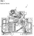
- FIG. 1 is a well-known from the prior art electro-mechanical protection device 1 with a conventional thermo-mechanical overload trip device shown schematically.
- the protective switching device 1 has a housing 2, wherein the front housing shell has been omitted in the drawing to allow a detailed insight into the structure of the protective switching device 1.
- electrical connection terminals - the input terminal 7 and the output terminal 8 - are arranged, via which the protection device 1 with external electrical leads (not shown) can be contacted.
- an actuating element 3 for manual operation - ie for switching on and off - the protective switching device 1 is arranged.
- the actuating element 3 is mechanically coupled to a switching mechanism 4 of the protective switching device 1.
- a switching contact 5 is arranged, which is actuated by means of the switching mechanism 4, that can be opened and closed.
- the protective switching device 1 has fastening means 9, which are arranged on a rear side opposite the front side on the housing 2. With the help of these fasteners 9, the protective device is on a Supporting element, such as a DIN rail (not shown), fastened.
- the protective switching device 1 has a so-called short-circuit tripping device 10. Due to the high short-circuit current, a mechanical trigger signal is generated and transmitted to the switching mechanism 4, whereby the switching mechanism 4 is triggered. As a result of this triggering the switching contact 5 is finally opened. Accordingly, the actuator 3 assumes its OFF position. Below the short circuit tripping device 20, an arc extinguishing device 6 is arranged. When the current-carrying switching contact 5 is opened, initially an arc is produced which is driven to be extinguished in the direction of the arc extinguishing device 6, where it is finally extinguished.
- the thermal overload tripping device comprises a bimetallic element 11 which is formed of two rigidly connected metal strips and extends in its longitudinal extension direction from a first distal end to a second distal end. At its first distal end, the bimetallic element 11 has a clamping point 14, via which it can be fastened in a fixed manner in the housing 2 of the protective switching device 1.
- the second distal end of the Thermobimetallements 11 is formed as a free end, which is movable relative to the attachment point when heated due to the thermal expansion of the Thermobimetallements 11.
- the bimetallic element 11 has a coupling point 15 for mechanical coupling to the switching mechanism 4. This mechanical coupling can also be realized for example by means of a bracket.
- the bimetallic element 11 bends. Since the first distal end is fixedly connected to the housing 2, this bending of the bimetallic element 11 results in a relative movement of the second distal end - and thus a coupling element of the bimetallic element Switching mechanism 4, which is mechanically coupled via the coupling point 15 with the bimetallic element 11. In this way, the thermostatic bimetallic element 11 acts on the switching mechanism 4 of the protective switching device 1 when the predefined current threshold value is exceeded in order to trigger it and to open the switching contact 5 and thus interrupt the current flow via the switching contact 5.
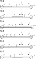
- the overload release device comprises a bimetallic element 11, which is formed from at least one metallic first strip 12 and a metallic second strip 13 extending along a longitudinal extension direction L from its first distal end (shown on the left) to its second distal end (shown on the right) extends.
- the first strip 12 and the second strip 13 represent the active component or the passive component of the thermo-bimetallic element 11, wherein both associations (the first strip 12 forms the active or the passive component) are possible in principle.
- thermo-bimetallic element 11 For example, Allen in the FIGS. 2 to 7 illustrated embodiments of the Thermobimetallements 11 is common that they have a clamping point 14 for stationary attachment in the housing 2 of the protective switching device 1 at the left end, which is the first distal end. At the right end, which corresponds to the second distal end, the embodiments of the thermo-bimetallic element 11 each have a coupling point 15 for mechanical coupling to the switching mechanism 4 of the protective switching device 1.
- the in the FIGS. 4 and 5 illustrated embodiments of the Thermobimetallements 11 have a further strip 16 which is fixedly connected to the first strip 12 in the longitudinal direction L in the region in which no second strip 13 is present.
- the further strip 16 can serve, for example, to ensure the mechanical strength of the thermo-bimetallic element 11 in this area. While in the FIGS. 2 to 5 the second strip 13 (and optionally the further strip 16) is rolled onto the first strip 12 is in the in the FIGS. 6 and 7 shown embodiments of the Thermobimetallements 11 of the second strip 13 rolled into the first strip 12, whereby the mechanical strength of the Thermobimetallements 11 is guaranteed even in the area in which no second strip 13 exists.
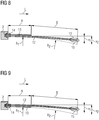
- FIGS. 8 and 9 show schematic representations of the overload tripping device according to the invention in a deflected state.
- the left end which corresponds to the first distal end of the Thermobimetallements 11, in turn, is designed as a clamping point 14 for stationary attachment in the housing 2 of the protective switching device 1.
- the right end of the Thermobimetallements 11 corresponding to the second distal end is where the coupling point 15 is arranged for coupling the Thermobimetallements 11 to the switching mechanism 4 of the protection device 1.
- the bimetallic element 11 is divided in the longitudinal direction L into two sections A and B, wherein section A has only half the length of section B.
- Section A is defined by the fact that both the first strip 12 and the second strip 13 are present here.
- the two strips 12 and 13 are firmly connected to each other, so that at a temperature increase of the bimetallic effect sets - the bimetallic element 11 curves due to temperature in the direction of the passive component.
- the curvature of the thermo-bimetallic element 11 in section A is indicated by the radius of curvature R 1 .
- the bimetallic element 11 consists only of the first strip 12, which projects beyond the end of the second strip 13. Accordingly, in this section B, due to the absence of the second strip 13, no bimetallic effect occurs.
- the deflection of the entire Thermobimetallements 11 is indicated by the deflection x 1 (deviation from the resting state).
- the dashed line which is labeled with the radius R 2 , marks the curvature of a Thermobimetallements 11, in which both the first strip 12 and the second strip 13 is guided from the clamping point 14 to the coupling point 15, so that the entire length of the bimetallic element 11 (section A plus section B) a bimetallic effect occurs.
- the associated deflection x 2 is in terms of magnitude slightly smaller than twice the value of the deflection x 1 .
- the efficiency of the use of materials can be illustrated: Although by the interaction of the first strip 12 (passive component) with the second strip 13 (active component) only in section A - and thus only over one third of the total length A + B of the bimetallic strip 11 - a bimetallic effect is achieved, the resulting curvature (with radius R 1 ) is sufficient to achieve a deflection x 1 of more than 50% of the deflection x 2 .
- bimetallic elements 11 differ in that in FIG. 8 the passive component (with the lower thermal expansion) is formed by the first strip 12, whereas in FIG. 9 the passive component is formed by the second strip 13.
- the bending behavior of the Thermobimetallelements 11 only by the interaction Depending on the active component and the passive component, and this interaction only exists in Section A in both cases, the deflection x 1 is almost identical in both cases.
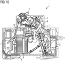
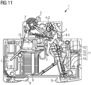
- FIGS. 10 to 12 is the inventive electro-mechanical protection device 1 shown schematically in different operating conditions.
- the individual representations essentially correspond to the representation in FIG. 1 , only in FIG. 1 used, conventional bimetallic element 11 is characterized by that from the FIGS. 2 to 9 known, inventive bimetallic element 11 has been replaced.
- the clamping point 14 is located in each case at the first distal end of the thermo-bimetallic element 11 shown below.
- the coupling point 15 is located at the upper, second distal end of the thermo-bimetallic element 11.
- the first strip 12 is designed to extend continuously from the clamping point 14 to the coupling point 15 and forms the passive component, in the direction of which the bimetallic element 11 is curved as the temperature increases.
- the second strip 13 is in the lower section A (see Figure 8 ), which adjoins the clamping point 14, firmly connected to the first strip 12, so that at a temperature increase in this section A, a bimetallic curvature effect can be realized. That in the FIGS. 10 to 12 illustrated bimetallic element 11 thus corresponds to the in the Fig.2 respectively. Figure 8 shown bimetallic element 11th
- FIG. 10 shows the thermo-mechanical overload release device in a first, "cold” operating state: the Thermobimetall element 11 is in its idle state and has no temperature-induced deformation.
- the thermo-mechanical overload release device is shown in a second, "warmed” operating state immediately before the triggering of the switching mechanism 4: the bimetallic 11 has already deformed slightly due to the temperature increase, that is curved to the right: the second distal end of the Thermobimetallements 11 touches in the representation of FIG. 11 a first end of a release lever 4-1 of the switching mechanism 4, without triggering them already.
- a Verklinkungsstelle 4-2 At another end of the trigger lever 4-1 is a Verklinkungsstelle 4-2, which in the illustration of FIG. 11 still is latched.
- FIG. 12 This shows the thermo-mechanical overload release device in a third, "hot" operating state immediately before the triggering of the switching mechanism 4.
- the bimetallic 11 is due to the progressive increase in temperature a little further curved to the right, whereby the second distal end of the Thermobimetallements 11 a force on the Trigger lever 4-1 exerts, which causes it to be rotated counterclockwise.
- the switching mechanism 4 can no longer support and falls - driven by spring forces - in together, whereby the switching contact 5 is opened and the actuating element 3 in its OFF position is spent (not shown).
Abstract
Das erfindungsgemäße elektromechanische Schutzschaltgerät (1) weist einen zwischen einer Eingangsklemme (7) und einer Ausgangsklemme (8) verlaufenden Strompfad, der seinerseits wenigstens einen von einem festen und einem beweglichen Kontaktelement gebildeten Schaltkontakt (5) aufweist, sowie eine Schaltmechanik (4) zum Öffnen und Schließen des Schaltkontakts (5) auf. Weiterhin weist das elektromechanische Schutzschaltgerät (1) eine thermomechanischen Überlastauslöseeinrichtung auf, welche ihrerseits ein Thermobimetallelement (11) aufweist, das direkt oder indirekt von einem durch den Strompfad fließenden elektrischen Strom erwärmbar ist und sich bei einem über dem Nennstrom liegenden Strom verbiegt. Das Thermobimetallelement (11) ist dabei aus zumindest einem ersten Streifen (12) und einem zweiten Streifen (13), welche fest miteinander verbunden sind, gebildet und weist eine Koppelstelle (15) zur mechanischen Ankopplung an die Schaltmechanik (4) auf. Dabei sind die beiden Streifen (12, 13) derart überlappend zueinander angeordnet, dass entlang einer Längserstreckungsrichtung des Thermobimetallelements (11) ein Ende des ersten Streifens (12) das Ende des zweiten Streifens (13) überragt, wobei die Koppelstelle (15) am Ende des ersten - über das Ende des zweiten Streifens (13) hinausragenden - Streifens (12) ausgebildet ist. Auf diese Weise können die Herstellkosten des Thermobimetallelements (11), und damit der thermischen Überlastauslöseeinrichtung sowie des elektromechanischen Schutzschaltgerätes (1), spürbar reduziert werden.The electromechanical protective switching device (1) according to the invention comprises a current path extending between an input terminal (7) and an output terminal (8), which in turn has at least one switching contact (5) formed by a fixed and a movable contact element, and a switching mechanism (4) for opening and closing the switch contact (5). Furthermore, the electromechanical protective switching device (1) on a thermo-mechanical overload trip device, which in turn has a bimetallic element (11) which is heated directly or indirectly by an electric current flowing through the current path and bends at a current lying above the rated current. The bimetallic element (11) is formed from at least one first strip (12) and a second strip (13), which are fixedly connected to each other, and has a coupling point (15) for mechanical coupling to the switching mechanism (4). In this case, the two strips (12, 13) are arranged overlapping each other such that along one longitudinal direction of the Thermobimetallements (11) one end of the first strip (12) projects beyond the end of the second strip (13), wherein the coupling point (15) at the end the first - beyond the end of the second strip (13) protruding - strip (12) is formed. In this way, the manufacturing cost of the Thermobimetallements (11), and thus the thermal overload trip device and the electro-mechanical protection device (1) can be significantly reduced.
Description
Die Erfindung betrifft ein elektromechanisches Schutzschaltgerät, beispielsweise ein Leitungsschutzschalter, Leistungsschalter oder Fehlerstromschutzschalter, das einen zwischen einer Eingangsklemme und einer Ausgangsklemme verlaufenden Strompfad mit wenigstens einem von einem festen und einem beweglichen Kontaktelement gebildeten Schaltkontakt sowie eine Schaltmechanik zum Öffnen und Schließen des Schaltkontakts aufweist. Weiterhin weist das Schutzschaltgerät eine Überlastauslöseeinrichtung auf, welche ihrerseits ein Thermobimetallelement aufweist, das direkt oder indirekt von einem durch den Strompfad fließenden elektrischen Strom erwärmbar ist und sich bei einem über dem Nennstrom liegenden Strom verbiegt, wobei das Thermobimetallelement aus zumindest einem ersten Streifen und einem zweiten Streifen gebildet ist, welche fest miteinander verbunden sind und eine Koppelstelle zur mechanischen Ankopplung an die Schaltmechanik aufweist.The invention relates to an electro-mechanical protection device, such as a circuit breaker, circuit breaker or residual current circuit breaker comprising a current path extending between an input terminal and an output terminal having at least one switching contact formed by a fixed and a movable contact element and a switching mechanism for opening and closing the switching contact. Furthermore, the protective switching device on an overload trip device, which in turn has a Thermobimetallelement which is directly or indirectly heated by a current flowing through the current path and bends at a current lying above the rated current, wherein the bimetallic element of at least a first strip and a second Strip is formed, which are firmly connected to each other and has a coupling point for mechanical coupling to the switching mechanism.
Die Erfindung betrifft weiterhin eine thermomechanische Überlastauslöseeinrichtung für ein elektromechanisches Schutzschaltgerät, beispielsweise ein Leitungsschutzschalter, Leistungsschalter oder Fehlerstromschutzschalter, gemäß dem Oberbegriff des Anspruchs 10.The invention further relates to a thermo-mechanical overload release device for an electromechanical protective switching device, for example a circuit breaker, circuit breaker or residual current circuit breaker, according to the preamble of
Elektromechanische Schutzschaltgeräte - beispielsweise Leistungsschalter, Leitungsschutzschalter oder Fehlerstromschutzschalter - werden insbesondere als Schalt- und Sicherheitselemente in elektrischen Energieversorgungsnetzen eingesetzt. Leistungsschalter sind speziell für hohe Ströme ausgelegt. Ein Leitungsschutzschalter (sogenannter LS-Schalter), welcher im englischsprachigen Raum auch als "Miniature Circuit Breaker" (MCB) bezeichnet wird, ist eine Überstromschutzeinrichtung in der Elektroinstallation und wird insbesondere im Bereich der Niederspannungsnetze eingesetzt. Leistungsschalter und Leitungsschutzschalter garantieren ein sicheres Abschalten bei Kurzschluss und schützen Verbraucher und Anlagen vor Überlast, beispielsweise vor Beschädigung elektrischer Leitungen durch zu starke Erwärmung in Folge eines zu hohen elektrischen Stromes. Leistungsschalter und Leitungsschutzschalter werden insbesondere als Schalt- und Sicherheitselemente in elektrischen Energieversorgungsnetzen eingesetzt und dienen der Überwachung sowie der Absicherung eines elektrischen Stromkreises.Electromechanical protective switching devices - such as circuit breakers, circuit breakers or residual current circuit breakers - are used in particular as switching and safety elements in electrical energy supply networks. Circuit breakers are specially designed for high currents. A circuit breaker (so-called LS switch), which is also referred to in English as "Miniature Circuit Breaker" (MCB), is an overcurrent protection device in the electrical installation and is used in particular in the field of low-voltage networks. Circuit breakers and miniature circuit breakers guarantee a safe shutdown in the event of a short circuit and protect consumers and systems from overload, for example, from damage to electrical cables due to excessive heating as a result of excessive electrical current. Circuit breakers and circuit breakers are used in particular as switching and safety elements in electrical energy supply networks and serve to monitor and secure an electrical circuit.
Ein Fehlerstromschutzschalter ist eine Schutzeinrichtung zur Gewährleistung eines Schutzes gegen einen gefährlichen Fehlerstrom in einer elektrischen Anlage. Ein derartiger Fehlerstrom, welcher auch als Differenzstrom bezeichnet wird, tritt auf, wenn ein spannungsführendes Leitungsteil einen elektrischen Kontakt gegen Erde aufweist. Dies ist beispielsweise dann der Fall, wenn eine Person ein spannungsführendes Teil einer elektrischen Anlage berührt: in diesem Fall fließt der Strom als Fehlerstrom durch den Körper der betreffenden Person gegen die Erdung ab. Zum Schutz gegen derartige Körperströme muss der Fehlerstromschutzschalter bei Auftreten eines derartigen Fehlerstroms die elektrische Anlage schnell und sicher allpolig vom Leitungsnetz trennen. Im Allgemeinen Sprachgebrauch werden anstelle des Begriffs "Fehlerstromschutzschalter" auch die Begriffe FI-Schutzschalter (kurz: FI-Schalter), Differenzstromschutzschalter (kurz: DI-Schalter) oder RCD (für "Residual Current Protective Device") gleichwertig verwendet.A residual current device is a protective device to ensure protection against a dangerous fault current in an electrical system. Such a fault current, which is also referred to as differential current, occurs when a live line part has an electrical contact with earth. This is for example the case when a person touches a live part of an electrical system: in this case, the current flows as a fault current through the body of the person against the ground. To protect against such body currents of the residual current circuit breaker must occur when such a fault current, the electrical system quickly and safely disconnect all poles from the mains. In general parlance, instead of the term "residual current circuit breaker", the terms FI circuit breaker (short: FI switch), residual current circuit breaker (short: DI switch) or RCD (for "Residual Current Protective Device") are used equally.
Zur Überwachung und Absicherung des elektrischen Stromkreises wird das Schutzschaltgerät über zwei Anschlussklemmen mit einer elektrischen Leitung des zu überwachenden Stromkreises elektrisch leitend verbunden, um bei Bedarf den elektrischen Strom in der jeweiligen Leitung zu unterbrechen. Das Schutzschaltgerät weist dabei einen Schaltkontakt mit einem ortsfesten Festkontakt sowie einem relativ dazu beweglichen Bewegkontakt auf. Der Bewegkontakt ist dabei über eine Schaltmechanik des Schutzschaltgerätes betätigbar, so dass der Schaltkontakt geöffnet und geschlossen werden kann. Auf diese Weise wird bei Auftreten eines vordefinierten Zustandes, beispielsweise eines Kurzschlusses oder einer elektrischen Überlast, der Schaltkontakt geöffnet, um den überwachten Stromkreis vom elektrischen Leitungsnetz zu trennen. Derartige Schutzschaltgeräte sind auf dem Gebiet der Niederspannungstechnik auch als Reiheneinbaugeräte bekannt.To monitor and safeguard the electrical circuit, the protective switching device is electrically connected via two terminals with an electrical line of the circuit to be monitored in order to interrupt the electrical current in the respective line when needed. The protective switching device has a switching contact with a stationary Fixed contact and a relatively movable moving contact on. The moving contact is actuated via a switching mechanism of the protective switching device, so that the switching contact can be opened and closed. In this way, when a predefined state, for example a short circuit or an electrical overload, occurs, the switching contact is opened in order to disconnect the monitored circuit from the electrical line network. Such protective switching devices are known in the field of low-voltage technology as DIN rail mounted devices.
Aus der Patentschrift
Um den Stromfluss bei Auftreten eines Kurzschlusses schnell zu unterbrechen, ist die erste Auslöseeinrichtung üblicher Weise als magnetisches Auslösesystem ausgebildet, welches eine Magnetspule sowie eine relativ dazu bewegliche Anker-Stößel-Baugruppe aufweist. Wird die Magnetspule mit dem hohen Kurzschlussstrom bestromt, so wird die Anker-Stößel-Baugruppe aufgrund der hieraus resultierenden hohen elektromagnetischen Kräfte in die Magnetspule gezogen. Diese hochdynamische Bewegung der Anker-Stößel-Baugruppe wird dazu genutzt, den Schaltkontakt zu öffnen und damit den Stromfluss über den Schaltkontakt zu unterbrechen.In order to quickly interrupt the flow of current in the event of a short circuit, the first triggering device is usually designed as a magnetic release system, which has a magnetic coil and a relatively movable armature plunger assembly. If the magnet coil is energized with the high short-circuit current, the armature plunger assembly is pulled into the magnet coil due to the resulting high electromagnetic forces. This highly dynamic movement The armature plunger assembly is used to open the switch contact and thus interrupt the flow of current through the switch contact.
Die zweite Auslöseeinrichtung ist in der Regel als thermisches Auslösesystem ausgebildet, um den Stromfluss bei Auftreten eines Überlastzustandes zu unterbrechen. Das thermische Auslösesystem weist in der Regel ein Auslöseelement aus einem Bimetall oder einer Formgedächtnislegierung auf, welches sich bei Temperaturänderung verformt. Diese Formänderung wird mittels eines mechanischen Übertragungsglieds auf die Schaltmechanik - beispielsweise auf den Auslösehebel - übertragen, wodurch die Auslösung der Schaltmechanik initiiert wird. Infolge dessen wird der Schaltkontakt geöffnet und damit der Stromfluss unterbrochen.The second triggering device is usually designed as a thermal trip system to interrupt the flow of current in the event of an overload condition. The thermal trip system usually has a tripping element made of a bimetal or a shape memory alloy, which deforms when the temperature changes. This change in shape is transmitted by means of a mechanical transmission element to the switching mechanism - for example, the trigger lever - whereby the triggering of the switching mechanism is initiated. As a result, the switching contact is opened, thus interrupting the flow of current.
Insbesondere bei preiswerten Reiheneinbaugeräten stellt das teure Material eines Thermobimetalls oder einer Formgedächtnislegierung einen erheblichen Kostenfaktor dar. Aus diesem Grund ist in der
Es ist deshalb die Aufgabe der vorliegenden Erfindung, eine kostengünstige Alternative für eine thermische Überlastauslöseeinrichtung sowie ein elektromechanisches Schutzschaltgerät mit einer derartigen thermischen Überlastauslöseeinrichtung anzugeben.It is therefore an object of the present invention to provide a cost effective alternative for a thermal overload trip device and an electro-mechanical protection device with such a thermal overload trip device.
Diese Aufgabe wird durch das elektromechanische Schutzschaltgerät sowie die thermischen Überlastauslöseeinrichtung gemäß den unabhängigen Ansprüchen gelöst. Vorteilhafte Ausgestaltungen sind Gegenstand der abhängigen Ansprüche.This object is achieved by the electro-mechanical protection device and the thermal overload trip device according to solved the independent claims. Advantageous embodiments are the subject of the dependent claims.
Das erfindungsgemäße elektromechanische Schutzschaltgerät, welches beispielsweise als Leitungsschutzschalter oder als Fehlerstromschutzschalter ausgebildet ist, weist einen zwischen einer Eingangsklemme und einer Ausgangsklemme verlaufenden Strompfad, der seinerseits wenigstens einen von einem festen und einem beweglichen Kontaktelement gebildeten Schaltkontakt aufweist, sowie eine Schaltmechanik zum Öffnen und Schließen des Schaltkontakts auf. Weiterhin weist das elektromechanische Schutzschaltgerät eine thermomechanischen Überlastauslöseeinrichtung auf, welche ihrerseits ein Thermobimetallelement aufweist, das direkt oder indirekt von einem durch den Strompfad fließenden elektrischen Strom erwärmbar ist und sich bei einem über dem Nennstrom liegenden Strom verbiegt. Das Thermobimetallelement ist dabei aus zumindest einem ersten Streifen und einem zweiten Streifen, welche fest miteinander verbunden sind, gebildet und weist eine Koppelstelle zur mechanischen Ankopplung an die Schaltmechanik auf. Dabei sind die beiden Streifen derart überlappend zueinander angeordnet, dass entlang einer Längserstreckungsrichtung des Thermobimetallelements ein Ende des ersten Streifens das Ende des zweiten Streifens überragt, wobei die Koppelstelle am Ende des ersten - über das Ende des zweiten Streifens hinausragenden - Streifens ausgebildet ist.The electromechanical protective switching device according to the invention, which is designed for example as a circuit breaker or as a residual current circuit breaker, has a running between an input terminal and an output terminal current path, which in turn has at least one switching contact formed by a fixed and a movable contact element, and a switching mechanism for opening and closing the switch contact on. Furthermore, the electromechanical protection switching device on a thermo-mechanical overload trip device, which in turn has a bimetallic element which is directly or indirectly heated by an electric current flowing through the current path and bends at a current lying above the rated current. The bimetallic element is formed from at least a first strip and a second strip, which are fixedly connected to each other, and has a coupling point for mechanical coupling to the switching mechanism. In this case, the two strips are arranged overlapping each other such that along a longitudinal direction of the Thermobimetallements one end of the first strip projects beyond the end of the second strip, wherein the coupling point at the end of the first - beyond the end of the second strip protruding - strip is formed.
Der erste und der zweite Streifen, welche das Thermobimetallelement bilden, weisen ein unterschiedliches Wärmeausdehnungsverhalten aus, so dass sich hieraus ein bimetallischer Effekt, d.h. eine temperaturbedingte Formänderung erzielen lässt. Die beiden Streifen überlappen einander und sind dabei in der Regel unterschiedlich lang, wobei die für die beiden Streifen verwendeten Materialien so gewählt sind, dass der längere erste Streifen aus dem kostengünstigeren der beiden das Thermobimetallelement bildendenden Materialien gebildet ist. Hieraus ergibt sich der Vorteil, dass der teurere erste der beiden das Thermobimetallelement bildenden Streifen deutlich kürzer ist als der günstigere zweite Streifen. Die Herstellkosten des Thermobimetallelements, und damit der thermischen Überlastauslöseeinrichtung sowie des elektromechanischen Schutzschaltgerätes, können dadurch spürbar reduziert werden.The first and the second strip, which form the bimetallic element, have a different thermal expansion behavior, so that from this a bimetallic effect, ie a temperature-induced change in shape can be achieved. The two strips overlap each other and are usually of different lengths, wherein the materials used for the two strips are chosen so that the longer first strip is formed from the lower cost of the two forming the Thermobimetallelement materials. This results in the advantage that the more expensive first of the two forming the bimetallic strip is significantly shorter than the cheaper second strip. The manufacturing costs of the Thermobimetallements, and thus the thermal overload trip device and the electro-mechanical protection device, can be significantly reduced.
In einer vorteilhaften Weiterbildung des Schutzschaltgerätes erstreckt sich das Thermobimetallelement in seiner Längserstreckungsrichtung von einem ersten distalen Ende zu einem zweiten distalen Ende, wobei am ersten distalen Ende eine Einspannstelle zur ortsfesten Fixierung des Thermobimetallelements in einem Gehäuse des Schutzschaltgerätes angeordnet ist, und wobei die Koppelstelle am zweiten distalen Ende angeordnet ist.In an advantageous development of the protective switching device, the bimetallic element extends in its longitudinal extension direction from a first distal end to a second distal end, wherein at the first distal end a clamping point for stationary fixation of the thermostatic element is arranged in a housing of the protective switching device, and wherein the coupling point on the second distal end is arranged.
In einer weiteren vorteilhaften Weiterbildung des Schutzschaltgerätes erstreckt sich der erste Streifen vom ersten distalen Ende bis zum zweiten distalen Ende des Thermobimetallelements.In a further advantageous embodiment of the protective switching device, the first strip extends from the first distal end to the second distal end of the Thermobimetallements.
In einer weiteren vorteilhaften Weiterbildung des Schutzschaltgerätes ist der zweite Streifen zwischen dem ersten distalen Ende und dem zweiten distalen Ende angeordnet.In a further advantageous development of the protective switching device, the second strip is arranged between the first distal end and the second distal end.
In einer weiteren vorteilhaften Weiterbildung des Schutzschaltgerätes ist der zweite Streifen mittig zum ersten Streifen angeordnet.In a further advantageous development of the protective switching device, the second strip is arranged centrally to the first strip.
Da die Koppelstelle zur mechanischen Ankopplung des Thermobimetallelements an die Schaltmechanik erfindungsgemäß am Ende des ersten Streifens, welcher über das Ende des zweiten Streifens hinausragt, ausgebildet, d.h. angeordnet ist, stellt dieses Ende des ersten Streifens das zweite distale Ende des Thermobimetallelements dar. Das erste distale Ende des Thermobimetallelements wird hingegen durch die Einspannstelle zur ortsfesten Fixierung des Thermobimetallelements im Gehäuse des Schutzschaltgerätes gebildet. Damit erstreckt sich der erste Streifen vom ersten distalen Ende zum zweiten distalen Ende des Thermobimetallelements. Hieraus ergibt sich der Vorteil, dass im Gegensatz zu der in der Druckschrift
Durch die Anordnung des zweiten Streifens relativ zum ersten Streifen - beispielsweise mittig, außermittig oder bündig zum distalen ersten Ende des Thermobimetallelements - ist das temperaturbedingte, geometrische Krümmungsverhalten des Thermobimetallelements spezifisch variierbar und damit an verschiedene Einsatzbedingungen anpassbar. Unter dem Begriff "mittig" ist dabei im Wesentlichen mittig zu verstehen, so dass der erste Streifen auch im Bereich des ersten distalen Endes, welches die Einspannstelle des Thermobimetallelements bildet, über den zweiten Streifen hinausragt.By arranging the second strip relative to the first strip-for example centrally, eccentrically or flush with the distal first end of the thermo-bimetallic element-the temperature-related, geometric curvature behavior of the thermo-bimetallic element can be specifically varied and thus adapted to different operating conditions. The term "centered" is to be understood essentially centrally, so that the first strip protrudes beyond the second strip also in the region of the first distal end, which forms the clamping point of the thermobimetal element.
In einer weiteren vorteilhaften Weiterbildung des Schutzschaltgerätes ist der erste Streifen durch die aktive Komponente des Thermobimetallelements gebildet.In a further advantageous development of the protective switching device, the first strip is formed by the active component of the thermo-bimetallic element.
In einer weiteren vorteilhaften Weiterbildung des Schutzschaltgerätes ist der erste Streifen durch die die passive Komponente des Thermobimetallelements gebildet.In a further advantageous development of the protective switching device, the first strip is formed by the passive component of the Thermobimetallements.
Der Grundtyp eines Thermobimetallelements ist in der Regel aus zwei Metallstreifen unterschiedlichen Materials gebildet, welche bei einer vordefinierten Temperatur die gleiche Länge aufweisen und fest miteinander verbunden sind. Die verwendeten Materialien unterscheiden sich jedoch deutlich hinsichtlich ihres Temperaturausdehnungsverhaltens, so dass eine Temperaturänderung zu einer unterschiedlichen Längenänderung führt. Der Streifen mit der größeren thermischen Ausdehnung wird dabei als Aktivkomponente, der Streifen mit der geringeren thermischen Ausdehnung als Passivkomponente des Thermobimetallelements bezeichnet. Da die beiden Streifen fest miteinander verbunden sind, können sie sich bei Erwärmung nicht mehr unabhängig voneinander ausdehnen: die Aktivkomponente wird durch die Passivkomponente an der Ausdehnung behindert, wodurch das Thermobimetallelement in Richtung der Passivkomponente gekrümmt wird.The basic type of Thermobimetallements is usually formed of two metal strips of different material, which have the same length at a predefined temperature and are firmly connected. The used However, materials differ significantly in terms of their thermal expansion behavior, so that a change in temperature leads to a different change in length. The strip with the greater thermal expansion is referred to as the active component, the strip with the lower thermal expansion as the passive component of the Thermobimetallements. Since the two strips are firmly joined together, they can no longer expand independently when heated: the active component is obstructed by the passive component at the extension, causing the bimetallic element to curve toward the passive component.
Für die Aktivkomponente können beispielsweise Manganlegierungen mit hohem Kupfer- und Nickelanteil (z.B. MnCu18Ni10 oder MnNi16Cu10), korrosionsbeständiger Stahl mit hohem Nickelanteil (z.B. FeNi20Mn6, FeNi14Mn7 oder FeNi22Cr3) oder Nickel-werkstoffe eingesetzt werden. All diesen Legierungen weisen eine hohe thermische Ausdehnung auf. Für die Passivkomponente kommen beispielsweise Eisen-Nickel-Werkstoffe (z.B. FeNi36, FeNi38, FeNi39, FeNi42, FeNi46 oder FeNi32Co6), korrosionsbeständige Stähle mit Chrom- oder Nickel-Chrom-Kobalt-Bestandteilen oder Kupfer-Nickel-Legierungen wie CuNi44Mn1 zum Einsatz, die allesamt ein vergleichsweise niedriges thermisches Ausdehnungsverhalten aufweisen.For the active component, for example, high copper and nickel manganese alloys (e.g., MnCu18Ni10 or MnNi16Cu10), high nickel corrosion-resistant steel (e.g., FeNi20Mn6, FeNi14Mn7, or FeNi22Cr3) or nickel materials may be employed. All of these alloys have a high thermal expansion. For the passive component, for example, iron-nickel materials (eg FeNi36, FeNi38, FeNi39, FeNi42, FeNi46 or FeNi32Co6), corrosion-resistant steels with chromium or nickel-chromium-cobalt constituents or copper-nickel alloys such as CuNi44Mn1 are used all have a comparatively low thermal expansion behavior.
Die Frage, ob der erste Streifen durch die aktive Komponente oder die passive Komponente des Thermobimetallelements gebildet ist, wird neben den rein technischen Materialeigenschaften letztendlich auch dahingehend zu beurteilen sein, für welche der beiden Komponenten das teurere Material verwendet werden wird. Auf diese Weise können die Materialkosten, und damit die Herstellkosten des Thermobimetallelements, deutlich reduziert werden.The question of whether the first strip is formed by the active component or the passive component of the Thermobimetallements, in addition to the purely technical material properties ultimately be judged as to which of the two components, the more expensive material will be used. In this way, the material costs, and thus the manufacturing costs of the Thermobimetallements be significantly reduced.
In einer weiteren vorteilhaften Weiterbildung des Schutzschaltgerätes weist das Thermobimetallelement zumindest einen weiteren Streifen auf, welcher zumindest mit dem ersten Streifen zumindest abschnittsweise fest verbunden ist.In a further advantageous development of the protective switching device, the bimetallic element has at least one further strip which is at least partially firmly connected at least with the first strip.
Bei dem weiteren Streifen kann es sich beispielsweise um eine Zwischenschicht zwischen der aktiven Komponente und der passiven Komponente des Thermobimetallelements handeln. Solche Zwischenschichten, auch als Zwischenlagen bezeichnet, werden verwendet, um beispielsweise die technischen Eigenschaften des Thermobimetallelements, z.B. dessen Festigkeit, gezielt zu beeinflussen, oder auch um eine stabile mechanische Verbindung zwischen der der aktiven Komponente und der passiven Komponente des Thermobimetallelements zu erreichen.The further strip may be, for example, an intermediate layer between the active component and the passive component of the thermobimetal element. Such intermediate layers, also referred to as intermediate layers, are used, for example, for the technical properties of the thermobimetal element, e.g. its strength to affect targeted, or even to achieve a stable mechanical connection between the active component and the passive component of the Thermobimetallements.
Es ist jedoch auch möglich, dass der weitere Streifen als Trägerschicht mit einem Bereich des ersten Streifens, welcher das Ende des zweiten Streifens überragt, verbunden wird, um dort dem ersten Streifen eine ausreichende Stabilität zu verleihen. Dies ist insbesondere dann vorteilhaft, wenn der weitere Streifen aus einem deutlich günstigeren Material als der erste Streifen gebildet ist.However, it is also possible that the further strip is connected as a carrier layer with a portion of the first strip, which projects beyond the end of the second strip, in order to give the first strip a sufficient stability. This is particularly advantageous when the further strip is formed from a material significantly cheaper than the first strip.
In einer weiteren vorteilhaften Weiterbildung des Schutzschaltgerätes sind die Streifen durch Schweißen und/oder Walzen miteinander verbunden.In a further advantageous development of the protective switching device, the strips are connected to one another by welding and / or rolling.
Da die einzelnen Komponenten eines Thermobimetalls aufgrund ihrer geringen Dicke in der Regel nicht in der gewünschten Fertigungsdicke miteinander verbunden werden können, werden zunächst dickere Schichten miteinander verbunden und anschließend auf ihre Fertigungsdicke gewalzt. Zur Herstellung des zu walzenden Schichtverbundwerkstoffs für ein Thermobimetall können verschiedene Verfahren eingesetzt werden, beispielsweise das Angießen einer flüssigen Komponente an eine feste Komponente, das Warmpressschweißen oder das Warmwalzplattieren. Die jeweilige Verfahrensart hängt dabei unter anderem von den gewählten, miteinander zu verbindenden Werkstoffen ab. Ferner kann der zweite Streifen sowohl auf den ersten Streifen aufgewalzt, als auch in den ersten Streifen eingewalzt werden.Since the individual components of a bimetallic strip usually can not be connected to one another in the desired production thickness due to their small thickness, first thicker layers are joined together and then rolled to their production thickness. Various methods can be used to produce the layered composite material for a bimetallic strip to be rolled, for example the casting of a liquid component onto a solid component, hot-pressure welding or hot-roll cladding. The type of process depends, among other things, on the materials selected to be joined together. Furthermore, the second strip can be applied both to the Rolled first strip, as well as rolled into the first strip.
Die erfindungsgemäße thermomechanische Überlastauslöseeinrichtung für ein elektromechanisches Schutzschaltgerät, beispielsweise für einen Leitungsschutzschalter oder einen Fehlerstromschutzschalter, mit einem Thermobimetallelement, welches direkt oder indirekt von einem durch den Strompfad fließenden elektrischen Strom erwärmbar ist und sich bei einem über dem Nennstrom liegenden Strom verbiegt, ist dadurch gekennzeichnet, dass die thermomechanische Überlastauslöseeinrichtung wie vorstehend beschrieben aufgebaut ist.The thermo-mechanical overload release device according to the invention for an electromechanical protective switching device, for example for a circuit breaker or a fault current circuit breaker, with a bimetallic element which can be heated directly or indirectly by an electric current flowing through the current path and bends at a current lying above the rated current, characterized in that the thermo-mechanical overload release device is constructed as described above.
Hinsichtlich der Vorteile der thermomechanische Überlastauslöseeinrichtung wird auf die vorstehend beschriebenen Vorteile des elektromechanischen Schutzschaltgerätes verwiesen.With regard to the advantages of the thermo-mechanical overload tripping device, reference is made to the advantages of the electromechanical protective switching device described above.
Im Folgenden werden Ausführungsbeispiele des elektromechanischen Schutzschaltgerätes sowie der Überlastauslöseeinrichtung unter Bezug auf die beigefügten Figuren näher erläutert. In den Figuren sind:
- Figur 1
- eine schematische Darstellung eines aus dem Stand der Technik bekannten elektromechanischen Schutzschaltgerätes;
Figuren 2bis 7- schematische Darstellungen unterschiedlicher Ausführungsformen der erfindungsgemäßen Überlastauslöseeinrichtung in einem Ruhezustand;
Figuren 8 und 9- schematische Darstellungen der Überlastauslöseeinrichtung in einem ausgelenkten Zustand;
Figuren 10bis 12- schematische Darstellungen des erfindungsgemäßen elektromechanischen Schutzschaltgerätes in verschiedenen Betriebszuständen;
- FIG. 1
- a schematic representation of a known from the prior art electro-mechanical protection device;
- FIGS. 2 to 7
- schematic representations of different embodiments of the overload trip device according to the invention in a resting state;
- FIGS. 8 and 9
- schematic representations of the overload trip device in a deflected state;
- FIGS. 10 to 12
- schematic representations of the electromechanical protective device according to the invention in different operating states;
In den verschiedenen Figuren der Zeichnung sind gleiche Teile stets mit dem gleichen Bezugszeichen versehen. Die Beschreibung gilt für alle Zeichnungsfiguren, in denen das entsprechende Teil ebenfalls zu erkennen ist.In the various figures of the drawing, like parts are always provided with the same reference numerals. The description applies to all drawing figures in which the corresponding part can also be recognized.
In
Im Falle eines Kurzschlusses weist das Schutzschaltgerät 1 eine sog. Kurzschluss-Auslösevorrichtung 10 auf. Durch den hohen Kurzschlussstrom wird ein mechanisches Auslösesignal erzeugt und auf die Schaltmechanik 4 übertragen, wodurch die Schaltmechanik 4 ausgelöst wird. Infolge dieser Auslösung wird schließlich der Schaltkontakt 5 geöffnet. Entsprechend nimmt das Betätigungselement 3 seine OFF-Position ein. Unterhalb der Kurzschluss-Auslösevorrichtung 20 ist eine Lichtbogen-Löschvorrichtung 6 angeordnet. Beim Öffnen des stromdurchflossenen Schaltkontakts 5 entsteht zunächst ein Lichtbogen, der zur Löschung in Richtung der Lichtbogen-Löschvorrichtung 6 getrieben wird, wo er schließlich gelöscht wird.In the case of a short circuit, the protective switching device 1 has a so-called short-
Für den Fall einer elektrischen Überlast weist das Schutzschaltgerät 1 eine thermische Überlastauslöseeinrichtung auf, welche bei dem in
Wird ein für eine Überlastauslösung maßgeblicher, vordefinierter Stromschwellwert überschritten, so verbiegt sich das Thermobimetallelement 11. Da das erste distale Ende ortsfest mit dem Gehäuse 2 verbunden ist, führt dieses Verbiegen des Thermobimetallelement 11 zu einer Relativbewegung des zweiten distalen Endes - und damit eines Koppelelements der Schaltmechanik 4, welches über die Koppelstelle 15 mit dem Thermobimetallelement 11 mechanisch gekoppelt ist. Auf diese Weise wirkt das Thermobimetallelement 11 bei Überschreiten des vordefinierten Stromschwellwertes auf die Schaltmechanik 4 des Schutzschaltgerätes 1 ein, um diese auszulösen und den Schaltkontakt 5 zu öffnen und damit den Stromfluss über den Schaltkontakt 5 zu unterbrechen.If a predefined current threshold decisive for overload tripping is exceeded, then the
In den
Allen in den
Die in den
Die
Das Thermobimetallelement 11 ist in der Längserstreckungsrichtung L in zwei Abschnitte A und B unterteilt, wobei Abschnitt A nur die Hälfte der Länge von Abschnitt B aufweist. Abschnitt A ist dadurch definiert, dass hier sowohl der erste Streifen 12 als auch der zweite Streifen 13 vorliegen. Die beiden Streifen 12 und 13 sind fest miteinander verbunden, so dass sich bei einer Temperaturerhöhung der bimetallische Effekt einstellt - das Thermobimetallelement 11 krümmt sich temperaturbedingt in Richtung der Passivkomponente. Die Krümmung des Thermobimetallelements 11 in Abschnitt A ist dabei durch den Krümmungsradius R1 angegeben. In Abschnitt B hingegen besteht das Thermobimetallelement 11 nur aus dem ersten Streifen 12, welcher über das Ende des zweiten Streifens 13 hinausragt. In diesem Abschnitt B tritt infolge des Fehlens des zweiten Streifens 13 dementsprechend kein bimetallischer Effekt auf. Die Auslenkung des gesamten Thermobimetallelements 11 ist durch die Auslenkung x1 (Abweichung vom Ruhezustand) angegeben.The
Die gestrichelte Linie, welche mit dem Radius R2 beschriftet ist, markiert die Krümmung eines Thermobimetallelements 11, bei dem sowohl der erste Streifen 12 als auch der zweite Streifen 13 von der Einspannstelle 14 bis zur Koppelstelle 15 geführt ist, so dass sich die gesamte Länge des Thermobimetallelements 11 (Abschnitt A plus Abschnitt B) ein bimetallischer Effekt auftritt. Die hierzu gehörige Auslenkung x2 ist betragsmäßig etwas kleiner als der doppelte Wert der Auslenkung x1. Anhand dieser Darstellungen lässt sich die Effizienz des Materialeinsatzes verdeutlichen: Obwohl durch das Zusammenwirken des ersten Streifens 12 (passive Komponente) mit dem zweiten Streifen 13 (aktive Komponente) lediglich in Abschnitt A - und damit lediglich über ein Drittel der Gesamtlänge A+B des Thermobimetalls 11 - ein bimetallischer Effekt erzielt wird, reicht die daraus resultierende Krümmung (mit Radius R1) dazu aus, eine Auslenkung x1 von mehr als 50% der Auslenkung x2 zu erzielen.The dashed line, which is labeled with the radius R 2 , marks the curvature of a
Die in den
In den
Die Auslösung der Schaltmechanik 4 ist schließlich in
Die technische Gestaltung der erfindungsgemäßen Überlastauslöseeinrichtung ist nicht auf die dargestellten, bevorzugten Ausführungsformen beschränkt. Es sind auch beliebige Kombinationen bevorzugter Ausführungsformen sowie einzelner Ausgestaltungsmerkmale möglich, sofern sie sich nicht gegenseitig ausschließen.The technical design of the overload trip device according to the invention is not limited to the illustrated, preferred embodiments. There are also any combinations of preferred embodiments and individual design features possible, unless they are mutually exclusive.
- 11
- SchutzschaltgerätProtection device
- 22
- Gehäusecasing
- 33
- Betätigungselementactuator
- 44
-
Schaltmechanik
4-1 Auslösehebel
4-2 Verklinkungsstelleswitching mechanism
4-1 release lever
4-2 latching point - 55
- Schaltkontaktswitching contact
- 66
- Lichtbogen-LöschvorrichtungArc-extinguishing device
- 77
- Eingangsklemmeinput terminal
- 88th
- Ausgangsklemmeoutput terminal
- 99
- Befestigungsmittelfastener
- 1010
- Kurzschluss-AuslösevorrichtungShort trip device
- 1111
- ThermobimetallelementThermobimetallelement
- 1212
- erster Streifenfirst strip
- 1313
- zweiter Streifensecond strip
- 1414
- Einspannstelleclamping
- 1515
- Koppelstellecoupling point
- 1616
- weiterer Streifenanother strip
- AA
- Abschnitt ASection A
- BB
- Abschnitt BSection B
- R1 R 1
- Radius R1 Radius R 1
- R2 R 2
- Radius R2 Radius R 2
- x1 x 1
- Auslenkung x1 Deflection x 1
- x2 x 2
- Auslenkung x2 Deflection x 2
- LL
- LängserstreckungsrichtungLongitudinal extension
Claims (10)
dadurch gekennzeichnet,
characterized,
dadurch gekennzeichnet,
dass der erste Streifen (12) sich vom ersten distalen Ende bis zum zweiten distalen Ende erstreckt.Protective switching device (1) according to claim 2,
characterized,
in that the first strip (12) extends from the first distal end to the second distal end.
dass der zweite Streifen (13) zwischen dem ersten distalen Ende und dem zweiten distalen Ende angeordnet ist.Protective switching device (1) according to one of claims 2 or 3, characterized
in that the second strip (13) is arranged between the first distal end and the second distal end.
dadurch gekennzeichnet,
dass der zweite Streifen (13) mittig zum ersten Streifen (12) angeordnet ist.Protective switching device (1) according to one of the preceding claims,
characterized,
that the second strip (13) centrally to the first strip (12) is arranged.
dadurch gekennzeichnet,
dass der erste Streifen (12) durch die aktive Komponente des Thermobimetallelements (11) gebildet ist.Protective switching device (1) according to one of the preceding claims,
characterized,
that the first strip (12) through the active component of the Thermobimetallelements (11) is formed.
dadurch gekennzeichnet,
dass der erste Streifen (12) durch die passive Komponente des Thermobimetallelements gebildet ist.Protective switching device (1) according to one of the preceding claims,
characterized,
in that the first strip (12) is formed by the passive component of the thermobimetal element.
dadurch gekennzeichnet,
dass das Thermobimetallelement (11) zumindest einen weiteren Streifen (16) aufweist, welcher zumindest mit dem ersten Streifen (12) zumindest abschnittsweise fest verbunden ist.Protective switching device (1) according to one of the preceding claims,
characterized,
in that the bimetallic element (11) has at least one further strip (16) which is firmly connected at least in sections at least to the first strip (12).
dadurch gekennzeichnet,
dass die Streifen (12, 13, 16) durch Schweißen und/oder Walzen miteinander verbunden sind.Protective switching device (1) according to one of the preceding claims,
characterized,
in that the strips (12, 13, 16) are joined together by welding and / or rolling.
Applications Claiming Priority (1)
| Application Number | Priority Date | Filing Date | Title |
|---|---|---|---|
| DE102016210485.3A DE102016210485A1 (en) | 2016-06-14 | 2016-06-14 | Electromechanical protection device with an overload release device |
Publications (1)
| Publication Number | Publication Date |
|---|---|
| EP3258231A1 true EP3258231A1 (en) | 2017-12-20 |
Family
ID=58778962
Family Applications (1)
| Application Number | Title | Priority Date | Filing Date |
|---|---|---|---|
| EP17173046.8A Withdrawn EP3258231A1 (en) | 2016-06-14 | 2017-05-26 | Electromechanical protective switching device with an overload trigger device |
Country Status (3)
| Country | Link |
|---|---|
| EP (1) | EP3258231A1 (en) |
| CN (2) | CN107507745A (en) |
| DE (1) | DE102016210485A1 (en) |
Cited By (1)
| Publication number | Priority date | Publication date | Assignee | Title |
|---|---|---|---|---|
| CN112768315A (en) * | 2020-12-31 | 2021-05-07 | 上海佳岚智能科技有限公司 | Intelligent miniature circuit breaker and method |
Families Citing this family (1)
| Publication number | Priority date | Publication date | Assignee | Title |
|---|---|---|---|---|
| CN117144274B (en) * | 2023-10-30 | 2024-02-02 | 武汉科技大学 | Preparation method of nickel-titanium alloy and overload automatic circuit breaking protector |
Citations (4)
| Publication number | Priority date | Publication date | Assignee | Title |
|---|---|---|---|---|
| US2171344A (en) * | 1937-01-13 | 1939-08-29 | Automatic Control Corp | Bimetallic strip |
| DE102004040288B4 (en) | 2004-08-19 | 2007-09-20 | Siemens Ag | Circuit breaker with short-circuit and overload trip indication and corresponding procedure |
| WO2013154801A1 (en) * | 2012-04-13 | 2013-10-17 | Siemens Industry, Inc. | Low tripping level circuit breakers, tripping units, and methods |
| DE102012013433B4 (en) | 2012-07-05 | 2014-04-17 | Abb Ag | Installation switching device with a thermomechanical converter |
Family Cites Families (14)
| Publication number | Priority date | Publication date | Assignee | Title |
|---|---|---|---|---|
| SE363696B (en) * | 1972-06-07 | 1974-01-28 | Asea Ab | |
| DE2302163A1 (en) * | 1973-01-17 | 1974-07-18 | Kovopol N P | MINIATURE THERMOSTAT WITH INCREASED SENSITIVITY |
| DE2625716C3 (en) * | 1976-06-09 | 1979-10-11 | E.G.O. Elektro-Geraete Blanc U. Fischer, 7519 Oberderdingen | Power control unit |
| CN1039754C (en) * | 1993-08-03 | 1998-09-09 | 奥特控制有限公司 | Improvements relating to electric switches |
| US5550525A (en) * | 1994-07-19 | 1996-08-27 | Therm-0-Disc, Incorporated | Switch with bimetallic element |
| CH691559A5 (en) * | 1997-04-21 | 2001-08-15 | Asulab Sa | magnetic micro-switch and its production process. |
| CN201315296Y (en) * | 2008-09-28 | 2009-09-23 | 无锡唯特电气技术有限公司 | Integrated thermal tripper bracket of micro circuit breaker |
| JP5152102B2 (en) * | 2009-03-27 | 2013-02-27 | 富士電機機器制御株式会社 | Thermal overload relay |
| CN101923987B (en) * | 2009-06-09 | 2013-06-12 | 科都电气有限公司 | Improved breaker |
| DE102010017741B4 (en) * | 2010-07-05 | 2012-05-16 | Stego-Holding Gmbh | bimetallic |
| CN103187213B (en) * | 2011-12-29 | 2015-03-25 | 上海良信电器股份有限公司 | Movement mechanism of thermal overload relay |
| CN203367175U (en) * | 2013-08-13 | 2013-12-25 | 德力西电气有限公司 | Thermal tripping device support |
| KR20150044746A (en) * | 2013-10-17 | 2015-04-27 | 엘에스산전 주식회사 | Trip device for curcuit breaker |
| KR101529591B1 (en) * | 2013-12-19 | 2015-06-17 | 엘에스산전 주식회사 | Trip device for curcuit breaker |
-
2016
- 2016-06-14 DE DE102016210485.3A patent/DE102016210485A1/en not_active Withdrawn
-
2017
- 2017-05-26 EP EP17173046.8A patent/EP3258231A1/en not_active Withdrawn
- 2017-06-14 CN CN201710447542.7A patent/CN107507745A/en active Pending
- 2017-06-14 CN CN202110478995.2A patent/CN113284772A/en active Pending
Patent Citations (4)
| Publication number | Priority date | Publication date | Assignee | Title |
|---|---|---|---|---|
| US2171344A (en) * | 1937-01-13 | 1939-08-29 | Automatic Control Corp | Bimetallic strip |
| DE102004040288B4 (en) | 2004-08-19 | 2007-09-20 | Siemens Ag | Circuit breaker with short-circuit and overload trip indication and corresponding procedure |
| WO2013154801A1 (en) * | 2012-04-13 | 2013-10-17 | Siemens Industry, Inc. | Low tripping level circuit breakers, tripping units, and methods |
| DE102012013433B4 (en) | 2012-07-05 | 2014-04-17 | Abb Ag | Installation switching device with a thermomechanical converter |
Cited By (1)
| Publication number | Priority date | Publication date | Assignee | Title |
|---|---|---|---|---|
| CN112768315A (en) * | 2020-12-31 | 2021-05-07 | 上海佳岚智能科技有限公司 | Intelligent miniature circuit breaker and method |
Also Published As
| Publication number | Publication date |
|---|---|
| DE102016210485A1 (en) | 2017-12-14 |
| CN113284772A (en) | 2021-08-20 |
| CN107507745A (en) | 2017-12-22 |
Similar Documents
| Publication | Publication Date | Title |
|---|---|---|
| EP2980822B1 (en) | Protective switch device and magnetic yoke | |
| DE102015213375B4 (en) | Thermal overload release device and protective switching device | |
| DE3021867A1 (en) | SELF-SWITCH | |
| DE102013211539A1 (en) | Switching mechanism for electromechanical protection switching device, has contour portions that are arranged such that enlarged opening stroke distance is realized in main phase of enlarged impact impulse lever and in auxiliary phase | |
| EP3525227B1 (en) | Mains voltage-independent ground fault electrical switching apparatus and assembly method | |
| EP3602599B1 (en) | Overcurrent protection device | |
| EP3258231A1 (en) | Electromechanical protective switching device with an overload trigger device | |
| DE102012013433B4 (en) | Installation switching device with a thermomechanical converter | |
| DE102012202153A1 (en) | Thermomagnetic release for small current ranges | |
| EP2437354A1 (en) | Low voltage switching device with a connection clamp assembly | |
| DE102016203506B4 (en) | Tripping device and electromechanical circuit breaker | |
| EP0028389B1 (en) | Low voltage-protective line switch | |
| DE102011008829B4 (en) | Service switching device | |
| DE102008026813A1 (en) | Electric selective auto switch | |
| EP3293751B1 (en) | Operating mechanism for a low voltage circuit breaker | |
| DE102012011063A1 (en) | Electrical switching device e.g. generator circuit breaker, has trip coil traversed by current to be monitored, and rod-shaped tripping armature made of material exhibiting thermal effect and magnetic shape memory effect | |
| DE102011008834A1 (en) | Service switching device | |
| DE102016203508B4 (en) | Tripping device and electromechanical circuit breaker | |
| DE102012021668A1 (en) | Device for protecting an AC supplied with an alternating current, which can be integrated in a contactor | |
| DE102014204026A1 (en) | Thermal tripping shaft and method for adjusting a distance between a bimetallic element and the thermal tripping shaft | |
| EP2680293B1 (en) | Release mechanism | |
| EP2824689B1 (en) | Dynamic actuator and electric installation device with a dynamic trigger | |
| DE102011079593B4 (en) | Electromechanical circuit breaker | |
| DE69833637T2 (en) | Selective release for circuit breakers | |
| DE102012018456A1 (en) | Bimetallic arrangement for e.g. main circuit breaker, has thermal bimetallic strip including strip portions that are controlled depending upon incident by overload current or residual current, for selective behavior of switching device |
Legal Events
| Date | Code | Title | Description |
|---|---|---|---|
| PUAI | Public reference made under article 153(3) epc to a published international application that has entered the european phase |
Free format text: ORIGINAL CODE: 0009012 |
|
| STAA | Information on the status of an ep patent application or granted ep patent |
Free format text: STATUS: THE APPLICATION HAS BEEN PUBLISHED |
|
| AK | Designated contracting states |
Kind code of ref document: A1 Designated state(s): AL AT BE BG CH CY CZ DE DK EE ES FI FR GB GR HR HU IE IS IT LI LT LU LV MC MK MT NL NO PL PT RO RS SE SI SK SM TR |
|
| AX | Request for extension of the european patent |
Extension state: BA ME |
|
| STAA | Information on the status of an ep patent application or granted ep patent |
Free format text: STATUS: REQUEST FOR EXAMINATION WAS MADE |
|
| 17P | Request for examination filed |
Effective date: 20180618 |
|
| RBV | Designated contracting states (corrected) |
Designated state(s): AL AT BE BG CH CY CZ DE DK EE ES FI FR GB GR HR HU IE IS IT LI LT LU LV MC MK MT NL NO PL PT RO RS SE SI SK SM TR |
|
| STAA | Information on the status of an ep patent application or granted ep patent |
Free format text: STATUS: EXAMINATION IS IN PROGRESS |
|
| 17Q | First examination report despatched |
Effective date: 20210317 |
|
| STAA | Information on the status of an ep patent application or granted ep patent |
Free format text: STATUS: EXAMINATION IS IN PROGRESS |
|
| STAA | Information on the status of an ep patent application or granted ep patent |
Free format text: STATUS: THE APPLICATION IS DEEMED TO BE WITHDRAWN |
|
| 18D | Application deemed to be withdrawn |
Effective date: 20221201 |