EP2824689B1 - Dynamic actuator and electric installation device with a dynamic trigger - Google Patents
Dynamic actuator and electric installation device with a dynamic trigger Download PDFInfo
- Publication number
- EP2824689B1 EP2824689B1 EP14170941.0A EP14170941A EP2824689B1 EP 2824689 B1 EP2824689 B1 EP 2824689B1 EP 14170941 A EP14170941 A EP 14170941A EP 2824689 B1 EP2824689 B1 EP 2824689B1
- Authority
- EP
- European Patent Office
- Prior art keywords
- contact element
- movable contact
- switching device
- release
- switching
- Prior art date
- Legal status (The legal status is an assumption and is not a legal conclusion. Google has not performed a legal analysis and makes no representation as to the accuracy of the status listed.)
- Active
Links
Images

Classifications
-
- H—ELECTRICITY
- H01—ELECTRIC ELEMENTS
- H01H—ELECTRIC SWITCHES; RELAYS; SELECTORS; EMERGENCY PROTECTIVE DEVICES
- H01H71/00—Details of the protective switches or relays covered by groups H01H73/00 - H01H83/00
- H01H71/10—Operating or release mechanisms
- H01H71/12—Automatic release mechanisms with or without manual release
- H01H71/14—Electrothermal mechanisms
-
- H—ELECTRICITY
- H01—ELECTRIC ELEMENTS
- H01H—ELECTRIC SWITCHES; RELAYS; SELECTORS; EMERGENCY PROTECTIVE DEVICES
- H01H71/00—Details of the protective switches or relays covered by groups H01H73/00 - H01H83/00
- H01H71/10—Operating or release mechanisms
- H01H71/12—Automatic release mechanisms with or without manual release
- H01H71/42—Induction-motor, induced-current, or electrodynamic release mechanisms
- H01H71/43—Electrodynamic release mechanisms
-
- H—ELECTRICITY
- H01—ELECTRIC ELEMENTS
- H01H—ELECTRIC SWITCHES; RELAYS; SELECTORS; EMERGENCY PROTECTIVE DEVICES
- H01H71/00—Details of the protective switches or relays covered by groups H01H73/00 - H01H83/00
- H01H71/10—Operating or release mechanisms
- H01H71/12—Automatic release mechanisms with or without manual release
- H01H71/24—Electromagnetic mechanisms
- H01H71/2418—Electromagnetic mechanisms combined with an electrodynamic current limiting mechanism
- H01H2071/2427—Electromagnetic mechanisms combined with an electrodynamic current limiting mechanism with blow-off movement tripping mechanism, e.g. electrodynamic effect on contacts trips the traditional trip device before it can unlatch the spring mechanism by itself
-
- H—ELECTRICITY
- H01—ELECTRIC ELEMENTS
- H01H—ELECTRIC SWITCHES; RELAYS; SELECTORS; EMERGENCY PROTECTIVE DEVICES
- H01H71/00—Details of the protective switches or relays covered by groups H01H73/00 - H01H83/00
- H01H71/10—Operating or release mechanisms
- H01H71/50—Manual reset mechanisms which may be also used for manual release
- H01H71/52—Manual reset mechanisms which may be also used for manual release actuated by lever
- H01H71/526—Manual reset mechanisms which may be also used for manual release actuated by lever the lever forming a toggle linkage with a second lever, the free end of which is directly and releasably engageable with a contact structure
Definitions
- the invention relates to a dynamic release for an electrical installation switching device, in particular a circuit breaker, and an electrical switching device with an aforementioned dynamic release.
- circuit breakers or circuit breakers.
- the installations are usually protected against electrical faults by means of a thermal release and an electromagnetic release, which in the event of an electrical fault during operation of the circuit breaker act on a circuit breaker of the circuit breaker such that it unlatches (triggers) and a automatic interruption of the current path leads. That current path extends over a conductor section, which is typically routed through the circuit breaker, and is electrically interruptible at a disconnection point by the switching mechanism.
- Verklinkungsstelle a switching lock unlatched, usually a movable contact element at the separation point along a path of a stationary contact element is pivoted away and thus the current path safely and reliably interrupted until the targeted restart of the circuit breaker.
- a triggering of the switching mechanism in case of electrical overload with the thermal release takes place when the predetermined nominal value of the current flowing through the circuit breaker current is exceeded considerably longer time.
- the time to trip depends on the magnitude of the overcurrent. If the current in the main current path remains above the rated current for a longer time, this is called an overcurrent.
- a bimetal which bends when heated by the flowing stream and triggers the shutdown mechanism.
- the use of a thermal release comprising a strip of bimetallic strip or of a shape memory alloy is known. That thermal release acts in a release to a Verklinkungsstelle the switching mechanism, which is coupled to the movable contact element, to their unlatching.
- the electromagnetic release opens about when a short-circuit current occurs, the movable contact element directly by impact, typically by means of a percussion anchor. At the same time, the electromagnetic release also actuates the switch lock, so that the switching device is permanently open.
- a tripping (unlatching) of the switching mechanism and thus the interruption of the current path by means of the electromagnetic release within a few milliseconds takes place when a short circuit occurs in a system.
- the shutdown is carried out by a current flowing through the electromagnet, which acts on such a way about a shock anchor on the switch lock, that this unlatches and interrupts the current path.
- circuit breakers are known in which the magnetic field of a conductor through which flows in the case of large currents (as they occur, for example, overload) targeted to trigger the Verklinkungsstelle the switching mechanism.
- the DE10013161A1 to provide the conductor section leading through the line switch with an automatically triggering trigger mechanism in which a lever arm from the magnetic field of the conductor is pivotable about an axis of rotation. In this case, this lever arm can act on the Verklinkungsstelle such that the latter unlocks and interrupts the current path.
- EP0168888A2 From the EP0168888A2 is a fast-triggering current limiter with a conductor section known, which is electrically interrupted in a short circuit due to the resulting magnetic field of the current-carrying conductor portion at a separation point. Moreover, the EP0168888A2 a thermal release device for unlatching a switching mechanism on.
- the present invention is therefore in the light of the prior art, the object of a trigger for an electrical service switching device, in particular circuit breaker, Motor protection switch or the like to submit, in which the magnetic field of a conductor portion through which is passed for unlatching a switching mechanism, without negatively affecting the compactness of the electrical installation switching device.
- the trigger for an electrical installation switching device in particular a circuit breaker, a motor protection switch or the like, a switching mechanism and a ladder section having a first contact element and a movable contact element.
- the conductor section is electrically interruptible at a separation point by the movable contact element.
- the conductor section at the separation point such that in the event of a short circuit during operation of the service switching device, the movable contact element at the separation point due to a resulting magnetic field of the current-carrying conductor portion at the separation point along a path from the first contact element is repeleable and wegbewegbar.
- the trigger has a triggering element, which is operatively connected to the movable contact element such that when moving away the movable contact element, a unlatching of the latching point of the switching mechanism can be achieved.
- a first advantage of such a construction of the dynamic release is that the already existing in most cases movable contact element is now also used for unlatching the switch lock. This makes it possible to dispense with separate lever systems and the like with their own moving elements as far as possible, whereby the space required for the electrical service switching device is not or at most slightly larger than in known electrical service switching devices without the dynamic release.
- Another advantage is that due to the multiple use of the already existing in most cases already movable contact element assembly of the electrical service switching device despite an additional function in the form of dynamic release compared to known electrical service switching devices without the dynamic release is not or at most slightly increased.
- Another advantage is that the number of parts and complexity of the electrical service switching device despite the additional function in the form of dynamic triggering is not or at most increased slightly by the multiple use of in most cases already existing movable contact element.
- the first contact element may be a stationary contact.
- the electrical installation switching device in particular a circuit breaker, a motor protection switch or the like, a switching mechanism and a ladder section with a first contact element and a movable contact element.
- the conductor section is electrically interruptible at a separation point by the movable contact element.
- the conductor section at the separation point such that in the event of a short circuit during operation of the service switching device, the movable contact element at the separation point due to a resulting magnetic field of the current-carrying conductor portion at the separation point along a path from the first contact element is repeleable and wegbewegbar.
- the electrical installation switching device has a triggering element, which is operatively connected to the movable contact element such that when the movable contact element is moved away, a unlatching of the latching point of the switching mechanism can be achieved.
- the inventive installation switching device also has a thermal trip device comprising a deflectable by the current bimetallic element or a device with a shape memory alloy, wherein the switch lock of the thermal release device via a line of action forming release mechanism triggered, that is unlatched.
- line of action is understood to mean a device, in particular a mechanical device, which acts on the switching mechanism or acts on the switching mechanism on an element, for example in the form of a rocker arm.
- Another advantage of the use of a spring is that with it the movable contact element with a spring on a movably mounted in the circuit breaker contact unit of the switch latch is fixed and positioned so that the movable contact element about a pivot point on the contact unit from the stationary contact or element is movable away.
- the use of a contact unit of the switch lock may be advantageous to establish a first axis of rotation of the movable contact element relative to the contact unit to allow a dynamic lifting of the movable contact element from the mating contact, without the latch is unlatched immediately. This allows a certain tolerance of the service switching device against current or voltage fluctuations due to uncritical errors and the like to be secured in the power grid.
- the spring is a torsion spring and the portion of the spring is bow-shaped.
- the spring may be a single torsion spring or a multiple torsion spring, such as a double torsion spring.
- a particularly space-saving dynamic release and thus a particularly compact installation switching device can be achieved if the bow-shaped portion extends in the direction of a first plane, which first plane is arranged parallel to a bearing surface of the movable contact element on the contact unit (36).
- a further advantage is that an existing electrical installation switching device can be retrofitted by replacing the existing movable contact element to a service switching device with the additional function of dynamic opening, if an existing release mechanism for unlatching the switching mechanism is reusable.
- the dynamic release can provide an alternative or additional functionality to the electromagnetic release as needed. Supplementary additional functionality can be achieved, for example, if the triggering characteristics of the dynamic release and the electromagnetic release are set to different threshold values in order to assist a user of the electrical installation switching device two different short-circuit currents to allow different protection shutdowns.
- the threshold value of the dynamic release can be adjusted such that the dynamic release causes the latching mechanism to unlatch at the same short-circuit currents as the electromagnetic release.
- the dynamic release can provide redundancy to the electromagnetic release and vice versa.
- Another benefit of dynamically triggering the unlatching of the latch is that it is faster in time than unlatching with the electromagnetic trip that is the trigger of the dynamic release.
- a mechanically particularly simple embodiment of an installation switching device can be achieved if the triggering mechanism has a switching arm and the switching mechanism can be unlatched directly from the triggering element via the switching arm.
- the trigger mechanism itself may consist of only one switching arm.
- Particularly compact and yet mechanically simple embodiments of an installation switching device can be realized if the switching arm is already present, for example in connection with an electromagnetic release or a thermal release.
- the trigger element is a contour region of the movable contact element.
- the contour region is formed and arranged relative to the switching arm so that this contour region presses in a short circuit during operation of the service switching device on the switching arm such that the switching arm initiates the switch-off movement of the switching mechanism.
- this contour region may be part of an outer contour or part of an inner contour of the movable contact element.
- an inner contour is here called an edge of a penetration in an otherwise strip-shaped movable contact element.
- this translation is achieved in that the bow-shaped portion of the spring extends in the direction of a second plane, said second plane is arranged transversely to a bearing surface of the movable contact element on the contact unit.
- cross be not only understood orthogonal to the support surface extending orientations, but also orientations in which the second plane is arranged obliquely to a bearing surface of the movable contact element on the contact unit.
- the movable contact element in these cases may have a recess through which the trigger mechanism is led out.
- an inner contour for example an edge of the recess, which in the event of a short circuit during operation of the service switching device presses on the switching arm such that the switching arm initiates and unlatches the opening movement of the switching mechanism.
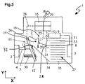
- FIG.1 to FIG.3 described embodiment is not a part of the invention, but the prior art. Nevertheless, this embodiment serves to facilitate the reader's understanding of the invention
- FIG. 1 schematically shows an insight into an open housing 46 of an electrical installation device 1, here a circuit breaker 1.
- a circuit breaker 1 From a first terminal 2 extends a current path via a terminal rail 4 and at a junction 5 welded thereto first conductor piece 6, a strand 7, a movable Contact element 8 and from there via a bobbin of a magnetic release 9 to a second terminal 3.
- the terminals can be designed, for example, as plug-in terminals or as screw terminals as needed.
- a strip 11 of bimetallic welded with its attachment end 12 on the first conductor piece 6 and thus forms a thermal release 13 of the circuit breaker 1.
- the detailed structure of the thermal release 13 is in the DE102009021773A1 described.
- the opposite, free end of the bimetallic strip 11 serves as an actuating end 14 for triggering a unlatching of Verklinkungsstelle a switching mechanism 15 and is connected via a flexible strand 7 with the movable contact element 8.
- the movable contact element 8 is mounted pivotably about a first axis of rotation 16 of a bearing point.
- the electrical service switching device 1 is turned on, wherein the switching mechanism 15 is in a latched (biased) state.
- a shift knob 18 is connected to the switching mechanism 15 such that a user of the electrical installation switching device 1 can visually recognize that the current path is closed.
- the movable contact element 8 has at least one contact piece 20 and, together with a first contact element 21 with likewise at least one fixed contact piece 22, a multiply openable and closable separation point 23 of the current path of the electrical service switching device 1.
- Fig. 2 shows that the electrical installation switching device 1 according to the first embodiment is in the transition from an on state to an off state. Accordingly, there is the movable Contact element 8 between a first end position on the stationary counter contact 21 with a closed current path and a second end position at maximum open position of the movable contact element 8 near the bearing end 32 at the thermal release 13.
- the dynamic release 24 is set to such a threshold value of a short-circuit current that he Transition of the movable contact element 8 from the on state to the off state, the switch latch 15 unlatches and the current path interrupts. In this case, the shift knob 18 is folded by the switch lock 15, so that a user of the electrical installation switching device can visually recognize that the current path is interrupted.
- the term dynamic release 24 is understood to mean the movable contact element 8 and a third line of action 25.
- the dynamic release 24 comprises the switching mechanism 8 and a conductor section 26 with the first contact element 21 and the movable contact element 8.
- the conductor section 26 is electrically interruptible at the separation point 23 by the movable contact element 8.
- the conductor portion 26 is U-shaped at the separation point 23, so that in the event of a short circuit during operation of the service switching device 1, the movable contact element 8 at the separation point 23 due to a resulting magnetic field of the current-carrying conductor portion 26 at the separation point 23 along a path from the first contact element 21st repelled, so lifted and pushed away.
- the movable contact element 8 is operatively connected to a triggering element 37, so that when moving away the movable contact element 8, a triggering of the switching mechanism 15 by unlatching the Verklinkungsstelle can be achieved.
- FIG. 3 shows that the movable contact element 8 is shown in a position in which the current path is completely interrupted by a unlatching of the switching mechanism 15 and the service switching device 1 is turned off.
- the off position when the separation point 23 is open, the free end of the movable contact element 8 is located with the contact piece 20 adjacent to the U-shaped bearing end 32 of the thermal release 13, so that an electric arc for extinction in an arc quenching chamber 27 is commutated.
- the bimetallic strip 11 bends so far with its free end, which is designed as an actuating end 7, due to the overcurrent flowing through it and the current heat generated by it so that it acts on the switching mechanism 15 via a first line of action 28 and ensures there that that a latch is unlatched.
- the realization of the interaction of the bimetallic strip 11 with the switching mechanism 15 can be realized in various ways and for example in the DE102008006863A1 explained in more detail.
- the rear derailleur of the switching mechanism 15 acts on the third line of action 25 on the movable contact element 8 and pivots it in a clockwise direction, so that the movable contact element 8 is lifted from the first contact element 21 and the electrical separation point 23 is opened and kept open by the switch lock 15.
- a reconnection of the switching mechanism 15 can be done via the switch knob 18, which cooperates with the latching mechanism 15 via a fifth line of action 29 and when re-latching the Verklinkungsstelle allowed, as soon as the bimetallic strip 11 has returned to its original position when the overcurrent subsided.
- An adjustment of the thermal release 13 can be carried out via an adjusting screw 30. For more detailed information on this, go to DE102009021773A1 directed.
- the arc guide rail 35 is made with the thermal release 13 and the first conductor piece 6 together with the terminal rail 4 and welded thereto first terminal 2 as a prefabricated unit, which can be used during installation in a rational manner in the service switching device 1.
- no flexible strands are used in the structural unit, but rather solid busbars or conductor strips which are welded or soldered together. Of course, they could also be screwed or connected to one another in a force, shape and / or material fit in any known manner.
- the use of solid components and the elimination of flexible strands promotes easy handling of the module during installation of the service switching device.
- the movable contact element 8 about the first axis of rotation 16 is pivotable.
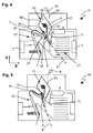
- the switching mechanism 15 itself comprises a contact unit 36 made of insulating material, on which the movable contact element 8 is held and positioned with a torsion spring 37.
- a torsion spring 37 By suitable design of the torsion spring 37 not only the desired contact force with a closed current path, but also the required Maisnachfederung can be achieved. An erosion of the contact pieces 20, 22 and associated loss of material can be compensated so while maintaining a sufficiently sized contact force by tracking the movable contact element 8 by means of the torsion spring 37.
- torsion spring 37 is sized to permit pivoting of the movable contact element 8 about the first axis of rotation 16 during dynamic opening upon the occurrence of high short circuit currents.
- the torsion spring 36 is held on the shorter leg of the contact unit 36, while at the distal end of the longer leg, a bow-shaped portion 38 is arranged.
- the torsion spring 37 is bow-shaped and dimensioned in said section 38, that this section 38 forms the trigger element, which presses in the event of a short circuit during operation of the service switching device directly and in such a way on the trigger mechanism 39, that this triggering mechanism 39 initiates the opening movement of the switching mechanism 15, by unlatching the latch.
- the service switching device of the trigger mechanism 39 is formed by a rotatably mounted on the contact unit 36 of the switching mechanism 15 switching arm 39, the free end is arranged at the closed end current path 14 of the bimetallic strip 11 ThermobimetallstMails.
- the actuating end 14 pushes the switching arm 39 in the direction of the shift knob 18 away, that the Verklinkungsstelle the switching mechanism 15 is unlatched and the current path is interrupted.
- the movable contact element 8, the spring portion 38 and leading to Verklinkungsstelle the switch lock lever 39 functionally the third line of action 25, while the operating end 14 with the lever 39 functionally forms the first line of action 28.
- the switching mechanism 15 is itself pivotally mounted about the second axis of rotation 40 in order to bring the entire switching mechanism 15 by rotation against the closing direction in an open position of the service switching device.
- the axis of rotation 40 may be designed as a parallel guide for a linear movement.
- the second axis of rotation 40 is stationarily mounted in the housing 46 of the service switching device 1.
- the movable contact element has two or more contact pieces instead of a single contact piece, these can be mechanically connected to one another via a supporting contact bridge, wherein the two contact pieces are separated from each other by a recess.
- the switching arm 39 of the triggering mechanism coming from the contact unit 36 may be guided through this recess through to the thermal release 13.
- the proximal end of the spring section 38 presses against the switching arm 39.
- the bow-shaped section 38 of the torsion spring 37 extends in the direction of a first plane 41, which is parallel to a bearing surface 42 of the movable plane Contact element 8 is arranged on the contact unit 36.
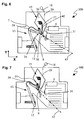
- FIG. 6 and Fig. 7 shown third embodiment of an electrical installation switching device 100 differs only in the design of the bow-shaped portion 38 of the torsion spring 37 from the basis 4 and FIG. 5 Specifically, the difference lies in the fact that the bow-shaped portion 38 extends in the third embodiment 100 in the direction of a second plane 42, which second plane 43 transversely, that is seen in the XY plane obliquely to the support surface 42nd of the movable contact element 8 extends to the contact unit 36.
- This is in contrast to the second embodiment 10 according to Fig. 4 a translation of the comparatively small pivoting movement of the bow-shaped portion 38 relative to the movement of the movable contact element 8 achievable to enlarge the path portion for triggering the unlatching of the Verklinkungsstelle.
- the movable contact element instead of a single contact piece 20 has two or more contact pieces, these can be mechanically connected to each other again via a supporting contact bridge, wherein the two contact pieces are separated by a recess. If necessary, the switching arm 39 of the release mechanism of the contact unit 36 come to be guided through this recess through the thermal release 13. In this case, when viewed in the Y direction, the proximal end of the spring section 38 presses against the switching arm 39.
- the bow-shaped section 38 of the torsion spring 37 extends in the direction of the first plane 41, which first plane 41 parallel to the bearing surface 40 of the movable contact element 8 is arranged on the contact unit 36.
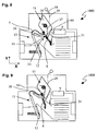
- the fourth embodiment of an electrical installation switching device 1000 shown differs from the second embodiment 10 and the third embodiment 100 in that the movable contact element 8 has a recess 44 through which the triggering mechanism 39 is led out.
- the fourth embodiment 1000 does not form a spring portion of the torsion spring 37, the trigger element, but an inner contour portion 45 of the movable contact element 8 at the recess 44.
- lower edge 45 of the recess forms the actual trigger element of the dynamic Trigger 24.
- the edge 45 is executed acute-angled and only slightly deburred, preferably rounded. Referring to the schematic representation in FIG Fig.
Description
Die Erfindung betrifft einen dynamischen Auslöser für ein elektrisches Installations-schaltgerät, insbesondere einen Leitungsschutzschalter, sowie ein elektrisches Schaltgerät mit einem vorgenannten dynamischen Auslöser.The invention relates to a dynamic release for an electrical installation switching device, in particular a circuit breaker, and an electrical switching device with an aforementioned dynamic release.
Auf dem Markt und in der Patentliteratur sind etliche elektrische Installationsschaltgeräte bekannt, beispielsweise in Form von Sicherungsautomaten oder Leitungsschutzschalter. Im Fall von Leitungsschutzschaltern erfolgt eine Absicherung der Installationen gegen elektrische Fehler in der Regel über einen thermischen Auslöser und einen elektromagnetischen Auslöser, welche beim Auftreten eines elektrischen Fehlers im Betrieb des Leitungsschutzschalters derart auf ein Schaltschloss des Leitungsschutzschalters einwirken, dass dieser entklinkt (auslöst) und eine selbsttätige Unterbrechung des Strompfades führt. Jener Strompfad erstreckt sich über einen typischerweise durch den Leitungsschutzschalter geführten Leiterabschnitt und ist an einer Trennstelle vom Schaltschloss elektrisch unterbrechbar. Ist eine sogenannte Verklinkungsstelle eines Schaltschlosses entklinkt, wird meist ein bewegliches Kontaktelement an der Trennstelle entlang einer Bahn von einem stationären Kontaktelement weggeschwenkt und damit der Strompfad bis zum gezielten Wiedereinschalten des Leitungsschutzschalters sicher und zuverlässig unterbrochen.Several electrical service switching devices are known on the market and in the patent literature, for example in the form of circuit breakers or circuit breakers. In the case of miniature circuit breakers, the installations are usually protected against electrical faults by means of a thermal release and an electromagnetic release, which in the event of an electrical fault during operation of the circuit breaker act on a circuit breaker of the circuit breaker such that it unlatches (triggers) and a automatic interruption of the current path leads. That current path extends over a conductor section, which is typically routed through the circuit breaker, and is electrically interruptible at a disconnection point by the switching mechanism. Is a so-called Verklinkungsstelle a switching lock unlatched, usually a movable contact element at the separation point along a path of a stationary contact element is pivoted away and thus the current path safely and reliably interrupted until the targeted restart of the circuit breaker.
Eine Auslösung des Schaltschlosses bei elektrischer Überlast mit dem thermischen Auslöser erfolgt dann, wenn der vorgegebene Nennwert des durch den Leitungsschutzschalterfliessenden Stromes längere Zeit erheblich überschritten wird. Die Zeit bis zur Auslösung hängt von der Stärke des Überstroms ab. Wenn der Strom im Hauptstrompfad längere Zeit über dem Nennstrom bleibt, spricht man von einem Überstrom.A triggering of the switching mechanism in case of electrical overload with the thermal release takes place when the predetermined nominal value of the current flowing through the circuit breaker current is exceeded considerably longer time. The time to trip depends on the magnitude of the overcurrent. If the current in the main current path remains above the rated current for a longer time, this is called an overcurrent.
Bei hohem Überstrom ist sie meist kürzer als bei geringer Überschreitung des Nennstromes. Zur Auslösung wird ein Bimetall verwendet, das sich bei Erwärmung durch den durchfliessenden Strom verbiegt und den Abschaltmechanismus auslöst. Die Verwendung eines thermischen Auslösers, umfassend einen Streifen aus Thermobimetall oder aus einer Formgedächtnislegierung ist bekannt. Jener thermische Auslöser wirkt bei einer Auslösung auf eine Verklinkungsstelle des Schaltschlosses, das mit dem beweglichen Kontaktelement gekoppelt ist, zu deren Entklinkung ein.At high overcurrent, it is usually shorter than at low overshoot of the rated current. To trigger a bimetal is used, which bends when heated by the flowing stream and triggers the shutdown mechanism. The use of a thermal release comprising a strip of bimetallic strip or of a shape memory alloy is known. That thermal release acts in a release to a Verklinkungsstelle the switching mechanism, which is coupled to the movable contact element, to their unlatching.
Der elektromagnetische Auslöser öffnet etwa bei Auftreten eines Kurzschlussstromes das bewegliche Kontaktelement unmittelbar durch Aufschlagen, typischerweise mit hilfe eines Schlagankers. Gleichzeitig betätigt der elektromagnetische Auslöser auch das Schaltschloss, damit das Schaltgerät bleibend geöffnet ist.The electromagnetic release opens about when a short-circuit current occurs, the movable contact element directly by impact, typically by means of a percussion anchor. At the same time, the electromagnetic release also actuates the switch lock, so that the switching device is permanently open.
Ein Auslösen (Entklinken) des Schaltschlosses und damit der Unterbruch des Strompfades mittels dem elektromagnetischen Auslöser innerhalb weniger Millisekunden erfolgt dann, wenn in einer Anlage ein Kurzschluss auftritt. In diesem Fehlerfall erfolgt die Abschaltung durch einen vom Strom durchflossenen Elektromagneten, welcher etwa über einen Schlaganker derart auf das Schaltschloss einwirkt, dass dieses entklinkt und den Strompfad unterbricht.A tripping (unlatching) of the switching mechanism and thus the interruption of the current path by means of the electromagnetic release within a few milliseconds takes place when a short circuit occurs in a system. In this case of error, the shutdown is carried out by a current flowing through the electromagnet, which acts on such a way about a shock anchor on the switch lock, that this unlatches and interrupts the current path.
Weiter sind Leitungsschutzschalter bekannt, bei welchen das Magnetfeld eines durchflossenen Leiters im Falle von grossen Strömen (wie sie beispielsweise bei Überlast auftreten) gezielt zum Auslösen der Verklinkungsstelle des Schaltschlosses einzusetzen. So schlägt beispielsweise die
Aus der
Auch bei elektrischen Installationsschaltgeräten wie etwa Leitungsschutzschaltern bilden die räumlichen Abmessungen ein wichtiges Anwendungskriterium. Besonders dann, wenn eine bestehende Elektroinstallation für höhere Leistungen nachgerüstet werden muss, etwa bei einem Retrofit, ist der für einen Einbau eines solchen Gerätes zur Verfügung stehende Platz vorgegeben und ohnehin bereits knapp bemessen. Entsprechend ist die Kompaktheit des Installationsschaltgerätes entscheidend für einen Einsatz eines Ersatz-Installations-schaltgerätes.Even with electrical installation switching devices such as circuit breakers, the spatial dimensions form an important application criterion. Especially when an existing electrical installation for higher performance must be retrofitted, such as a retrofit, the space available for installation of such a device space is given and already already tight. Accordingly, the compactness of the service switching device is crucial for the use of a replacement installation switching device.
Der vorliegenden Erfindung liegt im Lichte des Standes der Technik daher die Aufgabe zugrunde, einen Auslöser für ein elektrisches Installationsschaltgerät, insbesondere Leitungsschutzschalter, Motorschutzschalter oder dergleichen vorzulegen, bei welchem das Magnetfeld eines durchflossenen Leiterabschnitts zum Entklinken eines Schaltschlosses nutzbar ist, ohne dabei die Kompaktheit des elektrischen Installationsschaltgerät negativ zu beeinflussen.The present invention is therefore in the light of the prior art, the object of a trigger for an electrical service switching device, in particular circuit breaker, Motor protection switch or the like to submit, in which the magnetic field of a conductor portion through which is passed for unlatching a switching mechanism, without negatively affecting the compactness of the electrical installation switching device.
Die der Erfindung zugrundeliegende Aufgabe wird bezüglich des Auslösers erfindungsgemäss gelöst durch ein verbessertes Installationsschaltgerätes mit den kennzeichnenden Merkmalen des Anspruchs 1 oder des Anspruchs 7.The object underlying the invention is achieved according to the invention with respect to the trigger by an improved service switching device with the characterizing features of
Vereinfacht dargestellt wir die oben genannte Aufgabe dadurch gelöst, dass der Leiterverlauf des dynamischen Auslösers so gestaltet ist, dass eine Schwenkbewegung des bewegliche Kontakt bei einer Trennstelle beim dynamischen Abheben von einem Gegenkontakt infolge der resultierenden Magnetfeldkräfte gezielt zum Entklinken des Schaltschlosses eingesetzt wird.Simplified, we presented the above object achieved in that the conductor profile of the dynamic release is designed so that a pivoting movement of the movable contact at a separation point during dynamic lifting of a mating contact due to the resulting magnetic forces targeted for unlatching the switching mechanism is used.
In einer Basisausführungsform weist der Auslöser für ein elektrisches Installationsschaltgerät, insbesondere einen Leitungsschutzschalter, einen Motorschutzschalter oder dergleichen, ein Schaltschloss und einen Leiterabschnitt mit einem ersten Kontaktelement und einem beweglichen Kontaktelement auf. Dabei ist der Leiterabschnitt an einer Trennstelle durch das bewegliche Kontaktelement elektrisch unterbrechbar. Der Leiterabschnitt bei der Trennstelle derart, dass bei einem Kurzschluss im Betrieb des Installationsschaltgeräts das bewegliche Kontaktelement an der Trennstelle aufgrund eines resultierenden Magnetfeldes des stromdurchflossenen Leiterabschnitts bei der Trennstelle entlang einer Bahn vom ersten Kontaktelement abstossbar und wegbewegbar ist. Je nach Ausgestaltung kann der Leiterverlauf bei der Trennstelle beispielsweise U-förmig oder V-förmig geformt sein. Der Auslöser weist ein Auslöseelement auf, das mit dem beweglichen Kontaktelement derart wirkverbunden ist, dass beim Wegbewegen des beweglichen Kontaktelements ein Entklinken der Verklinkungsstelle des Schaltschlosses erzielbar ist.In a basic embodiment, the trigger for an electrical installation switching device, in particular a circuit breaker, a motor protection switch or the like, a switching mechanism and a ladder section having a first contact element and a movable contact element. In this case, the conductor section is electrically interruptible at a separation point by the movable contact element. The conductor section at the separation point such that in the event of a short circuit during operation of the service switching device, the movable contact element at the separation point due to a resulting magnetic field of the current-carrying conductor portion at the separation point along a path from the first contact element is repeleable and wegbewegbar. Depending on the configuration of the conductor profile at the separation point, for example, U-shaped or V-shaped. The trigger has a triggering element, which is operatively connected to the movable contact element such that when moving away the movable contact element, a unlatching of the latching point of the switching mechanism can be achieved.
Ein erster Vorteil eines solchen Aufbaus des dynamischen Auslösers liegt darin, dass das in den meisten Fällen ohnehin bereits vorhandene bewegliche Kontaktelement nun ebenfalls zum Entklinken des Schaltschlosses einsetzbar ist. Dies erlaubt es, auf separate Hebelsysteme und dergleichen mit eigenen beweglichen Elementen weitestgehend zu verzichten, wodurch der Platzbedarf für das elektrische Installationsschaltgerät nicht oder höchstens geringfügig grösser ist, als bei bekannten elektrischen Installationsschaltgeräten ohne den dynamischen Auslöser.A first advantage of such a construction of the dynamic release is that the already existing in most cases movable contact element is now also used for unlatching the switch lock. This makes it possible to dispense with separate lever systems and the like with their own moving elements as far as possible, whereby the space required for the electrical service switching device is not or at most slightly larger than in known electrical service switching devices without the dynamic release.
Ein weiterer Vorteil liegt darin, dass durch die Mehrfachnutzung des in den meisten Fällen ohnehin bereits vorhandene bewegliche Kontaktelements die Montage des elektrischen Installationsschaltgerätes trotz einer Zusatzfunktion in Form des dynamischen Auslösens im Vergleich zu bekannten elektrischen Installationsschaltgeräten ohne den dynamischen Auslöser nicht oder höchstens geringfügig vergrössert wird.Another advantage is that due to the multiple use of the already existing in most cases already movable contact element assembly of the electrical service switching device despite an additional function in the form of dynamic release compared to known electrical service switching devices without the dynamic release is not or at most slightly increased.
Ein weiterer Vorteil liegt darin, dass durch die Mehrfachnutzung des in den meisten Fällen ohnehin bereits vorhandene bewegliche Kontaktelements die Teileanzahl und Komplexität des elektrischen Installationsschaltgerätes trotz der Zusatzfunktion in Form des dynamischen Auslösens nicht oder höchstens geringfügig vergrössert wird.Another advantage is that the number of parts and complexity of the electrical service switching device despite the additional function in the form of dynamic triggering is not or at most increased slightly by the multiple use of in most cases already existing movable contact element.
Je nach Ausführungsform des Installationsschaltgerätes bzw. des dynamischen Auslösers kann das erste Kontaktelement ein stationärer Kontakt sein.Depending on the embodiment of the service switching device or the dynamic release, the first contact element may be a stationary contact.
In einer Basisausführungsform weist das elektrische Installationschaltgerät, insbesondere ein Leitungsschutzschalter, ein Motorschutzschalter oder dergleichen, ein Schaltschloss und einen Leiterabschnitt mit einem ersten Kontaktelement und einem beweglichen Kontaktelement auf. Dabei ist der Leiterabschnitt an einer Trennstelle durch das bewegliche Kontaktelement elektrisch unterbrechbar. Der Leiterabschnitt bei der Trennstelle derart, dass bei einem Kurzschluss im Betrieb des Installationsschaltgeräts das bewegliche Kontaktelement an der Trennstelle aufgrund eines resultierenden Magnetfeldes des stromdurchflossenen Leiterabschnitts bei der Trennstelle entlang einer Bahn vom ersten Kontaktelement abstossbar und wegbewegbar ist. Je nach Ausgestaltung kann der Leiterverlauf bei der Trennstelle beispielsweise U-förmig oder V-förmig geformt sein. Das elektrische Installationschaltgerät weist ein Auslöseelement auf, das mit dem beweglichen Kontaktelement derart wirkverbunden ist, dass beim Wegbewegen des beweglichen Kontaktelements ein Entklinken der Verklinkungsstelle des Schaltschlosses erzielbar ist.In a basic embodiment, the electrical installation switching device, in particular a circuit breaker, a motor protection switch or the like, a switching mechanism and a ladder section with a first contact element and a movable contact element. In this case, the conductor section is electrically interruptible at a separation point by the movable contact element. The conductor section at the separation point such that in the event of a short circuit during operation of the service switching device, the movable contact element at the separation point due to a resulting magnetic field of the current-carrying conductor portion at the separation point along a path from the first contact element is repeleable and wegbewegbar. Depending on the configuration of the conductor profile at the separation point, for example, U-shaped or V-shaped. The electrical installation switching device has a triggering element, which is operatively connected to the movable contact element such that when the movable contact element is moved away, a unlatching of the latching point of the switching mechanism can be achieved.
Das erfindungsgemässe Installationschaltgerät weist zudem eine thermische Auslöseeinrichtung, umfassend ein durch den Strom auslenkbares Bimetallelement oder einer Vorrichtung mit einer Formgedächtnislegierung auf, wobei das Schaltschloss von der thermische Auslöseeinrichtung über eine Wirklinie bildenden Auslösemechanismus auslösbar, das heisst entklinkbar ist. Unter den Begriff "Wirklinie" wird dabei eine Vorrichtung, insbesondere eine mechanische Vorrichtung verstanden, welche zum Einwirken auf das Schaltschloss dient oder vom Schaltschloss her auf ein Element, etwa in Form eines Kipphebels einwirkt.The inventive installation switching device also has a thermal trip device comprising a deflectable by the current bimetallic element or a device with a shape memory alloy, wherein the switch lock of the thermal release device via a line of action forming release mechanism triggered, that is unlatched. The term "line of action" is understood to mean a device, in particular a mechanical device, which acts on the switching mechanism or acts on the switching mechanism on an element, for example in the form of a rocker arm.
Zur Gewährleistung, dass das bewegliche Kontaktelement in geschlossenem Zustand mit einem gewissen Kontaktdruck gegen das erste Kontaktelement (den Gegenkontakt) gedrückt werden kann, sind mechanisch zuverlässige Installationschaltgeräte dadurch erreichbar, dass das bewegliche Kontaktelement mit einer Feder an einer Kontakteinheit des Schaltschlosses derart gehalten und positioniert ist. Ein Abschnitt dieser Feder bildet das Auslöseelement und ist dazu in jenem Abschnitt (nachfolgend auch Federabschnitt genannt) so ausgeformt, dass dieser Abschnitt bei einem Kurzschluss im Betrieb des Installationsschaltgeräts derart auf den Auslösemechanismus drückt, dass dieser Auslösemechanismus die Entklinkung der Verklinkungsstelle und damit eine Ausschaltbewegung des Schaltschlosses initiiert.To ensure that the movable contact element in the closed state with a certain contact pressure against the first contact element (the mating contact) can be pressed, mechanically reliable placements are achievable in that the movable contact element is held and positioned with a spring on a contact unit of the switch latch , A portion of this spring forms the triggering element and is in addition to that section (hereinafter also referred to as a spring section) in such a way that this section presses in a short circuit during operation of the service switching device on the trigger mechanism such that this triggering mechanism initiates the unlatching of Verklinkungsstelle and thus a turn-off movement of the switching mechanism.
Ein weiterer Vorteil der Verwendung einer Feder besteht darin, dass mit ihr das bewegliche Kontaktelement mit einer Feder an einer bei Bedarf beweglich im Leistungsschalter gelagerten Kontakteinheit des Schaltschlosses derart festhaltbar und positionierbar ist, dass das bewegliche Kontaktelement um einen Drehpunkt an der Kontakteinheit herum vom stationären Kontakt bzw. -Element wegbewegbar ist.Another advantage of the use of a spring is that with it the movable contact element with a spring on a movably mounted in the circuit breaker contact unit of the switch latch is fixed and positioned so that the movable contact element about a pivot point on the contact unit from the stationary contact or element is movable away.
Die Verwendung eines Kontakteinheit des Schaltschlosses kann vorteilhaft sein, um eine erste Drehachse des beweglichen Kontaktelements relativ zur Kontakteinheit zu begründen, um ein dynamisches Abheben des beweglichen Kontaktelements vom Gegenkontakt zuzulassen, ohne dass das Schaltschloss gleich entklinkt wird. Dadurch ist eine gewisse Toleranz des Installationsschaltgerät gegenüber Strom- oder Spannungsschwankungen aufgrund von unkritischen Fehlern und dergleichen im abzusichernden Stromnetz zu ermöglichen.The use of a contact unit of the switch lock may be advantageous to establish a first axis of rotation of the movable contact element relative to the contact unit to allow a dynamic lifting of the movable contact element from the mating contact, without the latch is unlatched immediately. This allows a certain tolerance of the service switching device against current or voltage fluctuations due to uncritical errors and the like to be secured in the power grid.
Je nach Aufbau des Schaltschlosses sind Ausführungsformen realisierbar, bei welchen die Feder eine Torsionsfeder ist und der Abschnitt der Feder bügelförmig ist. Bei Bedarf kann die Feder eine Einfachtorsionsfeder oder eine Mehrfachtorsionsfeder, etwa eine Doppeltorsionsfeder sein.Depending on the structure of the switch lock embodiments are feasible, in which the spring is a torsion spring and the portion of the spring is bow-shaped. If necessary, the spring may be a single torsion spring or a multiple torsion spring, such as a double torsion spring.
Ein besonders platzsparender dynamischer Auslöser und damit ein besonders kompaktes Installationsschaltgerät ist dann erzielbar, wenn sich der bügelförmige Abschnitt in Richtung einer ersten Ebene erstreckt, welche erste Ebene parallel zu einer Auflagefläche des beweglichen Kontaktelements an der Kontakteinheit (36) angeordnet ist.A particularly space-saving dynamic release and thus a particularly compact installation switching device can be achieved if the bow-shaped portion extends in the direction of a first plane, which first plane is arranged parallel to a bearing surface of the movable contact element on the contact unit (36).
Die bezüglich des dynamischen Auslösers genannten Vorteile erstrecken sich entsprechend auf das mit ihm ausgerüstete elektrische Installationschaltgerät.The advantages referred to the dynamic release extend correspondingly to the electrical installation switching device equipped with it.
Ein weiterer Vorteil liegt darin, dass sich ein bestehendes elektrische Installationschaltgerät durch einen Austausch des vorhandenen beweglichen Kontaktelements zu einem Installationschaltgerät mit der Zusatzfunktion des dynamischen Öffnens nachrüsten lässt, sofern ein bestehender Auslösemechanismus zum Entklinken des Schaltschlosses wiederverwendbar ist.A further advantage is that an existing electrical installation switching device can be retrofitted by replacing the existing movable contact element to a service switching device with the additional function of dynamic opening, if an existing release mechanism for unlatching the switching mechanism is reusable.
Ein weiterer Vorteil liegt darin, dass der dynamische Auslöser bei Bedarf eine alternative oder eine zusätzliche Funktionalität zum elektromagnetischen Auslöser bilden kann. Eine ergänzende, zusätzliche Funktionalität ist etwa dann erzielbar, wenn die Auslösecharakteristiken des dynamischen Auslösers und des elektromagnetischen Auslösers auf unterschiedliche Schwellwerte festgelegt sind, um einem Benutzer des elektrische Installationschaltgerätes bei zwei unterschiedlichen Kurzschlussströmen unterschiedliche Schutzabschaltungen zu ermöglichen.Another advantage is that the dynamic release can provide an alternative or additional functionality to the electromagnetic release as needed. Supplementary additional functionality can be achieved, for example, if the triggering characteristics of the dynamic release and the electromagnetic release are set to different threshold values in order to assist a user of the electrical installation switching device two different short-circuit currents to allow different protection shutdowns.
Es ist bei Bedarf auch möglich, den Schwellwert des dynamischen Auslösers so anzupassen, dass der dynamische Auslöser bei gleichen Kurzschlusströmen wie der elektromagnetischen Auslösers eine Entklinkung des Schaltschlosses hervorruft. In diesem Fall kann der dynamische Auslöser eine Redundanz zum elektromagnetischen Auslöser und umgekehrt schaffen.If necessary, it is also possible to adjust the threshold value of the dynamic release such that the dynamic release causes the latching mechanism to unlatch at the same short-circuit currents as the electromagnetic release. In this case, the dynamic release can provide redundancy to the electromagnetic release and vice versa.
Ein weiterer Vorteil des dynamischen Auslösens der Entklinkung des Schaltschlosses liegt darin, dass sie zeitlich schneller ist, als die Entklinkung mit dem elektromagnetischen Auslöser, welcher ansprechträger als der dynamischen Auslöser ist.Another benefit of dynamically triggering the unlatching of the latch is that it is faster in time than unlatching with the electromagnetic trip that is the trigger of the dynamic release.
Eine mechanisch besonders einfache Ausführungsform eines Installationschaltgerätes ist dann erzielbar, wenn der Auslösemechanismus einen Schaltarm aufweist und das Schaltschloss direkt vom Auslöseelement über den Schaltarm entklinkbar ist. Je nach Ausführungsform kann der Auslösemechanismus selber aus lediglich einem Schaltarm bestehen. Besonders kompakte und mechanisch dennoch einfache Ausführungsformen eines Installationschaltgerätes sind realisierbar, wenn der Schaltarm ohnehin bereits vorhanden ist, etwa im Zusammenhang mit einem elektromagnetischen Auslöser oder einem thermischen Auslöser.A mechanically particularly simple embodiment of an installation switching device can be achieved if the triggering mechanism has a switching arm and the switching mechanism can be unlatched directly from the triggering element via the switching arm. Depending on the embodiment, the trigger mechanism itself may consist of only one switching arm. Particularly compact and yet mechanically simple embodiments of an installation switching device can be realized if the switching arm is already present, for example in connection with an electromagnetic release or a thermal release.
Besonders geringe Veränderungen an bestehenden Installationschaltgeräten sind trotz der Zusatzfunktion des dynamischen Auslösens erzielbar, wenn das Auslöseelement ein Konturbereich des beweglichen Kontaktelements ist. Dabei ist der Konturbereich so ausgeformt und relativ zum Schaltarm so angeordnet, dass dieser Konturbereich bei einem Kurzschluss im Betrieb des Installationsschaltgeräts derart auf den Schaltarm drückt, dass der Schaltarm die Ausschaltbewegung des Schaltschlosses initiiert. Je nach Ausgestaltung des dynamischen Auslösers bzw. des Installationschaltgerätes kann dieser Konturbereich Bestandteil einer Aussenkontur oder Bestandteil einer Innenkontur des beweglichen Kontaktelements sein. Als stellvertretendes Beispiel für eine Innenkontur sei hier eine Kante einer Durchdringung in einem sonst streifenförmigen beweglichen Kontaktelement genannt.Particularly small changes to existing installation switching devices can be achieved despite the additional function of the dynamic release, when the trigger element is a contour region of the movable contact element. In this case, the contour region is formed and arranged relative to the switching arm so that this contour region presses in a short circuit during operation of the service switching device on the switching arm such that the switching arm initiates the switch-off movement of the switching mechanism. Depending on the configuration of the dynamic release or the installation switching device, this contour region may be part of an outer contour or part of an inner contour of the movable contact element. As a representative example of an inner contour is here called an edge of a penetration in an otherwise strip-shaped movable contact element.
Wenn die Verklinkungsstelle im Betrieb des Installationsschaltgerätes bei einem Kurzschluss bereits dann entklinkt werden soll, wenn das bewegliche Kontaktelement noch nicht die gesamten maximal mögliche Bewegung entlang einer Bahn vom ersten Kontaktelement her zurückgelegt hat, so ist dies beispielsweise über eine Übersetzung der Bewegung des Auslöseelements relativ zur Bewegung des beweglichen Kontaktelements erreichbar. In einer Ausführungsform des dynamischen Auslösers bzw. des Installationsschaltgerätes ist diese Übersetzung dadurch erreichbar, dass sich der bügelförmige Abschnitt der Feder in Richtung einer zweiten Ebene erstreckt, wobei diese zweite Ebene quer zu einer Auflagefläche des beweglichen Kontaktelements an der Kontakteinheit angeordnet ist. Unter dem Begriff "quer" werden nicht nur sich orthogonal zur Auflagefläche erstreckende Ausrichtungen verstanden, sondern auch Ausrichtungen, bei welchen die zweite Ebene schräg zu einer Auflagefläche des beweglichen Kontaktelements an der Kontakteinheit angeordnet ist.If the latching point during operation of the service switching device is already unlatched in a short circuit when the movable contact element has not covered the entire maximum possible movement along a path from the first contact element ago, this is for example via a translation of the movement of the trigger element relative to Movement of the movable contact element achievable. In one embodiment of the dynamic release or the installation switching device, this translation is achieved in that the bow-shaped portion of the spring extends in the direction of a second plane, said second plane is arranged transversely to a bearing surface of the movable contact element on the contact unit. Under the term "cross" be not only understood orthogonal to the support surface extending orientations, but also orientations in which the second plane is arranged obliquely to a bearing surface of the movable contact element on the contact unit.
Falls es die Gestaltung des beweglichen Kontaktelements erlaubt und der Aufbau des Installationsschaltgerätes erfordert, kann das bewegliche Kontaktelement in diesen Fällen eine Aussparung aufweisen, durch welche der Auslösemechanismus herausgeführt ist. Wie oben bereits erwähnt, kann dabei eine Innenkontur, etwa eine Kante der Aussparung sein, welche bei einem Kurzschluss im Betrieb des Installationsschaltgeräts derart auf den Schaltarm drückt, dass der Schaltarm die Ausschaltbewegung des Schaltschlosses initiiert und entklinkt.If it allows the design of the movable contact element and requires the structure of the service switching device, the movable contact element in these cases may have a recess through which the trigger mechanism is led out. As already mentioned above, an inner contour, for example an edge of the recess, which in the event of a short circuit during operation of the service switching device presses on the switching arm such that the switching arm initiates and unlatches the opening movement of the switching mechanism.
Nachfolgend werden mehrere Ausführungsformen der Erfindung anhand der Zeichnung detailliert erläutert. Hierbei zeigt rein schematisch
- FIG. 1
- eine erste Ausführungsform eines elektrischen Installationsschaltgeräts in eingeschaltetem Zustand, bei welchem ein Schaltschloss verklinkt ist;
- FIG. 2
- das elektrische Installationsschaltgeräts von
Fig. 1 beim Übergang vom eingeschaltetem Zustand in einen ausgeschaltetem Zustand, wobei das Schaltschloss entklinkt und der Strompfad unterbrochen sind; - FIG. 3
- das elektrische Installationsschaltgeräts von
Fig. 1 und 2 in ausgeschaltetem Zustand, wobei das Schaltschloss entklinkt und der Strompfad unterbrochen sind; - FIG. 4
- eine zweite Ausführungsform eines elektrischen Installationsschaltgeräts in eingeschaltetem Zustand, bei welchem ein Schaltschloss verklinkt ist;
- FIG. 5
- das elektrische Installationsschaltgeräts von
Fig. 4 beim Übergang vom eingeschaltetem Zustand in einen ausgeschaltetem Zustand, wobei das Schaltschloss entklinkt und der Strompfad unterbrochen sind; - FIG. 6
- eine dritte Ausführungsform eines elektrischen Installationsschaltgeräts in eingeschaltetem Zustand, bei welchem ein Schaltschloss verklinkt ist;
- FIG. 7
- das elektrische Installationsschaltgeräts von
Fig. 6 beim Übergang vom eingeschaltetem Zustand in einen ausgeschaltetem Zustand, wobei das Schaltschloss entklinkt und der Strompfad unterbrochen sind; - FIG. 8
- eine vierte Ausführungsform eines elektrischen Installationsschaltgeräts in eingeschaltetem Zustand, bei welchem ein Schaltschloss verklinkt ist; und
- FIG. 9
- das elektrische Installationsschaltgeräts von
Fig. 8 beim Übergang vom eingeschaltetem Zustand in einen ausgeschaltetem Zustand, wobei das Schaltschloss entklinkt und der Strompfad unterbrochen sind.
- FIG. 1
- a first embodiment of an electrical installation switching device in the on state, in which a switching lock is latched;
- FIG. 2
- the electrical installation switching device of
Fig. 1 in the transition from the switched state to a switched-off state, wherein the switching lock is unlatched and the current path is interrupted; - FIG. 3
- the electrical installation switching device of
Fig. 1 and 2 in the off state, with the switch lock unlatched and the current path interrupted; - FIG. 4
- a second embodiment of an electrical installation switching device in the on state, in which a switching lock is latched;
- FIG. 5
- the electrical installation switching device of
Fig. 4 in the transition from the switched state to a switched-off state, wherein the switching lock is unlatched and the current path is interrupted; - FIG. 6
- a third embodiment of an electrical installation switching device in the on state, in which a switching lock is latched;
- FIG. 7
- the electrical installation switching device of
Fig. 6 in the transition from the switched state to a switched-off state, wherein the switching lock is unlatched and the current path is interrupted; - FIG. 8th
- a fourth embodiment of an electrical installation switching device in the on state, in which a switching lock is latched; and
- FIG. 9
- the electrical installation switching device of
Fig. 8 at the transition from the switched state to a switched-off state, wherein the switch lock is unlatched and the current path is interrupted.
In den Figuren sind gleiche oder gleichwirkende Bauteile oder Elemente mit den gleichen oder zumindest ähnlichen Bezugsziffern versehen.In the figures, identical or equivalent components or elements are provided with the same or at least similar reference numerals.
Bei der anhand von
Das gegenüberliegende, freie Ende des Thermobimetallstreifens 11 dient als Betätigungsende 14 zur Auslösung einer Entklinkung der Verklinkungsstelle eines Schaltschlosses 15 und ist mit über eine biegsame Litze 7 mit dem beweglichen Kontaktelement 8 verbunden. Das bewegliche Kontaktelement 8 ist um eine erste Drehachse 16 einer Lagerstelle verschwenkbar gelagert.The opposite, free end of the
Im in
Das bewegliche Kontaktelement 8 weist mindestens ein Kontaktstück 20 auf und bildet zusammen mit einem ersten Kontaktelement 21 mit ebenfalls mindestens einem festen Kontaktstück 22 eine mehrfach öffenbare und schliessbare Trennstelle 23 des Strompfades des elektrischen Installationsschaltgeräts 1.The
Aus der Zusammenschau mit
Der dynamische Auslöser 24 umfasst das Schaltschloss 8 und einen Leiterabschnitt 26 mit dem ersten Kontaktelement 21 und dem beweglichen Kontaktelement 8. Der Leiterabschnitt 26 ist an der Trennstelle 23 durch das bewegliche Kontaktelement 8 elektrisch unterbrechbar. Der Leiterabschnitt 26 ist bei der Trennstelle 23 U-förmig ausgebildet, so dass bei einem Kurzschluss im Betrieb des Installationsschaltgeräts 1 das bewegliche Kontaktelement 8 an der Trennstelle 23 aufgrund eines resultierenden Magnetfeldes des stromdurchflossenen Leiterabschnitts 26 bei der Trennstelle 23 entlang einer Bahn vom ersten Kontaktelement 21 abgestossen, also abgehoben und weggeschoben wird. Das bewegliche Kontaktelement 8 ist mit einem Auslöseelement 37 wirkverbunden, so dass beim Wegbewegen des beweglichen Kontaktelements 8 ein Auslösen des Schaltschlosses 15 mittels Entklinken der Verklinkungsstelle erzielbar ist.The
Aus der Zusammenschau mit
Der Thermobimetallstreifen 11 biegt sich mit seinem freien Ende, das als Betätigungsende 7 ausgebildet ist, aufgrund des durch ihn hindurchfliessenden Überstroms und der durch ihn erzeugten Stromwärme so weit aus, dass er über eine erste Wirklinie 28 auf das Schaltschloss 15 einwirkt und dort dafür sorgt, dass eine Verklinkungsstelle entklinkt wird. Die Realisierung der Wechselwirkung des Thermobimetallstreifens 11 mit dem Schaltschloss 15 ist auf verschiedene Weisen realisierbar und beispielsweise in der
Ein Wiedereinschalten des Schaltschlosses 15 kann über den Schaltknauf 18 erfolgen, der über eine fünfte Wirklinie 29 mit dem Schaltschloss 15 zusammenwirkt und bei Betätigung ein Wiederverklinken der Verklinkungsstelle erlaubt, sobald sich das Thermobimetall 11 beim Abklingen des Überstroms sich wieder in seine Ausgangsposition zurückbegeben hat. Eine Justierung des thermischen Auslösers 13 ist über eine Einstellschraube 30 durchführbar. Für detailliertere Informationen dazu wird auf die
Wenn ein Kurzschlussstrom/Überstrom durch den Strompfad fliesst, also ein in sehr kurzer Zeit auf ein Mehrfaches des Nennstroms ansteigender Strom, so spricht der Magnetauslöser 9 an. Dieser schlägt dann über eine vierte Wirklinie 31 direkt und schnell das bewegliche Kontaktelement 8 auf, gleichzeitig wirkt er über eine zweite Wirklinie 47 auch auf das Schaltschloss 15 zur Entklinkung von dessen Verklinkungsstelle und zur dauerhaften Offenhaltung der Trennstelle 23 bis zum Wiedereinschalten ein.If a short-circuit current / overcurrent flows through the current path, ie a current that increases to a multiple of the rated current in a very short time, the
Bei einem schnellen Öffnen der Trennstelle 23 entsteht zwischen den sich voneinander wegbewegenden Kontaktelementen 8,21 ein Schaltlichtbogen. Dieser kommutiert nach kurzer Zeit auf eine Festkontaktleitschiene 33 und über einen ersten Leitschenkel 34 auf eine Lichtbogenleitschiene 35 und wird in die Lichtbogenlöschkammer 27 geführt, wo er erlischt. Solange der Lichtbogen noch nicht verloschen ist, trägt dieser den Kurzschlussstrom. Die Lichtbogenleitschiene 35 und die Lichtbogenlöschkammer 27 sind ortsfest am Gehäuse 46 des Installationsschaltgeräts 1 gelagert und gehalten.In a rapid opening of the
Die Lichtbogenleitschiene 35 ist mit dem thermischen Auslöser 13 und dem ersten Leiterstück 6 samt Klemmenschiene 4 und daran angeschweisster erster Anschlussklemme 2 als vorgefertigte Baueinheit hergestellt, welche bei der Montage in rationeller Weise in das Installationsschaltgerät 1 hineineingesetzt werden kann. Es werden bei der Baueinheit erfindungsgemäss keine flexiblen Litzen verwendet, sondern durchweg feste Stromschienen oder Leiterstreifen, die miteinander verschweisst oder verlötet sind. Sie könnten natürlich auch verschraubt oder auf sonstige bekannte Art kraft-, form- und/oder stoffschlüssig miteinander verbunden sein. Die Verwendung von festen Bauteilen und der Verzicht auf flexible Litzen begünstigt die einfache Handhabung der Baugruppe bei der Montage des Installationsschaltgeräts.The
Bei der in
Beim Schaltschloss 15 der zweiten Ausführungsform ist das bewegliche Kontaktelement 8 um die erste Drehachse 16 verschwenkbar. Das Schaltschloss 15 selber umfasst eine Kontakteinheit 36 aus Isoliermaterial, an welcher das bewegliche Kontaktelement 8 mit einer Torsionsfeder 37 gehalten und positioniert ist. Durch geeignete Bemessung der Torsionsfeder 37 kann nicht nur die erwünschte Kontaktkraft bei geschlossenem Strompfad, sondern auch die erforderliche Kontaktnachfederung erreicht werden. Ein Abbrand der Kontaktstücke 20, 22 und damit verbundener Materialverlust kann so unter Beibehalt einer ausreichend bemessenen Kontaktkraft durch ein Nachführen des beweglichen Kontaktelements 8 mittels der Torsionsfeder 37 kompensiert werden.When switching
Weiter ist die Torsionsfeder 37 so bemessen, dass sie ein Verschwenken des beweglichen Kontaktelements 8 um die erste Drehachse 16 beim dynamischen Öffnen beim Auftreten von hohen Kurzschlussströmen ermöglicht.Further, the
Die Torsionsfeder 36 ist an deren kürzeren Schenkel an der Kontakteeinheit 36 gehalten, während am distalen Ende des längeren Schenkels ein bügelförmiger Abschnitt 38 angeordnet ist. Dabei ist die Torsionsfeder 37 in besagtem Abschnitt 38 bügelförmig geformt und dimensioniert, dass dieser Abschnitt 38 das Auslöseelement bildet, welches bei einem Kurzschluss im Betrieb des Installationsschaltgeräts direkt und derart auf den Auslösemechanismus 39 drückt, dass dieser Auslösemechanismus 39 die Ausschaltbewegung des Schaltschlosses 15 initiiert, indem er die Verklinkungsstelle entklinkt. In der vorliegenden zweiten Ausführungsform des Installationsschaltgeräts ist der Auslösemechanismus 39 durch einen drehbar an der Kontakteinheit 36 des Schaltschlosses 15 gelagerten Schaltarm 39 gebildet, dessen freies Ende bei geschlossenem Strompfad beim Betätigungsende 14 des Thermobimetallstreifens 11 angeordnet ist. Im Fall einer thermischen Überlast drückt das Betätigungsende 14 den Schaltarm 39 derart in Richtung des Schaltknaufs 18 weg, dass die Verklinkungsstelle des Schaltschlosses 15 entklinkt und der Strompfad unterbrochen wird. Bezugnehmend auf die schematische Darstellung in
Anhand der
Das Schaltschloss 15 ist selber um die zweite Drehachse 40 schwenkbar gelagert, um das gesamte Schaltschloss 15 durch Rotation entgegen der Schliessrichtung in eine geöffnete Position des Installationsschaltgeräts bringen zu können. Bei Bedarf kann die Drehachse 40 als Parallelführung für eine lineare Bewegung ausgeführt sein. Die zweite Drehachse 40 ist ortsfest im Gehäuse 46 des Installationsschaltgeräts 1 gelagert.The
Wenn das bewegliche Kontaktelement anstelle eines einzigen Kontaktstücks zwei oder mehr Kontaktstücke aufweist, können diese mechanisch über eine tragende Kontaktbrücke miteinander verbunden sein, wobei die zwei Kontaktstücke durch eine Aussparung voneinander getrennt sind. Bei Bedarf kann der Schaltarm 39 des Auslösemechanismus von der Kontakteinheit 36 her kommend durch diese Aussparung hindurch zum thermischen Auslöser 13 geführt sein. In diesem Fall drückt das in Y-Richtung gesehen proximale Ende des Federabschnitts 38 beim dynamischen Auslösen gegen den Schaltarm 39. Der bügelförmige Abschnitt 38 der Torsionsfeder 37 erstreckt sich in Richtung einer ersten Ebene 41, welche erste Ebene 41 parallel zu einer Auflagefläche 42 des beweglichen Kontaktelements 8 an der Kontakteinheit 36 angeordnet ist.If the movable contact element has two or more contact pieces instead of a single contact piece, these can be mechanically connected to one another via a supporting contact bridge, wherein the two contact pieces are separated from each other by a recess. If necessary, the switching
Die in
Wenn das bewegliche Kontaktelement anstelle eines einzigen Kontaktstücks 20 zwei oder mehr Kontaktstücke aufweist, können diese mechanisch über eine tragende Kontaktbrücke wiederum miteinander verbunden sein, wobei die zwei Kontaktstücke durch eine Aussparung voneinander getrennt sind. Bei Bedarf kann der Schaltarm 39 des Auslösemechanismus von der Kontakteinheit 36 her kommen durch diese Aussparung hindurch zum thermischen Auslöser 13 geführt sein. In diesem Fall drückt das in Y-Richtung gesehen proximale Ende des Federabschnitts 38 beim dynamischen Auslösen gegen den Schaltarm 39. Der bügelförmige Abschnitt 38 der Torsionsfeder 37 erstreckt sich in Richtung der ersten Ebene 41, welche erste Ebene 41 parallel zur Auflagefläche 40 des beweglichen Kontaktelements 8 an der Kontakteinheit 36 angeordnet ist.If the movable contact element instead of a
Die in
Claims (8)
- Electrical service switching device (10, 100), in particular line circuit breaker, motor circuit breaker or the like, comprising
a switching mechanism (15), and
a conductor section (26) having a first contact element (21) and a movable contact element (8),
wherein the conductor section (26) is formed at a disconnection point (23) in such a way that, in the event of a short circuit during operation of the service switching device (10, 100), the movable contact element (8) can be repelled by and can be moved away from the first contact element (21) along a path at the disconnection point (23) on account of a resulting magnetic field of the conductor section (26), through which current flows, at the disconnection point (23), so that the conductor section (26) can be electrically interrupted,
wherein the service switching device has a thermal release device (13) which comprises a bimetallic element (11), which can be deflected by the current, or an apparatus comprising a shape-memory alloy, wherein a latching point of the switching mechanism (15) can be unlatched from the thermal release device (13) by means of a release mechanism (39) which forms a first line of action (28), wherein
the electrical service switching device (10, 100) has a release element (38, 45) which is operatively connected to the movable contact element (8) in such a way that, when the movable contact element (8) is moved away, the latching point of the switching mechanism (15) can be unlatched, characterized in that
the movable contact element (8) is held and positioned on a contact unit (36) of the switching mechanism (15) by a spring (37), wherein the spring (37) forms the release element in one section (38) and is formed such that, in the event of a short circuit during operation of the service switching device, this section (38) presses onto the release mechanism (39) in such a way that this release mechanism (39) initiates unlatching of the latching point and therefore a switch-off movement of the switching mechanism (15). - Service switching device according to Claim 1, characterized in that the release mechanism has a switching arm (39), and in that the latching point of the switching mechanism (15) can be unlatched directly by the release element (38, 45) by means of the switching arm (39).
- Service switching device according to Claim 1, characterized in that the spring (37) is a torsion spring, and in that the section (38) of the spring is bow-shaped.
- Service switching device according to Claim 3, characterized in that the bow-shaped section (38) of the torsion spring (37) extends in the direction of a first plane (41), which first plane (41) is arranged parallel to a bearing surface (42) of the movable contact element (8) on the contact unit (36).
- Service switching device according to Claim 3, characterized in that the bow-shaped section (38) of the torsion spring (37) extends in the direction of a second plane (43), which second plane (43) is arranged transverse to a bearing surface (42) of the movable contact element (8) on the contact unit (36).
- Service switching device according to one of Claims 1 to 5, characterized in that the movable contact element (8) has a cutout (44), the release mechanism (39) being routed out through the said cutout (44).
- Electrical service switching device (1000), in particular line circuit breaker, motor circuit breaker or the like, comprising
a switching mechanism (15), and
a conductor section (26) having a first contact element (21) and a movable contact element (8),
wherein the conductor section (26) is formed at a disconnection point (23) in such a way that, in the event of a short circuit during operation of the service switching device (1000), the movable contact element (8) can be repelled by and can be moved away from the first contact element (21) along a path at the disconnection point (23) on account of a resulting magnetic field of the conductor section (26), through which current flows, at the disconnection point (23), so that the conductor section (26) can be electrically interrupted,
wherein the service switching device has a thermal release device (13) which comprises a bimetallic element (11), which can be deflected by the current, or an apparatus comprising a shape-memory alloy, wherein a latching point of the switching mechanism (15) can be unlatched from the thermal release device (13) by means of a release mechanism (39) which forms a first line of action (28), wherein
the electrical service switching device (1000) has a release element (38, 45) which is operatively connected to the movable contact element (8) in such a way that, when the movable contact element (8) is moved away, the latching point of the switching mechanism (15) can be unlatched, characterized in that
the movable contact element (8) is held and positioned on a contact unit (36) of the switching mechanism (15) by a spring (37), wherein the release element is a contour region (45) of the movable contact element (8), wherein the release mechanism has a switching arm (39), and in that the latching point of the switching mechanism (15) can be unlatched directly by the release element (38, 45) by means of the switching arm (39), wherein the contour region (45) is formed and arranged relative to the switching arm (39) such that, in the event of a short circuit during operation of the service switching device, this contour region (45) presses onto the switching arm (39) in such a way that the switching arm (39) initiates unlatching of the latching point and therefore a switch-off movement of the switching mechanism (15). - Service switching device according to Claim 7, characterized in that the movable contact element (8) has a cutout (44), the switching arm (39) being routed out through the said cutout (44).
Applications Claiming Priority (1)
| Application Number | Priority Date | Filing Date | Title |
|---|---|---|---|
| DE102013009879 | 2013-06-13 |
Publications (2)
| Publication Number | Publication Date |
|---|---|
| EP2824689A1 EP2824689A1 (en) | 2015-01-14 |
| EP2824689B1 true EP2824689B1 (en) | 2016-04-06 |
Family
ID=50841678
Family Applications (1)
| Application Number | Title | Priority Date | Filing Date |
|---|---|---|---|
| EP14170941.0A Active EP2824689B1 (en) | 2013-06-13 | 2014-06-03 | Dynamic actuator and electric installation device with a dynamic trigger |
Country Status (1)
| Country | Link |
|---|---|
| EP (1) | EP2824689B1 (en) |
Cited By (1)
| Publication number | Priority date | Publication date | Assignee | Title |
|---|---|---|---|---|
| CN110349819A (en) * | 2019-05-31 | 2019-10-18 | 厦门莱能科技有限公司 | A kind of auto-manual switching device |
Family Cites Families (5)
| Publication number | Priority date | Publication date | Assignee | Title |
|---|---|---|---|---|
| IT8422616V0 (en) * | 1984-07-18 | 1984-07-18 | Sace Spa | ELECTRIC SWITCH CURRENT LIMITER WITH ULTRA-QUICK RELEASE. |
| DE29511457U1 (en) * | 1995-07-15 | 1996-11-14 | Kloeckner Moeller Gmbh | Current limiting circuit breaker |
| DE10013161B4 (en) | 2000-03-17 | 2004-02-05 | Aeg Niederspannungstechnik Gmbh & Co Kg | Combined tripping device for a circuit breaker |
| DE102008006863A1 (en) | 2007-05-23 | 2009-01-22 | Abb Ag | Electrical service switching device |
| DE102009021773B4 (en) | 2009-05-18 | 2014-12-04 | Abb Ag | Thermal release and electrical switching device with a thermal release |
-
2014
- 2014-06-03 EP EP14170941.0A patent/EP2824689B1/en active Active
Cited By (1)
| Publication number | Priority date | Publication date | Assignee | Title |
|---|---|---|---|---|
| CN110349819A (en) * | 2019-05-31 | 2019-10-18 | 厦门莱能科技有限公司 | A kind of auto-manual switching device |
Also Published As
| Publication number | Publication date |
|---|---|
| EP2824689A1 (en) | 2015-01-14 |
Similar Documents
| Publication | Publication Date | Title |
|---|---|---|
| EP2697812B1 (en) | Contact-making device and drive therefor for protective switching devices | |
| DE3021867A1 (en) | SELF-SWITCH | |
| EP2502251A1 (en) | Switching unit for switching high dc voltages | |
| EP3248204B1 (en) | Automatic cut-out | |
| DE102014203161B4 (en) | Magnetic release device and overcurrent release device of an electrical switch as well as electrical switch and method for calibrating the magnetic release of a magnetic release device | |
| EP1735803B1 (en) | Switching device | |
| EP2254138A2 (en) | Thermal actuator and electric switching device with a thermal actuator | |
| EP2769399B1 (en) | Range of multi-pole circuit breakers | |
| EP3175471B1 (en) | Switching device | |
| EP2286432B1 (en) | Electric selective automatic switch | |
| EP2824689B1 (en) | Dynamic actuator and electric installation device with a dynamic trigger | |
| DE69833637T2 (en) | Selective release for circuit breakers | |
| DE3840482A1 (en) | ELECTRIC SELF-SWITCH | |
| WO2015188858A1 (en) | Switching device having a damping element for the contact system during abrupt switching on | |
| DE102011079593B4 (en) | Electromechanical circuit breaker | |
| DE102017202790B4 (en) | Electromechanical protective switching device | |
| DE102010005345A1 (en) | Electric switch device, has middle component having wiring column and magnetic and heat tripping device, and locking mechanism standard component that is fixed on middle component and carries operator | |
| DE102017202818A1 (en) | SLOT MOTOR CONFIGURATION FOR A MULTI-FINGER POWER SWITCH FOR HIGH AMPERE NUMBERS | |
| EP3146549B1 (en) | Circuit breaker | |
| DE102005046640A1 (en) | Electrical installation device | |
| WO2007087761A1 (en) | Circuit breaker | |
| DE10124985A1 (en) | Tripping device of a circuit breaker and circuit breaker system | |
| DE102013200929A1 (en) | Switching mechanism for electro-mechanical switching device, has bearing element comprising bearing opening that is designed, such that arranged bending bead is freely movable in predefined position | |
| WO2007012569A1 (en) | Selective main line breaker switch | |
| DE102008049997A1 (en) | Electrical switch i.e. molded case circuit breaker, has locking mechanism locking contact element in OFF position in form-fit or force-fit manner, where position of contact element is detected by releaser |
Legal Events
| Date | Code | Title | Description |
|---|---|---|---|
| 17P | Request for examination filed |
Effective date: 20140603 |
|
| AK | Designated contracting states |
Kind code of ref document: A1 Designated state(s): AL AT BE BG CH CY CZ DE DK EE ES FI FR GB GR HR HU IE IS IT LI LT LU LV MC MK MT NL NO PL PT RO RS SE SI SK SM TR |
|
| AX | Request for extension of the european patent |
Extension state: BA ME |
|
| PUAI | Public reference made under article 153(3) epc to a published international application that has entered the european phase |
Free format text: ORIGINAL CODE: 0009012 |
|
| R17P | Request for examination filed (corrected) |
Effective date: 20150707 |
|
| RBV | Designated contracting states (corrected) |
Designated state(s): AL AT BE BG CH CY CZ DE DK EE ES FI FR GB GR HR HU IE IS IT LI LT LU LV MC MK MT NL NO PL PT RO RS SE SI SK SM TR |
|
| RIC1 | Information provided on ipc code assigned before grant |
Ipc: H01H 71/24 20060101ALN20150915BHEP Ipc: H01H 71/14 20060101AFI20150915BHEP Ipc: H01H 71/43 20060101ALI20150915BHEP Ipc: H01H 71/52 20060101ALN20150915BHEP |
|
| GRAP | Despatch of communication of intention to grant a patent |
Free format text: ORIGINAL CODE: EPIDOSNIGR1 |
|
| RIC1 | Information provided on ipc code assigned before grant |
Ipc: H01H 71/24 20060101ALN20151007BHEP Ipc: H01H 71/52 20060101ALN20151007BHEP Ipc: H01H 71/14 20060101AFI20151007BHEP Ipc: H01H 71/43 20060101ALI20151007BHEP |
|
| RIC1 | Information provided on ipc code assigned before grant |
Ipc: H01H 71/43 20060101ALI20151015BHEP Ipc: H01H 71/24 20060101ALN20151015BHEP Ipc: H01H 71/52 20060101ALN20151015BHEP Ipc: H01H 71/14 20060101AFI20151015BHEP |
|
| INTG | Intention to grant announced |
Effective date: 20151029 |
|
| RIC1 | Information provided on ipc code assigned before grant |
Ipc: H01H 71/14 20060101AFI20151019BHEP Ipc: H01H 71/52 20060101ALN20151019BHEP Ipc: H01H 71/24 20060101ALN20151019BHEP Ipc: H01H 71/43 20060101ALI20151019BHEP |
|
| GRAS | Grant fee paid |
Free format text: ORIGINAL CODE: EPIDOSNIGR3 |
|
| GRAA | (expected) grant |
Free format text: ORIGINAL CODE: 0009210 |
|
| AK | Designated contracting states |
Kind code of ref document: B1 Designated state(s): AL AT BE BG CH CY CZ DE DK EE ES FI FR GB GR HR HU IE IS IT LI LT LU LV MC MK MT NL NO PL PT RO RS SE SI SK SM TR |
|
| REG | Reference to a national code |
Ref country code: GB Ref legal event code: FG4D Free format text: NOT ENGLISH |
|
| REG | Reference to a national code |
Ref country code: AT Ref legal event code: REF Ref document number: 788585 Country of ref document: AT Kind code of ref document: T Effective date: 20160415 Ref country code: CH Ref legal event code: EP |
|
| REG | Reference to a national code |
Ref country code: IE Ref legal event code: FG4D Free format text: LANGUAGE OF EP DOCUMENT: GERMAN |
|
| REG | Reference to a national code |
Ref country code: DE Ref legal event code: R096 Ref document number: 502014000564 Country of ref document: DE |
|
| REG | Reference to a national code |
Ref country code: FR Ref legal event code: PLFP Year of fee payment: 3 |
|
| REG | Reference to a national code |
Ref country code: LT Ref legal event code: MG4D Ref country code: NL Ref legal event code: MP Effective date: 20160406 |
|
| PG25 | Lapsed in a contracting state [announced via postgrant information from national office to epo] |
Ref country code: NL Free format text: LAPSE BECAUSE OF FAILURE TO SUBMIT A TRANSLATION OF THE DESCRIPTION OR TO PAY THE FEE WITHIN THE PRESCRIBED TIME-LIMIT Effective date: 20160406 |
|
| PG25 | Lapsed in a contracting state [announced via postgrant information from national office to epo] |
Ref country code: FI Free format text: LAPSE BECAUSE OF FAILURE TO SUBMIT A TRANSLATION OF THE DESCRIPTION OR TO PAY THE FEE WITHIN THE PRESCRIBED TIME-LIMIT Effective date: 20160406 Ref country code: NO Free format text: LAPSE BECAUSE OF FAILURE TO SUBMIT A TRANSLATION OF THE DESCRIPTION OR TO PAY THE FEE WITHIN THE PRESCRIBED TIME-LIMIT Effective date: 20160706 Ref country code: LT Free format text: LAPSE BECAUSE OF FAILURE TO SUBMIT A TRANSLATION OF THE DESCRIPTION OR TO PAY THE FEE WITHIN THE PRESCRIBED TIME-LIMIT Effective date: 20160406 Ref country code: IS Free format text: LAPSE BECAUSE OF FAILURE TO SUBMIT A TRANSLATION OF THE DESCRIPTION OR TO PAY THE FEE WITHIN THE PRESCRIBED TIME-LIMIT Effective date: 20160806 Ref country code: PL Free format text: LAPSE BECAUSE OF FAILURE TO SUBMIT A TRANSLATION OF THE DESCRIPTION OR TO PAY THE FEE WITHIN THE PRESCRIBED TIME-LIMIT Effective date: 20160406 |
|
| PG25 | Lapsed in a contracting state [announced via postgrant information from national office to epo] |
Ref country code: SE Free format text: LAPSE BECAUSE OF FAILURE TO SUBMIT A TRANSLATION OF THE DESCRIPTION OR TO PAY THE FEE WITHIN THE PRESCRIBED TIME-LIMIT Effective date: 20160406 Ref country code: PT Free format text: LAPSE BECAUSE OF FAILURE TO SUBMIT A TRANSLATION OF THE DESCRIPTION OR TO PAY THE FEE WITHIN THE PRESCRIBED TIME-LIMIT Effective date: 20160808 Ref country code: GR Free format text: LAPSE BECAUSE OF FAILURE TO SUBMIT A TRANSLATION OF THE DESCRIPTION OR TO PAY THE FEE WITHIN THE PRESCRIBED TIME-LIMIT Effective date: 20160707 Ref country code: LV Free format text: LAPSE BECAUSE OF FAILURE TO SUBMIT A TRANSLATION OF THE DESCRIPTION OR TO PAY THE FEE WITHIN THE PRESCRIBED TIME-LIMIT Effective date: 20160406 Ref country code: ES Free format text: LAPSE BECAUSE OF FAILURE TO SUBMIT A TRANSLATION OF THE DESCRIPTION OR TO PAY THE FEE WITHIN THE PRESCRIBED TIME-LIMIT Effective date: 20160406 Ref country code: HR Free format text: LAPSE BECAUSE OF FAILURE TO SUBMIT A TRANSLATION OF THE DESCRIPTION OR TO PAY THE FEE WITHIN THE PRESCRIBED TIME-LIMIT Effective date: 20160406 Ref country code: RS Free format text: LAPSE BECAUSE OF FAILURE TO SUBMIT A TRANSLATION OF THE DESCRIPTION OR TO PAY THE FEE WITHIN THE PRESCRIBED TIME-LIMIT Effective date: 20160406 |
|
| PG25 | Lapsed in a contracting state [announced via postgrant information from national office to epo] |
Ref country code: BE Free format text: LAPSE BECAUSE OF NON-PAYMENT OF DUE FEES Effective date: 20160630 |
|
| REG | Reference to a national code |
Ref country code: DE Ref legal event code: R097 Ref document number: 502014000564 Country of ref document: DE |
|
| PG25 | Lapsed in a contracting state [announced via postgrant information from national office to epo] |
Ref country code: SK Free format text: LAPSE BECAUSE OF FAILURE TO SUBMIT A TRANSLATION OF THE DESCRIPTION OR TO PAY THE FEE WITHIN THE PRESCRIBED TIME-LIMIT Effective date: 20160406 Ref country code: EE Free format text: LAPSE BECAUSE OF FAILURE TO SUBMIT A TRANSLATION OF THE DESCRIPTION OR TO PAY THE FEE WITHIN THE PRESCRIBED TIME-LIMIT Effective date: 20160406 Ref country code: CZ Free format text: LAPSE BECAUSE OF FAILURE TO SUBMIT A TRANSLATION OF THE DESCRIPTION OR TO PAY THE FEE WITHIN THE PRESCRIBED TIME-LIMIT Effective date: 20160406 Ref country code: DK Free format text: LAPSE BECAUSE OF FAILURE TO SUBMIT A TRANSLATION OF THE DESCRIPTION OR TO PAY THE FEE WITHIN THE PRESCRIBED TIME-LIMIT Effective date: 20160406 Ref country code: MC Free format text: LAPSE BECAUSE OF FAILURE TO SUBMIT A TRANSLATION OF THE DESCRIPTION OR TO PAY THE FEE WITHIN THE PRESCRIBED TIME-LIMIT Effective date: 20160406 Ref country code: RO Free format text: LAPSE BECAUSE OF FAILURE TO SUBMIT A TRANSLATION OF THE DESCRIPTION OR TO PAY THE FEE WITHIN THE PRESCRIBED TIME-LIMIT Effective date: 20160406 |
|
| PLBE | No opposition filed within time limit |
Free format text: ORIGINAL CODE: 0009261 |
|
| STAA | Information on the status of an ep patent application or granted ep patent |
Free format text: STATUS: NO OPPOSITION FILED WITHIN TIME LIMIT |
|
| PG25 | Lapsed in a contracting state [announced via postgrant information from national office to epo] |
Ref country code: SM Free format text: LAPSE BECAUSE OF FAILURE TO SUBMIT A TRANSLATION OF THE DESCRIPTION OR TO PAY THE FEE WITHIN THE PRESCRIBED TIME-LIMIT Effective date: 20160406 |
|
| 26N | No opposition filed |
Effective date: 20170110 |
|
| REG | Reference to a national code |
Ref country code: IE Ref legal event code: MM4A |
|
| PG25 | Lapsed in a contracting state [announced via postgrant information from national office to epo] |
Ref country code: IE Free format text: LAPSE BECAUSE OF NON-PAYMENT OF DUE FEES Effective date: 20160603 Ref country code: SI Free format text: LAPSE BECAUSE OF FAILURE TO SUBMIT A TRANSLATION OF THE DESCRIPTION OR TO PAY THE FEE WITHIN THE PRESCRIBED TIME-LIMIT Effective date: 20160406 |
|
| REG | Reference to a national code |
Ref country code: FR Ref legal event code: PLFP Year of fee payment: 4 |
|
| REG | Reference to a national code |
Ref country code: CH Ref legal event code: PL |
|
| PG25 | Lapsed in a contracting state [announced via postgrant information from national office to epo] |
Ref country code: LI Free format text: LAPSE BECAUSE OF NON-PAYMENT OF DUE FEES Effective date: 20170630 Ref country code: CH Free format text: LAPSE BECAUSE OF NON-PAYMENT OF DUE FEES Effective date: 20170630 |
|
| PG25 | Lapsed in a contracting state [announced via postgrant information from national office to epo] |
Ref country code: HU Free format text: LAPSE BECAUSE OF FAILURE TO SUBMIT A TRANSLATION OF THE DESCRIPTION OR TO PAY THE FEE WITHIN THE PRESCRIBED TIME-LIMIT; INVALID AB INITIO Effective date: 20140603 |
|
| REG | Reference to a national code |
Ref country code: FR Ref legal event code: PLFP Year of fee payment: 5 |
|
| PG25 | Lapsed in a contracting state [announced via postgrant information from national office to epo] |
Ref country code: LU Free format text: LAPSE BECAUSE OF NON-PAYMENT OF DUE FEES Effective date: 20160603 Ref country code: MT Free format text: LAPSE BECAUSE OF FAILURE TO SUBMIT A TRANSLATION OF THE DESCRIPTION OR TO PAY THE FEE WITHIN THE PRESCRIBED TIME-LIMIT Effective date: 20160406 Ref country code: MK Free format text: LAPSE BECAUSE OF FAILURE TO SUBMIT A TRANSLATION OF THE DESCRIPTION OR TO PAY THE FEE WITHIN THE PRESCRIBED TIME-LIMIT Effective date: 20160406 Ref country code: CY Free format text: LAPSE BECAUSE OF FAILURE TO SUBMIT A TRANSLATION OF THE DESCRIPTION OR TO PAY THE FEE WITHIN THE PRESCRIBED TIME-LIMIT Effective date: 20160406 |
|
| PG25 | Lapsed in a contracting state [announced via postgrant information from national office to epo] |
Ref country code: BG Free format text: LAPSE BECAUSE OF FAILURE TO SUBMIT A TRANSLATION OF THE DESCRIPTION OR TO PAY THE FEE WITHIN THE PRESCRIBED TIME-LIMIT Effective date: 20160406 |
|
| PG25 | Lapsed in a contracting state [announced via postgrant information from national office to epo] |
Ref country code: TR Free format text: LAPSE BECAUSE OF FAILURE TO SUBMIT A TRANSLATION OF THE DESCRIPTION OR TO PAY THE FEE WITHIN THE PRESCRIBED TIME-LIMIT Effective date: 20160406 Ref country code: AL Free format text: LAPSE BECAUSE OF FAILURE TO SUBMIT A TRANSLATION OF THE DESCRIPTION OR TO PAY THE FEE WITHIN THE PRESCRIBED TIME-LIMIT Effective date: 20160406 |
|
| GBPC | Gb: european patent ceased through non-payment of renewal fee |
Effective date: 20180603 |
|
| PG25 | Lapsed in a contracting state [announced via postgrant information from national office to epo] |
Ref country code: GB Free format text: LAPSE BECAUSE OF NON-PAYMENT OF DUE FEES Effective date: 20180603 |
|
| PGFP | Annual fee paid to national office [announced via postgrant information from national office to epo] |
Ref country code: IT Payment date: 20160630 Year of fee payment: 3 |
|
| PGFP | Annual fee paid to national office [announced via postgrant information from national office to epo] |
Ref country code: FR Payment date: 20190619 Year of fee payment: 6 |
|
| REG | Reference to a national code |
Ref country code: AT Ref legal event code: MM01 Ref document number: 788585 Country of ref document: AT Kind code of ref document: T Effective date: 20190603 |
|
| PG25 | Lapsed in a contracting state [announced via postgrant information from national office to epo] |
Ref country code: AT Free format text: LAPSE BECAUSE OF NON-PAYMENT OF DUE FEES Effective date: 20190603 |
|
| PG25 | Lapsed in a contracting state [announced via postgrant information from national office to epo] |
Ref country code: FR Free format text: LAPSE BECAUSE OF NON-PAYMENT OF DUE FEES Effective date: 20200630 |
|
| PG25 | Lapsed in a contracting state [announced via postgrant information from national office to epo] |
Ref country code: IT Free format text: LAPSE BECAUSE OF NON-PAYMENT OF DUE FEES Effective date: 20200603 |
|
| PGFP | Annual fee paid to national office [announced via postgrant information from national office to epo] |
Ref country code: DE Payment date: 20230620 Year of fee payment: 10 |