EP3258216A1 - Offset detection device and azimuth angle sensor - Google Patents
Offset detection device and azimuth angle sensor Download PDFInfo
- Publication number
- EP3258216A1 EP3258216A1 EP15877978.5A EP15877978A EP3258216A1 EP 3258216 A1 EP3258216 A1 EP 3258216A1 EP 15877978 A EP15877978 A EP 15877978A EP 3258216 A1 EP3258216 A1 EP 3258216A1
- Authority
- EP
- European Patent Office
- Prior art keywords
- offset
- data points
- virtual
- point
- axis
- Prior art date
- Legal status (The legal status is an assumption and is not a legal conclusion. Google has not performed a legal analysis and makes no representation as to the accuracy of the status listed.)
- Granted
Links
Images




Classifications
-
- G—PHYSICS
- G01—MEASURING; TESTING
- G01C—MEASURING DISTANCES, LEVELS OR BEARINGS; SURVEYING; NAVIGATION; GYROSCOPIC INSTRUMENTS; PHOTOGRAMMETRY OR VIDEOGRAMMETRY
- G01C17/00—Compasses; Devices for ascertaining true or magnetic north for navigation or surveying purposes
- G01C17/02—Magnetic compasses
- G01C17/28—Electromagnetic compasses
- G01C17/32—Electron compasses
-
- G—PHYSICS
- G01—MEASURING; TESTING
- G01C—MEASURING DISTANCES, LEVELS OR BEARINGS; SURVEYING; NAVIGATION; GYROSCOPIC INSTRUMENTS; PHOTOGRAMMETRY OR VIDEOGRAMMETRY
- G01C17/00—Compasses; Devices for ascertaining true or magnetic north for navigation or surveying purposes
- G01C17/38—Testing, calibrating, or compensating of compasses
-
- G—PHYSICS
- G01—MEASURING; TESTING
- G01R—MEASURING ELECTRIC VARIABLES; MEASURING MAGNETIC VARIABLES
- G01R33/00—Arrangements or instruments for measuring magnetic variables
- G01R33/02—Measuring direction or magnitude of magnetic fields or magnetic flux
-
- G—PHYSICS
- G01—MEASURING; TESTING
- G01R—MEASURING ELECTRIC VARIABLES; MEASURING MAGNETIC VARIABLES
- G01R33/00—Arrangements or instruments for measuring magnetic variables
- G01R33/02—Measuring direction or magnitude of magnetic fields or magnetic flux
- G01R33/0206—Three-component magnetometers
-
- G—PHYSICS
- G01—MEASURING; TESTING
- G01R—MEASURING ELECTRIC VARIABLES; MEASURING MAGNETIC VARIABLES
- G01R33/00—Arrangements or instruments for measuring magnetic variables
- G01R33/02—Measuring direction or magnitude of magnetic fields or magnetic flux
- G01R33/06—Measuring direction or magnitude of magnetic fields or magnetic flux using galvano-magnetic devices
- G01R33/07—Hall effect devices
-
- G—PHYSICS
- G01—MEASURING; TESTING
- G01R—MEASURING ELECTRIC VARIABLES; MEASURING MAGNETIC VARIABLES
- G01R33/00—Arrangements or instruments for measuring magnetic variables
- G01R33/02—Measuring direction or magnitude of magnetic fields or magnetic flux
- G01R33/06—Measuring direction or magnitude of magnetic fields or magnetic flux using galvano-magnetic devices
- G01R33/09—Magnetoresistive devices
Definitions
- the present invention relates to an offset calculation device, and to an azimuth sensor employing it.
- An azimuth sensor detects the direction of geomagnetism and thereby measures an azimuth.
- the geomagnetism as the target of measurement is extremely feeble. Accordingly, for accurate detection of the azimuth, it is necessary to detect the true geomagnetism by canceling offsets ascribable to magnetic fields present in the environment (one produced inside the set that incorporates the azimuth sensor, one produced by a strong magnet or the like placed near the azimuth sensor, and the like) and offsets ascribable to the performance of the azimuth sensor itself.
- Offsets for an azimuth sensor constantly vary both temporally and spatially. Accordingly, for accurate detection of an azimuth, it is necessary to keep canceling the offsets for the azimuth sensor continuously and at high speed.
- Offsets can be corrected either manually by the user doing it consciously or automatically without the user being conscious of it. For better user-friendliness and enhanced detection accuracy of the azimuth sensor, automatic correction is preferred.
- Patent Document 1 One example of conventional technology related to what is discussed above is seen in Patent Document 1 identified below.
- Patent Document 1 Japanese Patent registered as No. 4391416
- an object of the present invention is to provide an offset calculation device that can calculate offsets with a smaller amount of computation than ever and an azimuth sensor that employs such an offset calculation device.
- an offset calculation device for processing three-axis or two-axis magnetism detection data sequentially acquired as data points in a three-axis or two-axis coordinate system is configured to translate N data points (where N ⁇ 2) evenly such that one reference data point arbitrarily selected from the N data points coincides with the origin to derive (N-1) virtual data points except for the reference data point, then calculate a virtual offset point that minimizes the sum of the distances from a curved surface or curved line passing through the origin to the virtual data points respectively, and then calculate offset values for the magnetism detection data by translating the virtual offset point inversely the previous translation (a first configuration).
- H 1 ⁇ i Hxi ' 2 + Hyi ' 2 + Hzi ' 2 ⁇ 2 Hxi ' ⁇ Hx 0 ' ⁇ 2 Hyi ' ⁇ Hy 0 ' ⁇ 2 Hzi ' ⁇ Hz 0 ' 2
- H 2 ⁇ i Hxi ' 2 + Hyi ' 2 ⁇ 2 Hxi ' ⁇ Hx 0 ' ⁇ 2 Hyi ' ⁇ Hy 0 ' 2
- the offset calculation device may be configured to constantly search, by referring to offset-corrected magnetism detection data, for a plurality of maximum and minimum data points corresponding to the maximum and minimum values for the respective axes and, when all the differences between the maximum and minimum values for the respective axes are equal to or larger than respective threshold values, execute a sequence of offset calculation processing (a fourth configuration).
- the N data points may include the plurality of maximum and minimum data points (a fifth configuration).
- the reference data point may be an arbitrary point different from any of the plurality of maximum and minimum data points (a sixth configuration).
- the reference data point may be one of the plurality of maximum and minimum data points (a seventh configuration).
- an azimuth sensor includes: a magnetism detection device configured to generate three-axis or two-axis magnetism detection data; an offset calculation device according to any one of the first to seventh configurations described above configured to calculate an offset for the magnetism detection data; an offset correction device configured to correct the offset for the magnetism detection data; and an azimuth calculation device configured to generate azimuth data from corrected magnetism detection data (an eighth configuration).
- an electronic appliance includes the azimuth sensor according to the eighth configuration (a ninth configuration).
- an offset calculation method for processing three-axis or two-axis magnetism detection data sequentially acquired as data points in a three-axis or two-axis coordinate system includes: translating N data points (where N ⁇ 2) evenly such that one reference data point arbitrarily selected from the N data points coincides with the origin to derive (N-1) virtual data points except for the reference data point; calculating a virtual offset point that minimizes the sum of the distances from a curved surface or curved line passing through the origin to the virtual data points respectively; and calculating offset values for the magnetism detection data by translating the virtual offset point inversely to the previous translation (a tenth configuration).
- an offset calculation device that can calculate offsets with a smaller amount of computation than ever and an azimuth sensor that employs such an offset calculation device.
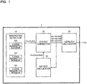
- Fig. 1 is a block diagram showing an overall configuration of an azimuth sensor 1.
- the azimuth sensor 1 of this configuration example includes a magnetism detector 10, an offset corrector 20, an offset calculator 30, and an azimuth calculator 40.
- the magnetism detector 10 includes a magnetic sensor 10X which detects magnetism in the X-axis direction, a magnetic sensor 10Y which detects magnetism in the Y-axis direction, and a magnetic sensor 10Z which detects magnetism in the Z-axis direction, and generates three-axis magnetism detection data (Hx, Hy, Hz).
- the magnetic sensors 10X, 10Y, and 10Z each comprise a magnetism detection element, which is, for example, a Hall-effect device or an MR (magnetoresistance) device.
- the X-, Y-, and Z-axes are designed to be perpendicular to each other.
- the offset corrector 20 corrects the magnetism detection data (Hx, Hy, Hz) by using offset values calculated by the offset calculator 30 (which are offset components (HxO, Hy0, Hz0) contained in three-axis magnetism detection data (Hx, Hy, Hz) respectively).
- the offset calculator 30 constantly monitors the offset-corrected magnetism detection data (Hx, Hy, Hz), and sequentially updates the offset values (HxO, Hy0, Hz0) for the magnetism detector 10.
- the offset calculation processing offset updating processing
- the azimuth calculator 40 generates azimuth data So from the offset-corrected magnetism detection data (Hx, Hy, Hz).
- the offset corrector 20, the offset calculator 30, and the azimuth calculator 40 are shown as mutually independent processing blocks; instead, these processing blocks may be implemented in an integrated fashion by use of a CPU (central processing unit), a DSP (digital signal processor), or the like.
- CPU central processing unit
- DSP digital signal processor
- Fig. 2 is an XYZ coordinate space diagram showing a first example of the offset calculation processing in the offset calculator 30.
- the magnetism detector 10 has high precision, sufficient offset calculation accuracy is achieved without unnecessary increasing the number of data points.
- the data points PI to P7 are translated evenly such that one reference data point arbitrarily selected from the data points PI to P7 coincides with the origin O (0, 0, 0).
- the data point P7 is selected as the reference data point.
- a virtual offset point C' that minimizes the sum of the distances from a curved surface HI passing through the origin O to the virtual data points P1' to P6' respectively is calculated.
- H 1 ⁇ i Hxi ' 2 + Hyi ' 2 + Hzi ' 2 ⁇ 2 Hxi ' ⁇ Hx 0 ' ⁇ 2 Hyi ' ⁇ Hy 0 ' ⁇ 2 Hzi ' ⁇ Hz 0 ' 2
- the virtual offset point C' is translated inversely to the previous translation, and thereby the proper offset point C (HxO, Hy0, Hz0) (corresponding to the offset values for the magnetism detector 10) is calculated.
- the offset calculation processing of this example adopts the following calculation method: a curved surface is assumed that necessarily passes an arbitrary one of N data points that are referred to; thereby the equation of the curved surface simpler than the equation of a spherical surface is derived; then the parameters of the derived equation are estimated from the remaining (N - 1) data points.
- a virtual offset point C' that minimizes the sum of the distances from a curved line H2 passing through the origin O (0, 0) to the virtual data points Pi' respectively can be calculated.
- the virtual data points Pi' are represented by (Hxi', Hyi')
- the virtual offset point C' is represented by (Hx0', Hy0')
- a virtual offset point C' that minimizes the equation of the curved line H2 given by formula (2) below is calculated.
- H 2 ⁇ i Hxi ' 2 + Hyi ' 2 ⁇ 2 Hxi ' ⁇ Hx 0 ' ⁇ 2 Hyi ' ⁇ Hy 0 ' 2
- Fig. 3 is a flow chart showing a second example of the offset calculation processing in the offset calculator 30.
- preprocessing corresponding to steps S1 to S4 in Fig. 3 for determining a data point group that is appropriate as the target of reference is introduced.
- a detailed step-by-step description will follow. It is assumed that, unless otherwise stated, the agent of the steps is the offset calculator 30.
- offset values (Hx0, Hy0, Hz0) are set or updated.
- the initial values are (0, 0, 0).
- the agent of step S2 is the offset corrector 20.
- step S3 with reference to the offset-corrected magnetism detection data (Hx, Hy, and Hz), a total of six data points of the maximum and minimum values for the three axes are constantly searched for.
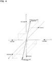
- Fig. 4 is an XYZ coordinate space diagram showing the maximum and minimum values for the three axes.
- the maximum value of the X-axis component is Hx(max)
- the corresponding X-axis maximum data point is Pa(Hx(max), *, *).
- the minimum value of the X-axis component is Hx(min)
- the corresponding X-axis minimum data point is Pb(Hx(min), *, *).
- step S4 whether or not the difference values ⁇ Hx, ⁇ Hy, ⁇ Hz between the maximum and minimum values for the respective axes are equal to or larger than threshold values is checked. For example, if ⁇ Hx ⁇ THx, ⁇ Hy ⁇ THy, and ⁇ Hz ⁇ THz, the check result is "yes", and if any of those inequalities is not fulfilled, the check result is "no".
- step S4 if the check result is "yes”, the flow proceeds to step S5 and, if the check result is "no", the flow returns to S3.
- the threshold values THx to THz for the respective axes are set at, for example, about 30 ⁇ T.
- the threshold values THx to THz for the respective axes may be equal, or may be different from each other.
- step S4 If the check result of step S4 is "no", the flow repeats the loop of steps S3 and S4. That is, until the difference values ⁇ Hx, ⁇ Hy, ⁇ Hz for the respective axes are equal to or larger than the threshold value, the maximum and minimum values for the three axes continue being searched for.
- Fig. 5 is a time chart showing the variation behavior of the difference value ⁇ Hx for the X axis. Tracking the data points indicated by the symbols Pa0 to Pa3 and Pb0 to Pb4 reveals how the X-axis maximum and minimum data points Pa and Pb go being updated successively as time passes. Naturally, the difference value ⁇ Hx for the X axis becomes larger each time at least one of the maximum and minimum values Hx(max) and Hx(min) of the X-axis component is updated.
- step S4 If the check result of step S4 is "yes”, the offset calculation processing (corresponding to steps S5 to S7 in Fig. 3 ) of the first example described previously is executed. That is, in the offset calculator 30, when the differences between the maximum and minimum values for the respective axes are all equal to or larger than the threshold values, it is recognized that a data point group that is appropriate as the target of reference in offset calculation (a group of data points that are considered to be comparatively evenly distributed in the XYZ coordinate space centered at the offset point C) has been collected, and the offset calculation processing described previously is executed.
- a data point group that is appropriate as the target of reference in offset calculation (a group of data points that are considered to be comparatively evenly distributed in the XYZ coordinate space centered at the offset point C) has been collected, and the offset calculation processing described previously is executed.
- Adopting this algorithm helps prevent the risk of acquiring an inappropriate offset calculation result from an unevenly distributed data point group, and thus helps enhance the reliability of offset calculation processing.
- step S5 as one step of the offset calculation processing described previously, the maximum and minimum data points for the respective axes are translated such that one arbitrary point different from any of the maximum and minimum data points for the respective axes is translated to the origin O (0, 0, 0).
- all the data points that are subjected to actual calculation in the offset calculation processing of the second example are six points comprising the maximum and minimum data points for the respective axes and one point different from any of them (corresponding to the reference data point mentioned previously). Accordingly, the offset calculator 30 has only to be provided with a total of seven registers, and thus, compared with the conventional configuration, which requires 10 or more data points, it is possible to greatly reduce the circuit scale or the software code size.
- Fig. 6 is a timing chart showing an example of the selection of a reference data point that is translated to the origin (0, 0, 0).
- solid circles represent the maximum and minimum data points (a total of six points) corresponding to the maximum and minimum values for the three axes.
- hollow circles represent data points other than those six points.
- step S6 from the six points that have undergone translation at step S5, a virtual offset point C' (Hx0', Hy0', Hz0') that minimizes the equation of the curved surface HI given by formula (1) noted previously is derived. This has been described in detail previously, and therefore no overlapping description will be repeated.
- step S7 the six points of the maximum and minimum values for the three axes are cleared, and the offset point C (Hx0, Hy0, Hz0) translated inversely to the previous translation is calculated as the offset values for the magnetism detector 10.
- step S1 the flow returns to step S1, so that the above-described sequence of processing is repeated.
- the offsets for the azimuth sensor 1 which constantly change both temporally and spatially keep being canceled continuously and at high speed, and it is thus possible to detect the azimuth accurately.
- the reference data point may instead be one of the maximum and minimum data points for the respective axes.
- This configuration helps reduce by one the number of data points that are subjected to actual calculation in offset calculation processing, and thus helps further reduce the circuit scale or the software code size.
- adopting this configuration may lead to lower offset calculation accuracy.
- Fig. 7 is an XYZ coordinate space diagram illustrating a point to be noted when a data point corresponding to one of the maximum and minimum values for the three axes is selected as a reference data point. It can occur that, under the influence of an extraneous magnetic field or the like, one of the maximum and minimum values for the respective axes (in the illustrated example, the maximum value Hx(max) of the X-axis component deviates greatly from the others).
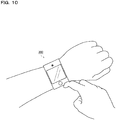
- Figs. 8 to 10 are exterior views of examples of electronic appliances (a smartphone 100, a tablet terminal 200, and a smartwatch 300 respectively) incorporating the azimuth sensor 1.
- Incorporating the azimuth sensor 1 described previously as an electronic compass in a variety of appliances makes it possible to accurately detect the direction in which the user points.
- using the electronic compass in combination with a GPS (global positioning system) helps enhance the accuracy of position detection in map and navigation applications.
- the invention disclosed herein finds applications in azimuth sensors incorporated in, for example, smartphones, tablet terminals, smartwatches, and the like.
Landscapes
- Physics & Mathematics (AREA)
- Engineering & Computer Science (AREA)
- Radar, Positioning & Navigation (AREA)
- Remote Sensing (AREA)
- General Physics & Mathematics (AREA)
- Condensed Matter Physics & Semiconductors (AREA)
- Electromagnetism (AREA)
- Measuring Magnetic Variables (AREA)
Description
- The present invention relates to an offset calculation device, and to an azimuth sensor employing it.
- An azimuth sensor (geomagnetism sensor) detects the direction of geomagnetism and thereby measures an azimuth. Here, the geomagnetism as the target of measurement is extremely feeble. Accordingly, for accurate detection of the azimuth, it is necessary to detect the true geomagnetism by canceling offsets ascribable to magnetic fields present in the environment (one produced inside the set that incorporates the azimuth sensor, one produced by a strong magnet or the like placed near the azimuth sensor, and the like) and offsets ascribable to the performance of the azimuth sensor itself.
- Offsets for an azimuth sensor constantly vary both temporally and spatially. Accordingly, for accurate detection of an azimuth, it is necessary to keep canceling the offsets for the azimuth sensor continuously and at high speed.
- Offsets can be corrected either manually by the user doing it consciously or automatically without the user being conscious of it. For better user-friendliness and enhanced detection accuracy of the azimuth sensor, automatic correction is preferred.
- One example of conventional technology related to what is discussed above is seen in
Patent Document 1 identified below. - Patent Document 1: Japanese Patent registered as No.
4391416 - Inconveniently, with the conventional technology disclosed in
Patent Document 1, offset correction processing requires a large amount of computation; to keep canceling offsets continuously and at high speed, high computing power is essential. - In view of the above-mentioned problems encountered by the present inventors, an object of the present invention is to provide an offset calculation device that can calculate offsets with a smaller amount of computation than ever and an azimuth sensor that employs such an offset calculation device.
- According to one aspect of what is disclosed herein, an offset calculation device for processing three-axis or two-axis magnetism detection data sequentially acquired as data points in a three-axis or two-axis coordinate system is configured to translate N data points (where N ≥ 2) evenly such that one reference data point arbitrarily selected from the N data points coincides with the origin to derive (N-1) virtual data points except for the reference data point, then calculate a virtual offset point that minimizes the sum of the distances from a curved surface or curved line passing through the origin to the virtual data points respectively, and then calculate offset values for the magnetism detection data by translating the virtual offset point inversely the previous translation (a first configuration).
- The offset calculation device according to the first configuration described above may be configured such that, when the virtual data points are represented by (Hxi', Hyi', Hzi') (where i = 1 to N-1), and the virtual offset point is represented by (Hx0', Hy0', Hz0'), it calculates the virtual offset point such as to minimize the equation of the curved surface given by formula (1) below (a second configuration).
[Equation 1]
- Instead, the offset calculation device according to the first configuration described above may be configured such that, when the virtual data points are represented by (Hxi', Hyi') (where i = 1 to N-1), and the virtual offset point is represented by (Hx0', Hy0'), it calculates the virtual offset point such as to minimize the equation of the curved line given by formula (2) below (a third configuration).
[Equation 2]
- The offset calculation device according to any one of the first to third configurations may be configured to constantly search, by referring to offset-corrected magnetism detection data, for a plurality of maximum and minimum data points corresponding to the maximum and minimum values for the respective axes and, when all the differences between the maximum and minimum values for the respective axes are equal to or larger than respective threshold values, execute a sequence of offset calculation processing (a fourth configuration).
- In the offset calculation device according to the fourth configuration above, the N data points may include the plurality of maximum and minimum data points (a fifth configuration).
- In the offset calculation device according to the fifth configuration above, the reference data point may be an arbitrary point different from any of the plurality of maximum and minimum data points (a sixth configuration).
- In the offset calculation device according to the fifth configuration above, the reference data point may be one of the plurality of maximum and minimum data points (a seventh configuration).
- According to another aspect of what is disclosed herein, an azimuth sensor includes: a magnetism detection device configured to generate three-axis or two-axis magnetism detection data; an offset calculation device according to any one of the first to seventh configurations described above configured to calculate an offset for the magnetism detection data; an offset correction device configured to correct the offset for the magnetism detection data; and an azimuth calculation device configured to generate azimuth data from corrected magnetism detection data (an eighth configuration).
- According to yet another aspect of what is disclosed herein, an electronic appliance includes the azimuth sensor according to the eighth configuration (a ninth configuration).
- According to still another aspect of what is disclosed herein, an offset calculation method for processing three-axis or two-axis magnetism detection data sequentially acquired as data points in a three-axis or two-axis coordinate system includes: translating N data points (where N ≥ 2) evenly such that one reference data point arbitrarily selected from the N data points coincides with the origin to derive (N-1) virtual data points except for the reference data point; calculating a virtual offset point that minimizes the sum of the distances from a curved surface or curved line passing through the origin to the virtual data points respectively; and calculating offset values for the magnetism detection data by translating the virtual offset point inversely to the previous translation (a tenth configuration).
- According to the invention disclosed herein, it is possible to provide an offset calculation device that can calculate offsets with a smaller amount of computation than ever and an azimuth sensor that employs such an offset calculation device.
-
-
Fig. 1 is a block diagram showing an overall configuration of anazimuth sensor 1;Fig. 2 is an XYZ coordinate space diagram showing a first example of offset calculation processing; -
Fig. 3 is a flow chart showing a second example of offset calculation processing; -
Fig. 4 is an XYZ coordinate space diagram showing maximum and minimum values for three axes; -
Fig. 5 is a timing chart showing variation behavior of a difference value ΔHx; -
Fig. 6 is a timing chart showing an example of selection of a reference data point that is translated to an origin; -
Fig. 7 is an XYZ coordinate space diagram illustrating a point to be noted when a data point corresponding to one of maximum and minimum values for three axes is selected as a reference data point; -
Fig. 8 is an exterior view of a smartphone; -
Fig. 9 is an exterior view of a tablet terminal; and -
Fig. 10 is an exterior view of a smartwatch. -
Fig. 1 is a block diagram showing an overall configuration of anazimuth sensor 1. Theazimuth sensor 1 of this configuration example includes amagnetism detector 10, anoffset corrector 20, anoffset calculator 30, and anazimuth calculator 40. - The
magnetism detector 10 includes amagnetic sensor 10X which detects magnetism in the X-axis direction, amagnetic sensor 10Y which detects magnetism in the Y-axis direction, and a magnetic sensor 10Z which detects magnetism in the Z-axis direction, and generates three-axis magnetism detection data (Hx, Hy, Hz). Themagnetic sensors - The
offset corrector 20 corrects the magnetism detection data (Hx, Hy, Hz) by using offset values calculated by the offset calculator 30 (which are offset components (HxO, Hy0, Hz0) contained in three-axis magnetism detection data (Hx, Hy, Hz) respectively). The offset correction processing yields Hx = Hx - Hx0, Hy = Hy - Hy0, and Hy = Hz - Hz0. - The
offset calculator 30 constantly monitors the offset-corrected magnetism detection data (Hx, Hy, Hz), and sequentially updates the offset values (HxO, Hy0, Hz0) for themagnetism detector 10. The offset calculation processing (offset updating processing) will be described in detail later. - The
azimuth calculator 40 generates azimuth data So from the offset-corrected magnetism detection data (Hx, Hy, Hz). - In
Fig. 1 , theoffset corrector 20, theoffset calculator 30, and theazimuth calculator 40 are shown as mutually independent processing blocks; instead, these processing blocks may be implemented in an integrated fashion by use of a CPU (central processing unit), a DSP (digital signal processor), or the like. -
Fig. 2 is an XYZ coordinate space diagram showing a first example of the offset calculation processing in theoffset calculator 30. In the offset calculation processing of the first example, with respect to three-axis magnetism detection data (Hx, Hy, Hz) successively acquired as three-axis coordinate data points, N data points (where N ≥ 2; in the illustrated example, a total of 7 data points PI to P7 (N = 7)) are referred to. In a case where themagnetism detector 10 has high precision, sufficient offset calculation accuracy is achieved without unnecessary increasing the number of data points. - Next, the data points PI to P7 are translated evenly such that one reference data point arbitrarily selected from the data points PI to P7 coincides with the origin O (0, 0, 0). In the illustrated example, the data point P7 is selected as the reference data point. Through the translation, except for the reference data point P7, six (= N - 1) virtual data points P1' to P6' are derived.
- Next, a virtual offset point C' that minimizes the sum of the distances from a curved surface HI passing through the origin O to the virtual data points P1' to P6' respectively is calculated. Specifically, when the virtual data points Pi' are represented by (Hxi', Hyi', Hzi') (in the illustrated example, i = 1 to 6), and the virtual offset point C' is represented by (Hx0', Hy0', Hz0'), then a virtual offset point C' that minimizes the equation of the curved surface HI given by formula (1) below is calculated.
[Equation 3]
- Note that the equation of the curved surface HI given by formula (1) above is derived on the assumption that a spherical surface with a radius r centered at the virtual offset point C' passes through the origin O (r = |OC'|).
- Lastly, the virtual offset point C' is translated inversely to the previous translation, and thereby the proper offset point C (HxO, Hy0, Hz0) (corresponding to the offset values for the magnetism detector 10) is calculated.
- As described above, the offset calculation processing of this example adopts the following calculation method: a curved surface is assumed that necessarily passes an arbitrary one of N data points that are referred to; thereby the equation of the curved surface simpler than the equation of a spherical surface is derived; then the parameters of the derived equation are estimated from the remaining (N - 1) data points.
- This, unlike the conventional technique that directly applies the equation of a spherical surface to calculate offset values, requires no complicated calculation (such as average value calculation), and thus makes it possible to reduce the amount of computation required for the offset correction processing and cancel offsets continuously and at high speed.
- Although the detailed description given above deals with an example where three-axis magnetism detection data (Hx, Hy, Hz) is the target of offset correction, the offset calculation method described above can be applied also to a case where two-axis magnetism detection data (Hx, Hy) is the target of offset correction.
- In that case, a virtual offset point C' that minimizes the sum of the distances from a curved line H2 passing through the origin O (0, 0) to the virtual data points Pi' respectively can be calculated. Specifically, when the virtual data points Pi' are represented by (Hxi', Hyi'), and the virtual offset point C' is represented by (Hx0', Hy0'), then a virtual offset point C' that minimizes the equation of the curved line H2 given by formula (2) below is calculated.
[Equation 4]
-
Fig. 3 is a flow chart showing a second example of the offset calculation processing in the offsetcalculator 30. In the offset calculation processing of the second example, before the execution of the offset calculation processing (corresponding to steps S5 to S7 inFig. 3 ) of the first example, preprocessing (corresponding to steps S1 to S4 inFig. 3 ) for determining a data point group that is appropriate as the target of reference is introduced. A detailed step-by-step description will follow. It is assumed that, unless otherwise stated, the agent of the steps is the offsetcalculator 30. - First, at step S1, offset values (Hx0, Hy0, Hz0) are set or updated. The initial values are (0, 0, 0).
- Next, at step S2, three-axis magnetism detection data (Hx, Hy, and Hz) are constantly acquired, and are subjected to offset correction (Hx = Hx - Hx0, Hy = Hy - Hy0, and Hy = Hz - Hz0). The agent of step S2 is the offset
corrector 20. - Next, at step S3, with reference to the offset-corrected magnetism detection data (Hx, Hy, and Hz), a total of six data points of the maximum and minimum values for the three axes are constantly searched for.
-
Fig. 4 is an XYZ coordinate space diagram showing the maximum and minimum values for the three axes. In the illustrated example, the maximum value of the X-axis component is Hx(max), and the corresponding X-axis maximum data point is Pa(Hx(max), *, *). On the other hand, the minimum value of the X-axis component is Hx(min), and the corresponding X-axis minimum data point is Pb(Hx(min), *, *). - Although not specifically shown in
Fig. 3 , also for the maximum and minimum values Hy(max) and Hy(min) of the Y-axis component and the maximum and minimum values of the Z-axis component Hz(max) and Hz(min), the maximum and minimum data points for the respective axes, like those mentioned above, exist. - With reference back to
Fig. 3 , the description of the flow will continue. At step S4, whether or not the difference values ΔHx, ΔHy, ΔHz between the maximum and minimum values for the respective axes are equal to or larger than threshold values is checked. For example, if ΔHx ≥ THx, ΔHy ≥ THy, and ΔHz ≥ THz, the check result is "yes", and if any of those inequalities is not fulfilled, the check result is "no". At step S4, if the check result is "yes", the flow proceeds to step S5 and, if the check result is "no", the flow returns to S3. - In view of the magnitude of geomagnetism as the target of measurement (20 to 80 µT in general, 40 to 50 µT in Japan), it is preferable to set the threshold values THx to THz for the respective axes at, for example, about 30 µT. The threshold values THx to THz for the respective axes may be equal, or may be different from each other.
- If the check result of step S4 is "no", the flow repeats the loop of steps S3 and S4. That is, until the difference values ΔHx, ΔHy, ΔHz for the respective axes are equal to or larger than the threshold value, the maximum and minimum values for the three axes continue being searched for.
-
Fig. 5 is a time chart showing the variation behavior of the difference value ΔHx for the X axis. Tracking the data points indicated by the symbols Pa0 to Pa3 and Pb0 to Pb4 reveals how the X-axis maximum and minimum data points Pa and Pb go being updated successively as time passes. Naturally, the difference value ΔHx for the X axis becomes larger each time at least one of the maximum and minimum values Hx(max) and Hx(min) of the X-axis component is updated. - With reference back to
Fig. 3 , the description of the flow will continue. If the check result of step S4 is "yes", the offset calculation processing (corresponding to steps S5 to S7 inFig. 3 ) of the first example described previously is executed. That is, in the offsetcalculator 30, when the differences between the maximum and minimum values for the respective axes are all equal to or larger than the threshold values, it is recognized that a data point group that is appropriate as the target of reference in offset calculation (a group of data points that are considered to be comparatively evenly distributed in the XYZ coordinate space centered at the offset point C) has been collected, and the offset calculation processing described previously is executed. - Adopting this algorithm helps prevent the risk of acquiring an inappropriate offset calculation result from an unevenly distributed data point group, and thus helps enhance the reliability of offset calculation processing.
- At step S5, as one step of the offset calculation processing described previously, the maximum and minimum data points for the respective axes are translated such that one arbitrary point different from any of the maximum and minimum data points for the respective axes is translated to the origin O (0, 0, 0).
- That is, all the data points that are subjected to actual calculation in the offset calculation processing of the second example are six points comprising the maximum and minimum data points for the respective axes and one point different from any of them (corresponding to the reference data point mentioned previously). Accordingly, the offset
calculator 30 has only to be provided with a total of seven registers, and thus, compared with the conventional configuration, which requires 10 or more data points, it is possible to greatly reduce the circuit scale or the software code size. -
Fig. 6 is a timing chart showing an example of the selection of a reference data point that is translated to the origin (0, 0, 0). In the diagram, solid circles represent the maximum and minimum data points (a total of six points) corresponding to the maximum and minimum values for the three axes. On the other hand, hollow circles represent data points other than those six points. - For example, as shown in
Fig. 6 , when, as a result of a continuous search for the maximum and minimum values for the three axes from the data point PI to the data point Pk, all the maximum and minimum data points for the respective axes are determined, from the viewpoint of adopting the simplest algorithm for reference data point selection, it is preferable to select the data point Pk+1 acquired immediately after the data point Pk. This, however, is not meant to exclude selecting any one of data points PI to Pk-1 (excluding the maximum and minimum data points) as the reference data point. - With reference back to
Fig. 3 , the description of the flow will continue. At step S6, from the six points that have undergone translation at step S5, a virtual offset point C' (Hx0', Hy0', Hz0') that minimizes the equation of the curved surface HI given by formula (1) noted previously is derived. This has been described in detail previously, and therefore no overlapping description will be repeated. - Next, at step S7, the six points of the maximum and minimum values for the three axes are cleared, and the offset point C (Hx0, Hy0, Hz0) translated inversely to the previous translation is calculated as the offset values for the
magnetism detector 10. - Thereafter, the flow returns to step S1, so that the above-described sequence of processing is repeated. As a result, the offsets for the
azimuth sensor 1 which constantly change both temporally and spatially keep being canceled continuously and at high speed, and it is thus possible to detect the azimuth accurately. - Although the above description deals with an example where, at step S5, one arbitrary point different from any of the maximum and minimum data points for the respective axes is selected as a reference data point that is translated to the origin O (0, 0, 0), the reference data point may instead be one of the maximum and minimum data points for the respective axes. This configuration helps reduce by one the number of data points that are subjected to actual calculation in offset calculation processing, and thus helps further reduce the circuit scale or the software code size. However, depending on how the maximum and minimum data points for the respective axes are distributed, adopting this configuration may lead to lower offset calculation accuracy.
-
Fig. 7 is an XYZ coordinate space diagram illustrating a point to be noted when a data point corresponding to one of the maximum and minimum values for the three axes is selected as a reference data point. It can occur that, under the influence of an extraneous magnetic field or the like, one of the maximum and minimum values for the respective axes (in the illustrated example, the maximum value Hx(max) of the X-axis component deviates greatly from the others). - If a maximum or minimum data point that deviates greatly from the others is selected as a reference data point, the amount of translation required to make the reference data point coincide with the origin deviates greatly from the proper value. This makes it impossible to obtain correct offset values C through the offset calculation processing described previously.
- To avoid this inconvenience, it is preferable, for example, to take measures such as excluding, of the six data points corresponding to the maximum and minimum values for the three axes, those of which the respective axis components have the largest and smallest absolute values from candidates for the reference data point.
-
Figs. 8 to 10 are exterior views of examples of electronic appliances (asmartphone 100, atablet terminal 200, and asmartwatch 300 respectively) incorporating theazimuth sensor 1. Incorporating theazimuth sensor 1 described previously as an electronic compass in a variety of appliances makes it possible to accurately detect the direction in which the user points. In particular, using the electronic compass in combination with a GPS (global positioning system) helps enhance the accuracy of position detection in map and navigation applications. - The various technical features disclosed herein may be implemented in any other manner than specifically described by way of embodiments above, and allows for many modifications within the scope of the technical ingenuity of the invention. That is, the embodiments described above should be considered to be in every aspect illustrative and not restrictive, and the technical scope of the present invention should be understood to be defined not by the description of embodiments given above but by the appended claims and to encompasses any modifications in the sense and scope equivalent to those of the claims.
- The invention disclosed herein finds applications in azimuth sensors incorporated in, for example, smartphones, tablet terminals, smartwatches, and the like.
-
- 1
- azimuth sensor
- 10
- magnetism detector
- 10X, 10Y, 10Z
- magnetic sensor (X-axis, Y-axis, Z-axis)
- 20
- offset corrector
- 30
- offset calculator
- 40
- azimuth calculator
- 100
- smartphone
- 200
- tablet terminal
- 300
- smartwatch
Claims (3)
- An offset calculation device for processing three-axis or two-axis magnetism detection data sequentially acquired as data points in a three-axis or two-axis coordinate system, the offset calculation device being configured to
translate N data points (where N ≥ 2) evenly such that one reference data point arbitrarily selected from the N data points coincides with an origin to derive (N-1) virtual data points except for the reference data point,
calculate a virtual offset point that minimizes a sum of distances from a curved surface or curved line passing through the origin to the virtual data points respectively, and
calculate offset values for the magnetism detection data by translating the virtual offset point inversely to previous translation. - The offset calculation device of claim 1, wherein
when the virtual data points are represented by (Hxi', Hyi', Hzi') (where i = 1 to N-1), and the virtual offset point is represented by (Hx0', Hy0', Hz0'),
the offset calculation device is configured to calculate the virtual offset point such as to minimize an equation of the curved surface given by formula (1) below.
[Equation 1]
- The offset calculation device of claim 1, wherein
when the virtual data points are represented by (Hxi', Hyi') (where i = 1 to N-1), and the virtual offset point is represented by (Hx0', Hy0'),
the offset calculation device is configured to calculate the virtual offset point such as to minimize an equation of the curved line given by formula (1) below.
[Equation 2]
Applications Claiming Priority (2)
| Application Number | Priority Date | Filing Date | Title |
|---|---|---|---|
| JP2015006770A JP6430262B2 (en) | 2015-01-16 | 2015-01-16 | Offset calculation apparatus and azimuth angle sensor using the same |
| PCT/JP2015/083907 WO2016114027A1 (en) | 2015-01-16 | 2015-12-02 | Offset detection device and azimuth angle sensor |
Publications (3)
| Publication Number | Publication Date |
|---|---|
| EP3258216A1 true EP3258216A1 (en) | 2017-12-20 |
| EP3258216A4 EP3258216A4 (en) | 2018-11-21 |
| EP3258216B1 EP3258216B1 (en) | 2019-09-25 |
Family
ID=56405583
Family Applications (1)
| Application Number | Title | Priority Date | Filing Date |
|---|---|---|---|
| EP15877978.5A Not-in-force EP3258216B1 (en) | 2015-01-16 | 2015-12-02 | Offset detection device and azimuth angle sensor |
Country Status (6)
| Country | Link |
|---|---|
| US (1) | US10753741B2 (en) |
| EP (1) | EP3258216B1 (en) |
| JP (1) | JP6430262B2 (en) |
| KR (1) | KR101928231B1 (en) |
| CN (1) | CN107209014B (en) |
| WO (1) | WO2016114027A1 (en) |
Families Citing this family (3)
| Publication number | Priority date | Publication date | Assignee | Title |
|---|---|---|---|---|
| JP6841827B2 (en) | 2016-07-05 | 2021-03-10 | デンカ株式会社 | A one-component water-based adhesive comprising a latex composition and the latex composition |
| JP6581144B2 (en) * | 2017-04-28 | 2019-09-25 | 株式会社東芝 | Satellite capture device and satellite capture method |
| JP7025215B2 (en) | 2018-01-05 | 2022-02-24 | ローム株式会社 | Positioning system and positioning method |
Family Cites Families (12)
| Publication number | Priority date | Publication date | Assignee | Title |
|---|---|---|---|---|
| EP0214817B1 (en) * | 1985-09-03 | 1991-12-04 | British Aerospace Public Limited Company | Calibration of magnetic compasses |
| JP4026937B2 (en) | 1998-06-29 | 2007-12-26 | 古野電気株式会社 | Electronic magnetic compass |
| US7177779B2 (en) | 2002-07-01 | 2007-02-13 | Asahi Kasei Emd Corporation | Azimuth measuring device and azimuth measuring method |
| EP1698857B1 (en) | 2003-12-22 | 2009-11-25 | Asahi Kasei EMD Corporation | Azimuth measurement device |
| KR100847382B1 (en) * | 2004-08-10 | 2008-07-18 | 야마하 가부시키가이샤 | Azimuth data producing method, azimuth sensor unit and portable electronic device |
| JP4899525B2 (en) * | 2006-02-21 | 2012-03-21 | ヤマハ株式会社 | Magnetic sensor control device, magnetic measurement device, offset setting method and program |
| JP2008128649A (en) * | 2006-11-16 | 2008-06-05 | Citizen Holdings Co Ltd | Azimuth sensor and recording medium |
| WO2008111445A1 (en) * | 2007-03-06 | 2008-09-18 | Alps Electric Co., Ltd. | Direction calculation program and electronic compass |
| WO2008146757A1 (en) * | 2007-05-24 | 2008-12-04 | Asahi Kasei Emd Corporation | Physical amount measuring device and physical amount measuring method |
| JP5498209B2 (en) * | 2010-03-10 | 2014-05-21 | アルプス電気株式会社 | Magnetic field detector |
| DE102010029668A1 (en) | 2010-06-02 | 2011-12-08 | Robert Bosch Gmbh | Calibration of a three-axis magnetic field sensor |
| US9031805B2 (en) * | 2011-03-22 | 2015-05-12 | Yamaha Corporation | Geomagnetic field measurement device, offset determination method, and computer readable recording medium therefor |
-
2015
- 2015-01-16 JP JP2015006770A patent/JP6430262B2/en active Active
- 2015-12-02 CN CN201580073548.1A patent/CN107209014B/en not_active Expired - Fee Related
- 2015-12-02 EP EP15877978.5A patent/EP3258216B1/en not_active Not-in-force
- 2015-12-02 WO PCT/JP2015/083907 patent/WO2016114027A1/en not_active Ceased
- 2015-12-02 KR KR1020177019627A patent/KR101928231B1/en not_active Expired - Fee Related
- 2015-12-02 US US15/542,975 patent/US10753741B2/en active Active
Also Published As
| Publication number | Publication date |
|---|---|
| US10753741B2 (en) | 2020-08-25 |
| KR20170095991A (en) | 2017-08-23 |
| CN107209014A (en) | 2017-09-26 |
| EP3258216B1 (en) | 2019-09-25 |
| WO2016114027A1 (en) | 2016-07-21 |
| KR101928231B1 (en) | 2018-12-11 |
| JP2016133343A (en) | 2016-07-25 |
| CN107209014B (en) | 2020-01-14 |
| US20180003500A1 (en) | 2018-01-04 |
| JP6430262B2 (en) | 2018-11-28 |
| EP3258216A4 (en) | 2018-11-21 |
Similar Documents
| Publication | Publication Date | Title |
|---|---|---|
| US7844415B1 (en) | Dynamic motion compensation for orientation instrumentation | |
| US20060066295A1 (en) | Control method of controlling magnetic-field sensor, control device, and mobile terminal device | |
| US20170336208A1 (en) | Attitude estimating device, attitude estimating method, and storage medium | |
| CN110988926B (en) | Method for realizing position accurate fixed point deception migration in loose GNSS/INS combined navigation mode | |
| WO2014010727A1 (en) | Device for estimating moving object travel direction and method for estimating travel direction | |
| US8812225B2 (en) | Electronic navigation device for a human and related methods | |
| CN103575293A (en) | Magnetometer direction angle correction method and magnetometer | |
| EP3258216B1 (en) | Offset detection device and azimuth angle sensor | |
| CN114485641A (en) | Attitude calculation method and device based on inertial navigation and satellite navigation azimuth fusion | |
| US11709056B2 (en) | Method and device for magnetic field measurement by magnetometers | |
| US9863867B2 (en) | Automatically updating hard iron and soft iron coefficients of a magnetic sensor | |
| JP2019120587A (en) | Positioning system and positioning method | |
| US11079224B2 (en) | Offset derivation device, offset calculation device, and azimuth sensor | |
| CN102721416B (en) | A kind of method of location and mobile terminal | |
| JP5475873B2 (en) | Geomagnetic detector | |
| JP2012212234A (en) | Portable device, program and method for correcting gravity vector to be used for autonomous positioning | |
| Reis et al. | Calibration of high-grade inertial measurement units using a rate table | |
| EP4174438A1 (en) | System and method for determining geographic location of a device | |
| Oh et al. | Method to determine initial aiming azimuth accuracy using acceleration, gyroscope, and geomagnetic sensors | |
| JP2015102330A (en) | Movement information calculation device, movement information calculation method, movement information calculation program, and mobile body | |
| US20160169673A1 (en) | Offset calculation circuit and azimuth sensor using the same | |
| US20230128046A1 (en) | Detection method and computer-readable recording medium storing detection program | |
| US11112243B2 (en) | Electronic compass | |
| JP4947669B2 (en) | Azimuth angle measuring method and azimuth angle measuring apparatus | |
| JP2016109609A (en) | Posture estimation device and control program for posture estimation device |
Legal Events
| Date | Code | Title | Description |
|---|---|---|---|
| STAA | Information on the status of an ep patent application or granted ep patent |
Free format text: STATUS: THE INTERNATIONAL PUBLICATION HAS BEEN MADE |
|
| PUAI | Public reference made under article 153(3) epc to a published international application that has entered the european phase |
Free format text: ORIGINAL CODE: 0009012 |
|
| STAA | Information on the status of an ep patent application or granted ep patent |
Free format text: STATUS: REQUEST FOR EXAMINATION WAS MADE |
|
| 17P | Request for examination filed |
Effective date: 20170629 |
|
| AK | Designated contracting states |
Kind code of ref document: A1 Designated state(s): AL AT BE BG CH CY CZ DE DK EE ES FI FR GB GR HR HU IE IS IT LI LT LU LV MC MK MT NL NO PL PT RO RS SE SI SK SM TR |
|
| AX | Request for extension of the european patent |
Extension state: BA ME |
|
| DAV | Request for validation of the european patent (deleted) | ||
| DAX | Request for extension of the european patent (deleted) | ||
| A4 | Supplementary search report drawn up and despatched |
Effective date: 20181018 |
|
| RIC1 | Information provided on ipc code assigned before grant |
Ipc: G01R 33/02 20060101ALI20181012BHEP Ipc: G01C 17/32 20060101ALI20181012BHEP Ipc: G01C 17/38 20060101AFI20181012BHEP |
|
| GRAP | Despatch of communication of intention to grant a patent |
Free format text: ORIGINAL CODE: EPIDOSNIGR1 |
|
| STAA | Information on the status of an ep patent application or granted ep patent |
Free format text: STATUS: GRANT OF PATENT IS INTENDED |
|
| RIN1 | Information on inventor provided before grant (corrected) |
Inventor name: KOBAYASHI, TADASHI Inventor name: SEIKE, MASAFUMI Inventor name: NISHIYAMA, HIDEKI |
|
| INTG | Intention to grant announced |
Effective date: 20190417 |
|
| GRAS | Grant fee paid |
Free format text: ORIGINAL CODE: EPIDOSNIGR3 |
|
| GRAA | (expected) grant |
Free format text: ORIGINAL CODE: 0009210 |
|
| STAA | Information on the status of an ep patent application or granted ep patent |
Free format text: STATUS: THE PATENT HAS BEEN GRANTED |
|
| AK | Designated contracting states |
Kind code of ref document: B1 Designated state(s): AL AT BE BG CH CY CZ DE DK EE ES FI FR GB GR HR HU IE IS IT LI LT LU LV MC MK MT NL NO PL PT RO RS SE SI SK SM TR |
|
| REG | Reference to a national code |
Ref country code: GB Ref legal event code: FG4D |
|
| REG | Reference to a national code |
Ref country code: CH Ref legal event code: EP |
|
| REG | Reference to a national code |
Ref country code: AT Ref legal event code: REF Ref document number: 1184236 Country of ref document: AT Kind code of ref document: T Effective date: 20191015 |
|
| REG | Reference to a national code |
Ref country code: IE Ref legal event code: FG4D |
|
| REG | Reference to a national code |
Ref country code: DE Ref legal event code: R096 Ref document number: 602015038867 Country of ref document: DE |
|
| REG | Reference to a national code |
Ref country code: NL Ref legal event code: MP Effective date: 20190925 |
|
| PG25 | Lapsed in a contracting state [announced via postgrant information from national office to epo] |
Ref country code: NO Free format text: LAPSE BECAUSE OF FAILURE TO SUBMIT A TRANSLATION OF THE DESCRIPTION OR TO PAY THE FEE WITHIN THE PRESCRIBED TIME-LIMIT Effective date: 20191225 Ref country code: BG Free format text: LAPSE BECAUSE OF FAILURE TO SUBMIT A TRANSLATION OF THE DESCRIPTION OR TO PAY THE FEE WITHIN THE PRESCRIBED TIME-LIMIT Effective date: 20191225 Ref country code: LT Free format text: LAPSE BECAUSE OF FAILURE TO SUBMIT A TRANSLATION OF THE DESCRIPTION OR TO PAY THE FEE WITHIN THE PRESCRIBED TIME-LIMIT Effective date: 20190925 Ref country code: HR Free format text: LAPSE BECAUSE OF FAILURE TO SUBMIT A TRANSLATION OF THE DESCRIPTION OR TO PAY THE FEE WITHIN THE PRESCRIBED TIME-LIMIT Effective date: 20190925 Ref country code: SE Free format text: LAPSE BECAUSE OF FAILURE TO SUBMIT A TRANSLATION OF THE DESCRIPTION OR TO PAY THE FEE WITHIN THE PRESCRIBED TIME-LIMIT Effective date: 20190925 Ref country code: FI Free format text: LAPSE BECAUSE OF FAILURE TO SUBMIT A TRANSLATION OF THE DESCRIPTION OR TO PAY THE FEE WITHIN THE PRESCRIBED TIME-LIMIT Effective date: 20190925 |
|
| REG | Reference to a national code |
Ref country code: LT Ref legal event code: MG4D |
|
| PG25 | Lapsed in a contracting state [announced via postgrant information from national office to epo] |
Ref country code: GR Free format text: LAPSE BECAUSE OF FAILURE TO SUBMIT A TRANSLATION OF THE DESCRIPTION OR TO PAY THE FEE WITHIN THE PRESCRIBED TIME-LIMIT Effective date: 20191226 Ref country code: RS Free format text: LAPSE BECAUSE OF FAILURE TO SUBMIT A TRANSLATION OF THE DESCRIPTION OR TO PAY THE FEE WITHIN THE PRESCRIBED TIME-LIMIT Effective date: 20190925 Ref country code: LV Free format text: LAPSE BECAUSE OF FAILURE TO SUBMIT A TRANSLATION OF THE DESCRIPTION OR TO PAY THE FEE WITHIN THE PRESCRIBED TIME-LIMIT Effective date: 20190925 |
|
| REG | Reference to a national code |
Ref country code: AT Ref legal event code: MK05 Ref document number: 1184236 Country of ref document: AT Kind code of ref document: T Effective date: 20190925 |
|
| PG25 | Lapsed in a contracting state [announced via postgrant information from national office to epo] |
Ref country code: RO Free format text: LAPSE BECAUSE OF FAILURE TO SUBMIT A TRANSLATION OF THE DESCRIPTION OR TO PAY THE FEE WITHIN THE PRESCRIBED TIME-LIMIT Effective date: 20190925 Ref country code: AL Free format text: LAPSE BECAUSE OF FAILURE TO SUBMIT A TRANSLATION OF THE DESCRIPTION OR TO PAY THE FEE WITHIN THE PRESCRIBED TIME-LIMIT Effective date: 20190925 Ref country code: IT Free format text: LAPSE BECAUSE OF FAILURE TO SUBMIT A TRANSLATION OF THE DESCRIPTION OR TO PAY THE FEE WITHIN THE PRESCRIBED TIME-LIMIT Effective date: 20190925 Ref country code: NL Free format text: LAPSE BECAUSE OF FAILURE TO SUBMIT A TRANSLATION OF THE DESCRIPTION OR TO PAY THE FEE WITHIN THE PRESCRIBED TIME-LIMIT Effective date: 20190925 Ref country code: AT Free format text: LAPSE BECAUSE OF FAILURE TO SUBMIT A TRANSLATION OF THE DESCRIPTION OR TO PAY THE FEE WITHIN THE PRESCRIBED TIME-LIMIT Effective date: 20190925 Ref country code: EE Free format text: LAPSE BECAUSE OF FAILURE TO SUBMIT A TRANSLATION OF THE DESCRIPTION OR TO PAY THE FEE WITHIN THE PRESCRIBED TIME-LIMIT Effective date: 20190925 Ref country code: ES Free format text: LAPSE BECAUSE OF FAILURE TO SUBMIT A TRANSLATION OF THE DESCRIPTION OR TO PAY THE FEE WITHIN THE PRESCRIBED TIME-LIMIT Effective date: 20190925 Ref country code: PT Free format text: LAPSE BECAUSE OF FAILURE TO SUBMIT A TRANSLATION OF THE DESCRIPTION OR TO PAY THE FEE WITHIN THE PRESCRIBED TIME-LIMIT Effective date: 20200127 Ref country code: PL Free format text: LAPSE BECAUSE OF FAILURE TO SUBMIT A TRANSLATION OF THE DESCRIPTION OR TO PAY THE FEE WITHIN THE PRESCRIBED TIME-LIMIT Effective date: 20190925 |
|
| PG25 | Lapsed in a contracting state [announced via postgrant information from national office to epo] |
Ref country code: IS Free format text: LAPSE BECAUSE OF FAILURE TO SUBMIT A TRANSLATION OF THE DESCRIPTION OR TO PAY THE FEE WITHIN THE PRESCRIBED TIME-LIMIT Effective date: 20200224 Ref country code: CZ Free format text: LAPSE BECAUSE OF FAILURE TO SUBMIT A TRANSLATION OF THE DESCRIPTION OR TO PAY THE FEE WITHIN THE PRESCRIBED TIME-LIMIT Effective date: 20190925 Ref country code: SK Free format text: LAPSE BECAUSE OF FAILURE TO SUBMIT A TRANSLATION OF THE DESCRIPTION OR TO PAY THE FEE WITHIN THE PRESCRIBED TIME-LIMIT Effective date: 20190925 Ref country code: SM Free format text: LAPSE BECAUSE OF FAILURE TO SUBMIT A TRANSLATION OF THE DESCRIPTION OR TO PAY THE FEE WITHIN THE PRESCRIBED TIME-LIMIT Effective date: 20190925 |
|
| REG | Reference to a national code |
Ref country code: DE Ref legal event code: R097 Ref document number: 602015038867 Country of ref document: DE |
|
| PG2D | Information on lapse in contracting state deleted |
Ref country code: IS |
|
| PG25 | Lapsed in a contracting state [announced via postgrant information from national office to epo] |
Ref country code: DK Free format text: LAPSE BECAUSE OF FAILURE TO SUBMIT A TRANSLATION OF THE DESCRIPTION OR TO PAY THE FEE WITHIN THE PRESCRIBED TIME-LIMIT Effective date: 20190925 Ref country code: IS Free format text: LAPSE BECAUSE OF FAILURE TO SUBMIT A TRANSLATION OF THE DESCRIPTION OR TO PAY THE FEE WITHIN THE PRESCRIBED TIME-LIMIT Effective date: 20200126 |
|
| PLBE | No opposition filed within time limit |
Free format text: ORIGINAL CODE: 0009261 |
|
| REG | Reference to a national code |
Ref country code: CH Ref legal event code: PL |
|
| STAA | Information on the status of an ep patent application or granted ep patent |
Free format text: STATUS: NO OPPOSITION FILED WITHIN TIME LIMIT |
|
| REG | Reference to a national code |
Ref country code: BE Ref legal event code: MM Effective date: 20191231 |
|
| PG25 | Lapsed in a contracting state [announced via postgrant information from national office to epo] |
Ref country code: MC Free format text: LAPSE BECAUSE OF FAILURE TO SUBMIT A TRANSLATION OF THE DESCRIPTION OR TO PAY THE FEE WITHIN THE PRESCRIBED TIME-LIMIT Effective date: 20190925 |
|
| 26N | No opposition filed |
Effective date: 20200626 |
|
| GBPC | Gb: european patent ceased through non-payment of renewal fee |
Effective date: 20191225 |
|
| PG25 | Lapsed in a contracting state [announced via postgrant information from national office to epo] |
Ref country code: FR Free format text: LAPSE BECAUSE OF NON-PAYMENT OF DUE FEES Effective date: 20191231 Ref country code: LU Free format text: LAPSE BECAUSE OF NON-PAYMENT OF DUE FEES Effective date: 20191202 Ref country code: IE Free format text: LAPSE BECAUSE OF NON-PAYMENT OF DUE FEES Effective date: 20191202 Ref country code: GB Free format text: LAPSE BECAUSE OF NON-PAYMENT OF DUE FEES Effective date: 20191225 |
|
| PG25 | Lapsed in a contracting state [announced via postgrant information from national office to epo] |
Ref country code: LI Free format text: LAPSE BECAUSE OF NON-PAYMENT OF DUE FEES Effective date: 20191231 Ref country code: CH Free format text: LAPSE BECAUSE OF NON-PAYMENT OF DUE FEES Effective date: 20191231 Ref country code: SI Free format text: LAPSE BECAUSE OF FAILURE TO SUBMIT A TRANSLATION OF THE DESCRIPTION OR TO PAY THE FEE WITHIN THE PRESCRIBED TIME-LIMIT Effective date: 20190925 Ref country code: BE Free format text: LAPSE BECAUSE OF NON-PAYMENT OF DUE FEES Effective date: 20191231 |
|
| PG25 | Lapsed in a contracting state [announced via postgrant information from national office to epo] |
Ref country code: CY Free format text: LAPSE BECAUSE OF FAILURE TO SUBMIT A TRANSLATION OF THE DESCRIPTION OR TO PAY THE FEE WITHIN THE PRESCRIBED TIME-LIMIT Effective date: 20190925 |
|
| PG25 | Lapsed in a contracting state [announced via postgrant information from national office to epo] |
Ref country code: MT Free format text: LAPSE BECAUSE OF FAILURE TO SUBMIT A TRANSLATION OF THE DESCRIPTION OR TO PAY THE FEE WITHIN THE PRESCRIBED TIME-LIMIT Effective date: 20190925 Ref country code: HU Free format text: LAPSE BECAUSE OF FAILURE TO SUBMIT A TRANSLATION OF THE DESCRIPTION OR TO PAY THE FEE WITHIN THE PRESCRIBED TIME-LIMIT; INVALID AB INITIO Effective date: 20151202 |
|
| PG25 | Lapsed in a contracting state [announced via postgrant information from national office to epo] |
Ref country code: TR Free format text: LAPSE BECAUSE OF FAILURE TO SUBMIT A TRANSLATION OF THE DESCRIPTION OR TO PAY THE FEE WITHIN THE PRESCRIBED TIME-LIMIT Effective date: 20190925 |
|
| PG25 | Lapsed in a contracting state [announced via postgrant information from national office to epo] |
Ref country code: MK Free format text: LAPSE BECAUSE OF FAILURE TO SUBMIT A TRANSLATION OF THE DESCRIPTION OR TO PAY THE FEE WITHIN THE PRESCRIBED TIME-LIMIT Effective date: 20190925 |
|
| P01 | Opt-out of the competence of the unified patent court (upc) registered |
Effective date: 20230512 |
|
| PGFP | Annual fee paid to national office [announced via postgrant information from national office to epo] |
Ref country code: DE Payment date: 20231031 Year of fee payment: 9 |
|
| REG | Reference to a national code |
Ref country code: DE Ref legal event code: R119 Ref document number: 602015038867 Country of ref document: DE |
|
| PG25 | Lapsed in a contracting state [announced via postgrant information from national office to epo] |
Ref country code: DE Free format text: LAPSE BECAUSE OF NON-PAYMENT OF DUE FEES Effective date: 20250701 |