EP3258183A1 - Verfahren und steuereinheit zur detektion von fehlzuständen in einem heizsystem und/oder in einer klimaanlage sowie ein heizsystem und/oder eine klimaanlage - Google Patents
Verfahren und steuereinheit zur detektion von fehlzuständen in einem heizsystem und/oder in einer klimaanlage sowie ein heizsystem und/oder eine klimaanlage Download PDFInfo
- Publication number
- EP3258183A1 EP3258183A1 EP17175406.2A EP17175406A EP3258183A1 EP 3258183 A1 EP3258183 A1 EP 3258183A1 EP 17175406 A EP17175406 A EP 17175406A EP 3258183 A1 EP3258183 A1 EP 3258183A1
- Authority
- EP
- European Patent Office
- Prior art keywords
- control unit
- air conditioning
- heating system
- conditioning system
- microphone
- Prior art date
- Legal status (The legal status is an assumption and is not a legal conclusion. Google has not performed a legal analysis and makes no representation as to the accuracy of the status listed.)
- Granted
Links
Images



Classifications
-
- B—PERFORMING OPERATIONS; TRANSPORTING
- B60—VEHICLES IN GENERAL
- B60H—ARRANGEMENTS OF HEATING, COOLING, VENTILATING OR OTHER AIR-TREATING DEVICES SPECIALLY ADAPTED FOR PASSENGER OR GOODS SPACES OF VEHICLES
- B60H1/00—Heating, cooling or ventilating devices
- B60H1/00642—Control systems or circuits; Control members or indication devices for heating, cooling or ventilating devices
- B60H1/00735—Control systems or circuits characterised by their input, i.e. by the detection, measurement or calculation of particular conditions, e.g. signal treatment, dynamic models
- B60H1/00757—Control systems or circuits characterised by their input, i.e. by the detection, measurement or calculation of particular conditions, e.g. signal treatment, dynamic models by the input of sound, e.g. by using a voice synthesizer
-
- B—PERFORMING OPERATIONS; TRANSPORTING
- B60—VEHICLES IN GENERAL
- B60H—ARRANGEMENTS OF HEATING, COOLING, VENTILATING OR OTHER AIR-TREATING DEVICES SPECIALLY ADAPTED FOR PASSENGER OR GOODS SPACES OF VEHICLES
- B60H1/00—Heating, cooling or ventilating devices
- B60H1/00642—Control systems or circuits; Control members or indication devices for heating, cooling or ventilating devices
- B60H1/00978—Control systems or circuits characterised by failure of detection or safety means; Diagnostic methods
-
- F—MECHANICAL ENGINEERING; LIGHTING; HEATING; WEAPONS; BLASTING
- F24—HEATING; RANGES; VENTILATING
- F24F—AIR-CONDITIONING; AIR-HUMIDIFICATION; VENTILATION; USE OF AIR CURRENTS FOR SCREENING
- F24F11/00—Control or safety arrangements
- F24F11/30—Control or safety arrangements for purposes related to the operation of the system, e.g. for safety or monitoring
-
- B—PERFORMING OPERATIONS; TRANSPORTING
- B60—VEHICLES IN GENERAL
- B60H—ARRANGEMENTS OF HEATING, COOLING, VENTILATING OR OTHER AIR-TREATING DEVICES SPECIALLY ADAPTED FOR PASSENGER OR GOODS SPACES OF VEHICLES
- B60H1/00—Heating, cooling or ventilating devices
- B60H1/00642—Control systems or circuits; Control members or indication devices for heating, cooling or ventilating devices
- B60H1/00735—Control systems or circuits characterised by their input, i.e. by the detection, measurement or calculation of particular conditions, e.g. signal treatment, dynamic models
- B60H1/00764—Control systems or circuits characterised by their input, i.e. by the detection, measurement or calculation of particular conditions, e.g. signal treatment, dynamic models the input being a vehicle driving condition, e.g. speed
-
- F—MECHANICAL ENGINEERING; LIGHTING; HEATING; WEAPONS; BLASTING
- F24—HEATING; RANGES; VENTILATING
- F24F—AIR-CONDITIONING; AIR-HUMIDIFICATION; VENTILATION; USE OF AIR CURRENTS FOR SCREENING
- F24F2110/00—Control inputs relating to air properties
-
- F—MECHANICAL ENGINEERING; LIGHTING; HEATING; WEAPONS; BLASTING
- F24—HEATING; RANGES; VENTILATING
- F24F—AIR-CONDITIONING; AIR-HUMIDIFICATION; VENTILATION; USE OF AIR CURRENTS FOR SCREENING
- F24F2130/00—Control inputs relating to environmental factors not covered by group F24F2110/00
- F24F2130/40—Noise
Definitions
- the invention relates to a method for detecting false states in a heating system and / or in an air conditioning system, in particular in a HVAC system, with a control unit having at least one acceleration sensor and / or at least one microphone.
- the invention also relates to a control unit which is designed to carry out the method according to the invention and to a heating system and / or an air conditioning system with the control unit according to the invention.
- a state of the heating system and / or the air conditioning system is meant by "faulty state" in which the operation is not possible in the intended frame.
- defects and malfunctions include defects and malfunctions as well as a non-optimal operation.
- defects and malfunctions are completely or partially non-functioning pumps and / or valves, a disturbing noise, such as a whistle, or a loss of water during a pipe burst.
- a non-optimal operation are over or under load of the heating system and / or the air conditioning or a non-optimal combustion in the combustion chamber of the heating system, for example by incorrectly set operating parameters.
- heating system is at least one device for generating heat energy, in particular a heater or heating burner, in particular for use in a building heating and / or hot water production, preferably by to understand the burning of a gaseous or liquid fuel.
- a heating system may also include a plurality of such devices as well as other supporting devices, such as hot water or fuel storage.
- Air conditioning means at least one device for ventilation and / or ventilation and / or ensuring air circulation and / or air quality and / or a device for cooling and / or moisture control in a building.
- a heating system can be used in particular together with an air conditioner.
- a system comprising a heating system and an air conditioner is also referred to as a "Heating-Ventilation-Air-Conditioning System” or HVAC system.
- determining a value is the direct measurement of the value, such as by a corresponding sensor, the receiving and / or processing of information that allow direct or indirect conclusions about the value, as well as a combination of a measurement process with the reception and / or to understand the processing of information.
- the method for detecting faulty states has an additional step in which at least one fault message is output, if a faulty state has been detected, this makes it possible to detect the faulty state and if necessary initiate countermeasures. For example, an inspection can be requested
- At least one correction signal based on the at least one error variable is determined, if a fault condition has been established, countermeasures can be initiated automatically. For example, the heating system and / or the air conditioning system can be shut down to avoid major damage.
- correction signal means at least one signal for activating and / or adjusting the operation of at least one component of the heating system and / or the air conditioning system.
- the correction signal may be a control signal to a fan which changes the fan speed.
- operating parameters based on the at least one error variable, are stored in the control unit in a memory, this allows the targeted control of the heating system and / or the air conditioning system to counteract the fault condition. Particularly in the case of a repeated, preferably periodic execution of the method according to the invention, this permits the iterative correction of a false condition. In this way, the operation of the heating system and / or the air conditioning in a control loop can be optimized. This ensures optimum operation even under varying internal and external conditions, especially during wear processes and changing environmental conditions.
- operating parameters are understood to mean parameters which are used by the control of the heating system and / or the air conditioning system for regulating and monitoring processes taking place in the heating system and / or in the air conditioning system.
- operating parameters are the blower speed or the blower speed characteristic or a flame ionization characteristic.
- the at least one error variable is derived from a measure of the deviation from the at least one sensor signal from an associated desired signal specification, this makes it possible to set the method to specific events triggering the fault condition.
- typical signal behavior can be defined for errors and / or in optimal operation. These typical signal behaviors can be used to detect false states.
- An example of this is a threshold for a microphone signal and its temporal evolution to ensure that the noise level is not too great.
- Another example is a frequency analysis from an accelerometer attached to a pump to determine if the pump is running smoothly and / or in the correct direction of rotation and / or at the right times.
- control unit for a heating system and / or an air conditioning system which is configured to carry out the method according to the invention, has the advantage that in addition to defects and disturbances, a non-optimal operation of the heating system and / or the air conditioning system can be detected. In this way, the efficiency and durability of the heating system and / or the air conditioning is ensured.
- the method can be used to detect fault conditions in different heating systems and / or air conditioning systems.
- the mobile control unit or the mobile parts of the control unit can form a compact functional unit for detecting fault conditions, which can be used simply and easily in inspections of the heating system and / or air conditioning systems.
- the mobile control unit or its mobile parts can detect fault conditions in separate, spatially separated components of a heating system and / or an air conditioning system.
- the sensitive parts of the control unit are thus protected by the thermal and mechanical loads occurring in a heating system.
- control unit has at least one communication connection, preferably a wireless communication connection, between the parts of the control unit, preferably between the mobile and non-mobile parts of the control unit, this allows a particularly simple and secure procedure for the method for detecting false states.
- the operational safety is increased because errors are avoided by a wrong or missing communication connection.
- the at least one sensor signal originates from sensors permanently installed in the heating system and / or in the air conditioning system, to which a communication connection with the mobile control unit has to be established.
- a heating system and / or an air conditioning system with a control unit according to the invention has or have the advantage that disturbances in different operating states of the heating system and / or the air conditioning system are detected. This is not always possible in the prior art as part of an inspection, for example, when faults occur only under certain operating conditions, which are usually not examined during an inspection for reasons of time, or under certain external conditions that are not present during the inspection ,
- the heating system according to the invention and / or the air conditioning system according to the invention has a receptacle provided for the control unit or for parts of the control unit, this allows a particularly problem-free use of a mobile control unit or of the mobile parts of a control unit, for example as part of an inspection.
- a simple upgrade or expansion of the heating system and / or the air conditioning by retrofitting with the control unit or parts of the control unit is possible.
- the heating system and / or the air conditioning system at least one pump, a fan, a heating cell, a housing, a valve, a conduit or a Control unit and has at least one of these components at least one acceleration sensor and / or a microphone, it has the advantage that the at least one acceleration sensor and / or a microphone having component is monitored particularly reliable. If a fault condition occurs, the sensor signal is uniquely assigned to the component. This allows a particularly targeted and clear evaluation of the fault condition.
- a computer program comprising commands which, when a program is executed by a computer, in particular by a mobile computing unit, causes it to carry out at least one step of the method according to the present invention, has the advantage that the method is carried out partly in particular on decentralized computers can, for example, on a cloud or on a smartphone. This increases user comfort and allows, if necessary, a particularly thorough and comprehensive data analysis, which would not be possible on a local control unit of the heating system to the extent, for example.
- FIG. 1 is the inventive method 10 for detecting fault conditions in a heating system 12 (see FIG. 5 ) and / or an air conditioning system with a control unit 14 having an acceleration sensor 16 and a microphone 18.
- a sensor signal 22 is received by the acceleration sensor 16 and the microphone 18 in a step 20, and in a step 24 an error variable 26 is determined by the control unit 14 as a function of the sensor signal 22.
- the error variable 26 is determined with an error function which assigns an error variable 26 to the sensor signal 22.
- the error variable 26 assigned to the sensor signal 22 of the microphone 18 is proportional to the maximum sound level occurring over a defined measuring period.
- the the Error signal 26 associated with sensor signal 22 of acceleration sensor 16 is proportional to the quadratic acceleration value averaged over the measurement period. If the error variable 26 exceeds an error threshold value 28, a false state is determined in a step 30.
- the error threshold value 28 is determined empirically and is stored in a memory 42.
- step 30 If a false state is detected in step 30, the method 10 is continued via the path A (see FIG. 1 ). If no false state is detected, the method 10 is terminated via the path B. If method 10 continues through path A, steps 32 and 34 are performed. In step 32, an error message 33 is output on a display unit 62. In the exemplary embodiment, in the context of the error message 33, besides the error variable 26, the sensor determining the error variable 26 and the error time, the contact information for a service partner authorized for troubleshooting is also displayed.
- a correction signal 36 is sent to the heating system 12 by the control unit 14. Step 34 is executed if the error variable 26 assigned to the acceleration sensor 16 exceeds the associated error threshold value 28.
- the correction signal 36 is a shutdown signal to all components of the heating system 12. The heating system 12 is shut down to prevent damage caused by the occurring too strong accelerations.
- FIG. 2 shows an alternative embodiment of the method 10.
- a step 38 is executed.
- operating parameters 40 are stored in a memory 42 of the control unit 14 based on the error variable 26.
- the error variable 26 is a fan 44 (see FIG. 8 ) with a microphone 18.
- the frequency spectrum of the sensor signal 22 of the microphone 18 is examined in step 24 by the control unit 14 with a Fourier analysis. In this way it can be determined whether the fan 44 is running in the correct speed range. It can also be detected possible bearing damage or imbalances.
- the measure of an error variable 26 is defined by the deviation of the frequency spectrum of the sensor signal 22 of the microphone 18 from the frequency spectrum of a desired signal specification 48, wherein unwanted resonance frequencies of the heating system 12 are particularly heavily weighted.
- the fault threshold value 28 for the sensor signal 22 assigned to the blower 44 describes a still sufficiently good operation of the blower 44 and depends on the operating mode of the heating system 12, for example on the requested power.
- step 30 in FIG. 2
- the method 10 is continued via the path B.
- step 38 is executed.
- 26 dependent operating parameters 40 are stored in the control unit 14 of the error size.
- the operating parameters 40 describe the fan speed characteristic.
- the fan speed curve describes the relationship between the required fan speed and the required drive voltage.
- the blower 44 is controlled so that the blower speed, if necessary, is changed to an optimum blower speed.
- the repeated execution of the method 10 represents a control loop.
- step 30 (in FIG. 2 ) is detected, the method 10 is continued over the path A.
- steps 38 and 32 are executed.
- an error message 33 an inspection requested.
- more than one sensor signal 22 is combined into an error variable 26 in step 24.
- a plurality of acceleration sensors 16 and / or microphones 18 may be attached to one component.
- acceleration sensors 16 and / or microphones 18 may be associated with different components of a HVAC system 12 and combined into an error variable 26.
- a total noise load can be assessed or fault conditions can be detected in which more than one component is involved.
- a restless, hakeliges switching behavior of a valve 52 (see FIG. 8 ) to unwanted vibrations of a line 50 see FIG. 8
- an error variable 26 is determined in step 24, which is inversely proportional to the sensor signal 22.
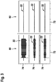
- FIG. 3 schematically shows a time course of the sensor signal 22 of an acceleration sensor 16 to the pump 54.
- the ordinate axes 74, 76 and 78 respectively depict the x, y and z components of the sensor signal 22 that fluctuate about zero with respect to a Cartesian coordinate system.
- state 80 the sensor signal 22 of the acceleration sensor 16 is shown in the normal operating state of the pump 54.
- State 82 illustrates sensor signal 22 at a defective pump 54.
- all components of sensor signal 22 are significantly lower than state 80 Maximum values and average values.
- average value is to be understood as meaning an amount of the sensor signal 22 averaged over a period of time.
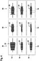
- FIG. 4 shows the schematic time course of the sensor signal 22 of an acceleration sensor 16 on the line 50 for water.
- the abscissa axes 72 each time is shown.
- the ordinate axes 74, 76 and 78 respectively represent the x, y and z components of the sensor signal 22 with respect to a Cartesian coordinate system.
- state 84 the sensor signal 22 of the acceleration sensor 16 is shown in the normal operating state.
- State 86 illustrates the course of the sensor signal 22 at a beginning loss of water. In this case, all components of the sensor signal 22 have lower maximum values and average values compared to the state 80.
- state 88 the sensor signals 22 are imaged at a critical loss of water. In this state 88, all components of the sensor signal 22 have strong fluctuations.
- the error variable 26 is determined in step 24 from an error function, which depends on at least one sensor signal 22.
- the choice of the error function depends on the technical and physical properties of the heating system 12 and / or the air conditioning or running in the heating system 12 and / or in the air conditioning processes, especially in fault conditions.
- the error function associated with a microphone signal may be logarithmic be to take into account the human volume impression.
- the error function with at least one sensor signal 22 is strictly monotonically increasing or decreasing.
- the error variable 26 is derived from a deviation of the sensor signal 22 from a desired signal specification 48 in step 24.
- the signal may be in the time domain or, as in FIG. 2 illustrated method 10, are compared in the frequency domain. In this case, mean values over a time and / or frequency range can also be used.
- the desired signal input 48 can be determined experimentally, for example, for different operating states of the heating system 12.
- the operating parameters 40 are determined in step 38 as a function of at least one error variable 26 as well as dependent on further sensor signals 22 and the old operating parameters.
- "old operating parameters" are to be understood as the operating parameters used prior to the execution of the method 10. In this way, the operating state of the heating system 12 and / or the air conditioning system is taken into account in the selection of the new operating parameters 40.
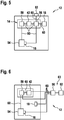
- the control unit 14 has a memory 42, a correction unit 56, a control unit 58 and an acceleration sensor 16 and a microphone 18.
- sensor signals 22 can be determined in step 20.
- the sensor signals 22 can be transmitted to the correction unit 56 via a communication connection 60.
- the correction unit 56 is set up such that the error signal 26 from the sensor signals 22 can be determined.
- the correction unit 56 is set up so that the step 30 can be executed so that a faulty state can be detected.
- the operating parameters 40 can be determined with the correction unit 56, depending on at least one error variable 26.
- the correction unit 56 has a communication connection 60 to a display unit 62, on which an error message 33 can be displayed.
- this is a TFT display with an associated control, by means of which the error indication signal of the correction unit 56 can be converted into a user-readable display display.
- the correction unit 56 has a communication connection 60 to the memory 42, so that the operating parameters 40 can be stored.
- the control unit 58 is set up so that components of the heating system 12 can be controlled.
- the control unit 58 has a communication connection 60 to a pump 54.
- the direction of rotation and the power of the pump 54 can thus be set by the transmission of control signals by the control unit 58.
- the acceleration sensor 16 is adhered to the pump 54.
- the adhesive used transmits vibrations.
- FIG. 6 shows a variant of the control unit 14 in the heating system 12.
- the correction unit 56 and the display unit 62 are designed to be mobile. Both elements of the control unit 14 are integrated in a portable diagnostic device 63, which can be used for diagnostic purposes.
- the communication links 60 between the correction unit 56 and the non-mobile parts of the control unit 14 are wireless Radio links, in this embodiment, are the connections via Zigbee. In alternative embodiments, WLAN, Bluetooth or Zwave is used.
- the correction unit 56 has a communication connection 60 to the control unit 58. In this way, step 34 is executable.
- At least one acceleration sensor 16 and / or at least one microphone 18 are also designed to be mobile. These may be present in a device with the mobile part of the control unit 14 or separately. To carry out a diagnosis then at least one acceleration sensor 16 and / or at least one microphone 18 in the heating system 12 are designed attachable. So they can be attached to designated components, preferably reversible, for example by clipping or screwing.
- At least one acceleration sensor 16 and / or one microphone 18 are permanently installed in a portable diagnostic device 63 together with the mobile parts of the control unit 14.
- the heating system 12 and / or the air conditioning system has or have a receptacle 64 suitable for the diagnostic device 63.
- FIG. 7 shows a variant of the heating system 12 with such a receptacle 64.
- the position of the receptacle 64 is selected so that the mobile acceleration sensor 16 can be attached by attaching the mobile diagnostic device 63 in the receptacle 64 on the pump 54.
- the receptacle 64 also has an interface that allows the communication link 60 between the mobile correction unit 56 and the non-mobile control unit 58.
- the correction unit 56 and / or the control unit 58 and / or the memory 42 may be partially or entirely in the form of software, which may be on internal or external devices, in particular mobile computing units, such as smartphones and tablets, or servers, in particular a cloud is running.
- the communication links 60 are then corresponding software interfaces.
- the control unit 14 or parts of the control unit 14 are provided by a mobile computing unit, in particular a smartphone or tablet.
- the portable diagnostic device 63 has at least one acceleration sensor 16 and / or a microphone 18 and a connection for a mobile computing unit, in particular a smartphone or tablet.
- the connection is intended for a communication connection 60 to the mobile computing unit.
- the communication link 60 between the mobile computing unit and the portable diagnostic device may be a wired connection or a wireless connection, in particular Bluetooth or WLAN. It is also conceivable that the mobile computing unit can be inserted into or connected to the portable diagnostic device 63, for example by a holder provided on the diagnostic device 63.
- the mobile computing unit receives data from the at least one acceleration sensor 16 and / or microphone 18 Computing unit provides the remaining mobile parts of the control unit 14, in particular the correction unit 56 and / or the control unit 58 and / or the memory 42, in particular wholly or partly in the form of software.
- the mobile computing unit can provide a display unit 62 and / or an input unit for user inputs, for example a touchscreen.
- At least one acceleration sensor 16 and / or microphone 18 of a mobile computing unit are used for the method 10.
- the mobile computing unit has the mobile parts of the control unit 14.
- the mobile computing unit has the at least one acceleration sensor 16 and / or microphone 18, the remaining mobile parts of the control unit can be completely or partially in the form of software.
- the receptacle 64 is adapted to receive the mobile computing unit.
- a heater 66 is shown as a realization of a heating system 12.
- an acceleration sensor 16 is attached to the pump 54, to the fan 44, to a heating cell 68, to the housing 70, to a line 50, to a valve 52 and to the control unit 14.
- the outside of the housing 70 has a microphone 18.
Landscapes
- Engineering & Computer Science (AREA)
- Mechanical Engineering (AREA)
- Physics & Mathematics (AREA)
- Thermal Sciences (AREA)
- Chemical & Material Sciences (AREA)
- Combustion & Propulsion (AREA)
- General Engineering & Computer Science (AREA)
- Air Conditioning Control Device (AREA)
Abstract
Description
- Die Erfindung betrifft ein Verfahren zur Detektion von Fehlzuständen in einem Heizsystem und/oder in einer Klimaanlage, insbesondere in einem HVAC System, mit einer Steuereinheit mit mindestens einem Beschleunigungssensor und/oder mindestens einem Mikrophon. Die Erfindung betrifft auch eine Steuereinheit, die zum Ausführen des erfindungsgemäßen Verfahrens ausgebildet ist sowie ein Heizsystem und/oder eine Klimaanlage mit der erfindungsgemäßen Steuereinheit.
- In handelsüblichen Heizsystemen werden zur Überwachung und Regelung des Betriebs Temperatur-, Druck- und gelegentlich Durchflusssensoren eingesetzt. Auf Basis der Sensordaten und interner Regeldaten können Fehlzustände detektiert und angezeigt werden. Allerdings ist diese Fehlererkennung begrenzt: Nicht alle Systemfehler können erkannt werden und die Bestimmung der Fehlerursache ist oft nicht eindeutig möglich.
- Das erfindungsgemäße Verfahren zur Detektion von Fehlzuständen in einem Heizsystem und/oder in einer Klimaanlage, insbesondere in einem HVAC System, mit den Merkmalen des Hauptanspruchs hat den Vorteil, dass dadurch, dass:
- mindestens ein Sensorsignal durch den mindestens einen Beschleunigungssensor und/oder das mindestens eine Mikrophon ermittelt wird,
- mindestens eine Fehlergröße basierend auf dem mindestens einen Sensorsignal ermittelt wird,
- ein Fehlzustand, falls die mindestens eine Fehlergröße einen zugehörigen Fehlerschwellenwert überschreitet, festgestellt wird,
- Dabei ist unter "Fehlzustand" ein Zustand des Heizsystems und/oder der Klimaanlage gemeint, in dem der Betrieb nicht im vorgesehen Rahmen möglich ist. Dazu gehören Defekte und Störungen sowie ein nicht optimaler Betrieb. Beispiele für Defekte und Störungen sind vollständig oder teilweise nicht funktionsfähige Pumpen und/oder Ventile, ein störendes Geräusch, beispielsweise ein Pfeifen, oder ein Wasserverlust bei einem Rohrbruch. Beispiele für einen nicht optimalen Betrieb sind eine Über- oder Unterbelastung des Heizsystems und/oder der Klimaanlage oder eine nicht optimale Verbrennung im Brennraum des Heizsystems, beispielsweise durch falsch eingestellte Betriebsparameter.
- Unter "Heizsystem" ist mindestens ein Gerät zur Erzeugung von Wärmeenergie, insbesondere ein Heizgerät bzw. Heizbrenner, insbesondere zur Verwendung in einer Gebäudeheizung und/oder zur Warmwassererzeugung, bevorzugt durch das Verbrennen von einem gasförmigen oder flüssigen Brennstoff zu verstehen. Ein Heizsystem kann auch mehrere solcher Geräte sowie weitere unterstützende Vorrichtungen, wie etwa Warmwasser- oder Brennstoffspeicher, aufweisen. Unter "Klimaanlage" ist mindestens ein Gerät zur Be- und/oder Entlüftung und/oder Sicherstellung der Luftzirkulation und/oder der Luftqualität und/oder ein Gerät zur Kühlung und/oder Feuchtigkeitskontrolle in einem Gebäude zu verstehen. Ein Heizsystem kann insbesondere auch zusammen mit einer Klimaanlage eingesetzt werden. Ein System, welches ein Heizsystem und eine Klimaanlage aufweist, wird auch als "Heating-Ventilation-Air-Conditioning System" oder kurz HVAC-System bezeichnet.
- Unter "Ermitteln eines Wertes" ist das unmittelbare Messen des Wertes, etwa durch einen entsprechenden Sensor, das Empfangen und/oder Verarbeiten von Informationen, welche direkte oder indirekte Rückschlüsse auf den Wert erlauben, sowie eine Kombination aus einen Messvorgang mit dem Empfang und/oder der Verarbeitung von Informationen zu verstehen.
- Durch die in den Unteransprüchen aufgeführten Merkmale sind vorteilhafte Weiterbildungen des Verfahrens nach dem Hauptanspruch möglich. Weist das Verfahren zur Detektion von Fehlzuständen einen zusätzlichen Schritt auf, in dem mindestens eine Fehlermeldung ausgegeben wird, falls ein Fehlzustand festgestellt wurde, erlaub dies, den Fehlzustand zu erkennen und gegebenfalls Gegenmaßnahmen einzuleiten. Beispielsweise kann eine Inspektion angefordert werden
- Wird in einem zusätzlichen Schritt mindestens ein auf der mindestens einen Fehlergröße basierendes Korrektursignal ermittelt, falls ein Fehlzustand festgestellt wurde, können automatisch Gegenmaßnahmen eingeleitet werden. Beispielsweise kann das Heizsystem und/oder die Klimaanlage heruntergefahren werden, um größere Schäden zu vermeiden.
- Dabei ist unter "Korrektursignal" mindestens ein Signal zum Ansteuern und/oder Einstellen des Betriebes von mindestens einer Komponente des Heizsystems und/oder der Klimaanlage zu verstehen. Beispielsweise kann das Korrektursignal ein Steuersignal an einen Lüfter sein, welches die Lüfterdrehzahl verändert.
- Werden in einem zusätzlichen Schritt Betriebsparameter, basierend auf der mindestens einen Fehlergröße, in der Steuereinheit in einem Speicher abgespeichert, erlaubt dies die gezielte Regelung des Heizsystems und/oder der Klimaanlage um dem Fehlzustand entgegenzuwirken. Insbesondere bei einer wiederholten, bevorzugt periodischen Ausführung des erfindungsgemäßen Verfahrens erlaubt das die iterative Behebung eines Fehlzustandes. Auf diese Weise kann der Betrieb des Heizsystems und/oder der Klimaanlage in einer Regelschleife optimiert werden. Damit wird ein optimaler Betrieb auch unter veränderlichen inneren und äußeren Bedingungen gewährleistet, insbesondere bei Verschleißprozessen und wechselnden Umweltbedingungen.
- Unter "Betriebsparameter" sind dabei Parameter zu verstehen, die von der Steuerung des Heizsystems und/oder der Klimaanlage zum Regeln und Überwachen von im Heizsystem und/oder in der Klimaanlage ablaufenden Prozessen verwendet werden. Beispiele für Betriebsparameter sind die Gebläsedrehzahl bzw. die Gebläsedrehzahlkennlinie oder eine Flammenionisationskennlinie.
- Wird die mindestens eine Fehlergröße von einem Maß für die Abweichung von dem mindestens einen Sensorsignal von einer zugehörigen Sollsignalvorgabe abgeleitet, erlaubt dies, das Verfahren auf bestimmte, den Fehlzustand auslösende Ereignisse einzustellen. So können beispielsweise in Simulationen oder Tests ermittelte, typische Signalverhalten bei Fehlern und/oder im optimalen Betrieb definiert werden. Diese typischen Signalverhalten können zur Detektion von Fehlzuständen eingesetzt werden. Ein Beispiel dafür ist eine Schwelle für ein Mikrophonsignal und seine zeitliche Entwicklung um sicherzustellen, dass die Geräuschbelastung nicht zu groß ist bzw. wird. Ein anderes Beispiel ist eine Frequenzanalyse von einem an einer Pumpe angebrachten Beschleunigungssensor um festzustellen, ob die Pumpe gleichmäßig und/oder im richtigen Drehsinn und/oder zu den richtigen Zeiten läuft.
- Die Verwendung einer Steuereinheit für ein Heizsystem und/oder eine Klimaanlage, die dafür eingerichtet ist das erfindungsgemäße Verfahren auszuführen, hat den Vorteil, dass auf diese Weise neben Defekten und Störungen auch ein nicht optimaler Betrieb des Heizsystems und oder der Klimaanlage erkennbar ist. Auf diese Weise wird die Effizienz und Haltbarkeit des Heizsystems und/oder der Klimaanlage gewährleistet.
- Ist die Steuereinheit oder sind Teile davon mobil ausgestaltet, kann das Verfahren zur Detektion von Fehlzuständen in unterschiedlichen Heizsystemen und/oder Klimaanlagen eingesetzt werden. Beispielsweise können die mobile Steuereinheit bzw. die mobilen Teile der Steuereinheit eine kompakte Funktionseinheit zur Detektion von Fehlzuständen bilden, welche einfach und problemlos bei Inspektionen von Heizsystem und/oder Klimaanlagen einsetzbar ist. Zusätzlich ist auf diese Weise die Verwendung der mobilen Steuereinheit bzw. von ihren mobilen Teilen zur Detektion von Fehlzuständen bei separaten, räumlich getrennten Komponenten eines Heizsystems und/oder einer Klimaanlage möglich. Weiterhin sind so die empfindlichen Teile der Steuereinheit von den in einem Heizsystem auftretenden thermischen und mechanischen Belastungen geschützt.
- Weist die Steuereinheit mindestens eine Kommunikationsverbindung, bevorzugt eine drahtlose Kommunikationsverbindung, zwischen den Teilen der Steuereinheit, bevorzugt zwischen den mobilen und nicht mobilen Teilen der Steuereinheit, auf, erlaubt das einen besonders einfachen und sicheren Ablauf des Verfahrens zur Detektion von Fehlzuständen. Die Betriebssicherheit ist erhöht, da Fehler durch eine falsche oder fehlende Kommunikationsverbindung vermieden werden. Besonders vorteilhaft ist das, wenn das mindestens eine Sensorsignal von im Heizsystem und/oder in der Klimaanlage fest verbauten Sensoren stammt, zu denen eine Kommunikationsverbindung mit der mobilen Steuereinheit hergestellt werden muss.
- Ein Heizsystem und/oder eine Klimaanlage mit einer erfindungsgemäßen Steuereinheit hat bzw. haben den Vorteil, dass Störungen in unterschiedlichen Betriebszuständen des Heizsystems und/oder der Klimaanlage erkannt werden. Das ist im Stand der Technik im Rahmen einer Inspektion nicht immer möglich, beispielsweise wenn Störungen nur unter bestimmten Betriebszuständen auftreten, die in der Regel während einer Inspektion aus Zeitgründen nicht untersucht werden, oder unter bestimmten äußeren Bedingungen auftreten, die während der Inspektion nicht gegeben sind.
- Weist das erfindungsgemäße Heizsystem und/oder die erfindungsgemäße Klimaanlage eine für die Steuereinheit oder für Teile der Steuereinheit vorgesehene Aufnahme auf, ermöglicht das einen besonders problemlosen Einsatz einer mobilen Steuereinheit bzw. von den mobilen Teilen einer Steuereinheit, etwa im Rahmen einer Inspektion. Zusätzlich ist so eine einfache Aufrüstung bzw. Erweiterung des Heizsystems und/oder der Klimaanlage durch das Nachrüsten mit der Steuereinheit bzw. Teilen der Steuereinheit möglich.
- Weist das Heizsystem und/oder die Klimaanlage mindestens eine Pumpe, ein Gebläse, eine Heizzelle, ein Gehäuse, ein Ventil, eine Leitung oder eine Steuereinheit auf und weist mindestens eine dieser Komponenten mindestens einen Beschleunigungssensor und/ oder ein Mikrophon auf, so hat das den Vorteil, dass die mindestens einen Beschleunigungssensor und/oder ein Mikrophon aufweisende Komponente besonders zuverlässig überwacht wird. Bei einem auftretenden Fehlzustand ist das Sensorsignal eindeutig der Komponente zugeordnet. Das ermöglicht eine besonders zielgerichtete und eindeutige Auswertung des Fehlzustandes.
- Ein Computerprogramm, umfassend Befehle, die bei der Ausführung des Programms durch einen Computer, insbesondere durch eine mobile Recheneinheit, diesen veranlassen, wenigstens einen Schritt des Verfahrens gemäß der vorliegenden Erfindung auszuführen, hat den Vorteil, dass das Verfahren teilweise insbesondere auf dezentralen Rechner durchgeführt werden kann, beispielsweise auf einer Cloud oder auf einem Smartphone. Das steigert den Benutzerkomfort und erlaubt, falls notwendig, eine besonders gründliche und umfassende Datenauswertung, welche beispielsweise auf einer lokalen Steuereinheit des Heizsystems in dem Umfang nicht möglich wäre.
- Es ist von Vorteil, wenn das Computerprogramm gemäß der vorliegenden Erfindung auf einem computerlesbaren Datenträger gespeichert ist.
- In den Zeichnungen sind Ausführungsbeispiele des erfindungsgemäßen Verfahrens zur Detektion von Fehlzuständen in einem Heizsystem und/oder in einer Klimaanlage, der erfindungsgemäßen Steuereinheit und des erfindungsgemäßen Heizsystems dargestellt und in der nachfolgenden Beschreibung näher erläutert. Es zeigen
-
Figur 1 das erfindungsgemäße Verfahren zur Detektion von Fehlzuständen in einem Heizsystem und/oder in einer Klimaanlage, -
Figur 2 eine Variante des erfindungsgemäßen Verfahrens, -
Figuren 3 und4 schematische Schaubilder von Sensorsignalen von Beschleunigungssensoren, -
Figur 5 eine schematische Darstellung der erfindungsgemäßen Steuereinheit in einem erfindungsgemäßen Heizsystem, -
Figuren 6 und7 schematische Darstellungen von Varianten der erfindungsgemäßen Steuereinheit in einem erfindungsgemäßen Heizsystem und -
Figur 8 eine Darstellung einer Variante des erfindungsgemäßen Heizsystems. - In den verschiedenen Ausführungsvarianten erhalten gleiche Teile bzw. Schritte die gleichen Bezugszahlen.
- In
Figur 1 ist das erfindungsgemäße Verfahren 10 zur Detektion von Fehlzuständen in einem Heizsystem 12 (sieheFigur 5 ) und/oder einer Klimaanlage mit einer Steuereinheit 14 mit einem Beschleunigungssensor 16 und einem Mikrophon 18 dargestellt. Im Ausführungsbeispiel wird in einem Schritt 20 jeweils ein Sensorsignal 22 von dem Beschleunigungssensor 16 und dem Mikrophon 18 empfangen und in einem Schritt 24 wird durch die Steuereinheit 14 abhängig vom Sensorsignal 22 eine Fehlergröße 26 ermittelt. Die Fehlergröße 26 wird mit einer Fehlerfunktion bestimmt, welche dem Sensorsignal 22 eine Fehlergröße 26 zuordnet. Dabei ist die dem Sensorsignal 22 des Mikrophons 18 zugeordnete Fehlergröße 26 proportional zu dem über eine definierte Messperiode auftretenden maximalen Schallpegel. Die dem Sensorsignal 22 des Beschleunigungssensors 16 zugeordnete Fehlergröße 26 ist proportional zu dem über die Messperiode gemittelten quadratischen Beschleunigungswert. Überschreitet die Fehlergröße 26 einen Fehlerschwellenwert 28, wird in einem Schritt 30 ein Fehlzustand festgestellt. Der Fehlerschwellenwert 28 wird empirisch ermittelt und ist in einem Speicher 42 abgelegt. - Wird in Schritt 30 ein Fehlzustand festgestellt, so wird das Verfahren 10 über den Pfad A fortgesetzt (siehe
Figur 1 ). Wird kein Fehlzustand festgestellt, wird das Verfahren 10 über den Pfad B beendet. Wird das Verfahren 10 über den Pfad A fortgesetzt, so werden die Schritte 32 und 34 ausgeführt. In Schritt 32 wird eine Fehlermeldung 33 auf einer Anzeigeeinheit 62 ausgegeben. Im Ausführungsbeispiel wird im Rahmen der Fehlermeldung 33 neben der Fehlergröße 26, dem die Fehlergröße 26 ermittelnden Sensor und dem Fehlerzeitpunkt auch die Kontaktinformationen zu einem für die Fehlerbehebung autorisierten Servicepartner angezeigt. - In Schritt 34 wird durch die Steuereinheit 14 ein Korrektursignal 36 an das Heizsystem 12 gesendet. Der Schritt 34 wird ausgeführt, falls die dem Beschleunigungssensor 16 zugeordnete Fehlergröße 26 den zugehörigen Fehlerschwellenwert 28 übersteigt. Im Ausführungsbeispiel ist das Korrektursignal 36 ein Shutdown Signal an alle Komponenten des Heizsystems 12. Das Heizsystem 12 wird heruntergefahren, um Schäden durch die auftretenden, zu starken Beschleunigungen zu verhindern.
-
Figur 2 zeigt eine alternative Ausführungsform des Verfahrens 10. Hier wird nach dem Schritt 30 ein Schritt 38 ausgeführt. In diesem Schritt 38 werden basierend auf der Fehlergröße 26 Betriebsparameter 40 in einem Speicher 42 der Steuereinheit 14 gespeichert. In dieser Ausführungsform wird ein Gebläse 44 (sieheFigur 8 ) mit einem Mikrophon 18 abgehört. Das Frequenzenspektrum des Sensorsignals 22 des Mikrophons 18 wird in Schritt 24 durch die Steuereinheit 14 mit einer Fourier-Analyse untersucht. Auf diese Weise lässt sich feststellen, ob das Gebläse 44 im richtigen Drehzahlbereich läuft. Es können auch mögliche Lagerschäden oder Unwuchten detektiert werden. Das Maß für eine Fehlergröße 26 wird über die Abweichung des Frequenzspektrums des Sensorsignals 22 des Mikrophons 18 von dem Frequenzspektrum einer Sollsignalvorgabe 48 definiert, wobei unerwünschte Resonanzfrequenzen des Heizsystems 12 besonders stark gewichtet sind. Der Fehlerschwellenwert 28 für das dem Gebläse 44 zugeordnete Sensorsignal 22 beschreibt einen noch hinreichend guten Betrieb des Gebläses 44 und hängt vom Betriebsmodus des Heizsystems 12 ab, zum Beispiel von der angeforderten Leistung. - Wird in Schritt 30 (in
Figur 2 ) kein Fehlzustand festgestellt, wird das Verfahren 10 über den Pfad B fortgesetzt. In diesem Fall wird Schritt 38 ausgeführt. Hier werden von der Fehlergröße 26 abhängige Betriebsparameter 40 in der Steuereinheit 14 gespeichert. In dieser Ausführungsform beschreiben die Betriebsparameter 40 die Gebläsedrehzahlkennlinie. Die Gebläsedrehzahlkennline beschreibt den Zusammenhang zwischen der benötigten Gebläsedrehzahl und der dafür nötigen Ansteuerspannung. Auf Basis dieser Betriebsparameter 40 wird das Gebläse 44 so angesteuert, dass die Gebläsedrehzahl, falls notwendig, zu einer optimalen Gebläsedrehzahl hin geändert wird. Das wiederholte Ausführen des Verfahrens 10 stellt eine Regelschleife dar. - Wird in Schritt 30 (in
Figur 2 ) ein Fehlzustand festgestellt, wird das Verfahren 10 über den Pfad A fortgesetzt. In diesem Fall werden die Schritte 38 und 32 ausgeführt. Hier wird durch die Ausgabe einer Fehlermeldung 33 eine Inspektion angefordert. - In alternativen, nicht gezeigten Verfahren 10 werden in Schritt 24 mehr als ein Sensorsignal 22 zu einer Fehlergröße 26 kombiniert. Beispielsweise können an einem Bauteil mehrere Beschleunigungssensoren 16 und/oder Mikrophone 18 angebracht sein. In anderen Ausführungen können Beschleunigungssensoren 16 und/oder Mikrophone 18 verschiedenen Komponenten eines HVAC Systems 12 zugeordnet sein und zu einer Fehlergröße 26 kombiniert werden. Auf diese Weise kann beispielsweise eine Gesamtgeräuschbelastung bewertet werden oder Fehlzustände erkannt werden, bei welchem mehr als eine Komponente beteiligt ist. Beispielsweise kann ein unruhiges, hakeliges Schaltverhalten eines Ventils 52 (siehe
Figur 8 ) an unerwünschten Vibrationen einer Leitung 50 (sieheFigur 8 ) erkannt werden.
In besonderen Varianten des Verfahrens 10 wird in Schritt 24 eine Fehlergröße 26 ermittelt, welche umgekehrt proportional zu dem Sensorsignal 22 ist. So wird ein Fehlzustand festgestellt, wenn mit dem Sensorsignal 22 zu niedrige Beschleunigungen und/oder Schallpegel erkannt werden. So lässt sich feststellen, ob bestimmte Bauteile und/oder Komponenten ordnungsgemäß funktionieren. Beispielsweise können zu niedrige Beschleunigungswerte an einer Pumpe 54 auf einen Defekt der Pumpe 54 hindeuten.Figur 3 zeigt schematisch einen Zeitverlauf des Sensorsignals 22 eines Beschleunigungssensors 16 an der Pumpe 54. Auf den Abszissenachsen 72 ist jeweils eine Zeit dargestellt. Auf den Ordinatenachsen 74, 76 und 78 sind jeweils die um Null schwankende x-, y- und z-Komponente des Sensorsignals 22 bezüglich eines kartesischen Koordinatensystems abgebildet. Im Zustand 80 ist das Sensorsignal 22 des Beschleunigungssensors 16 in normalen Betriebszustand der Pumpe 54 dargestellt. Zustand 82 veranschaulicht das Sensorsignal 22 bei einer defekten Pumpe 54. In diesem Fall weisen sämtliche Komponenten des Sensorsignals 22 im Vergleich zum Zustand 80 deutlich niedrigere Maximalwerte und Durchschnittswerte auf. Dabei ist an dieser Stelle unter "Durchschnittswert" ein über eine Zeit gemittelter Betrag des Sensorsignals 22 zu verstehen. - Ein anderes Beispiel ist die Verwendung von mindestens einem Beschleunigungssensor 16 an Leitungen 50 für Wasser, wo sinkende Beschleunigungswerte und/oder niedrige Beschleunigungswerte in Kombination mit anderen Sensorsignalen 22 einen Wasserverlust beschreiben.
Figur 4 zeigt den schematischen Zeitverlauf des Sensorsignals 22 eines Beschleunigungssensors 16 an der Leitung 50 für Wasser. Auf den Abszissenachsen 72 ist jeweils eine Zeit dargestellt. Auf den Ordinatenachsen 74, 76 und 78 sind jeweils die x-, y- und z-Komponente des Sensorsignals 22 bezüglich eines kartesischen Koordinatensystems abgebildet. Im Zustand 84 ist das Sensorsignal 22 des Beschleunigungssensors 16 in normalen Betriebszustand dargestellt. Zustand 86 veranschaulicht den Verlauf des Sensorsignals 22 bei einem beginnenden Wasserverlust. In diesem Fall weisen sämtliche Komponenten des Sensorsignals 22 im Vergleich zum Zustand 80 niedrigere Maximalwerte und Durchschnittswerte auf. Im Zustand 88 sind die Sensorsignale 22 bei einem kritischen Wasserverlust abgebildet. In diesem Zustand 88 weisen alle Komponenten des Sensorsignals 22 starke Schwankungen auf. - In anderen Varianten wird in Schritt 24 die Fehlergröße 26 aus einer Fehlerfunktion ermittelt, welche von mindestens einem Sensorsignal 22 abhängt. Die Wahl der Fehlerfunktion richtet sich nach den technischen und physikalischen Eigenschaften des Heizsystems 12 und/oder der Klimaanlage bzw. der im Heizsystem 12 und/oder in der Klimaanlage ablaufenden Prozesse, insbesondere bei Fehlzuständen. Beispielsweise kann die einem Mikrophonsignal zugeordnete Fehlerfunktion logarithmisch sein, um den menschlichen Lautstärkeeindruck zu berücksichtigen. Bevorzugt ist die Fehlerfunktion mit mindestens einem Sensorsignal 22 streng monoton steigen oder fallend.
- In weiteren Varianten wird in Schritt 24 die Fehlergröße 26 aus einer Abweichung des Sensorsignals 22 von einer Sollsignalvorgabe 48 abgeleitet. Dabei kann das Signal im Zeitbereich oder, wie im in
Figur 2 abgebildeten Verfahren 10, im Frequenzbereich verglichen werden. Dabei können auch Mittelwerte über einen Zeit- und/oder Frequenzbereich verwendet werden. Die Sollsignalvorgabe 48 kann beispielsweise experimentell für verschiedene Betriebszustände des Heizsystems 12 ermittelt werden. - In weiteren Varianten werden die Betriebsparameter 40 in Schritt 38 in abhängig von mindestens einer Fehlergröße 26 sowie abhängig von weiteren Sensorsignalen 22 und den alten Betriebsparametern ermittelt. Dabei sind unter "alte Betriebsparameter" die vor der Durchführung des Verfahrens 10 verwendeten Betriebsparameter zu verstehen. Auf diese Weise wird bei der Wahl der neuen Betriebsparameter 40 der Betriebszustand des Heizsystems 12 und/oder der Klimaanlage berücksichtigt.
-
Figur 5 zeigt das Ausführungsbeispiel der Steuereinheit 14 im Heizsystem 12. Die Steuereinheit 14 weist einen Speicher 42, eine Korrektureinheit 56, eine Regeleinheit 58 sowie einen Beschleunigungssensor 16 und ein Mikrophon 18 auf. Durch den Beschleunigungssensor 16 und das Mikrophon 18 sind in Schritt 20 Sensorsignale 22 ermittelbar. Die Sensorsignale 22 sind über eine Kommunikationsverbindung 60 an die Korrektureinheit 56 übermittelbar. Die Korrektureinheit 56 ist so eingerichtet, dass aus den Sensorsignalen 22 die Fehlergröße 26 ermittelbar ist. Weiterhin ist die Korrektureinheit 56 so eingerichtet, dass der Schritt 30 ausführbar ist, so dass ein Fehlzustand feststellbar ist. Weiterhin sind mit der Korrektureinheit 56 die Betriebsparameter 40 ermittelbar, abhängig von mindestens einer Fehlergröße 26. - Die Korrektureinheit 56 weist eine Kommunikationsverbindung 60 zu einer Anzeigeeinheit 62 auf, auf der eine Fehlermeldung 33 anzeigbar ist. Im Ausführungsbeispiel ist das ein TFT Display mit einer dazugehörigen Steuerung, durch welche das Fehleranzeigesignal der Korrektureinheit 56 in eine von einem Benutzer ablesbare Displayanzeige umsetzbar ist.
- Die Korrektureinheit 56 weist eine Kommunikationsverbindung 60 zum Speicher 42 auf, so dass die Betriebsparameter 40 abspeicherbar sind.
- Die Regeleinheit 58 ist so eingerichtet, dass Komponenten des Heizsystems 12 ansteuerbar sind. Dazu weist die Regeleinheit 58 eine Kommunikationsverbindung 60 zu einer Pumpe 54 auf. Im Ausführungsbeispiel ist so der Umlaufsinn und die Leistung der Pumpe 54 durch das Versenden von Steuersignalen durch die Regeleinheit 58 einstellbar.
- Der Beschleunigungssensor 16 ist an die Pumpe 54 angeklebt. Der dazu eingesetzte Kleber überträgt Vibrationen.
-
Figur 6 zeigt eine Variante der Steuereinheit 14 im Heizsystem 12. Hier sind die Korrektureinheit 56 und die Anzeigeeinheit 62 mobil ausgeführt. Beide Elemente der Steuereinheit 14 sind in einem tragbaren Diagnosegerät 63 integriert, welches für Diagnosezwecke einsetzbar ist. Die Kommunikationsverbindungen 60 zwischen der Korrektureinheit 56 und den nicht mobilen Teilen der Steuereinheit 14 sind drahtlose Funkverbindungen, in dieser Ausführungsform sind das Verbindungen über Zigbee. In alternativen Ausführungsformen wird WLAN, Bluetooth oder Zwave eingesetzt. Weiterhin weist die Korrektureinheit 56 eine Kommunikationsverbindung 60 zu der Regeleinheit 58 auf. Auf diese Weise ist der Schritt 34 ausführbar. - In besonderen Ausführungen sind auch mindestens ein Beschleunigungssensor 16 und/oder mindestens ein Mikrophon 18 mobil ausgeführt. Diese können in einem Gerät mit dem mobilen Teil der Steuereinheit 14 oder separat davon vorliegen. Zur Durchführung einer Diagnose sind dann mindestens ein Beschleunigungssensor 16 und/oder mindestens ein Mikrophon 18 im Heizsystem 12 anbringbar ausgestaltet. So können diese an dafür vorgesehene Komponenten angebracht werden, bevorzugt reversibel, beispielsweise durch Anclipsen oder Anschrauben.
- In anderen Varianten sind mindestens ein Beschleunigungssensor 16 und/oder ein Mikrophon 18 fest in einem tragbaren Diagnosegerät 63 zusammen mit den mobilen Teilen der Steuereinheit 14 eingebaut. Das ist besonders vorteilhaft, wenn das Heizsystem 12 und/oder die Klimaanlage eine für das Diagnosegerät 63 passende Aufnahme 64 aufweist bzw. aufweisen. In
Figur 7 zeigt eine Variante des Heizsystems 12 mit einer solchen Aufnahme 64. Die Position der Aufnahme 64 ist dabei so gewählt, dass der mobile Beschleunigungssensor 16 durch das Anbringen des mobilen Diagnosegeräts 63 in die Aufnahme 64 an der Pumpe 54 anbringbar ist. Die Aufnahme 64 weist auch eine Schnittstelle auf, die die Kommunikationsverbindung 60 zwischen der mobilen Korrektureinheit 56 und der nicht mobilen Regeleinheit 58 ermöglicht. - In alternativen Ausführungen können die Korrektureinheit 56 und/oder die Regeleinheit 58 und/oder der Speicher 42 teilweise oder ganz in der Form von Software vorliegen, die auf internen oder externen Geräten, insbesondere auf mobilen Recheneinheiten, beispielsweise Smartphones und Tablets, oder Servern, insbesondere einer Cloud, ausgeführt wird. Die Kommunikationsverbindungen 60 sind dann entsprechende Softwareschnittstellen. Insbesondere ist es denkbar, dass die Steuereinheit 14 bzw. Teile der Steuereinheit 14 von einer mobilen Recheneinheit, insbesondere einem Smartphone oder Tablet bereitgestellt werden.
- In besonderen Ausführungsformen weist das tragbare Diagnosegerät 63 mindestens einen Beschleunigungssensor 16 und/oder ein Mikrophon 18 sowie einen Anschluss für eine mobile Recheneinheit, insbesondere ein Smartphone oder Tablet. Der Anschluss ist für eine Kommunikationsverbindung 60 zur mobilen Recheneinheit vorgesehen. Die Kommunikationsverbindung 60 zwischen der mobilen Recheneinheit und dem tragbaren Diagnosegerät kann eine Kabelverbindung oder eine drahtlose Verbindung sein, insbesondere Bluetooth oder WLAN. Es ist auch denkbar, dass die mobile Recheneinheit in das tragbare Diagnosegerät 63 einlegbar bzw. mit diesem Verbindbar ist, beispielsweise durch eine dafür vorgesehene Halterung am Diagnosegerät 63. Die mobile Recheneinheit empfängt Daten vom mindestens einen Beschleunigungssensor 16 und/oder Mikrophon 18. Die mobile Recheneinheit stellt die übrigen mobilen Teile der Steuereinheit 14 bereit, insbesondere die Korrektureinheit 56 und/oder die Regeleinheit 58 und/oder den Speicher 42, insbesondere ganz oder teilweise in der Form von Software. Insbesondere kann die mobile Recheneinheit eine Anzeigeeinheit 62 und/oder eine Eingabeeinheit für Nutzereingaben bereitstellen, beispielsweise einen Touchscreen.
- In besonderen Ausführungen wird mindestens ein Beschleunigungssensor 16 und/oder Mikrophon 18 einer mobilen Recheneinheit, insbesondere eines Smartphones oder Tablets, für das Verfahren 10 eingesetzt. Die mobile Recheneinheit weist die mobilen Teile der Steuereinheit 14 auf. Insbesondere weist die mobile Recheneinheit die den mindestens einen Beschleunigungssensor 16 und/oder Mikrophon 18 auf, die übrigen mobilen Teile der Steuereinheit können vollständig oder teilweise in der Form von Software vorliegen. Insbesondere ist es denkbar, dass die Aufnahme 64 zum Aufnehmen der mobilen Recheneinheit eingerichtet ist.
- In
Figur 8 ist ein Heizgerät 66 als Realisierung eines Heizsystems 12 dargestellt. Hier ist an der Pumpe 54, am Gebläse 44, an einer Heizzelle 68, am Gehäuse 70, an einer Leitung 50, an einem Ventil 52 und an der Steuereinheit 14 jeweils ein Beschleunigungssensor 16 angebracht. Weiterhin weist die Außenseite des Gehäuses 70 ein Mikrophon 18 auf. Damit kann die Gesamtlärmbelastung analysiert werden.
Claims (13)
- Verfahren (10) zur Detektion von Fehlzuständen in einem Heizsystem (12) und/oder in einer Klimaanlage, insbesondere in einem HVAC System, mit einer Steuereinheit (14) mit mindestens einem Beschleunigungssensor (16) und/oder mindestens einem Mikrophon (18), welches die folgenden Schritte umfasst:• Ermitteln von mindestens einem Sensorsignal (22) durch den mindestens einen Beschleunigungssensor (16) und/oder durch das mindestens eine Mikrophon (18),• Ermitteln mindestens einer Fehlergröße (26) basierend auf dem mindestens einen Sensorsignal (22),• Feststellung eines Fehlzustandes, falls die mindestens eine Fehlergröße (26) einen zugehörigen Fehlerschwellenwert (28) überschreitet.
- Verfahren (10) zur Detektion von Fehlzuständen nach Anspruch 1, dadurch gekennzeichnet, dass in einem zusätzlichen Schritt mindestens eine Fehlermeldung (33) ausgegeben wird, falls ein Fehlzustand festgestellt wird.
- Verfahren (10) zur Detektion von Fehlzuständen nach einem der vorhergehenden Ansprüche, dadurch gekennzeichnet, dass in einem zusätzlichen Schritt mindestens ein auf mindestens einer Fehlergröße (26) basierendes Korrektursignal (36) ermittelt wird, falls ein Fehlzustand festgestellt wurde.
- Verfahren (10) zur Detektion von Fehlzuständen nach Anspruch 3, dadurch gekennzeichnet, dass in einem zusätzlichen Schritt Betriebsparameter (40), basierend auf mindestens einer Fehlergröße (26), in der Steuereinheit (14) in einem Speicher (42) abgespeichert werden.
- Verfahren (10) zur Detektion von Fehlzuständen nach einem der vorhergehenden Ansprüche, dadurch gekennzeichnet, dass die mindestens eine Fehlergröße (26) von einem Maß für die Abweichung von dem mindestens einen Sensorsignal (22) von einer zugehörigen Sollsignalvorgabe (48) abgeleitet wird.
- Steuereinheit (14) für ein Heizsystem (12) und/oder für eine Klimaanlage, die dafür eingerichtet ist, ein Verfahren (10) nach einem der vorhergehenden Ansprüche auszuführen.
- Steuereinheit (14) für ein Heizsystem (12) und/oder für eine Klimaanlage nach Anspruch 6, dadurch gekennzeichnet, dass die Steuereinheit (14) oder Teile davon mobil ausgestaltet ist bzw. sind.
- Steuereinheit (14) für ein Heizsystem (12) und/oder für eine Klimaanlage nach Anspruch 6 oder 7, dadurch gekennzeichnet, dass die Steuereinheit (14) mindestens eine Kommunikationsverbindung (60), bevorzugt eine drahtlose Kommunikationsverbindung (60), zwischen den Teilen der Steuereinheit (14), bevorzugt zwischen den mobilen und nicht mobilen Teilen der Steuereinheit, (14) aufweist.
- Heizsystem (12) und/oder Klimaanlage, insbesondere ein HVAC System, mit einer Steuereinheit (14) nach einem der Ansprüche 6 bis 8.
- Heizsystem (12) und/oder Klimaanlage nach Anspruch 9, dadurch gekennzeichnet, dass das Heizsystem (12) und/oder die Klimaanlage eine für die Steuereinheit (14) oder für Teile der Steuereinheit (14) vorgesehene Aufnahme (64) aufweist.
- Heizsystem (12) und/oder Klimaanlage nach einem der Ansprüche 9 oder 10, dadurch gekennzeichnet, dass das Heizsystem (12) und/oder die Klimaanlage mindestens eine Pumpe (54), ein Gebläse (44), eine Heizzelle (68), ein Gehäuse (70), ein Ventil (52), eine Leitung (50) oder eine Steuereinheit (14) aufweist und mindestens eine dieser Komponenten mindestens einen Beschleunigungssensor (16) und/oder ein Mikrophon (18) aufweist.
- Computerprogramm, umfassend Befehle, die bei der Ausführung des Programms durch einen Computer, insbesondere durch eine mobile Recheneinheit, diesen veranlassen, wenigstens einen Schritt des Verfahrens (10) nach einem der Ansprüche 1 bis 5 auszuführen.
- Computerlesbarer Datenträger, auf dem das Computerprogramm nach Anspruch 12 gespeichert ist.
Applications Claiming Priority (1)
| Application Number | Priority Date | Filing Date | Title |
|---|---|---|---|
| DE102016210418.7A DE102016210418A1 (de) | 2016-06-13 | 2016-06-13 | Verfahren und Steuereinheit zur Detektion von Fehlzuständen in einem Heizsystem und/oder in einer Klimaanlage sowie ein Heizsystem und/oder eine Klimaanlage |
Publications (2)
| Publication Number | Publication Date |
|---|---|
| EP3258183A1 true EP3258183A1 (de) | 2017-12-20 |
| EP3258183B1 EP3258183B1 (de) | 2023-08-09 |
Family
ID=59034622
Family Applications (1)
| Application Number | Title | Priority Date | Filing Date |
|---|---|---|---|
| EP17175406.2A Active EP3258183B1 (de) | 2016-06-13 | 2017-06-12 | Verfahren und steuereinheit zur detektion von fehlzuständen in einem heizsystem und/oder in einer klimaanlage sowie ein heizsystem und/oder eine klimaanlage |
Country Status (2)
| Country | Link |
|---|---|
| EP (1) | EP3258183B1 (de) |
| DE (1) | DE102016210418A1 (de) |
Cited By (1)
| Publication number | Priority date | Publication date | Assignee | Title |
|---|---|---|---|---|
| CN117167901A (zh) * | 2023-08-28 | 2023-12-05 | 珠海格力节能环保制冷技术研究中心有限公司 | 故障处理方法、装置、风盘机组、设备、介质和程序产品 |
Families Citing this family (3)
| Publication number | Priority date | Publication date | Assignee | Title |
|---|---|---|---|---|
| CN113719889B (zh) * | 2021-09-09 | 2023-04-07 | 中国电子信息产业集团有限公司第六研究所 | 一种区块链边缘流量安全控制方法、系统、电子设备 |
| DE102023108842A1 (de) * | 2023-04-06 | 2024-10-10 | Vaillant Gmbh | Verfahren zur Minderung der Geräuschemissionen eines HVAC-Systems, Regel- und Steuergerät, HVAC-System und Computerprogramm |
| DE102024120393A1 (de) * | 2024-07-18 | 2026-01-22 | Vaillant Gmbh | Verfahren zum Betreiben eines HVAC-Systems, HVAC-System und Computerprogramm |
Citations (6)
| Publication number | Priority date | Publication date | Assignee | Title |
|---|---|---|---|---|
| US20030200014A1 (en) * | 2002-04-17 | 2003-10-23 | Remboski Donald J. | Synchronous sampling of rotating elements in a fault detection system having audio analysis and method of using the same |
| EP2518414A1 (de) * | 2009-12-25 | 2012-10-31 | Mitsubishi Electric Corporation | Klimaanlage |
| US20130037620A1 (en) * | 2011-08-12 | 2013-02-14 | Qualcomm Incorporated | Controlling air movers based on acoustic signature |
| US20130166051A1 (en) * | 2011-12-21 | 2013-06-27 | Lennox Industries, Inc. | Hvac unit with audio monitoring, a method of audio monitoring events of an hvac unit and a controller configured to perform the method of audio monitoring |
| CN103527445A (zh) * | 2013-08-30 | 2014-01-22 | 青岛海信日立空调系统有限公司 | 一种空调及其噪声消除方法 |
| CN104848432A (zh) * | 2015-05-29 | 2015-08-19 | 东南大学 | 一种带主动降噪装置的空气净化器 |
Family Cites Families (4)
| Publication number | Priority date | Publication date | Assignee | Title |
|---|---|---|---|---|
| KR101242375B1 (ko) * | 2010-10-27 | 2013-03-14 | 엘지전자 주식회사 | 공기조화장치 |
| JP5592240B2 (ja) * | 2010-11-30 | 2014-09-17 | リンナイ株式会社 | 温風暖房機 |
| JP5627504B2 (ja) * | 2011-02-22 | 2014-11-19 | 三菱電機株式会社 | 空調設備保守システム及びデータ解析装置 |
| CN202126056U (zh) * | 2011-07-14 | 2012-01-25 | Tcl空调器(中山)有限公司 | 变频空调器 |
-
2016
- 2016-06-13 DE DE102016210418.7A patent/DE102016210418A1/de active Pending
-
2017
- 2017-06-12 EP EP17175406.2A patent/EP3258183B1/de active Active
Patent Citations (6)
| Publication number | Priority date | Publication date | Assignee | Title |
|---|---|---|---|---|
| US20030200014A1 (en) * | 2002-04-17 | 2003-10-23 | Remboski Donald J. | Synchronous sampling of rotating elements in a fault detection system having audio analysis and method of using the same |
| EP2518414A1 (de) * | 2009-12-25 | 2012-10-31 | Mitsubishi Electric Corporation | Klimaanlage |
| US20130037620A1 (en) * | 2011-08-12 | 2013-02-14 | Qualcomm Incorporated | Controlling air movers based on acoustic signature |
| US20130166051A1 (en) * | 2011-12-21 | 2013-06-27 | Lennox Industries, Inc. | Hvac unit with audio monitoring, a method of audio monitoring events of an hvac unit and a controller configured to perform the method of audio monitoring |
| CN103527445A (zh) * | 2013-08-30 | 2014-01-22 | 青岛海信日立空调系统有限公司 | 一种空调及其噪声消除方法 |
| CN104848432A (zh) * | 2015-05-29 | 2015-08-19 | 东南大学 | 一种带主动降噪装置的空气净化器 |
Cited By (1)
| Publication number | Priority date | Publication date | Assignee | Title |
|---|---|---|---|---|
| CN117167901A (zh) * | 2023-08-28 | 2023-12-05 | 珠海格力节能环保制冷技术研究中心有限公司 | 故障处理方法、装置、风盘机组、设备、介质和程序产品 |
Also Published As
| Publication number | Publication date |
|---|---|
| EP3258183B1 (de) | 2023-08-09 |
| DE102016210418A1 (de) | 2017-12-14 |
Similar Documents
| Publication | Publication Date | Title |
|---|---|---|
| EP2697572B1 (de) | Automatisierte funktionsdiagnose | |
| EP3258183B1 (de) | Verfahren und steuereinheit zur detektion von fehlzuständen in einem heizsystem und/oder in einer klimaanlage sowie ein heizsystem und/oder eine klimaanlage | |
| EP2475920B1 (de) | Diagnosesystem für ein ventil | |
| DE102005003251B4 (de) | Verfahren zum Prüfen und zum Bestimmen der Irrationalität eines Motorkühltemperaturfühlers in einem Fahrzeug | |
| DE102017200855B4 (de) | Verfahren und System zur Diagnose eines Zustands eines Dämpfungssystems eines Fahrzeugs | |
| DE102007010768B4 (de) | Verfahren für die Optimierung der Ventilstellung und der Pumpendrehzahl in einem Ventilsystem mit PID-Regelung ohne die Verwendung externer Signale | |
| CN109654662B (zh) | 检测元件控制方法、装置及空调机组 | |
| DE102008058208B4 (de) | Stellgerät und Verfahren zur Überprüfung der korrekten Funktionsfähigkeit eines Faltenbalges eines Stellgerätes | |
| DE102016124035B4 (de) | Verfahren zum Diagnostizieren eines Ausfalls einer Leistungsstufe eines elektronischen Wastegateaktuators | |
| WO2024042017A1 (de) | System und verfahren zur überwachung einer anlage mit einer steuerbaren anlagenkomponente | |
| WO2021244869A1 (de) | Verfahren zum betrieb einer überwachungsvorrichtung zur überwachung einer heizungsanlage, überwachungsvorrichtung und heizungsanlage mit der überwachungsvorrichtung | |
| DE10254485B4 (de) | Kraftfahrzeug | |
| EP2045158B1 (de) | Druckluftversorgungseinrichtung mit Leckagenanalyse und Verfahren zum Betreiben einer solchen Druckluftversorgungseinrichtung | |
| EP3712502A1 (de) | Verfahren zum prüfen des vorhandenseins einer rückschlagklappe in einer heizungsanlage | |
| DE102019206784A1 (de) | Verfahren und Anordnung zur Zustandsbestimmung einer Batterievorrichtung | |
| WO2014161542A1 (de) | Verfahren zur automatisierten inbetriebnahme eines getriebes eines kraftfahrzeuges | |
| DE102020105066B4 (de) | Verfahren zum Betreiben einer Kontrollanzeigeeinrichtung, Wartungsüberwachungseinrichtung, Kraftfahrzeug, und Servervorrichtung | |
| WO2008128598A1 (de) | Verfahren zur diagnose von technischen systemen, insbesondere im kraftfahrzeugbereich | |
| EP4086526B1 (de) | Verfahren zur überwachung einer heizungsanlage, computerprogramm, regel- und steuergerät, heizungsanlage und verwendung von betriebsdaten einer heizungsanlage | |
| DE102007001452A1 (de) | Verfahren und Vorrichtung zur Ermittlung einer Kältemittelunterfüllung eines Kältemittelkreislaufs einer Klimaanlage für ein Fahrzeug | |
| US20240230140A1 (en) | An hvac system and related methods | |
| CN106227193A (zh) | 一种汽车故障诊断系统及其诊断方法 | |
| DE102016209450A1 (de) | Verfahren zur Überwachung einer Entlüftung eines Kurbelgehäuses | |
| DE102005031552B4 (de) | Verfahren zur Betriebsprüfung einer Messeinrichtung | |
| EP3433693B1 (de) | Verfahren und system zur überwachung einer basiseinrichtung durch ein mobiles endgerät |
Legal Events
| Date | Code | Title | Description |
|---|---|---|---|
| PUAI | Public reference made under article 153(3) epc to a published international application that has entered the european phase |
Free format text: ORIGINAL CODE: 0009012 |
|
| STAA | Information on the status of an ep patent application or granted ep patent |
Free format text: STATUS: THE APPLICATION HAS BEEN PUBLISHED |
|
| AK | Designated contracting states |
Kind code of ref document: A1 Designated state(s): AL AT BE BG CH CY CZ DE DK EE ES FI FR GB GR HR HU IE IS IT LI LT LU LV MC MK MT NL NO PL PT RO RS SE SI SK SM TR |
|
| AX | Request for extension of the european patent |
Extension state: BA ME |
|
| STAA | Information on the status of an ep patent application or granted ep patent |
Free format text: STATUS: REQUEST FOR EXAMINATION WAS MADE |
|
| 17P | Request for examination filed |
Effective date: 20180620 |
|
| RBV | Designated contracting states (corrected) |
Designated state(s): AL AT BE BG CH CY CZ DE DK EE ES FI FR GB GR HR HU IE IS IT LI LT LU LV MC MK MT NL NO PL PT RO RS SE SI SK SM TR |
|
| STAA | Information on the status of an ep patent application or granted ep patent |
Free format text: STATUS: EXAMINATION IS IN PROGRESS |
|
| RAP1 | Party data changed (applicant data changed or rights of an application transferred) |
Owner name: ROBERT BOSCH GMBH |
|
| 17Q | First examination report despatched |
Effective date: 20200421 |
|
| REG | Reference to a national code |
Ref country code: DE Ref legal event code: R079 Free format text: PREVIOUS MAIN CLASS: F24F0011000000 Ipc: F24F0011300000 Ref country code: DE Ref legal event code: R079 Ref document number: 502017015166 Country of ref document: DE Free format text: PREVIOUS MAIN CLASS: F24F0011000000 Ipc: F24F0011300000 |
|
| RIC1 | Information provided on ipc code assigned before grant |
Ipc: B60H 1/00 20060101ALI20221129BHEP Ipc: F24F 130/40 20180101ALI20221129BHEP Ipc: F24F 110/00 20180101ALI20221129BHEP Ipc: F24F 11/30 20180101AFI20221129BHEP |
|
| GRAP | Despatch of communication of intention to grant a patent |
Free format text: ORIGINAL CODE: EPIDOSNIGR1 |
|
| STAA | Information on the status of an ep patent application or granted ep patent |
Free format text: STATUS: GRANT OF PATENT IS INTENDED |
|
| INTG | Intention to grant announced |
Effective date: 20230309 |
|
| GRAS | Grant fee paid |
Free format text: ORIGINAL CODE: EPIDOSNIGR3 |
|
| GRAA | (expected) grant |
Free format text: ORIGINAL CODE: 0009210 |
|
| STAA | Information on the status of an ep patent application or granted ep patent |
Free format text: STATUS: THE PATENT HAS BEEN GRANTED |
|
| AK | Designated contracting states |
Kind code of ref document: B1 Designated state(s): AL AT BE BG CH CY CZ DE DK EE ES FI FR GB GR HR HU IE IS IT LI LT LU LV MC MK MT NL NO PL PT RO RS SE SI SK SM TR |
|
| REG | Reference to a national code |
Ref country code: GB Ref legal event code: FG4D Free format text: NOT ENGLISH |
|
| REG | Reference to a national code |
Ref country code: CH Ref legal event code: EP |
|
| REG | Reference to a national code |
Ref country code: IE Ref legal event code: FG4D Free format text: LANGUAGE OF EP DOCUMENT: GERMAN |
|
| REG | Reference to a national code |
Ref country code: DE Ref legal event code: R096 Ref document number: 502017015166 Country of ref document: DE |
|
| REG | Reference to a national code |
Ref country code: SE Ref legal event code: TRGR |
|
| REG | Reference to a national code |
Ref country code: NL Ref legal event code: FP |
|
| REG | Reference to a national code |
Ref country code: LT Ref legal event code: MG9D |
|
| PG25 | Lapsed in a contracting state [announced via postgrant information from national office to epo] |
Ref country code: GR Free format text: LAPSE BECAUSE OF FAILURE TO SUBMIT A TRANSLATION OF THE DESCRIPTION OR TO PAY THE FEE WITHIN THE PRESCRIBED TIME-LIMIT Effective date: 20231110 |
|
| PG25 | Lapsed in a contracting state [announced via postgrant information from national office to epo] |
Ref country code: IS Free format text: LAPSE BECAUSE OF FAILURE TO SUBMIT A TRANSLATION OF THE DESCRIPTION OR TO PAY THE FEE WITHIN THE PRESCRIBED TIME-LIMIT Effective date: 20231209 |
|
| PG25 | Lapsed in a contracting state [announced via postgrant information from national office to epo] |
Ref country code: RS Free format text: LAPSE BECAUSE OF FAILURE TO SUBMIT A TRANSLATION OF THE DESCRIPTION OR TO PAY THE FEE WITHIN THE PRESCRIBED TIME-LIMIT Effective date: 20230809 Ref country code: PT Free format text: LAPSE BECAUSE OF FAILURE TO SUBMIT A TRANSLATION OF THE DESCRIPTION OR TO PAY THE FEE WITHIN THE PRESCRIBED TIME-LIMIT Effective date: 20231211 Ref country code: NO Free format text: LAPSE BECAUSE OF FAILURE TO SUBMIT A TRANSLATION OF THE DESCRIPTION OR TO PAY THE FEE WITHIN THE PRESCRIBED TIME-LIMIT Effective date: 20231109 Ref country code: LV Free format text: LAPSE BECAUSE OF FAILURE TO SUBMIT A TRANSLATION OF THE DESCRIPTION OR TO PAY THE FEE WITHIN THE PRESCRIBED TIME-LIMIT Effective date: 20230809 Ref country code: LT Free format text: LAPSE BECAUSE OF FAILURE TO SUBMIT A TRANSLATION OF THE DESCRIPTION OR TO PAY THE FEE WITHIN THE PRESCRIBED TIME-LIMIT Effective date: 20230809 Ref country code: IS Free format text: LAPSE BECAUSE OF FAILURE TO SUBMIT A TRANSLATION OF THE DESCRIPTION OR TO PAY THE FEE WITHIN THE PRESCRIBED TIME-LIMIT Effective date: 20231209 Ref country code: HR Free format text: LAPSE BECAUSE OF FAILURE TO SUBMIT A TRANSLATION OF THE DESCRIPTION OR TO PAY THE FEE WITHIN THE PRESCRIBED TIME-LIMIT Effective date: 20230809 Ref country code: GR Free format text: LAPSE BECAUSE OF FAILURE TO SUBMIT A TRANSLATION OF THE DESCRIPTION OR TO PAY THE FEE WITHIN THE PRESCRIBED TIME-LIMIT Effective date: 20231110 Ref country code: FI Free format text: LAPSE BECAUSE OF FAILURE TO SUBMIT A TRANSLATION OF THE DESCRIPTION OR TO PAY THE FEE WITHIN THE PRESCRIBED TIME-LIMIT Effective date: 20230809 |
|
| PG25 | Lapsed in a contracting state [announced via postgrant information from national office to epo] |
Ref country code: PL Free format text: LAPSE BECAUSE OF FAILURE TO SUBMIT A TRANSLATION OF THE DESCRIPTION OR TO PAY THE FEE WITHIN THE PRESCRIBED TIME-LIMIT Effective date: 20230809 |
|
| PG25 | Lapsed in a contracting state [announced via postgrant information from national office to epo] |
Ref country code: ES Free format text: LAPSE BECAUSE OF FAILURE TO SUBMIT A TRANSLATION OF THE DESCRIPTION OR TO PAY THE FEE WITHIN THE PRESCRIBED TIME-LIMIT Effective date: 20230809 |
|
| PG25 | Lapsed in a contracting state [announced via postgrant information from national office to epo] |
Ref country code: SM Free format text: LAPSE BECAUSE OF FAILURE TO SUBMIT A TRANSLATION OF THE DESCRIPTION OR TO PAY THE FEE WITHIN THE PRESCRIBED TIME-LIMIT Effective date: 20230809 Ref country code: RO Free format text: LAPSE BECAUSE OF FAILURE TO SUBMIT A TRANSLATION OF THE DESCRIPTION OR TO PAY THE FEE WITHIN THE PRESCRIBED TIME-LIMIT Effective date: 20230809 Ref country code: ES Free format text: LAPSE BECAUSE OF FAILURE TO SUBMIT A TRANSLATION OF THE DESCRIPTION OR TO PAY THE FEE WITHIN THE PRESCRIBED TIME-LIMIT Effective date: 20230809 Ref country code: EE Free format text: LAPSE BECAUSE OF FAILURE TO SUBMIT A TRANSLATION OF THE DESCRIPTION OR TO PAY THE FEE WITHIN THE PRESCRIBED TIME-LIMIT Effective date: 20230809 Ref country code: DK Free format text: LAPSE BECAUSE OF FAILURE TO SUBMIT A TRANSLATION OF THE DESCRIPTION OR TO PAY THE FEE WITHIN THE PRESCRIBED TIME-LIMIT Effective date: 20230809 Ref country code: CZ Free format text: LAPSE BECAUSE OF FAILURE TO SUBMIT A TRANSLATION OF THE DESCRIPTION OR TO PAY THE FEE WITHIN THE PRESCRIBED TIME-LIMIT Effective date: 20230809 Ref country code: SK Free format text: LAPSE BECAUSE OF FAILURE TO SUBMIT A TRANSLATION OF THE DESCRIPTION OR TO PAY THE FEE WITHIN THE PRESCRIBED TIME-LIMIT Effective date: 20230809 |
|
| REG | Reference to a national code |
Ref country code: DE Ref legal event code: R097 Ref document number: 502017015166 Country of ref document: DE |
|
| PG25 | Lapsed in a contracting state [announced via postgrant information from national office to epo] |
Ref country code: IT Free format text: LAPSE BECAUSE OF FAILURE TO SUBMIT A TRANSLATION OF THE DESCRIPTION OR TO PAY THE FEE WITHIN THE PRESCRIBED TIME-LIMIT Effective date: 20230809 |
|
| PLBE | No opposition filed within time limit |
Free format text: ORIGINAL CODE: 0009261 |
|
| STAA | Information on the status of an ep patent application or granted ep patent |
Free format text: STATUS: NO OPPOSITION FILED WITHIN TIME LIMIT |
|
| 26N | No opposition filed |
Effective date: 20240513 |
|
| PG25 | Lapsed in a contracting state [announced via postgrant information from national office to epo] |
Ref country code: SI Free format text: LAPSE BECAUSE OF FAILURE TO SUBMIT A TRANSLATION OF THE DESCRIPTION OR TO PAY THE FEE WITHIN THE PRESCRIBED TIME-LIMIT Effective date: 20230809 |
|
| PG25 | Lapsed in a contracting state [announced via postgrant information from national office to epo] |
Ref country code: BG Free format text: LAPSE BECAUSE OF FAILURE TO SUBMIT A TRANSLATION OF THE DESCRIPTION OR TO PAY THE FEE WITHIN THE PRESCRIBED TIME-LIMIT Effective date: 20230809 |
|
| PG25 | Lapsed in a contracting state [announced via postgrant information from national office to epo] |
Ref country code: BG Free format text: LAPSE BECAUSE OF FAILURE TO SUBMIT A TRANSLATION OF THE DESCRIPTION OR TO PAY THE FEE WITHIN THE PRESCRIBED TIME-LIMIT Effective date: 20230809 |
|
| PG25 | Lapsed in a contracting state [announced via postgrant information from national office to epo] |
Ref country code: MC Free format text: LAPSE BECAUSE OF FAILURE TO SUBMIT A TRANSLATION OF THE DESCRIPTION OR TO PAY THE FEE WITHIN THE PRESCRIBED TIME-LIMIT Effective date: 20230809 |
|
| REG | Reference to a national code |
Ref country code: CH Ref legal event code: PL |
|
| PG25 | Lapsed in a contracting state [announced via postgrant information from national office to epo] |
Ref country code: LU Free format text: LAPSE BECAUSE OF NON-PAYMENT OF DUE FEES Effective date: 20240612 |
|
| PG25 | Lapsed in a contracting state [announced via postgrant information from national office to epo] |
Ref country code: IE Free format text: LAPSE BECAUSE OF NON-PAYMENT OF DUE FEES Effective date: 20240612 |
|
| PG25 | Lapsed in a contracting state [announced via postgrant information from national office to epo] |
Ref country code: BE Free format text: LAPSE BECAUSE OF NON-PAYMENT OF DUE FEES Effective date: 20240630 Ref country code: CH Free format text: LAPSE BECAUSE OF NON-PAYMENT OF DUE FEES Effective date: 20240630 |
|
| REG | Reference to a national code |
Ref country code: BE Ref legal event code: MM Effective date: 20240630 |
|
| PGFP | Annual fee paid to national office [announced via postgrant information from national office to epo] |
Ref country code: GB Payment date: 20250620 Year of fee payment: 9 |
|
| PGFP | Annual fee paid to national office [announced via postgrant information from national office to epo] |
Ref country code: NL Payment date: 20250618 Year of fee payment: 9 |
|
| PGFP | Annual fee paid to national office [announced via postgrant information from national office to epo] |
Ref country code: FR Payment date: 20250626 Year of fee payment: 9 |
|
| PGFP | Annual fee paid to national office [announced via postgrant information from national office to epo] |
Ref country code: SE Payment date: 20250618 Year of fee payment: 9 |
|
| REG | Reference to a national code |
Ref country code: AT Ref legal event code: MM01 Ref document number: 1597943 Country of ref document: AT Kind code of ref document: T Effective date: 20240612 |
|
| PGFP | Annual fee paid to national office [announced via postgrant information from national office to epo] |
Ref country code: DE Payment date: 20250814 Year of fee payment: 9 |
|
| PG25 | Lapsed in a contracting state [announced via postgrant information from national office to epo] |
Ref country code: AT Free format text: LAPSE BECAUSE OF NON-PAYMENT OF DUE FEES Effective date: 20240612 |
|
| PG25 | Lapsed in a contracting state [announced via postgrant information from national office to epo] |
Ref country code: CY Free format text: LAPSE BECAUSE OF FAILURE TO SUBMIT A TRANSLATION OF THE DESCRIPTION OR TO PAY THE FEE WITHIN THE PRESCRIBED TIME-LIMIT; INVALID AB INITIO Effective date: 20170612 |
|
| PG25 | Lapsed in a contracting state [announced via postgrant information from national office to epo] |
Ref country code: HU Free format text: LAPSE BECAUSE OF FAILURE TO SUBMIT A TRANSLATION OF THE DESCRIPTION OR TO PAY THE FEE WITHIN THE PRESCRIBED TIME-LIMIT; INVALID AB INITIO Effective date: 20170612 |