EP3257690A1 - Structure for bonding press-molded article, structural article for automobile having said bonding structure, and method for manufacturing bonded article - Google Patents
Structure for bonding press-molded article, structural article for automobile having said bonding structure, and method for manufacturing bonded article Download PDFInfo
- Publication number
- EP3257690A1 EP3257690A1 EP16749034.1A EP16749034A EP3257690A1 EP 3257690 A1 EP3257690 A1 EP 3257690A1 EP 16749034 A EP16749034 A EP 16749034A EP 3257690 A1 EP3257690 A1 EP 3257690A1
- Authority
- EP
- European Patent Office
- Prior art keywords
- welding
- forming
- press
- side part
- step portion
- Prior art date
- Legal status (The legal status is an assumption and is not a legal conclusion. Google has not performed a legal analysis and makes no representation as to the accuracy of the status listed.)
- Granted
Links
Images


Classifications
-
- B—PERFORMING OPERATIONS; TRANSPORTING
- B23—MACHINE TOOLS; METAL-WORKING NOT OTHERWISE PROVIDED FOR
- B23K—SOLDERING OR UNSOLDERING; WELDING; CLADDING OR PLATING BY SOLDERING OR WELDING; CUTTING BY APPLYING HEAT LOCALLY, e.g. FLAME CUTTING; WORKING BY LASER BEAM
- B23K9/00—Arc welding or cutting
- B23K9/02—Seam welding; Backing means; Inserts
- B23K9/025—Seam welding; Backing means; Inserts for rectilinear seams
-
- B—PERFORMING OPERATIONS; TRANSPORTING
- B23—MACHINE TOOLS; METAL-WORKING NOT OTHERWISE PROVIDED FOR
- B23K—SOLDERING OR UNSOLDERING; WELDING; CLADDING OR PLATING BY SOLDERING OR WELDING; CUTTING BY APPLYING HEAT LOCALLY, e.g. FLAME CUTTING; WORKING BY LASER BEAM
- B23K9/00—Arc welding or cutting
- B23K9/02—Seam welding; Backing means; Inserts
-
- B—PERFORMING OPERATIONS; TRANSPORTING
- B23—MACHINE TOOLS; METAL-WORKING NOT OTHERWISE PROVIDED FOR
- B23K—SOLDERING OR UNSOLDERING; WELDING; CLADDING OR PLATING BY SOLDERING OR WELDING; CUTTING BY APPLYING HEAT LOCALLY, e.g. FLAME CUTTING; WORKING BY LASER BEAM
- B23K9/00—Arc welding or cutting
- B23K9/02—Seam welding; Backing means; Inserts
- B23K9/028—Seam welding; Backing means; Inserts for curved planar seams
-
- B—PERFORMING OPERATIONS; TRANSPORTING
- B21—MECHANICAL METAL-WORKING WITHOUT ESSENTIALLY REMOVING MATERIAL; PUNCHING METAL
- B21D—WORKING OR PROCESSING OF SHEET METAL OR METAL TUBES, RODS OR PROFILES WITHOUT ESSENTIALLY REMOVING MATERIAL; PUNCHING METAL
- B21D22/00—Shaping without cutting, by stamping, spinning, or deep-drawing
- B21D22/20—Deep-drawing
- B21D22/26—Deep-drawing for making peculiarly, e.g. irregularly, shaped articles
-
- B—PERFORMING OPERATIONS; TRANSPORTING
- B21—MECHANICAL METAL-WORKING WITHOUT ESSENTIALLY REMOVING MATERIAL; PUNCHING METAL
- B21D—WORKING OR PROCESSING OF SHEET METAL OR METAL TUBES, RODS OR PROFILES WITHOUT ESSENTIALLY REMOVING MATERIAL; PUNCHING METAL
- B21D53/00—Making other particular articles
- B21D53/88—Making other particular articles other parts for vehicles, e.g. cowlings, mudguards
-
- B—PERFORMING OPERATIONS; TRANSPORTING
- B23—MACHINE TOOLS; METAL-WORKING NOT OTHERWISE PROVIDED FOR
- B23K—SOLDERING OR UNSOLDERING; WELDING; CLADDING OR PLATING BY SOLDERING OR WELDING; CUTTING BY APPLYING HEAT LOCALLY, e.g. FLAME CUTTING; WORKING BY LASER BEAM
- B23K33/00—Specially-profiled edge portions of workpieces for making soldering or welding connections; Filling the seams formed thereby
-
- B—PERFORMING OPERATIONS; TRANSPORTING
- B23—MACHINE TOOLS; METAL-WORKING NOT OTHERWISE PROVIDED FOR
- B23K—SOLDERING OR UNSOLDERING; WELDING; CLADDING OR PLATING BY SOLDERING OR WELDING; CUTTING BY APPLYING HEAT LOCALLY, e.g. FLAME CUTTING; WORKING BY LASER BEAM
- B23K33/00—Specially-profiled edge portions of workpieces for making soldering or welding connections; Filling the seams formed thereby
- B23K33/004—Filling of continuous seams
- B23K33/008—Filling of continuous seams for automotive applications
-
- B—PERFORMING OPERATIONS; TRANSPORTING
- B23—MACHINE TOOLS; METAL-WORKING NOT OTHERWISE PROVIDED FOR
- B23K—SOLDERING OR UNSOLDERING; WELDING; CLADDING OR PLATING BY SOLDERING OR WELDING; CUTTING BY APPLYING HEAT LOCALLY, e.g. FLAME CUTTING; WORKING BY LASER BEAM
- B23K9/00—Arc welding or cutting
-
- B—PERFORMING OPERATIONS; TRANSPORTING
- B23—MACHINE TOOLS; METAL-WORKING NOT OTHERWISE PROVIDED FOR
- B23K—SOLDERING OR UNSOLDERING; WELDING; CLADDING OR PLATING BY SOLDERING OR WELDING; CUTTING BY APPLYING HEAT LOCALLY, e.g. FLAME CUTTING; WORKING BY LASER BEAM
- B23K9/00—Arc welding or cutting
- B23K9/0026—Arc welding or cutting specially adapted for particular articles or work
-
- B—PERFORMING OPERATIONS; TRANSPORTING
- B23—MACHINE TOOLS; METAL-WORKING NOT OTHERWISE PROVIDED FOR
- B23K—SOLDERING OR UNSOLDERING; WELDING; CLADDING OR PLATING BY SOLDERING OR WELDING; CUTTING BY APPLYING HEAT LOCALLY, e.g. FLAME CUTTING; WORKING BY LASER BEAM
- B23K9/00—Arc welding or cutting
- B23K9/235—Preliminary treatment
-
- B—PERFORMING OPERATIONS; TRANSPORTING
- B60—VEHICLES IN GENERAL
- B60G—VEHICLE SUSPENSION ARRANGEMENTS
- B60G7/00—Pivoted suspension arms; Accessories thereof
-
- B—PERFORMING OPERATIONS; TRANSPORTING
- B60—VEHICLES IN GENERAL
- B60G—VEHICLE SUSPENSION ARRANGEMENTS
- B60G7/00—Pivoted suspension arms; Accessories thereof
- B60G7/001—Suspension arms, e.g. constructional features
-
- B—PERFORMING OPERATIONS; TRANSPORTING
- B62—LAND VEHICLES FOR TRAVELLING OTHERWISE THAN ON RAILS
- B62D—MOTOR VEHICLES; TRAILERS
- B62D21/00—Understructures, i.e. chassis frame on which a vehicle body may be mounted
-
- B—PERFORMING OPERATIONS; TRANSPORTING
- B62—LAND VEHICLES FOR TRAVELLING OTHERWISE THAN ON RAILS
- B62D—MOTOR VEHICLES; TRAILERS
- B62D21/00—Understructures, i.e. chassis frame on which a vehicle body may be mounted
- B62D21/02—Understructures, i.e. chassis frame on which a vehicle body may be mounted comprising longitudinally or transversely arranged frame members
-
- B—PERFORMING OPERATIONS; TRANSPORTING
- B23—MACHINE TOOLS; METAL-WORKING NOT OTHERWISE PROVIDED FOR
- B23K—SOLDERING OR UNSOLDERING; WELDING; CLADDING OR PLATING BY SOLDERING OR WELDING; CUTTING BY APPLYING HEAT LOCALLY, e.g. FLAME CUTTING; WORKING BY LASER BEAM
- B23K2101/00—Articles made by soldering, welding or cutting
- B23K2101/006—Vehicles
-
- B—PERFORMING OPERATIONS; TRANSPORTING
- B60—VEHICLES IN GENERAL
- B60G—VEHICLE SUSPENSION ARRANGEMENTS
- B60G2206/00—Indexing codes related to the manufacturing of suspensions: constructional features, the materials used, procedures or tools
- B60G2206/01—Constructional features of suspension elements, e.g. arms, dampers, springs
- B60G2206/10—Constructional features of arms
- B60G2206/122—Constructional features of arms the arm having L-shape
-
- B—PERFORMING OPERATIONS; TRANSPORTING
- B60—VEHICLES IN GENERAL
- B60G—VEHICLE SUSPENSION ARRANGEMENTS
- B60G2206/00—Indexing codes related to the manufacturing of suspensions: constructional features, the materials used, procedures or tools
- B60G2206/01—Constructional features of suspension elements, e.g. arms, dampers, springs
- B60G2206/70—Materials used in suspensions
- B60G2206/72—Steel
- B60G2206/722—Plates
-
- B—PERFORMING OPERATIONS; TRANSPORTING
- B60—VEHICLES IN GENERAL
- B60G—VEHICLE SUSPENSION ARRANGEMENTS
- B60G2206/00—Indexing codes related to the manufacturing of suspensions: constructional features, the materials used, procedures or tools
- B60G2206/01—Constructional features of suspension elements, e.g. arms, dampers, springs
- B60G2206/80—Manufacturing procedures
- B60G2206/82—Joining
- B60G2206/8201—Joining by welding
Definitions
- the present invention relates to a welding structure of a press-formed part that is formed by joining two press-formed parts that each have an opening portion on at least one side of a cross-section, using welding, a structural part for an automotive body including the welding structure, and a method for manufacturing a welding part.
- parts such as a suspension arm, a suspension frame, and a chassis frame that require a high strength among the structural parts for an automobile, have a closed cross-section by joining two parts each having an opening on at least one side of the cross-section, to obtain higher strength characteristics (see Patent Literature 1).
- Non Patent Literature 1 Journal of the Japan Welding Society, Japan Welding Society, 1993, Vol. 62, No. 8, p. 595
- the present invention has been made to solve the problems, and an object of the present invention is to provide a welding structure of a press-formed part that is made by combining and linearly joining (lap fillet welding) two parts formed by press-forming and each having an opening on at least one side of a cross-section by arc welding, and that is capable of improving fatigue strength without increasing the number of steps and costs, a structural part for an automotive body including the welding structure, and a method for manufacturing a welding part.
- a welding structure of a press-formed part according to the present invention is made by combining and joining two parts that are formed by press-forming and that each have an opening portion on at least one side of a cross-section, while the opening portions face each other.
- the welding structure includes a step portion that is provided by forming a bent projection projecting outwardly on a tip end portion of a side wall portion of one part, partially or entirely on a joining surface. A tip end side of the step portion is fitted into the opening portion of another part, and the step portion of the one part and a tip end of a side wall portion of the other part are linearly joined by arc welding.
- the one part and the other part are linearly welded so that an excess weld metal comes into contact with an inclination surface of the step portion.
- a structural part for an automotive body according to the present invention includes the welding structure of the press-formed part according to the present invention.
- a method for manufacturing a welding part in which the welding part is made by combining and joining two parts that are formed by press-forming and that each have an opening portion on at least one side of a cross-section, while the opening portions face each other, includes a bent-projection-forming step of providing a step portion by forming a bent projection at a location corresponding to a tip end portion of a side wall portion on a blank sheet in one part, a first press-forming step of manufacturing one part having an opening portion by forming the side wall portion of the blank sheet on which the bent projection is formed, a second press-forming step of manufacturing another part having an opening portion by forming a side wall portion on a blank sheet, and a joining step of linearly joining the step portion of the one part and a tip end of the side wall portion of the other part, by fitting a tip end side of the step portion of the one part into the opening portion of the other part, by arc welding.
- a step portion is provided by forming a bent projection projecting outwardly on a tip end portion of a side wall portion of one part; a tip end side of the step portion is fitted into the opening portion of the other part; and the step portion of the one part and a tip end of a side wall portion of the other part are linearly joined by arc welding.
- a portion that is formed by a terminal portion of a weld metal and a part is shaped so as to prevent a stress concentration factor.
- a welding structure 1 of a press-formed part according to a First Embodiment of the present invention (hereinafter, simply referred to as a "welding structure 1") is made by combining and joining two parts that are formed by press-forming and that each have an opening portion on at least one side of a cross-section, while the opening portions face each other, as illustrated in an example in FIG. 1 .
- the welding structure 1 includes a step portion 7 that is provided by forming a bent projection 5 projecting outwardly, on the tip end portion of a side wall portion 3a in one part (lower side part 3).
- the tip end side of the step portion 7 is fitted into the opening portion of another part (upper side part 9), and the tip end portion of a side wall portion 9a of the upper side part 9 and the step portion 7 of the lower side part 3 are linearly joined by arc welding.
- the welding part including the welding structure 1 is a suspension arm 21 as illustrated in FIG. 2 .
- the suspension arm 21 is a suspension part that extends from a automotive body like an arm, and that controls the movement of a wheel.
- the load that acts on the automotive body in the longitudinal direction when the automobile is braked to a stop is the maximum load acting on the suspension arm 21.
- the cross-sectional shape of a portion where the metal plates are overlapped with each other has a right-angle shape that is formed by the metal plate surface of a lower side part 10 and an edge of the metal plate in the plate thickness direction of the upper side part 9.
- a location to be welded is the center (corner portion) of the right-angle portion, and a welding buildup is formed on an intersection with the surface portion of the metal plate of the lower side part 3, and an intersection with the surface portion of the metal plate of the upper side part 9, which are a weld toe 11 and a weld toe 12, respectively.
- the distance between the weld toe 11 and the weld toe 12 is inevitably the length of the plate thickness of the upper side part 9 or more.
- the thickness differs in the plate width direction, and it may be regarded as a member to be connected by a fillet. Consequently, a stress concentration factor when stress is concentrated on the fillet needs to be taken into consideration.
- the weld toe 11 of the lower side part 3 side is inevitably a welding buildup relative to the inclined flat plate.
- the shape such as the above may be regarded as a member including a notch in the plate width direction, and the stress concentration factor when the stress is concentrated on the notch needs to be taken into consideration.
- the calculation formula for a stress concentration factor K t is the following formula (1).
- the calculation formula for the stress concentration factor K t is the following formula (2). The meaning of symbols in each formula is as described in the explanatory notes after the formula and in FIG. 4 .
- ⁇ is the excess metal angle
- ⁇ is the radius of curvature
- T is the thickness of an overlapped portion
- t is the thickness of a lower plate
- h is the bead height.
- ⁇ is the excess metal angle
- ⁇ is the radius of curvature
- t 1 is the thickness of a plate provided with a step portion
- t 2 is the thickness of a flat plate
- h is the bead height.
- the stress concentration factor K t is reduced when the bead height h illustrated in FIG. 4 is decreased, and the stress concentration is relieved in both formula (1) and formula (2).
- the shape of welding buildup affects the shape of the weld metal, after the weld metal is melted and solidified. Consequently, compared with the conventional lap fillet wielding illustrated in FIG. 4(a) , in the present invention in which welding is performed by forming the step portion 7 as illustrated in FIG. 4(b) , the bead height h is undoubtedly low. Thus, in the present invention, the stress concentration factor K t is relieved than that of the conventional lap fillet welding.
- the fatigue strength of the welding structure 1 of the present invention in which welding is performed by forming the step portion 7 is improved more than that of the welding structure that is welded using the conventional lap fillet welding.
- the location to be welded is the center (corner portion) of a right-angle portion where an end surface of the tip end portion of the upper side part 9 and the surface of a side wall portion 10a of the lower side part 10 intersect with each other.
- the weld toe 11 and the weld toe 12 are the intersection between the welding buildup and the metal plate surface of the lower side part 10, and the intersection between the welding buildup and the metal plate surface of the upper side part 9, respectively.
- the molten metal flows easily on the metal plate surface of the lower side part 10 due to the action of gravity, and when there is a slight variation in the welding conditions or in the surface state of the metal plate, the wettability of the molten metal for welding metal is changed, and welding irregularities tend to occur.
- the step portion 7 is formed in the lower side part 3.
- one weld toe 11 is on the inclination surface of the step portion 7, and the other weld toe 12 is at the tip end of the outer surface of the side wall portion 9a of the upper side part 9. Consequently, a groove shape is formed by the lower side part 3 and the upper side part 9. Because the arc welding is performed along the groove shape, even if the welding conditions and the surface state of the metal plate vary to some extent, the molten metal for welding flows so as to accumulate in the grove, due to the action of gravity.
- the present invention is capable of stable welding in which welding irregularities seldom occur, and as a result, it is possible to improve the fatigue strength of the welded portion.
- the weld toe 12 of one of the weld toes is placed at the same position as the intersection between the welding buildup and the metal plate surface of the upper side part 9, in the conventional lap fillet welding (see FIG. 4(a) ) as well as in the present invention in which welding is performed by forming the step portion 7 (see FIG. 4(b) ).
- the other weld toe 11 becomes the surface of the lower side part 3 (see FIG. 4(a) ).
- the propagation direction of the crack is substantially perpendicular to the surface of the lower side part 3.
- the propagation direction of the crack is substantially perpendicular to a direction toward which repeated stress of fatigue is applied (direction parallel to the surface of the lower side part 3).
- the propagation length of the crack is reduced.
- the surface of the lower side part 3 is inclined (see FIG. 4(b) ), and the crack propagates substantially in parallel with the plate thickness direction of the upper side part 9. Consequently, in the present invention, because the crack propagates in an oblique direction relative to the plate thickness direction in the step portion 7, the propagation length becomes longer than that of the conventional lap fillet welding. As a result, in the welding structure 1 of the present invention, the fatigue life is improved more than that of the conventional lap fillet welding.
- the stiffness of parts will be improved compared with that of the conventional lap fillet welding. More specifically, when the step portion 7 is formed in the lower side part 3, while the shape of the upper side part 9 is the same as that of the conventional example, the cross-section of the lower side part 3 is inevitably increased. When the same moment is applied, the maximum generated stress on the cross-section at the same position is reduced, when the cross-section modulus is increased.
- the cross-section modulus is a value determined by the shape of the cross-section, and if the plates have the same plate thickness, the plate with a larger cross-section has a larger cross-section modulus.
- the cross-section modulus is increased in the welding structure 1 according to the present invention, and because the maximum generated stress is reduced, the stiffness is improved.
- FIG. 5 is an enlarged diagram of a location where the upper side part 9 and the lower side part 3 are fitted with each other in FIG. 1 .
- the plate thickness of the lower side part 3 is t1
- the plate thickness of the upper side part 9 is t2
- the height of the step portion 7 (height of bent projection) is D
- the distance between the tip end of the upper side part 9 and the lower end of the inclination surface of the step portion 7 is L1
- the fitting length of the lower side part 3 to the upper side part 9 is L2
- the inclination angle of the step portion 7 is ⁇ .
- a relation between the height D of the step portion 7 and the plate thickness t2 of the upper side part 9 is preferably 0.5*t2 ⁇ D ⁇ 2*t2.
- the relation between the height D of the step portion 7 and the plate thickness t2 of the upper side part 9 may be 0.5*t2 ⁇ D ⁇ 2*t2. This is because when the height of the step portion 7 is set to a fixed amount or more, the shape of the weld metal is relieved without fail compared with that of the lap fillet welding.
- the height of the step portion 7 is not preferable to set the height of the step portion 7 to exceed 2*t2, because it will be difficult to form the upper side part 9, and assemble the upper side part 9 and the lower side part 3.
- the distance L1 between the tip end of the counterpart side part (upper side part 9) and the lower end of the inclination surface of the step portion 7 is preferably equal to or less than the plate thickness t2 of the counterpart side part (upper side part 9). This is because when the distance L1 is larger than the plate thickness t2, the weld toe 11 of the step portion 7 side comes into contact with the surface of the lower side part 3, instead of the inclination surface of the step portion 7. Consequently, the effect due to the difference in shapes compared in FIG. 3(a) and FIG. 3(b) becomes smaller. In this way, the distance L1 is preferably smaller as long as it is within such a range that the tip end of the upper side part 9 does not come into contact with the inclination surface of the step portion 7.
- the inclination angle ⁇ formed by the inclination surface of the step portion 7 and the joining surface of the counterpart side part (upper side part 9) is preferably 90° ⁇ ⁇ ⁇ 150°.
- the portion where the metal plates of the upper side part 9 and the lower side part 3 are overlapped with each other is increased, as the fitting length L2 of the lower side part 3 to the upper side part 9 is increased.
- This increases the stiffness of the part itself in addition to the portion, and the stress generated while the same moment is applied will be reduced. Consequently, the fitting length L2 is preferably longer to improve the fatigue strength.
- the above explanation represents an example of providing the step portion 7 by forming the bent projection 5 on the entire side wall portion 3a in the longitudinal direction (direction perpendicular to the paper surface) in the lower side part 3, it is also possible to provide the step-shaped portion of the present invention partially on the side wall portion 3a in the longitudinal direction.
- the step portion 7 is provided by forming the bent projection 5 on both right and left side wall portions 3a of the one part (lower side part 3).
- the step portion 7 may be provided by forming the bent projection 5 on either the right or left side wall portion 3a, and joining with the side wall portion of the other part.
- the above explanation represented an example of joining the lower side part 3 and the upper side part 9 by fitting the tip end of the lower side part 3 into the upper side part 9, while forming the step portion 7 on the lower side part 3.
- the lower side part 3 and the upper side part 9 may be joined by fitting the tip end of the upper side part 9 into the lower side part 3, while forming the step portion 7 on the upper side part 9.
- a method for manufacturing a welding part according to a Second Embodiment of the present invention manufactures a welding part that includes the welding structure 1 mainly illustrated in FIG. 1 , and that is made by combining and joining two parts each having an opening portion on at least one side, while the opening portions face each other.
- the method for manufacturing the welding part according to the Second Embodiment includes a bent-projection-forming step (S1), a first press-forming step (S3), a second press-forming step (S5), and a joining step (S7).
- S1 bent-projection-forming step
- S3 first press-forming step
- S5 second press-forming step
- S7 joining step
- the bent-projection-forming step S1 is a step of forming the bent projection 5 on a location corresponding to the tip end portion of the side wall portion 3a on a blank sheet 13 in one part, among the welding parts (see FIG. 7 (a-1) and FIG. 7 (a-2)).
- the height D of the bent projection 5 is preferably 0.5*t2 ⁇ D ⁇ 2*t2.
- the inclination angle ⁇ formed by the inclination surface of the step portion 7 that is formed by the bent projection 5 and the joining surface of the counterpart side part (upper side part 9) is preferably 90° ⁇ ⁇ ⁇ 150°.
- the first press-forming step S3 is a step of press-forming the blank sheet 13 on which the bent projection 5 has been formed in the bent-projection-forming step S1, using a punch 15 and a die 17, and obtaining the lower side part 3 having the side wall portion 3a. (see FIG. 7 (a-3)).
- the tip end portion of the side wall portion 3a that has been formed in this step includes the bent projection 5 projecting outwardly that has been formed in the bent-projection-forming step S1.
- the lower side part 3 made in this step has a U-shaped cross section having an opening portion on at least one side of the cross-section of the lower side part 3. Because the bent projection 5 has been formed in the bent-projection-forming step S1 before the side wall portion 3a is formed in this step, the side wall portion 3a having the bent projection 5 can be easily formed on the tip end portion.
- the second press-forming step S5 is a step of press-forming the blank sheet 13 using the punch 15 and the die 17, and obtaining the upper side part 9 including the side wall portion 9a (see FIG. 7 (b-1) and FIG. 7 (b-2)). Because the side wall portion 9a is formed, the upper side part 9 that has been made in this step has a U-shaped cross-section having an opening portion on at least one side.
- the joining step S7 is a step of fitting the tip end side of the step portion 7 of the lower side part 3 that has been obtained in the first press-forming step S3 to the side wall portion 9a of the upper side part 9 that has been made in the second press-forming step S5, and linearly joining the lower side part 3 and the upper side part 9 by arc welding.
- the distance L1 between the tip end of the plate of the upper side part 9 and the lower end of the inclination surface of the step portion 7 is preferably the plate thickness t2 of the upper side part 9 or less.
- the distance L1 is preferably shorter as long as it is within such a range that the tip end of the upper side part 9 does not come into contact with the inclination surface of the step portion 7.
- the portion where the metal plates of the upper side part 9 and the lower side part 3 are overlapped with each other is increased, as the fitting length L2 of the lower side part 3 to the upper side part 9 is increased.
- This increases the stiffness of the part itself in addition to the portion, and the stress generated while the same moment is applied will be reduced. Consequently, the fitting length L2 is preferably longer for improvement of the fatigue strength.
- a suspension arm for an automobile is made by combining and joining two parts that are formed by press-forming and that each have an opening portion on at least one side of the cross-section, while the opening portions face each other.
- the two parts are not press-formed in a single step, and a drawing step and a without step are performed on the blank sheet that is to be supplied to the press-forming, as the steps performed prior to press-forming the side wall portions of the two parts.
- the bent projection By forming the bent projection by integrating the bent-projection-forming step according to the present invention into the drawing step and the without step such as the above, it is possible to manufacture the welding part that is economically favorable and that has high fatigue strength, without increasing the number of steps, without requiring a special press-forming device, or without damaging the productivity.
- Evaluation of durability performance of the parts to be used for the automotive body includes evaluation on the full vehicle by assembling the parts in the actual automotive body, evaluation per part, evaluation by running a basic fatigues test on a sheet (test piece) of a smaller unit, and the like.
- the performance of the welding structure was evaluated by running the basic fatigue test using a test piece that was made by the welding to provide the step portion according to the present invention (see FIG. 8(a) ), and by the lap fillet welding of the conventional technology (see FIG. 8(b) ).
- a hot-rolled steel sheet of 980 MPa class having the plate thickness t2 of 2.3 mm was used as a sample.
- FIG. 8(a) a welding cross-section of a test piece that was welded by forming the step portion 7 is illustrated as an example of the present invention.
- the bent projection 5 was formed in the vicinity of the end portion of the cutout steel sheet on one 250-mm length side, by bending and forming using a bender.
- the height (depth) D of the step portion 7 that is provided by forming the bent projection 5 is 2.3 mm being equivalent to the plate thickness t2 of the sample.
- the inclination angle ⁇ of the step portion 7 that is formed by the bent projection 5 is 135°
- the distance L1 between the tip end of the upper side part 9 and the lower end of the inclination surface of the step portion 7 is 2 mm.
- the test piece including the welding structure of the present invention was made by overlapping the end portion of the steel sheet as being cut out, on the end portion side of the steel sheet to which the bent projection 5 was formed, and performing metal active gas (MAG) arc welding on the end surface of the steel sheet side as being cut out. Then, a strip having a width of 30 mm was cut out from the test piece, and a plane bending-fatigue-test piece 19 was made from the strip. As illustrated in FIG. 9 , the height of the plane bending-fatigue-test piece 19 was 90 mm, the width was 30 mm, and the width of the center portion was 22 mm.
- MAG metal active gas
- FIG. 8(b) a welding cross-section of a test piece that was made by the lap fillet welding of the convention technology is illustrated as a comparative example.
- the steel sheets as being cut out from the sample were overlapped with each other, and formed using the MAG arc welding.
- a strip having a width of 30 mm was cut out from the welded steel sheets, and the plane bending-fatigue-test piece 19 having the shape illustrated in FIG. 9 was made from the strip.
- an overlapping margin (fitting length) L2 of the steel sheets was 5 mm.
- a weld bead width W was 5.5 mm or 7 mm so as to be the same in the example of the present invention and the comparative example.
- the arc welding conditions include welding current of 185 A or 205 A, voltage of 19 V or 23 V, welding speed of 85 cm/min, and shield gas of Ar-20%CO 2 , and a welding wire for high tensile strength steel of 780 MPa class having a diameter of 1.2 mm was used.
- the arc welding conditions are illustrated in Table 1. Table 1 No.
- the fatigue test was performed using pulsating plane bending (see FIG. 10 ).
- PBF-30 manufactured by Tokyo Koki was used as a testing machine, and the testing machine was installed so that the welding bead of the plane bending-fatigue-test piece 19 is facing downward.
- the plane bending-fatigue-test piece 19 was installed so that the upper plate was fixed to the driving arm side of the testing machine, and the lower plate was fixed to the measuring swing arm side of the testing machine. Consequently, the center portion of the lower plate in the plate thickness direction becomes a bending neutral surface.
- the test was performed by repeatedly applying load on the plane bending-fatigue-test piece 19 via the driving arm so that the target stress is applied, until a crack was generated on the plane bending-fatigue-test piece 19.
- the stress applied to the plane bending-fatigue-test piece 19 was obtained by the moment that was measured via the measuring arm, and the plate thickness and the plate width (average value of the upper plate and the lower plate) of the plane bending-fatigue-test piece 19.
- the fatigue test conditions include the stress ratio of 0 (pulsating) and the test frequency of 20 Hz. The fatigue test was terminated after 10,000,000 times at maximum.
- the results of the fatigue test are illustrated in Table 3, which will be described later.
- the example of the present invention is the welding to provide the step portion 7, and the comparative example is the conventional lap fillet welding. As illustrated in Table 3, regardless of the welding conditions, the fatigue life in the example of the present invention significantly exceeded that in the comparative example.
- a suspension arm for an automotive body requires strength, and often has a closed cross-sectional shape by fitting two parts that are produced by press-forming and that each have an opening portion to each other.
- the suspension arm 21 illustrated in FIG. 11 is manufactured.
- the present invention and the conventional technology were compared by running a fatigue test on the suspension arm 21 that was made by performing the lap fillet welding of the convention technology or by performing the welding to provide the step portion of the present invention, on the welding portion (step-portion-setting units P1, P2, and P3) of the two parts.
- Two parts that configure the suspension arm 21 are parts obtained by press-forming a hot-rolled steel sheet of 980 MPa class having the plate thickness t2 of 2.3 mm, into a U-shaped cross-section.
- One part 29 has the same shape in the example of the present invention as well as the conventional example.
- the arc welding conditions include current of 185 A, voltage of 23 V, welding speed of 85 cm/min, and shield gas of Ar-20%CO 2 , and a welding wire for high tensile strength steel of 780 Mpa class having the diameter of 1.2 mm was used.
- a step portion 27 is not formed on another part 23, and the lap fillet welding was performed on all the welding portions (P1 to P3 in FIG. 11 ).
- the step portion 27 was provided by forming the bent projection on the side wall portion of the other part 23, and the other part 23 and the part 29 were fitted and linearly joined by arc welding.
- the location where the step portion 27 was provided by forming the bent projection 25 was under two conditions of all the step-portion-setting units P1, P2, and P3 illustrated in FIG. 11 , and of only the step-portion-setting unit P3.
- the height of the step portion and the conditions of the step-portion-setting unit in the example are illustrated in Table 2.
- the automotive body fixing side of the suspension arm 21 was restrained (binding points A1 and A2), and the load was applied from the wheel fixing side (input point B).
- binding points A1 and A2 As the binding conditions, at a binding point A1 (horizontal bush), the translational motion (displacement) in an X axis direction (automotive longitudinal direction), a Y axis direction (automotive width direction), and a Z axis direction (automotive vertical direction) was restrained, and only the rotary motion around the axes was allowed.
- the displacement in the Y axis direction and the Z axis direction was restrained, and the displacement in the X axis direction and the rotary motion around the axes were allowed.
- the fatigue strength of the welded portion was increased when the two parts are joined by forming a step portion on the location where the two parts are to be joined, compared with that of the conventional lap fillet welding. Consequently, the effects of increasing the fatigue life of the welding part have been demonstrated.
- the cross-section modulus of the welding part is increased.
- the stiffness is also increased, and the weight reduction of automobile can also be advantageously expected.
- the fatigue test was performed on the suspension arm.
- the present invention may be easily applied to manufacturing of a suspension frame and a chassis frame that require high strength, at the welding part that has a closed cross-sectional shape by joining two parts. Consequently, it is possible to improve the fatigue strength and the stiffness.
- the present invention can improve the fatigue strength of the welding part, the present invention is applicable to a welding structure of a press-formed part, a structural part for an automotive body including the welding structure, and a method for manufacturing a welding part.
Landscapes
- Engineering & Computer Science (AREA)
- Mechanical Engineering (AREA)
- Physics & Mathematics (AREA)
- Plasma & Fusion (AREA)
- Chemical & Material Sciences (AREA)
- Combustion & Propulsion (AREA)
- Transportation (AREA)
- Butt Welding And Welding Of Specific Article (AREA)
- Body Structure For Vehicles (AREA)
- Vehicle Body Suspensions (AREA)
- Arc Welding In General (AREA)
- Shaping Metal By Deep-Drawing, Or The Like (AREA)
- Lining Or Joining Of Plastics Or The Like (AREA)
Abstract
Description
- The present invention relates to a welding structure of a press-formed part that is formed by joining two press-formed parts that each have an opening portion on at least one side of a cross-section, using welding, a structural part for an automotive body including the welding structure, and a method for manufacturing a welding part.
- When a structural part is to be manufactured by linearly joining two parts using welding, it is important to make the structural part a high-strength welding structure excellent in fatigue resistance. For example, parts such as a suspension arm, a suspension frame, and a chassis frame that require a high strength among the structural parts for an automobile, have a closed cross-section by joining two parts each having an opening on at least one side of the cross-section, to obtain higher strength characteristics (see Patent Literature 1).
-
- Patent Literature 1: Japanese Laid-open Patent Publication No.
2013-82341 - Patent Literature 2: Japanese Laid-open Patent Publication No.
2014-4607 - Patent Literature 3: Japanese Laid-open Patent Publication No.
2012-213803 - Patent Literature 4: Japanese Laid-open Patent Publication No.
H10-193164 - Non Patent Literature 1: Journal of the Japan Welding Society, Japan Welding Society, 1993, Vol. 62, No. 8, p. 595
- Damage on structural parts that are joined by welding is often caused by fatigue. Thus, it is extremely important to prevent damage due to fatigue in designing parts. In general, a fatigue crack tends to occur from the boundary portion between a welding base material and a weld metal. From the prior studies on fatigue strength of welded joints, it is pointed out that the main cause of reduction in fatigue strength in a welded portion is due to stress concentration caused by the shape of an excess weld metal, and not factors such as residual stress and metallographic structure (see Non Patent Literature 1).
- In addition, when two parts are fillet welded by arc welding, a crack tends to start from a weld toe of a welded portion in the durability test. Consequently, various methods have been developed to improve the fatigue strength of the welded portion. Such methods include multiple layering using lap fillet welding (see Patent Literature 2), devising shield gas components (see Patent Literature 3), and removing residual stress around the welded portion (see Patent Literature 4). However, under the present circumstances, there is no suitable method for improving the fatigue strength, because the number of steps and costs are increased in the steps described above.
- The present invention has been made to solve the problems, and an object of the present invention is to provide a welding structure of a press-formed part that is made by combining and linearly joining (lap fillet welding) two parts formed by press-forming and each having an opening on at least one side of a cross-section by arc welding, and that is capable of improving fatigue strength without increasing the number of steps and costs, a structural part for an automotive body including the welding structure, and a method for manufacturing a welding part.
- To solve the above-described problem and achieve the object, a welding structure of a press-formed part according to the present invention is made by combining and joining two parts that are formed by press-forming and that each have an opening portion on at least one side of a cross-section, while the opening portions face each other. The welding structure includes a step portion that is provided by forming a bent projection projecting outwardly on a tip end portion of a side wall portion of one part, partially or entirely on a joining surface. A tip end side of the step portion is fitted into the opening portion of another part, and the step portion of the one part and a tip end of a side wall portion of the other part are linearly joined by arc welding.
- Moreover, in the above-described welding structure of the press-formed part according to the present invention, the one part and the other part are linearly welded so that an excess weld metal comes into contact with an inclination surface of the step portion.
- Moreover, in the above-described welding structure of the press-formed part according to the present invention, when height of the step portion is D and a plate thickness of the other part is t2, a relation of 0.5*t2≤D≤2*t2 is satisfied.
- To solve the above-described problem and achieve the object, a structural part for an automotive body according to the present invention includes the welding structure of the press-formed part according to the present invention.
- To solve the above-described problem and achieve the object, a method for manufacturing a welding part, according to the present invention, in which the welding part is made by combining and joining two parts that are formed by press-forming and that each have an opening portion on at least one side of a cross-section, while the opening portions face each other, includes a bent-projection-forming step of providing a step portion by forming a bent projection at a location corresponding to a tip end portion of a side wall portion on a blank sheet in one part, a first press-forming step of manufacturing one part having an opening portion by forming the side wall portion of the blank sheet on which the bent projection is formed, a second press-forming step of manufacturing another part having an opening portion by forming a side wall portion on a blank sheet, and a joining step of linearly joining the step portion of the one part and a tip end of the side wall portion of the other part, by fitting a tip end side of the step portion of the one part into the opening portion of the other part, by arc welding. Advantageous Effects of Invention
- In a welding structure according to the present invention, to form a closed cross-sectional shape by combining and joining two parts that are formed by press-forming and that each have an opening portion on at least one side of a section, while the opening portions face each other, a step portion is provided by forming a bent projection projecting outwardly on a tip end portion of a side wall portion of one part; a tip end side of the step portion is fitted into the opening portion of the other part; and the step portion of the one part and a tip end of a side wall portion of the other part are linearly joined by arc welding. Consequently, in the welding structure according to the present invention, a portion that is formed by a terminal portion of a weld metal and a part is shaped so as to prevent a stress concentration factor. Thus, it is possible to prevent damage starting from a welded portion, and to improve the fatigue strength of a welding part.
-
-
FIG. 1 is a cross-sectional view of a welding structure of a press-formed part according to the present invention. -
FIG. 2 is a perspective view of an example of suspension parts of an automobile including the welding structure of the press-formed part according to the present invention. -
FIG. 3 is a cross-sectional view for explaining the welding structure of the present invention and a conventional welding structure. -
FIG. 4 is a diagram for explaining the meaning of symbols in a calculation formula for a stress concentration factor Kt . -
FIG. 5 is a diagram for explaining a welding structure of a press-formed part according to a First Embodiment. -
FIG. 6 is a diagram for explaining a method for manufacturing a welding part according to a Second Embodiment (1). -
FIG. 7 is a diagram for explaining a method for manufacturing the welding part according to the Second Embodiment (2). -
FIG. 8 is a diagram for explaining a method for forming a test piece in first example. -
FIG. 9 is a diagram for explaining the shape of a plane bending-fatigue-test piece in the first example. -
FIG. 10 is a diagram for explaining a method of a fatigue test in the first example. -
FIG. 11 is a diagram for explaining a suspension arm according to a second example. -
FIG. 12 is sectional views of a welding part according to the second example. -
FIG. 13 is a diagram for explaining a method of a fatigue test in the second example. - A
welding structure 1 of a press-formed part according to a First Embodiment of the present invention (hereinafter, simply referred to as a "welding structure 1") is made by combining and joining two parts that are formed by press-forming and that each have an opening portion on at least one side of a cross-section, while the opening portions face each other, as illustrated in an example inFIG. 1 . - As illustrated in
FIG. 1 , thewelding structure 1 includes astep portion 7 that is provided by forming abent projection 5 projecting outwardly, on the tip end portion of aside wall portion 3a in one part (lower side part 3). In thewelding structure 1, the tip end side of thestep portion 7 is fitted into the opening portion of another part (upper side part 9), and the tip end portion of aside wall portion 9a of theupper side part 9 and thestep portion 7 of thelower side part 3 are linearly joined by arc welding. - For example, the welding part including the
welding structure 1 is asuspension arm 21 as illustrated inFIG. 2 . Thesuspension arm 21 is a suspension part that extends from a automotive body like an arm, and that controls the movement of a wheel. For example, the load that acts on the automotive body in the longitudinal direction when the automobile is braked to a stop, is the maximum load acting on thesuspension arm 21. - The reason why the fatigue strength is improved by arc welding while providing the
step portion 7 as illustrated inFIG. 1 will now be described with reference toFIG. 3 andFIG. 4 . - As illustrated in
FIG. 3(a) , in a conventional lap fillet welding, as indicated by dotted lines inFIG. 3(a) , the cross-sectional shape of a portion where the metal plates are overlapped with each other, has a right-angle shape that is formed by the metal plate surface of alower side part 10 and an edge of the metal plate in the plate thickness direction of theupper side part 9. A location to be welded is the center (corner portion) of the right-angle portion, and a welding buildup is formed on an intersection with the surface portion of the metal plate of thelower side part 3, and an intersection with the surface portion of the metal plate of theupper side part 9, which are aweld toe 11 and aweld toe 12, respectively. In this example, the distance between theweld toe 11 and theweld toe 12 is inevitably the length of the plate thickness of theupper side part 9 or more. In the shape such as the above, the thickness differs in the plate width direction, and it may be regarded as a member to be connected by a fillet. Consequently, a stress concentration factor when stress is concentrated on the fillet needs to be taken into consideration. - On the other hand, in the present invention in which welding is performed by forming the
step portion 7, as illustrated inFIG. 3(b) , theweld toe 11 of thelower side part 3 side is inevitably a welding buildup relative to the inclined flat plate. The shape such as the above may be regarded as a member including a notch in the plate width direction, and the stress concentration factor when the stress is concentrated on the notch needs to be taken into consideration. - In the conventional lap fillet welding, the calculation formula for a stress concentration factor Kt is the following formula (1). In the welding to provide the
step portion 7, the calculation formula for the stress concentration factor Kt is the following formula (2). The meaning of symbols in each formula is as described in the explanatory notes after the formula and inFIG. 4 .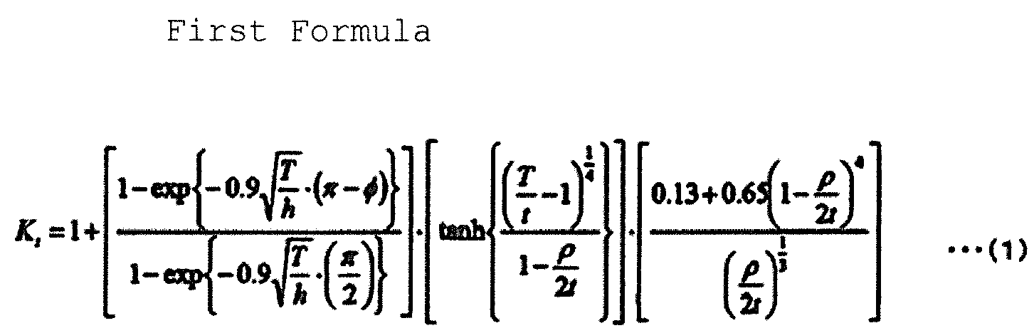
- It is to be noted that φ is the excess metal angle, ρ is the radius of curvature, T is the thickness of an overlapped portion, t is the thickness of a lower plate, and h is the bead height.

- It is to be noted that φ is the excess metal angle, ρ is the radius of curvature, t1 is the thickness of a plate provided with a step portion, t2 is the thickness of a flat plate, and h is the bead height.
- As illustrated in formula (1) and formula (2), the stress concentration factor Kt is reduced when the bead height h illustrated in
FIG. 4 is decreased, and the stress concentration is relieved in both formula (1) and formula (2). - However, when the wettability and the amount of cladding of molten metal for welding metal are the same, the shape of welding buildup affects the shape of the weld metal, after the weld metal is melted and solidified. Consequently, compared with the conventional lap fillet wielding illustrated in
FIG. 4(a) , in the present invention in which welding is performed by forming thestep portion 7 as illustrated inFIG. 4(b) , the bead height h is undoubtedly low. Thus, in the present invention, the stress concentration factor Kt is relieved than that of the conventional lap fillet welding. The fatigue strength of thewelding structure 1 of the present invention in which welding is performed by forming thestep portion 7 is improved more than that of the welding structure that is welded using the conventional lap fillet welding. - In addition, there is a problem in the conventional lap fillet welding in which, welding irregularities tend to occur in the welding direction of arc welding, and fatigue failure tends to occur from the portion where the molten metal for welding is insufficient. Thus, a method capable of uniformly welding in the welding direction has been desired. It is to be noted that the arc welding is performed while placing a welded part such that the surface of the welded part is substantially parallel with the ground.
- In the conventional lap fillet welding, as illustrated in
FIG. 3(a) , the location to be welded is the center (corner portion) of a right-angle portion where an end surface of the tip end portion of theupper side part 9 and the surface of aside wall portion 10a of thelower side part 10 intersect with each other. Thus, theweld toe 11 and theweld toe 12 are the intersection between the welding buildup and the metal plate surface of thelower side part 10, and the intersection between the welding buildup and the metal plate surface of theupper side part 9, respectively. Consequently, the molten metal flows easily on the metal plate surface of thelower side part 10 due to the action of gravity, and when there is a slight variation in the welding conditions or in the surface state of the metal plate, the wettability of the molten metal for welding metal is changed, and welding irregularities tend to occur. - By contrast, in the present invention, as illustrated in
FIG. 3(b) , thestep portion 7 is formed in thelower side part 3. Thus, oneweld toe 11 is on the inclination surface of thestep portion 7, and theother weld toe 12 is at the tip end of the outer surface of theside wall portion 9a of theupper side part 9. Consequently, a groove shape is formed by thelower side part 3 and theupper side part 9. Because the arc welding is performed along the groove shape, even if the welding conditions and the surface state of the metal plate vary to some extent, the molten metal for welding flows so as to accumulate in the grove, due to the action of gravity. Thus, even if irregularities occur in the molten metal in the welding direction, an action for equalizing the irregularities occurs in the molten metal itself, by the interfacial tension of the molten metal and the action of gravity. Consequently, the present invention is capable of stable welding in which welding irregularities seldom occur, and as a result, it is possible to improve the fatigue strength of the welded portion. - In addition, when the welded portion is subject to repeated stress in a direction parallel to the surface of the plate, the fatigue failure tends to occur from the welding toe, and a crack propagates substantially in the plate thickness direction. Herein the
weld toe 12 of one of the weld toes is placed at the same position as the intersection between the welding buildup and the metal plate surface of theupper side part 9, in the conventional lap fillet welding (seeFIG. 4(a) ) as well as in the present invention in which welding is performed by forming the step portion 7 (seeFIG. 4(b) ). In the conventional lap fillet welding, theother weld toe 11 becomes the surface of the lower side part 3 (seeFIG. 4(a) ). Consequently, in the conventional lap fillet welding, the propagation direction of the crack is substantially perpendicular to the surface of thelower side part 3. Thus, the propagation direction of the crack is substantially perpendicular to a direction toward which repeated stress of fatigue is applied (direction parallel to the surface of the lower side part 3). As a result, the propagation length of the crack is reduced. - By contrast, in the present invention in which welding is performed by forming the
step portion 7, the surface of thelower side part 3 is inclined (seeFIG. 4(b) ), and the crack propagates substantially in parallel with the plate thickness direction of theupper side part 9. Consequently, in the present invention, because the crack propagates in an oblique direction relative to the plate thickness direction in thestep portion 7, the propagation length becomes longer than that of the conventional lap fillet welding. As a result, in thewelding structure 1 of the present invention, the fatigue life is improved more than that of the conventional lap fillet welding. - In addition, in the
welding structure 1 according to the present invention, the stiffness of parts will be improved compared with that of the conventional lap fillet welding. More specifically, when thestep portion 7 is formed in thelower side part 3, while the shape of theupper side part 9 is the same as that of the conventional example, the cross-section of thelower side part 3 is inevitably increased. When the same moment is applied, the maximum generated stress on the cross-section at the same position is reduced, when the cross-section modulus is increased. The cross-section modulus is a value determined by the shape of the cross-section, and if the plates have the same plate thickness, the plate with a larger cross-section has a larger cross-section modulus. Thus, the cross-section modulus is increased in thewelding structure 1 according to the present invention, and because the maximum generated stress is reduced, the stiffness is improved. - Next, a preferable shape of the
step portion 7 will be described with reference toFIG. 5. FIG. 5 is an enlarged diagram of a location where theupper side part 9 and thelower side part 3 are fitted with each other inFIG. 1 . InFIG. 5 , the plate thickness of thelower side part 3 is t1, the plate thickness of theupper side part 9 is t2, the height of the step portion 7 (height of bent projection) is D, the distance between the tip end of theupper side part 9 and the lower end of the inclination surface of thestep portion 7 is L1, the fitting length of thelower side part 3 to theupper side part 9 is L2, and the inclination angle of thestep portion 7 is θ. - First, a relation between the height D of the
step portion 7 and the plate thickness t2 of theupper side part 9 is preferably 0.5*t2 ≤ D ≤ 2*t2. In the present invention, the height D of thestep portion 7 does not need to be equal to the plate thickness t2 (D = t2) of the counterpart side part (upper side part 9), and a certain effect can be obtained even when the height D of thestep portion 7 is half or twice of the plate thickness t2 of the counterpart side part (upper side part 9). Thus, the relation between the height D of thestep portion 7 and the plate thickness t2 of theupper side part 9 may be 0.5*t2 ≤ D ≤ 2*t2. This is because when the height of thestep portion 7 is set to a fixed amount or more, the shape of the weld metal is relieved without fail compared with that of the lap fillet welding. - Furthermore, it is not preferable to set the height of the
step portion 7 to exceed 2*t2, because it will be difficult to form theupper side part 9, and assemble theupper side part 9 and thelower side part 3. - The distance L1 between the tip end of the counterpart side part (upper side part 9) and the lower end of the inclination surface of the
step portion 7 is preferably equal to or less than the plate thickness t2 of the counterpart side part (upper side part 9). This is because when the distance L1 is larger than the plate thickness t2, theweld toe 11 of thestep portion 7 side comes into contact with the surface of thelower side part 3, instead of the inclination surface of thestep portion 7. Consequently, the effect due to the difference in shapes compared inFIG. 3(a) and FIG. 3(b) becomes smaller. In this way, the distance L1 is preferably smaller as long as it is within such a range that the tip end of theupper side part 9 does not come into contact with the inclination surface of thestep portion 7. In addition, the inclination angle θ formed by the inclination surface of thestep portion 7 and the joining surface of the counterpart side part (upper side part 9) is preferably 90° ≤ θ ≤ 150°. - The portion where the metal plates of the
upper side part 9 and thelower side part 3 are overlapped with each other is increased, as the fitting length L2 of thelower side part 3 to theupper side part 9 is increased. This increases the stiffness of the part itself in addition to the portion, and the stress generated while the same moment is applied will be reduced. Consequently, the fitting length L2 is preferably longer to improve the fatigue strength. - Although the above explanation represents an example of providing the
step portion 7 by forming thebent projection 5 on the entireside wall portion 3a in the longitudinal direction (direction perpendicular to the paper surface) in thelower side part 3, it is also possible to provide the step-shaped portion of the present invention partially on theside wall portion 3a in the longitudinal direction. - In addition, in the
welding structure 1 according to the present invention, thestep portion 7 is provided by forming thebent projection 5 on both right and leftside wall portions 3a of the one part (lower side part 3). However, thestep portion 7 may be provided by forming thebent projection 5 on either the right or leftside wall portion 3a, and joining with the side wall portion of the other part. - Furthermore, the above explanation represented an example of joining the
lower side part 3 and theupper side part 9 by fitting the tip end of thelower side part 3 into theupper side part 9, while forming thestep portion 7 on thelower side part 3. Conversely, thelower side part 3 and theupper side part 9 may be joined by fitting the tip end of theupper side part 9 into thelower side part 3, while forming thestep portion 7 on theupper side part 9. - A method for manufacturing a welding part according to a Second Embodiment of the present invention manufactures a welding part that includes the
welding structure 1 mainly illustrated inFIG. 1 , and that is made by combining and joining two parts each having an opening portion on at least one side, while the opening portions face each other. As illustrated inFIG. 6 , the method for manufacturing the welding part according to the Second Embodiment includes a bent-projection-forming step (S1), a first press-forming step (S3), a second press-forming step (S5), and a joining step (S7). Hereinafter, the steps will be specifically described with reference toFIG. 7 . - The bent-projection-forming step S1 is a step of forming the
bent projection 5 on a location corresponding to the tip end portion of theside wall portion 3a on ablank sheet 13 in one part, among the welding parts (seeFIG. 7 (a-1) andFIG. 7 (a-2)). - In relation with the plate thickness t2 of the counterpart side part (upper side part 9), the height D of the
bent projection 5 is preferably 0.5*t2 ≤ D ≤ 2*t2. In addition, the inclination angle θ formed by the inclination surface of thestep portion 7 that is formed by thebent projection 5 and the joining surface of the counterpart side part (upper side part 9) is preferably 90° ≤ θ ≤ 150°. - The first press-forming step S3 is a step of press-forming the
blank sheet 13 on which thebent projection 5 has been formed in the bent-projection-forming step S1, using apunch 15 and adie 17, and obtaining thelower side part 3 having theside wall portion 3a. (seeFIG. 7 (a-3)). - The tip end portion of the
side wall portion 3a that has been formed in this step includes thebent projection 5 projecting outwardly that has been formed in the bent-projection-forming step S1. In addition, because theside wall portion 3a has been formed, thelower side part 3 made in this step has a U-shaped cross section having an opening portion on at least one side of the cross-section of thelower side part 3. Because thebent projection 5 has been formed in the bent-projection-forming step S1 before theside wall portion 3a is formed in this step, theside wall portion 3a having thebent projection 5 can be easily formed on the tip end portion. - The second press-forming step S5 is a step of press-forming the
blank sheet 13 using thepunch 15 and thedie 17, and obtaining theupper side part 9 including theside wall portion 9a (seeFIG. 7 (b-1) andFIG. 7 (b-2)). Because theside wall portion 9a is formed, theupper side part 9 that has been made in this step has a U-shaped cross-section having an opening portion on at least one side. - The joining step S7 is a step of fitting the tip end side of the
step portion 7 of thelower side part 3 that has been obtained in the first press-forming step S3 to theside wall portion 9a of theupper side part 9 that has been made in the second press-forming step S5, and linearly joining thelower side part 3 and theupper side part 9 by arc welding. - When the
upper side part 9 and thelower side part 3 are fitted and joined, the distance L1 between the tip end of the plate of theupper side part 9 and the lower end of the inclination surface of thestep portion 7 is preferably the plate thickness t2 of theupper side part 9 or less. The distance L1 is preferably shorter as long as it is within such a range that the tip end of theupper side part 9 does not come into contact with the inclination surface of thestep portion 7. - The portion where the metal plates of the
upper side part 9 and thelower side part 3 are overlapped with each other is increased, as the fitting length L2 of thelower side part 3 to theupper side part 9 is increased. This increases the stiffness of the part itself in addition to the portion, and the stress generated while the same moment is applied will be reduced. Consequently, the fitting length L2 is preferably longer for improvement of the fatigue strength. - The present Second Embodiment has the following effects. For example, similar to the welding part that is manufactured in the present Second Embodiment, a suspension arm for an automobile is made by combining and joining two parts that are formed by press-forming and that each have an opening portion on at least one side of the cross-section, while the opening portions face each other. However, the two parts are not press-formed in a single step, and a drawing step and a without step are performed on the blank sheet that is to be supplied to the press-forming, as the steps performed prior to press-forming the side wall portions of the two parts.
- By forming the bent projection by integrating the bent-projection-forming step according to the present invention into the drawing step and the without step such as the above, it is possible to manufacture the welding part that is economically favorable and that has high fatigue strength, without increasing the number of steps, without requiring a special press-forming device, or without damaging the productivity.
- Experiments were carried out to confirm the effects of the present invention. Hereinafter, the contents of the experiments will be described. Evaluation of durability performance of the parts to be used for the automotive body includes evaluation on the full vehicle by assembling the parts in the actual automotive body, evaluation per part, evaluation by running a basic fatigues test on a sheet (test piece) of a smaller unit, and the like. In the present first example, the performance of the welding structure was evaluated by running the basic fatigue test using a test piece that was made by the welding to provide the step portion according to the present invention (see
FIG. 8(a) ), and by the lap fillet welding of the conventional technology (seeFIG. 8(b) ). - A hot-rolled steel sheet of 980 MPa class having the plate thickness t2 of 2.3 mm was used as a sample.
- A steel sheet of 250 mm × 175 mm in size was cut out from the sample. In
FIG. 8(a) , a welding cross-section of a test piece that was welded by forming thestep portion 7 is illustrated as an example of the present invention. In the example of the present invention, thebent projection 5 was formed in the vicinity of the end portion of the cutout steel sheet on one 250-mm length side, by bending and forming using a bender. In this step, the height (depth) D of thestep portion 7 that is provided by forming thebent projection 5 is 2.3 mm being equivalent to the plate thickness t2 of the sample. In addition, the inclination angle θ of thestep portion 7 that is formed by thebent projection 5 is 135°, and the distance L1 between the tip end of theupper side part 9 and the lower end of the inclination surface of thestep portion 7 is 2 mm. - Next, the test piece including the welding structure of the present invention was made by overlapping the end portion of the steel sheet as being cut out, on the end portion side of the steel sheet to which the
bent projection 5 was formed, and performing metal active gas (MAG) arc welding on the end surface of the steel sheet side as being cut out. Then, a strip having a width of 30 mm was cut out from the test piece, and a plane bending-fatigue-test piece 19 was made from the strip. As illustrated inFIG. 9 , the height of the plane bending-fatigue-test piece 19 was 90 mm, the width was 30 mm, and the width of the center portion was 22 mm. - In
FIG. 8(b) , a welding cross-section of a test piece that was made by the lap fillet welding of the convention technology is illustrated as a comparative example. In the comparative example, the steel sheets as being cut out from the sample were overlapped with each other, and formed using the MAG arc welding. A strip having a width of 30 mm was cut out from the welded steel sheets, and the plane bending-fatigue-test piece 19 having the shape illustrated inFIG. 9 was made from the strip. - In the example of the present invention as well as in the comparative example, an overlapping margin (fitting length) L2 of the steel sheets was 5 mm. A weld bead width W was 5.5 mm or 7 mm so as to be the same in the example of the present invention and the comparative example.
- In the example of the present invention as well as in the comparative example, the arc welding conditions include welding current of 185 A or 205 A, voltage of 19 V or 23 V, welding speed of 85 cm/min, and shield gas of Ar-20%CO2, and a welding wire for high tensile strength steel of 780 MPa class having a diameter of 1.2 mm was used. The arc welding conditions are illustrated in Table 1.
Table 1 No. Arc welding conditions Fatigue test Note Current (A) Voltage (V) Speed (cm/min) Welding wire Welding bead width (mm) Target stress (MPa) Repeated times 1 205 23 85 780-MPa class high tensile strength steel (φ1.2) 7 600 69400 Comparative example 2 500 136500 Comparative example 3 400 613300 Comparative example 4 205 23 85 780-MPa class high tensile strength steel (φ1.2) 7 600 149900 Example of present invention 5 500 565700 Example of present invention 6 450 1400000 Example of present invention 7 400 10000000 (unbroken) Example of present invention 8 185 19 85 780-MPa class high tensile strength steel (φ1.2) 5.5 500 130600 Comparative example 9 400 330300 Comparative example 10 300 10000000 (unbroken) Comparative example 11 185 19 85 780-MPa class high tensile strength steel (φ1.2) 5.5 600 188300 Example of present invention 12 500 826200 Example of present invention 13 400 10000000 (unbroken) Example of present invention - The fatigue test was performed using pulsating plane bending (see
FIG. 10 ). PBF-30 manufactured by Tokyo Koki was used as a testing machine, and the testing machine was installed so that the welding bead of the plane bending-fatigue-test piece 19 is facing downward. In this state, the plane bending-fatigue-test piece 19 was installed so that the upper plate was fixed to the driving arm side of the testing machine, and the lower plate was fixed to the measuring swing arm side of the testing machine. Consequently, the center portion of the lower plate in the plate thickness direction becomes a bending neutral surface. The test was performed by repeatedly applying load on the plane bending-fatigue-test piece 19 via the driving arm so that the target stress is applied, until a crack was generated on the plane bending-fatigue-test piece 19. The stress applied to the plane bending-fatigue-test piece 19 was obtained by the moment that was measured via the measuring arm, and the plate thickness and the plate width (average value of the upper plate and the lower plate) of the plane bending-fatigue-test piece 19. The fatigue test conditions include the stress ratio of 0 (pulsating) and the test frequency of 20 Hz. The fatigue test was terminated after 10,000,000 times at maximum. - The results of the fatigue test are illustrated in Table 3, which will be described later. The example of the present invention is the welding to provide the
step portion 7, and the comparative example is the conventional lap fillet welding. As illustrated in Table 3, regardless of the welding conditions, the fatigue life in the example of the present invention significantly exceeded that in the comparative example. - In general, a suspension arm for an automotive body requires strength, and often has a closed cross-sectional shape by fitting two parts that are produced by press-forming and that each have an opening portion to each other. In the second example, the
suspension arm 21 illustrated inFIG. 11 is manufactured. The present invention and the conventional technology were compared by running a fatigue test on thesuspension arm 21 that was made by performing the lap fillet welding of the convention technology or by performing the welding to provide the step portion of the present invention, on the welding portion (step-portion-setting units P1, P2, and P3) of the two parts. - Two parts that configure the
suspension arm 21 are parts obtained by press-forming a hot-rolled steel sheet of 980 MPa class having the plate thickness t2 of 2.3 mm, into a U-shaped cross-section. Onepart 29 has the same shape in the example of the present invention as well as the conventional example. The arc welding conditions include current of 185 A, voltage of 23 V, welding speed of 85 cm/min, and shield gas of Ar-20%CO2, and a welding wire for high tensile strength steel of 780 Mpa class having the diameter of 1.2 mm was used. - In the conventional example, a
step portion 27 is not formed on anotherpart 23, and the lap fillet welding was performed on all the welding portions (P1 to P3 inFIG. 11 ). On the other hand, in the example of the present invention, thestep portion 27 was provided by forming the bent projection on the side wall portion of theother part 23, and theother part 23 and thepart 29 were fitted and linearly joined by arc welding. - In the example of the present invention, the height D of the
step portion 27 that was provided by forming abent projection 25 on theother part 23 was made twice the plate thickness t2 (D = 2*t2) inFIG. 12(b) , and was made half the plate thickness t2 (D = 0.5*t2) inFIG. 12(c) . The location where thestep portion 27 was provided by forming thebent projection 25 was under two conditions of all the step-portion-setting units P1, P2, and P3 illustrated inFIG. 11 , and of only the step-portion-setting unit P3. The height of the step portion and the conditions of the step-portion-setting unit in the example are illustrated in Table 2.Table 2 Height of step portion D (mm) Step portion setting unit Conventional example - - First example 1.15 P1, P2, P3 Second example 4.60 P3 Third example 2.30 P1, P2, P3 - As illustrated in
FIG. 13 , in the fatigue test, the automotive body fixing side of thesuspension arm 21 was restrained (binding points A1 and A2), and the load was applied from the wheel fixing side (input point B). As the binding conditions, at a binding point A1 (horizontal bush), the translational motion (displacement) in an X axis direction (automotive longitudinal direction), a Y axis direction (automotive width direction), and a Z axis direction (automotive vertical direction) was restrained, and only the rotary motion around the axes was allowed. At the binding portion A2 (side bush), the displacement in the Y axis direction and the Z axis direction was restrained, and the displacement in the X axis direction and the rotary motion around the axes were allowed. - As the load conditions, at an input point B, a load of 8000 N at a frequency of 2.5 Hz was repeatedly applied in the X axis direction, the displacement in the Y axis direction and the Z axis direction was restrained, and the displacement in the X axis direction and the rotary motion in all directions were allowed. The fatigue test was conducted to evaluate the number of times the load was repeatedly applied, until a crack was generated on the welding portion of the two parts.
- The results of the fatigue test are illustrated in Table 3.
Table 3 Repeated number of times until crack is generated Conventional example 50000 First example 80000 Second example 100000 Third example 120000 - As illustrated in Table 3, in the example of the present invention in which welding is performed by forming the
step portion 27, the repeated number of times until a crack is generated is increased, compared with that of the conventional example. Consequently, the fatigue life was increased when thestep portion 27 was formed to join the two parts. - As described above, the fatigue strength of the welded portion was increased when the two parts are joined by forming a step portion on the location where the two parts are to be joined, compared with that of the conventional lap fillet welding. Consequently, the effects of increasing the fatigue life of the welding part have been demonstrated. In addition, by forming the bent projection to provide the step portion, the cross-section modulus of the welding part is increased. Thus, the stiffness is also increased, and the weight reduction of automobile can also be advantageously expected.
- Moreover, in the example, the fatigue test was performed on the suspension arm. However, the present invention may be easily applied to manufacturing of a suspension frame and a chassis frame that require high strength, at the welding part that has a closed cross-sectional shape by joining two parts. Consequently, it is possible to improve the fatigue strength and the stiffness.
- Because the present invention can improve the fatigue strength of the welding part, the present invention is applicable to a welding structure of a press-formed part, a structural part for an automotive body including the welding structure, and a method for manufacturing a welding part.
-
- 1 welding structure
- 3 lower side part
- 3a side wall portion (lower side part)
- 5 bent projection
- 7 step portion
- 9 upper side part
- 9a side wall portion (upper side part)
- 10 lower side part
- 10a side wall portion (lower side part)
- 11 weld toe (lower side part side)
- 12 weld toe (upper side part side)
- 13 blank sheet
- 15 punch
- 17 die
- 19 plane bending fatigue test piece
- 21 suspension arm
- 23 part
- 25 bent projection
- 27 step portion
- 29 part
Claims (5)
- A welding structure of a press-formed part that is made by combining and joining two parts that are formed by press-forming and that each have an opening portion on at least one side of a cross-section, while the opening portions face each other, the welding structure comprising:a step portion that is provided by forming a bent projection projecting outwardly on a tip end portion of a side wall portion of one part, partially or entirely on a joining surface, whereina tip end side of the step portion is fitted into the opening portion of another part, andthe step portion of the one part and a tip end of a side wall portion of the other part are linearly joined by arc welding.
- The welding structure of the press-formed part according to claim 1, wherein the one part and the other part are linearly welded so that an excess weld metal comes into contact with an inclination surface of the step portion.
- The welding structure of the press-formed part according to claim 1 or 2, wherein when height of the step portion is D and a plate thickness of the other part is t2, a relation of 0.5*t2≤D≤2*t2 is satisfied.
- A structural part for an automotive body including the welding structure of the press-formed part according to any one of claims 1 to 3.
- A method for manufacturing a welding part that is made by combining and joining two parts that are formed by press-forming and that each have an opening portion on at least one side of a cross-section, while the opening portions face each other, the method comprising:a bent-projection-forming step of providing a step portion by forming a bent projection at a location corresponding to a tip end portion of a side wall portion on a blank sheet in one part;a first press-forming step of manufacturing one part having an opening portion by forming the side wall portion of the blank sheet on which the bent projection is formed;a second press-forming step of manufacturing another part having an opening portion by forming a side wall portion on a blank sheet; anda joining step of linearly joining the step portion of the one part and a tip end of the side wall portion of the other part, by fitting a tip end side of the step portion of the one part into the opening portion of the other part, by arc welding.
Applications Claiming Priority (2)
| Application Number | Priority Date | Filing Date | Title |
|---|---|---|---|
| JP2015025531A JP6168077B2 (en) | 2015-02-12 | 2015-02-12 | Press-molded part joining structure, automotive structural part having the joining structure, and method of manufacturing the joined part |
| PCT/JP2016/052321 WO2016129389A1 (en) | 2015-02-12 | 2016-01-27 | Structure for bonding press-molded article, structural article for automobile having said bonding structure, and method for manufacturing bonded article |
Publications (3)
| Publication Number | Publication Date |
|---|---|
| EP3257690A1 true EP3257690A1 (en) | 2017-12-20 |
| EP3257690A4 EP3257690A4 (en) | 2018-03-14 |
| EP3257690B1 EP3257690B1 (en) | 2025-01-15 |
Family
ID=56615367
Family Applications (1)
| Application Number | Title | Priority Date | Filing Date |
|---|---|---|---|
| EP16749034.1A Active EP3257690B1 (en) | 2015-02-12 | 2016-01-27 | Structure for bonding press-molded article, structural article for automobile having said bonding structure, and method for manufacturing bonded article |
Country Status (7)
| Country | Link |
|---|---|
| US (1) | US20180009050A1 (en) |
| EP (1) | EP3257690B1 (en) |
| JP (1) | JP6168077B2 (en) |
| KR (1) | KR101967571B1 (en) |
| CN (1) | CN107206858B (en) |
| MX (1) | MX2017010266A (en) |
| WO (1) | WO2016129389A1 (en) |
Families Citing this family (21)
| Publication number | Priority date | Publication date | Assignee | Title |
|---|---|---|---|---|
| WO2018129256A1 (en) * | 2017-01-06 | 2018-07-12 | Keystone Tower Systems, Inc. | Tube stiffening |
| CN110337344B (en) * | 2017-02-28 | 2022-05-13 | 杰富意钢铁株式会社 | Overlap fillet arc welding head and manufacturing method thereof |
| CN110691884A (en) * | 2017-10-05 | 2020-01-14 | 株式会社野泽 | Mounting metal member for building panel and mounting structure for building panel using the same |
| JP6863218B2 (en) * | 2017-10-12 | 2021-04-21 | トヨタ自動車株式会社 | Suspension arm welding method |
| CN111433056B (en) * | 2017-11-27 | 2023-06-02 | 日本制铁株式会社 | Structural component |
| JP6922753B2 (en) * | 2018-01-16 | 2021-08-18 | Jfeスチール株式会社 | Welded joint structure and welded joint method |
| JP7073732B2 (en) * | 2018-01-16 | 2022-05-24 | 大同特殊鋼株式会社 | Appearance evaluation method and appearance evaluation device for weld beads |
| DE102018210174A1 (en) * | 2018-06-22 | 2019-12-24 | Thyssenkrupp Ag | Process for producing a carrier and a lead or box frame |
| JP7181016B2 (en) * | 2018-06-29 | 2022-11-30 | 株式会社神戸製鋼所 | Bonded structure and manufacturing method thereof |
| JP7143186B2 (en) | 2018-11-12 | 2022-09-28 | 三菱重工業株式会社 | Parts manufacturing method, processing equipment and parts |
| DE102018131754A1 (en) * | 2018-12-11 | 2020-06-18 | Bayerische Motoren Werke Aktiengesellschaft | Process for the production of vehicle spare parts |
| CN109500486B (en) * | 2018-12-22 | 2023-01-03 | 山西汾西重工有限责任公司 | Method for positioning and welding longitudinal butt joint of aluminum alloy thick plate rolling shell |
| JP7269469B2 (en) * | 2019-03-13 | 2023-05-09 | 日本製鉄株式会社 | Suspension arm and automobile suspension structure |
| JP2022137736A (en) * | 2021-03-09 | 2022-09-22 | 株式会社ワイテック | Arc-welding method |
| US11724746B2 (en) * | 2021-10-13 | 2023-08-15 | GM Global Technology Operations LLC | Chassis assembly having mixed materials |
| US12157277B2 (en) | 2021-12-30 | 2024-12-03 | Rohr, Inc. | Vibration welding fiber-reinforced composite aircraft structures |
| EP4241967A1 (en) | 2022-03-07 | 2023-09-13 | Rohr, Inc. | Shimming welded interface(s) between thermoplastic components |
| JP7810888B2 (en) * | 2022-04-01 | 2026-02-04 | 日本製鉄株式会社 | METAL MEMBER MANUFACTURING METHOD AND METAL MEMBER |
| KR102504571B1 (en) * | 2022-04-22 | 2023-03-02 | 기승공업(주) | Rear Trailing Arm Processing Method and Mold of Automotive Suspension Device |
| WO2024210057A1 (en) * | 2023-04-03 | 2024-10-10 | 日本製鉄株式会社 | Structural member |
| JP7538462B1 (en) * | 2023-04-03 | 2024-08-22 | 日本製鉄株式会社 | Structural members |
Family Cites Families (16)
| Publication number | Priority date | Publication date | Assignee | Title |
|---|---|---|---|---|
| DE417167C (en) * | 1922-02-16 | 1925-08-06 | Eugen Wolf Dr | Connection of metal parts produced by autogenous welding |
| JPS57139475U (en) * | 1981-02-26 | 1982-08-31 | ||
| JPS5896869U (en) * | 1981-12-25 | 1983-07-01 | トヨタ自動車株式会社 | Arc welded joint structure of thin steel plate |
| FR2520648B1 (en) * | 1982-01-29 | 1986-06-13 | Cimt Lorraine | METHOD OF ASSEMBLING BY EDGE-TO-EDGE WELDING OF PROFILES AND WALL OBTAINED BY THIS METHOD |
| JPH0244627B2 (en) * | 1986-06-16 | 1990-10-04 | Seiwa Kogyosho Kk | DENKIONSUIKITONOKANTAINOSEIZOHOHO |
| JPS635873A (en) * | 1986-06-25 | 1988-01-11 | Diesel Kiki Co Ltd | Welding method for pipe and pipe |
| JPH079135A (en) * | 1993-06-25 | 1995-01-13 | Fuji Heavy Ind Ltd | Coupling method for plate member |
| US5476210A (en) * | 1993-06-25 | 1995-12-19 | Fuji Jukogyo Kabushiki Kaisha | Structure for joining plate elements and method for joining the same |
| JPH10113717A (en) * | 1996-10-11 | 1998-05-06 | Nakajima Kokan Kk | Production of square steel tube |
| JP3362624B2 (en) | 1997-01-10 | 2003-01-07 | 日本鋼管株式会社 | Method for improving fatigue characteristics of lap welded joints |
| JP4587411B2 (en) * | 1999-08-04 | 2010-11-24 | 東プレ株式会社 | Lap welding method |
| FI110238B (en) * | 2001-01-31 | 2002-12-31 | Innowork Oy | Process for making a box beam and according to the method a box beam and structural part for a box beam |
| GB2403172A (en) * | 2003-06-17 | 2004-12-29 | Bamford Excavators Ltd | Method of forming a metal box section |
| JP6373550B2 (en) | 2011-03-31 | 2018-08-15 | Jfeスチール株式会社 | Gas shield arc welding method |
| JP5617813B2 (en) | 2011-10-11 | 2014-11-05 | トヨタ自動車株式会社 | Suspension arm |
| JP5898576B2 (en) | 2012-06-25 | 2016-04-06 | 株式会社神戸製鋼所 | Multilayer arc welded joint manufacturing method |
-
2015
- 2015-02-12 JP JP2015025531A patent/JP6168077B2/en active Active
-
2016
- 2016-01-27 KR KR1020177022523A patent/KR101967571B1/en active Active
- 2016-01-27 CN CN201680009443.4A patent/CN107206858B/en active Active
- 2016-01-27 MX MX2017010266A patent/MX2017010266A/en unknown
- 2016-01-27 US US15/546,554 patent/US20180009050A1/en not_active Abandoned
- 2016-01-27 WO PCT/JP2016/052321 patent/WO2016129389A1/en not_active Ceased
- 2016-01-27 EP EP16749034.1A patent/EP3257690B1/en active Active
Also Published As
| Publication number | Publication date |
|---|---|
| EP3257690A4 (en) | 2018-03-14 |
| JP2016147593A (en) | 2016-08-18 |
| WO2016129389A1 (en) | 2016-08-18 |
| KR101967571B1 (en) | 2019-04-09 |
| CN107206858A (en) | 2017-09-26 |
| KR20170105062A (en) | 2017-09-18 |
| CN107206858B (en) | 2020-05-19 |
| JP6168077B2 (en) | 2017-07-26 |
| US20180009050A1 (en) | 2018-01-11 |
| MX2017010266A (en) | 2018-02-13 |
| EP3257690B1 (en) | 2025-01-15 |
Similar Documents
| Publication | Publication Date | Title |
|---|---|---|
| EP3257690B1 (en) | Structure for bonding press-molded article, structural article for automobile having said bonding structure, and method for manufacturing bonded article | |
| CN106458122B (en) | Car body component | |
| JP5843015B2 (en) | Method for forming fillet arc welded joint and fillet arc welded joint | |
| US10202012B2 (en) | Suspension link and production method therefor | |
| JP6265089B2 (en) | Method for improving fatigue strength of automotive suspension parts | |
| US10590974B2 (en) | Lap fillet arc-welded joint | |
| KR20210143267A (en) | Joint structure, automobile parts and manufacturing method of joint structure | |
| CN103648812A (en) | Door sash | |
| KR101987607B1 (en) | Bonding structure of overlaid fillet arc weld joint and press-formed part | |
| US20190358732A1 (en) | Method for joining dissimilar materials, and dissimilar-material joined body | |
| WO2011034203A1 (en) | Curved closed-section structural component and method for manufacturing same | |
| WO2020209357A1 (en) | Blank and structural member | |
| JP2019073152A (en) | Side rail and manufacturing method for side rail | |
| US12194806B2 (en) | Suspension arm | |
| JP2006306211A (en) | Tailored blank welded structural members | |
| JP3838787B2 (en) | Triangular tube manufacturing method and molding die thereof | |
| JP2017196950A (en) | Joint structure and joint structure manufacturing method | |
| CN203666778U (en) | Frame longitudinal beam and frame | |
| CN102372220B (en) | Passenger conveying equipment | |
| JP4764015B2 (en) | Manufacturing method of bonded metal plate | |
| KR100551814B1 (en) | Split frame joint structure for automobile | |
| CN1781796A (en) | Hydraulic forming part with internal partition | |
| JP6922753B2 (en) | Welded joint structure and welded joint method | |
| CN112689571A (en) | Vehicle door frame |
Legal Events
| Date | Code | Title | Description |
|---|---|---|---|
| STAA | Information on the status of an ep patent application or granted ep patent |
Free format text: STATUS: THE INTERNATIONAL PUBLICATION HAS BEEN MADE |
|
| PUAI | Public reference made under article 153(3) epc to a published international application that has entered the european phase |
Free format text: ORIGINAL CODE: 0009012 |
|
| STAA | Information on the status of an ep patent application or granted ep patent |
Free format text: STATUS: REQUEST FOR EXAMINATION WAS MADE |
|
| 17P | Request for examination filed |
Effective date: 20170717 |
|
| AK | Designated contracting states |
Kind code of ref document: A1 Designated state(s): AL AT BE BG CH CY CZ DE DK EE ES FI FR GB GR HR HU IE IS IT LI LT LU LV MC MK MT NL NO PL PT RO RS SE SI SK SM TR |
|
| AX | Request for extension of the european patent |
Extension state: BA ME |
|
| A4 | Supplementary search report drawn up and despatched |
Effective date: 20180213 |
|
| RIC1 | Information provided on ipc code assigned before grant |
Ipc: B21D 53/88 20060101ALI20180207BHEP Ipc: B60G 7/00 20060101AFI20180207BHEP Ipc: B23K 101/00 20060101ALN20180207BHEP Ipc: B23K 33/00 20060101ALI20180207BHEP Ipc: B62D 21/00 20060101ALI20180207BHEP Ipc: B23K 9/00 20060101ALI20180207BHEP Ipc: B23K 9/235 20060101ALI20180207BHEP Ipc: B23K 9/02 20060101ALI20180207BHEP Ipc: B62D 21/02 20060101ALI20180207BHEP Ipc: B21C 37/08 20060101ALI20180207BHEP Ipc: B21D 22/26 20060101ALI20180207BHEP |
|
| DAV | Request for validation of the european patent (deleted) | ||
| DAX | Request for extension of the european patent (deleted) | ||
| STAA | Information on the status of an ep patent application or granted ep patent |
Free format text: STATUS: EXAMINATION IS IN PROGRESS |
|
| 17Q | First examination report despatched |
Effective date: 20210401 |
|
| GRAP | Despatch of communication of intention to grant a patent |
Free format text: ORIGINAL CODE: EPIDOSNIGR1 |
|
| STAA | Information on the status of an ep patent application or granted ep patent |
Free format text: STATUS: GRANT OF PATENT IS INTENDED |
|
| RIC1 | Information provided on ipc code assigned before grant |
Ipc: B23K 101/00 20060101ALN20240307BHEP Ipc: B21C 37/08 20060101ALI20240307BHEP Ipc: B62D 21/02 20060101ALI20240307BHEP Ipc: B62D 21/00 20060101ALI20240307BHEP Ipc: B23K 33/00 20060101ALI20240307BHEP Ipc: B23K 9/235 20060101ALI20240307BHEP Ipc: B23K 9/02 20060101ALI20240307BHEP Ipc: B23K 9/00 20060101ALI20240307BHEP Ipc: B21D 53/88 20060101ALI20240307BHEP Ipc: B21D 22/26 20060101ALI20240307BHEP Ipc: B60G 7/00 20060101AFI20240307BHEP |
|
| INTG | Intention to grant announced |
Effective date: 20240320 |
|
| RIC1 | Information provided on ipc code assigned before grant |
Ipc: B23K 101/00 20060101ALN20240307BHEP Ipc: B21C 37/08 20060101ALI20240307BHEP Ipc: B62D 21/02 20060101ALI20240307BHEP Ipc: B62D 21/00 20060101ALI20240307BHEP Ipc: B23K 33/00 20060101ALI20240307BHEP Ipc: B23K 9/235 20060101ALI20240307BHEP Ipc: B23K 9/02 20060101ALI20240307BHEP Ipc: B23K 9/00 20060101ALI20240307BHEP Ipc: B21D 53/88 20060101ALI20240307BHEP Ipc: B21D 22/26 20060101ALI20240307BHEP Ipc: B60G 7/00 20060101AFI20240307BHEP |
|
| GRAJ | Information related to disapproval of communication of intention to grant by the applicant or resumption of examination proceedings by the epo deleted |
Free format text: ORIGINAL CODE: EPIDOSDIGR1 |
|
| STAA | Information on the status of an ep patent application or granted ep patent |
Free format text: STATUS: EXAMINATION IS IN PROGRESS |
|
| INTC | Intention to grant announced (deleted) | ||
| RIC1 | Information provided on ipc code assigned before grant |
Ipc: B23K 101/00 20060101ALN20240815BHEP Ipc: B21C 37/08 20060101ALI20240815BHEP Ipc: B62D 21/02 20060101ALI20240815BHEP Ipc: B62D 21/00 20060101ALI20240815BHEP Ipc: B23K 33/00 20060101ALI20240815BHEP Ipc: B23K 9/235 20060101ALI20240815BHEP Ipc: B23K 9/02 20060101ALI20240815BHEP Ipc: B23K 9/00 20060101ALI20240815BHEP Ipc: B21D 53/88 20060101ALI20240815BHEP Ipc: B21D 22/26 20060101ALI20240815BHEP Ipc: B60G 7/00 20060101AFI20240815BHEP |
|
| GRAP | Despatch of communication of intention to grant a patent |
Free format text: ORIGINAL CODE: EPIDOSNIGR1 |
|
| STAA | Information on the status of an ep patent application or granted ep patent |
Free format text: STATUS: GRANT OF PATENT IS INTENDED |
|
| RIC1 | Information provided on ipc code assigned before grant |
Ipc: B23K 101/00 20060101ALN20240916BHEP Ipc: B21C 37/08 20060101ALI20240916BHEP Ipc: B62D 21/02 20060101ALI20240916BHEP Ipc: B62D 21/00 20060101ALI20240916BHEP Ipc: B23K 33/00 20060101ALI20240916BHEP Ipc: B23K 9/235 20060101ALI20240916BHEP Ipc: B23K 9/02 20060101ALI20240916BHEP Ipc: B23K 9/00 20060101ALI20240916BHEP Ipc: B21D 53/88 20060101ALI20240916BHEP Ipc: B21D 22/26 20060101ALI20240916BHEP Ipc: B60G 7/00 20060101AFI20240916BHEP |
|
| INTG | Intention to grant announced |
Effective date: 20240927 |
|
| GRAS | Grant fee paid |
Free format text: ORIGINAL CODE: EPIDOSNIGR3 |
|
| GRAA | (expected) grant |
Free format text: ORIGINAL CODE: 0009210 |
|
| STAA | Information on the status of an ep patent application or granted ep patent |
Free format text: STATUS: THE PATENT HAS BEEN GRANTED |
|
| AK | Designated contracting states |
Kind code of ref document: B1 Designated state(s): AL AT BE BG CH CY CZ DE DK EE ES FI FR GB GR HR HU IE IS IT LI LT LU LV MC MK MT NL NO PL PT RO RS SE SI SK SM TR |
|
| REG | Reference to a national code |
Ref country code: CH Ref legal event code: EP Ref country code: GB Ref legal event code: FG4D |
|
| REG | Reference to a national code |
Ref country code: DE Ref legal event code: R096 Ref document number: 602016090948 Country of ref document: DE |
|
| REG | Reference to a national code |
Ref country code: IE Ref legal event code: FG4D |
|
| REG | Reference to a national code |
Ref country code: NL Ref legal event code: MP Effective date: 20250115 |
|
| PG25 | Lapsed in a contracting state [announced via postgrant information from national office to epo] |
Ref country code: NL Free format text: LAPSE BECAUSE OF FAILURE TO SUBMIT A TRANSLATION OF THE DESCRIPTION OR TO PAY THE FEE WITHIN THE PRESCRIBED TIME-LIMIT Effective date: 20250115 |
|
| PG25 | Lapsed in a contracting state [announced via postgrant information from national office to epo] |
Ref country code: RS Free format text: LAPSE BECAUSE OF FAILURE TO SUBMIT A TRANSLATION OF THE DESCRIPTION OR TO PAY THE FEE WITHIN THE PRESCRIBED TIME-LIMIT Effective date: 20250415 |
|
| PG25 | Lapsed in a contracting state [announced via postgrant information from national office to epo] |
Ref country code: FI Free format text: LAPSE BECAUSE OF FAILURE TO SUBMIT A TRANSLATION OF THE DESCRIPTION OR TO PAY THE FEE WITHIN THE PRESCRIBED TIME-LIMIT Effective date: 20250115 |
|
| PG25 | Lapsed in a contracting state [announced via postgrant information from national office to epo] |
Ref country code: PL Free format text: LAPSE BECAUSE OF FAILURE TO SUBMIT A TRANSLATION OF THE DESCRIPTION OR TO PAY THE FEE WITHIN THE PRESCRIBED TIME-LIMIT Effective date: 20250115 |
|
| PG25 | Lapsed in a contracting state [announced via postgrant information from national office to epo] |
Ref country code: ES Free format text: LAPSE BECAUSE OF FAILURE TO SUBMIT A TRANSLATION OF THE DESCRIPTION OR TO PAY THE FEE WITHIN THE PRESCRIBED TIME-LIMIT Effective date: 20250115 |
|
| REG | Reference to a national code |
Ref country code: LT Ref legal event code: MG9D |
|
| PG25 | Lapsed in a contracting state [announced via postgrant information from national office to epo] |
Ref country code: IS Free format text: LAPSE BECAUSE OF FAILURE TO SUBMIT A TRANSLATION OF THE DESCRIPTION OR TO PAY THE FEE WITHIN THE PRESCRIBED TIME-LIMIT Effective date: 20250515 Ref country code: NO Free format text: LAPSE BECAUSE OF FAILURE TO SUBMIT A TRANSLATION OF THE DESCRIPTION OR TO PAY THE FEE WITHIN THE PRESCRIBED TIME-LIMIT Effective date: 20250415 |
|
| REG | Reference to a national code |
Ref country code: AT Ref legal event code: MK05 Ref document number: 1759644 Country of ref document: AT Kind code of ref document: T Effective date: 20250115 |
|
| PG25 | Lapsed in a contracting state [announced via postgrant information from national office to epo] |
Ref country code: HR Free format text: LAPSE BECAUSE OF FAILURE TO SUBMIT A TRANSLATION OF THE DESCRIPTION OR TO PAY THE FEE WITHIN THE PRESCRIBED TIME-LIMIT Effective date: 20250115 |
|
| PG25 | Lapsed in a contracting state [announced via postgrant information from national office to epo] |
Ref country code: PT Free format text: LAPSE BECAUSE OF FAILURE TO SUBMIT A TRANSLATION OF THE DESCRIPTION OR TO PAY THE FEE WITHIN THE PRESCRIBED TIME-LIMIT Effective date: 20250515 Ref country code: LV Free format text: LAPSE BECAUSE OF FAILURE TO SUBMIT A TRANSLATION OF THE DESCRIPTION OR TO PAY THE FEE WITHIN THE PRESCRIBED TIME-LIMIT Effective date: 20250115 |
|
| PG25 | Lapsed in a contracting state [announced via postgrant information from national office to epo] |
Ref country code: BG Free format text: LAPSE BECAUSE OF FAILURE TO SUBMIT A TRANSLATION OF THE DESCRIPTION OR TO PAY THE FEE WITHIN THE PRESCRIBED TIME-LIMIT Effective date: 20250115 Ref country code: GR Free format text: LAPSE BECAUSE OF FAILURE TO SUBMIT A TRANSLATION OF THE DESCRIPTION OR TO PAY THE FEE WITHIN THE PRESCRIBED TIME-LIMIT Effective date: 20250416 |
|
| PG25 | Lapsed in a contracting state [announced via postgrant information from national office to epo] |
Ref country code: AT Free format text: LAPSE BECAUSE OF FAILURE TO SUBMIT A TRANSLATION OF THE DESCRIPTION OR TO PAY THE FEE WITHIN THE PRESCRIBED TIME-LIMIT Effective date: 20250115 |
|
| REG | Reference to a national code |
Ref country code: CH Ref legal event code: PL |
|
| PG25 | Lapsed in a contracting state [announced via postgrant information from national office to epo] |
Ref country code: SE Free format text: LAPSE BECAUSE OF FAILURE TO SUBMIT A TRANSLATION OF THE DESCRIPTION OR TO PAY THE FEE WITHIN THE PRESCRIBED TIME-LIMIT Effective date: 20250115 |
|
| PG25 | Lapsed in a contracting state [announced via postgrant information from national office to epo] |
Ref country code: LU Free format text: LAPSE BECAUSE OF NON-PAYMENT OF DUE FEES Effective date: 20250127 |
|
| PG25 | Lapsed in a contracting state [announced via postgrant information from national office to epo] |
Ref country code: SM Free format text: LAPSE BECAUSE OF FAILURE TO SUBMIT A TRANSLATION OF THE DESCRIPTION OR TO PAY THE FEE WITHIN THE PRESCRIBED TIME-LIMIT Effective date: 20250115 |
|
| PG25 | Lapsed in a contracting state [announced via postgrant information from national office to epo] |
Ref country code: DK Free format text: LAPSE BECAUSE OF FAILURE TO SUBMIT A TRANSLATION OF THE DESCRIPTION OR TO PAY THE FEE WITHIN THE PRESCRIBED TIME-LIMIT Effective date: 20250115 |
|
| PG25 | Lapsed in a contracting state [announced via postgrant information from national office to epo] |
Ref country code: MC Free format text: LAPSE BECAUSE OF FAILURE TO SUBMIT A TRANSLATION OF THE DESCRIPTION OR TO PAY THE FEE WITHIN THE PRESCRIBED TIME-LIMIT Effective date: 20250115 |
|
| PG25 | Lapsed in a contracting state [announced via postgrant information from national office to epo] |
Ref country code: IT Free format text: LAPSE BECAUSE OF FAILURE TO SUBMIT A TRANSLATION OF THE DESCRIPTION OR TO PAY THE FEE WITHIN THE PRESCRIBED TIME-LIMIT Effective date: 20250115 |
|
| PG25 | Lapsed in a contracting state [announced via postgrant information from national office to epo] |
Ref country code: BE Free format text: LAPSE BECAUSE OF NON-PAYMENT OF DUE FEES Effective date: 20250131 |
|
| REG | Reference to a national code |
Ref country code: DE Ref legal event code: R097 Ref document number: 602016090948 Country of ref document: DE |
|
| PG25 | Lapsed in a contracting state [announced via postgrant information from national office to epo] |
Ref country code: CH Free format text: LAPSE BECAUSE OF NON-PAYMENT OF DUE FEES Effective date: 20250131 |
|
| PG25 | Lapsed in a contracting state [announced via postgrant information from national office to epo] |
Ref country code: EE Free format text: LAPSE BECAUSE OF FAILURE TO SUBMIT A TRANSLATION OF THE DESCRIPTION OR TO PAY THE FEE WITHIN THE PRESCRIBED TIME-LIMIT Effective date: 20250115 Ref country code: CZ Free format text: LAPSE BECAUSE OF FAILURE TO SUBMIT A TRANSLATION OF THE DESCRIPTION OR TO PAY THE FEE WITHIN THE PRESCRIBED TIME-LIMIT Effective date: 20250115 |
|
| REG | Reference to a national code |
Ref country code: BE Ref legal event code: MM Effective date: 20250131 |
|
| PG25 | Lapsed in a contracting state [announced via postgrant information from national office to epo] |
Ref country code: RO Free format text: LAPSE BECAUSE OF FAILURE TO SUBMIT A TRANSLATION OF THE DESCRIPTION OR TO PAY THE FEE WITHIN THE PRESCRIBED TIME-LIMIT Effective date: 20250115 |
|
| PG25 | Lapsed in a contracting state [announced via postgrant information from national office to epo] |
Ref country code: SK Free format text: LAPSE BECAUSE OF FAILURE TO SUBMIT A TRANSLATION OF THE DESCRIPTION OR TO PAY THE FEE WITHIN THE PRESCRIBED TIME-LIMIT Effective date: 20250115 |
|
| PLBE | No opposition filed within time limit |
Free format text: ORIGINAL CODE: 0009261 |
|
| STAA | Information on the status of an ep patent application or granted ep patent |
Free format text: STATUS: NO OPPOSITION FILED WITHIN TIME LIMIT |
|
| 26N | No opposition filed |
Effective date: 20251016 |
|
| GBPC | Gb: european patent ceased through non-payment of renewal fee |
Effective date: 20250415 |
|
| PG25 | Lapsed in a contracting state [announced via postgrant information from national office to epo] |
Ref country code: GB Free format text: LAPSE BECAUSE OF NON-PAYMENT OF DUE FEES Effective date: 20250415 |
|
| PGFP | Annual fee paid to national office [announced via postgrant information from national office to epo] |
Ref country code: FR Payment date: 20251128 Year of fee payment: 11 |
|
| PG25 | Lapsed in a contracting state [announced via postgrant information from national office to epo] |
Ref country code: IE Free format text: LAPSE BECAUSE OF NON-PAYMENT OF DUE FEES Effective date: 20250127 |
|
| PGFP | Annual fee paid to national office [announced via postgrant information from national office to epo] |
Ref country code: DE Payment date: 20251203 Year of fee payment: 11 |