EP3256409B1 - Method and system for unloading a package - Google Patents
Method and system for unloading a package Download PDFInfo
- Publication number
- EP3256409B1 EP3256409B1 EP16707879.9A EP16707879A EP3256409B1 EP 3256409 B1 EP3256409 B1 EP 3256409B1 EP 16707879 A EP16707879 A EP 16707879A EP 3256409 B1 EP3256409 B1 EP 3256409B1
- Authority
- EP
- European Patent Office
- Prior art keywords
- tray
- packages
- angle
- edge
- removal station
- Prior art date
- Legal status (The legal status is an assumption and is not a legal conclusion. Google has not performed a legal analysis and makes no representation as to the accuracy of the status listed.)
- Active
Links
- 238000000034 method Methods 0.000 title claims description 25
- 238000012546 transfer Methods 0.000 claims description 15
- 230000002093 peripheral effect Effects 0.000 claims description 12
- 238000006073 displacement reaction Methods 0.000 claims description 4
- 238000001514 detection method Methods 0.000 claims description 2
- 229910000746 Structural steel Inorganic materials 0.000 description 12
- 238000000605 extraction Methods 0.000 description 4
- 238000012545 processing Methods 0.000 description 4
- 230000000903 blocking effect Effects 0.000 description 3
- 230000005484 gravity Effects 0.000 description 2
- 239000007788 liquid Substances 0.000 description 2
- 244000236931 Cydonia oblonga Species 0.000 description 1
- 230000003213 activating effect Effects 0.000 description 1
- 230000001154 acute effect Effects 0.000 description 1
- 239000003599 detergent Substances 0.000 description 1
- 238000010586 diagram Methods 0.000 description 1
- 230000000694 effects Effects 0.000 description 1
- 238000002347 injection Methods 0.000 description 1
- 239000007924 injection Substances 0.000 description 1
- 238000003780 insertion Methods 0.000 description 1
- 230000037431 insertion Effects 0.000 description 1
- 230000001788 irregular Effects 0.000 description 1
- 230000014759 maintenance of location Effects 0.000 description 1
- 238000012544 monitoring process Methods 0.000 description 1
- 238000011084 recovery Methods 0.000 description 1
- 125000006850 spacer group Chemical group 0.000 description 1
- 239000003351 stiffener Substances 0.000 description 1
- 238000011144 upstream manufacturing Methods 0.000 description 1
- 230000000007 visual effect Effects 0.000 description 1
- XLYOFNOQVPJJNP-UHFFFAOYSA-N water Substances O XLYOFNOQVPJJNP-UHFFFAOYSA-N 0.000 description 1
Images
Classifications
-
- B—PERFORMING OPERATIONS; TRANSPORTING
- B65—CONVEYING; PACKING; STORING; HANDLING THIN OR FILAMENTARY MATERIAL
- B65G—TRANSPORT OR STORAGE DEVICES, e.g. CONVEYORS FOR LOADING OR TIPPING, SHOP CONVEYOR SYSTEMS OR PNEUMATIC TUBE CONVEYORS
- B65G65/00—Loading or unloading
-
- B—PERFORMING OPERATIONS; TRANSPORTING
- B65—CONVEYING; PACKING; STORING; HANDLING THIN OR FILAMENTARY MATERIAL
- B65G—TRANSPORT OR STORAGE DEVICES, e.g. CONVEYORS FOR LOADING OR TIPPING, SHOP CONVEYOR SYSTEMS OR PNEUMATIC TUBE CONVEYORS
- B65G2201/00—Indexing codes relating to handling devices, e.g. conveyors, characterised by the type of product or load being conveyed or handled
- B65G2201/02—Articles
- B65G2201/0235—Containers
- B65G2201/0258—Trays, totes or bins
-
- B—PERFORMING OPERATIONS; TRANSPORTING
- B65—CONVEYING; PACKING; STORING; HANDLING THIN OR FILAMENTARY MATERIAL
- B65G—TRANSPORT OR STORAGE DEVICES, e.g. CONVEYORS FOR LOADING OR TIPPING, SHOP CONVEYOR SYSTEMS OR PNEUMATIC TUBE CONVEYORS
- B65G2207/00—Indexing codes relating to constructional details, configuration and additional features of a handling device, e.g. Conveyors
- B65G2207/46—Tray unloading features
Definitions
- the present invention relates to a method of unloading on an evacuation station, packages previously arranged on the upper face of a tray having raised lateral edges.
- It also relates to a package unloading system implementing such a process.
- Storage on trays facilitates their orderly storage on shelves and their automatic resumption for further processing.
- the document FROM 9 211 139 U discloses an unloading process on a package evacuation station previously deposited on the upper face of at least one tray having at least one side edge, the process comprising the following steps: the tray is placed on a conveyor with said side edge on the side of the evacuation station, the tray is moved in front of the evacuation station equipped with a movable deflector in the form of an angle having a wing inclined downward, the said deflector is moved and the packages are pushed laterally on the deflector '' complete transfer to said evacuation station.
- the document FROM 9 211 139 U also discloses an unloading system on a parcel evacuation station comprising at least one tray comprising an upper parcel support face and having at least one lateral edge, the system further comprises a conveyor arranged to transfer the tray with its edge lateral located on the side of the evacuation station towards a position opposite said evacuation station, a movable deflector being in the form of an angle having a wing inclined downward by an angle, means for moving said angle between a high position and a low position and pushing means arranged to push packages laterally on the deflector until complete transfer to said evacuation station.
- the present invention seeks to overcome these drawbacks by proposing a method according to claim 1 and an unloading system according to prisondcation 9 which better meets those previously known to the requirements of practice, in particular in that it allows the unloading of shaped packages.
- the invention provides an unloading method according to claim 1 on a package evacuation station previously deposited on the upper face of at least one tray having at least one edge.
- lateral raised characterized in that the tray having a peripheral groove adjoining said edge, the tray is placed on a conveyor with said lateral edge on the side of the evacuation station, the relative position of the packages is adjusted relative to the tray so that the packages are located on the upper face of the plate entirely outside said groove, the plate is moved in front of the evacuation station equipped at its junction with the conveyor of a movable deflector in the form of an angle having a wing inclined downwards at an angle ⁇ , said deflector being in the high position allowing the lateral edge of the plate to escape, said deflector is moved to a low position so that the edge of the inclined wing comes to be embedded in said groove below from the upper face of the tray and the packages are pushed laterally on the deflector until complete transfer to said evacuation station.
- the first operation that this process implements is in fact to dynamically reference the plate according to a guide opposite to the direction of evacuation.
- the position of the packages being uncertain, this operation makes it possible to place them on the pan, guaranteeing the absence of interference between the load and the deflector device which, after lowering, then authorizes the unloading of the packages regardless of their stability due in particular to the pushing.
- the invention also provides a system implementing the method as described above.
- a parcel evacuation station comprising at least one tray comprising an upper face of parcel support and having at least one raised lateral edge, characterized in that the plate has a peripheral groove of width d and depth p , adjoining said edge, in that the system also has a conveyor arranged to transfer the tray with its lateral edge situated on the side of the evacuation station towards a position opposite said evacuation station, first actuator means for the transverse movement of the plate in dynamics, lateral stop means of the plate on the side of the evacuation station, said first actuator means and said stop means being arranged to adjust the relative position of the packages relative to the plate so that the packages are always located on the upper face of the plate entirely outside of said groove, said conveyor being arranged to then move the tray in front of the evacuation station, a movable deflector situated at the junction between the evacuation station and the conveyor, said reflector being in the form of an angle iron having a wing inclined downwards by an angle ⁇ , means for moving said angle between a high position allowing the lateral edge
- the dimensions of the angle iron and more particularly of the width and of the angle ⁇ of its inclined wing relative to the junction line with the fixed wing of the angle iron secured to the evacuation station, are adapted to the height and depth of the groove within reach of the skilled person.
- the system is characterized in that the stop is a fixed rectangular vertical plate, of determined height, of equal length or substantially equal to that of the tray, having a lower edge located at a distance e , relative to the upper face of the conveyor, greater than the height of the tray.
- the means of displacement of the angle iron between its high position and its low position comprise means for vertically actuating the angle iron and means for tilting said angle angle in rotation (around an axis parallel to the plate , that is to say perpendicular to the direction of evacuation of the packages), so as to reduce the bulk and allow increased clearance of the angle iron with respect to the plate and the packages that it supports.
- the angle ⁇ is between 140 ° and 170 °, the angle ⁇ being for example equal to or of the order of 150 °, and / or with d ⁇ h / tg (180 ° - ⁇ ).
- the plate is perforated by regularly distributed orifices, which allows the evacuation of water and / or liquids which would be poured onto the plates.
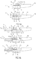
- FIGS. 1A to 1B schematically show the steps referenced 1 to 5 of the unloading process on an evacuation station 6, of packages 7 previously deposited on the upper face 8 of a tray 9.
- the tray (cf. figure 2A ) has a peripheral groove 11 forming a recess or projection relative to the face 8, of width d and depth p .
- the groove 11 does not have continuous walls and that it adjoins the internal face 12 of the corresponding edge 10, but can also be more inside the plate.
- the depth p and the width d are arranged to allow the insertion of an element at an angle (wing of the deflector) which will be detailed below.
- the packages 7 positioned in any manner on the upper face 8 of the tray are brought to a reference station P 1 .
- the plate 9 has four edges of the same height, which means that the plate can be positioned on the conveyor in an undirected and / or differentiated manner.
- the plate is referenced relative to the outside, so that the load is always towards the inside of the plate relative to the groove, in order to guarantee the absence of interface with the rest of the system.
- the conveyor 14 is equipped with a stop 15 formed by a rectangular plate. vertical 16 installed parallel to the transfer direction of the conveyor 14.
- the push cylinder 13 is in turn equipped with a rod 17 terminated by a buffer 18 arranged to push the edge 19 of the plate opposite the plate according to the arrow 20, to a position 21 for locking the edge 10 for example the along a guide rail 22 at the edge of the conveyor.
- the load 7 being in height when one pushes on the plate, and that the load is badly placed, that is to say that it bites for example on the groove of the plate, there is sliding of the packages caused by the placing in contact with the packages with the plate 16.
- the plate and more precisely its lateral edge 10 then passes below the peripheral edge or lower edge 23 of the plate, to reach its final determined position, that is to say here in abutment on the rail 22.
- This position delimits a distance l (see step 3) which guarantees a longitudinal clearance between the outer peripheral side 24 of the packages and the lateral edge 10 of the tray sufficient for the packages to therefore be situated entirely outside the groove, towards the interior. of the plateau.
- the steps referenced 1 and 2 therefore made it possible to create sufficient longitudinal clearance between the packages and the edge of the plate situated on the side of the discharge of the load.
- This is for example adjustable. It corresponds to the width of the clearance necessary for the embedding of the lower wing of the deflector, between the edge of the plate and the load and is such that l > d + e or e is the width of the edge 10 proper (see figure 4A ).
- the plate 16 for example metallic, is fixed. It is of height corresponding to the highest of the loads and of length approximately equal to or greater than that of the plate with a lower edge which therefore allows the edge 10 of the plate to pass below.
- step referenced 2 the jack 13 retracts and the plate is then transferred to the station or next post P 2 , unloading, where the extraction of the packages will be able to be carried out via displacement means.
- the plate is first of all brought into the exact position opposite the discharge station P 3 by activating a stop 25 for example formed by a strip extending perpendicular to the conveyor 14 (see figure 6 ).
- the movable deflector 26 is a sheet in the form of an elongated longitudinal angle iron having a horizontal face or upper wing and an inclined face or lower wing with a slope relative to the horizontal of the '' order of 30 °, or forming an angle ⁇ between the two wings of the angle iron of the order of 150 ° ( ⁇ 10 °).
- the deflector has a lower edge defining an edge 27.
- step 3 It is actuated between a high position 28 (see step 3 dotted line) allowing the lateral edge 10 of the plate to escape and a low position 29 (see step 4) in which the edge 26 comes to be positioned in the groove or grooved area 11 of the board.
- the depth p of the groove is such that the edge 27 of the inclined face is found below the level of the bottom of the load during the transfer.
- the movement of vertical displacement of the deflector between its high position and its low position is completed by an initial and / or final movement of tilting in rotation.
- the initial angle (retracted position) of the deflector is thus more acute than its value taken at the end of movement, which makes it possible to reduce the bulk of the system in the retracted position, while ensuring that the deflector has a clear path with respect to the charge if it has inadvertently moved.
- the package is pushed (step 5) via a pusher cylinder 30 provided with a piston 31 terminated by a cushion 32, for example provided with a slight protrusion 33 in the lower part, which makes it possible to apply the pushing force as low as possible, to better avoid the risk of tipping the packages.
- the plate 9 is evacuated downstream by the conveyor 14.
- the plate 9 is rectangular. It is for example made of plastic obtained by injection and comprises a bottom 35 provided with a rectangular central part 36, the surface of which forms the upper face 8 of the plate.
- the central part 36 is provided on its periphery with a recessed area 37 forming the groove 11 for the embedding of the deflector, bordered outwards by the four raised lateral edges 10, of height h relative to the surface 8 of the background.
- the bottom 35 comprising the central part 36 and the four peripheral grooves 11, is perforated, in the form of grating.
- edges 10 are rectangular, hollowed out from the inside at 40, with stiffeners 41 in a manner known per se, and are arranged to prevent the charges from leaving the surface of the tray by forming stops neither too high nor too low (for example of height h between 10 and 20 mm) to allow a good implementation of the process.
- Studs 42 for stiffening at the level of the spacers are provided.
- the height h of the peripheral edges relative to the surface 8 the width d of the groove 11 (for example between 30 and 50 mm), the thickness p of the depth of said groove between the upper face 43 of the groove bottom beams and the surface 8 of the upper face (for example between 3 and 10 mm).
- the length between the periphery 44 of the upper face 8 carrying the package and the external face 45 of the peripheral edge is equal to d + e with d width of the groove proper between periphery 44 and internal face 12 of the edge 10 and th thickness of the edge 10 itself.
- the orifices made in the bottom of the tray have the sole function of avoiding the retention of liquid generated by the automatic fire extinguishing heads (sprinkler device).
- the external face 45 of the edge 10 which is straight and arranged to cooperate with the pusher cushion 32, comprises visual means 46 (bar code for example) allowing the location and monitoring of the trays throughout the process.
- conveyor 14 is formed of motorized rollers 48 known in themselves.
- the cylinders 13 and 30 are in turn and for example pneumatic cylinders and the cushion 32 is advantageously surmounted by a thin plate B, slightly biased, flexible, for retaining the packages to avoid any tilting if necessary.
- the system comprises means M for moving the angle iron 26 vertically and in tilting.
- This comprises a horizontal rectangular wing 49 fixed to a beam 50 secured to the chassis 51 of the station P 3 .
- the beam 50 is fixed at each of its ends 52 to two posts 53 provided with motor means 54 for vertical actuation (jacks) and in rotation about an axis 55 by pivoting, for example with cam (not shown).
- the angle iron 26 comprises a second rectangular wing 56 integral with and forming the angle ⁇ of the order of 150 ° with the first wing and is arranged to come to be embedded in the groove 11, then allowing the sliding and the lifting of the loads according to arrow 57 during extraction, as described above.
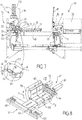
- the figure 8 shows the supply and unloading system 47 for transferring packages upstream from the evacuation station P 3 before further processing.
- This comprises a belt or conveyor 58, possibly mounted in a manner known in itself on a hoop 59 rocking between two positions perpendicular to one another, so as to allow, if necessary, the turning of the package (arrow F).
- the conveyor 58 (arrow 60) then brings the packages to the device 61 for separating the packages on either side, by pushing means 62, towards two symmetrical stations 63 for later picking up of the packages for example, by automated grippers. .
- the packages 7 were first of all placed on trays 9 randomly. They consist of products of different shapes, whose centers of gravity are more or less high.
- bottles packs are, for example, bottles packs, detergent boxes, etc.
- the trays then arrive successively at the P 1 cropping station according to a time diagram programmed as a function of requirements, so as to be within the reach of those skilled in the art.
- the plate is then immobilized at station P 1, for example by stopping the conveyor.
- the plate 9 is then pushed into abutment against the rail 22 using the pusher cylinder 13.
- the plate 16 here plays a role of blocking the packages and keeps them if necessary outside the groove 11.
- the tray leaves the space in front of the plate 16 and comes to position at the station P 2 , located opposite the station P 3 by blocking the discharge strip 25.
- the angle iron 26 is lowered, previously raised so as to allow the edge of the tray to pass underneath.
- the angle is then slightly pivoted, lowered and then placed in the groove 11 opposite.
- the jack 30 is actuated and pushes the products onto the angle iron. These rise under the effect of pressure before being placed (see step 5 of the figure 1B ) on the recovery conveyor of post P 3 (6 or 58).
- the present invention is not limited to the embodiments more particularly described. On the contrary, it embraces all of the variants, and in particular those where other means of jogging / blocking of the packages are provided in the reference position necessary for proper positioning of the products and their raising along the angle 26 .
Description
La présente invention concerne un procédé de déchargement sur un poste d'évacuation, de colis préalablement disposés sur la face supérieure d'un plateau présentant des bords latéraux relevés.The present invention relates to a method of unloading on an evacuation station, packages previously arranged on the upper face of a tray having raised lateral edges.
Elle concerne également un système de déchargement de colis mettant en œuvre un tel procédé.It also relates to a package unloading system implementing such a process.
Elle trouve une application particulièrement importante bien que non exclusive dans le domaine des machines pour tri de colis permettant d'extraire automatiquement des charges de forme quelconque à partir d'un plateau sur lequel elles ont été placées au préalable.It finds a particularly important, although not exclusive, application in the field of parcel sorting machines making it possible to automatically extract loads of any shape from a tray on which they have been placed beforehand.
Il est connu de stocker des charges sur des plateaux avant réarrangement de celles-ci sur une palette pour transfert vers un lieu de distribution, comme une grande surface par exemple.It is known to store loads on trays before rearranging them on a pallet for transfer to a distribution place, such as a large area for example.
Le stockage sur des plateaux facilite leur rangement ordonné sur des rayonnages et leur reprise en automatique pour traitement ultérieur.Storage on trays facilitates their orderly storage on shelves and their automatic resumption for further processing.
De tels stockages sur plateaux présentent cependant un important inconvénient, à savoir celui du déchargement automatique à grande vitesse de tels plateaux.Such storage on trays, however, has a significant drawback, namely that of automatic unloading at high speed of such trays.
On connaît par exemple (
On peut également citer le document
Le document
Le document
On connaît aussi des systèmes mettant en œuvre des plateaux à trous au travers desquels on vient repousser les colis dans une position d'extraction Ici encore il est nécessaire de prévoir des moyens ajustés mécaniquement de façon précise, nécessitant des plateaux spécialement conçus avec un grand nombre de trous espacés régulièrement sur toute la surface du plateau, les trous étant ici conçus pour être traversés de façon escamotable par des plots permettant ainsi le soulèvement des colis situés au-dessus des trous et leur extraction.There are also known systems using trays with holes through which the packages are pushed back into an extraction position Here again it is necessary to provide means that are mechanically adjusted precisely, requiring specially designed trays with a large number holes regularly spaced over the entire surface of the plate, the holes here being designed to be retractably crossed by studs thus allowing the lifting of the packages located above the holes and their extraction.
De tels systèmes présentent plusieurs inconvénients notamment dès que les colis ne sont pas de forme régulière et/ou présentent une forme instable.Such systems have several drawbacks, especially when the packages are not of regular shape and / or have an unstable shape.
La présente invention vise à pallier ces inconvénients en proposant un procédé selon la revendication 1 et un système de déchargement selon la revenidcation 9 répondant mieux que ceux antérieurement connus aux exigences de la pratique, notamment en ce qu'elle autorise le déchargement de colis de formes multiples, non nécessairement parallélépipédiques, présentant un fond irrégulier non plan et/ou présentant un centre de gravité élevé générateur d'instabilité et ce avec des vitesses de traitement supérieures à 1 000 colis par heure.The present invention seeks to overcome these drawbacks by proposing a method according to
Dans ce but l'invention propose un procédé de déchargement selon la revendication 1 sur un poste d'évacuation de colis préalablement déposés sur la face supérieure d'au moins un plateau présentant au moins un bord latéral relevé, caractérisé en ce le plateau comportant une rainure périphérique jouxtant ledit bord, on place le plateau sur un convoyeur avec ledit bord latéral du côté du poste d'évacuation, on règle la position relative des colis par rapport au plateau pour que les colis soient situés sur la face supérieure du plateau entièrement à l'extérieur de ladite rainure, on déplace le plateau devant le poste d'évacuation équipé à sa jonction avec le convoyeur d'un déflecteur mobile en forme de cornière présentant une aile inclinée vers le bas d'un angle α, ledit déflecteur étant en position haute permettant d'échapper le bord latéral du plateau, on déplace ledit déflecteur vers une position basse de sorte que l'arête de l'aile inclinée vienne s'encastrer dans ladite rainure en dessous de la face supérieure du plateau et on pousse les colis latéralement sur le déflecteur jusqu'à complet transfert sur ledit poste d'évacuation.For this purpose, the invention provides an unloading method according to
Le procédé et le système qu'il utilise permettent ainsi de prendre en charge des colis positionnés de manière quelconque sur le plateau, et ce indépendamment de leur instabilité.The method and the system which it uses thus make it possible to take care of packages positioned in any manner on the platform, and this independently of their instability.
La première opération que ce procédé met en œuvre est en effet de référencer en dynamique le plateau selon un guide opposé au sens d'évacuation. La position des colis étant incertaine, cette opération permet de les placer sur le plateau en garantissant l'absence d'interférence entre la charge et le dispositif déflecteur qui, après abaissement, autorise alors le déchargement des colis indépendamment de leur stabilité du fait notamment du poussage.The first operation that this process implements is in fact to dynamically reference the plate according to a guide opposite to the direction of evacuation. The position of the packages being uncertain, this operation makes it possible to place them on the pan, guaranteeing the absence of interference between the load and the deflector device which, after lowering, then authorizes the unloading of the packages regardless of their stability due in particular to the pushing.
Dans des modes de réalisation avantageux, on a par ailleurs et/ou de plus recours à l'une et/ou à l'autre des dispositions suivantes :
- on décharge successivement plusieurs plateaux, le transfert des colis d'un premier plateau sur le poste d'évacuation s'effectuant pendant le règlement de la position relative des colis sur un deuxième plateau préalablement placé à la suite du premier sur le convoyeur et ainsi de suite pour les plateaux suivants ;
- pour régler la position relative des colis par rapport au plateau, le convoyeur étant équipé d'une butée située du côté du poste d'évacuation, on référencie en dynamique le plateau du côté opposé à la butée, pour garantir l'absence d'interférence entre les colis et ladite butée, et on repousse le plateau vers la butée par le biais d'un actionneur mécanique en extension jusqu'à une position finale déterminée, pour provoquer s'il y a lieu le glissement des colis sur le plateau occasionné par la mise en contact des colis avec la butée tout en garantissant ainsi un jeu longitudinal entre les colis et le bord latéral du plateau suffisant pour que lesdits colis soient entièrement situés à l'extérieur de la rainure en position finale ;
- on détecte la position finale déterminée du plateau, ladite détection provoquant le retrait de l'actionneur et le transfert du plateau en vis à vis du poste d'évacuation ;
- on déplace le déflecteur entre sa positon haute et sa position basse, et inversement, par un mouvement vertical complété par un mouvement initial et/ou final de basculement en rotation, de façon à réduire l'encombrement et permettre un dégagement accru de la cornière vis à vis du plateau et des colis qu'il supporte ;
- l'angle α est compris entre 140° et 170 ;
- l'angle α est de l'ordre de 150°;
- d ≥ h/tg β, avec β = 180° - α, h étant la hauteur du bord par rapport à la face supérieure du plateau, et d la largeur de la rainure périphérique.
- several trays are successively unloaded, the transfer of the packages from a first tray to the evacuation station being carried out during the settlement of the relative position of the packages on a second tray previously placed after the first on the conveyor and so on. suite for the following trays;
- to adjust the relative position of the packages relative to the platform, the conveyor being equipped with a stop located on the side of the evacuation station, the platform is dynamically referenced on the side opposite to the stop, to guarantee the absence of interference between the packages and said stopper, and the tray is pushed back towards the stopper by means of a mechanical actuator in extension to a determined final position, to cause the packages to slide on the tray if necessary bringing the packages into contact with the stop while thus ensuring a longitudinal clearance between the packages and the lateral edge of the plate sufficient for said packages to be entirely located outside the groove in the final position;
- the determined final position of the plate is detected, said detection causing the withdrawal of the actuator and the transfer of the plate opposite the evacuation station;
- the deflector is moved between its upper position and its lower position, and vice versa, by a vertical movement supplemented by an initial and / or final tilting movement in rotation, so as to reduce the bulk and allow increased clearance of the screw angle opposite the tray and the packages it supports;
- the angle α is between 140 ° and 170;
- the angle α is of the order of 150 °;
- d ≥ h / tg β, with β = 180 ° - α, h being the height of the edge relative to the upper face of the plate, and d the width of the peripheral groove.
L'invention propose également un système mettant en œuvre le procédé tel que décrit ci-avant.The invention also provides a system implementing the method as described above.
Elle propose un système de déchargement selon la revendication 9 sur un poste d'évacuation de colis comprenant au moins un plateau comportant une face supérieure de support de colis et présentant au moins un bord latéral relevé, caractérisé
en ce que le plateau comporte une rainure périphérique de largeur d et de profondeur p, jouxtant ledit bord,
en ce que le système comporte de plus
un convoyeur agencé pour transférer le plateau avec son bord latéral situé du côté du poste d'évacuation vers une position en vis à vis dudit poste d'évacuation,
des premiers moyens actionneurs du déplacement transversal du plateau en dynamique,
des moyens de butée latérale du plateau du côté du poste d'évacuation, les dits premiers moyens actionneurs et lesdits moyens de butée étant agencés pour régler la position relative des colis par rapport au plateau pour que les colis soient toujours situés sur la face supérieure du plateau entièrement à l'extérieur de ladite rainure,
ledit convoyeur étant agencé pour déplacer ensuite le plateau devant le poste d'évacuation,
un déflecteur mobile situé à la jonction entre le poste d'évacuation et le convoyeur, ledit réflecteur étant en forme de cornière présentant une aile inclinée vers le bas d'un angle α,
des moyens de déplacement de ladite cornière entre une position haute permettant d'échapper le bord latéral du plateau, et une position basse agencés pour permettre l'encastrement de l'arête de l'aile inclinée dans ladite rainure en dessous de la face supérieure du plateau et
des moyens de poussée agencés pour pousser les colis latéralement sur le déflecteur jusqu'à complet transfert sur ledit poste d'évacuation.It proposes an unloading system according to
in that the plate has a peripheral groove of width d and depth p , adjoining said edge,
in that the system also has
a conveyor arranged to transfer the tray with its lateral edge situated on the side of the evacuation station towards a position opposite said evacuation station,
first actuator means for the transverse movement of the plate in dynamics,
lateral stop means of the plate on the side of the evacuation station, said first actuator means and said stop means being arranged to adjust the relative position of the packages relative to the plate so that the packages are always located on the upper face of the plate entirely outside of said groove,
said conveyor being arranged to then move the tray in front of the evacuation station,
a movable deflector situated at the junction between the evacuation station and the conveyor, said reflector being in the form of an angle iron having a wing inclined downwards by an angle α,
means for moving said angle between a high position allowing the lateral edge of the plate to escape, and a low position arranged to allow the edge of the inclined wing to be embedded in said groove below the upper face of the tray and
pushing means arranged to push the packages laterally on the deflector until complete transfer to said evacuation station.
Pour ce faire les dimensions de la cornière et plus particulièrement de la largeur et de l'angle α de son aile inclinée par rapport à la ligne de jonction avec l'aile fixe de la cornière solidaire du poste d'évacuation, sont adaptées à la hauteur et la profondeur de la rainure de façon à la portée de l'homme du métier.To do this, the dimensions of the angle iron and more particularly of the width and of the angle α of its inclined wing relative to the junction line with the fixed wing of the angle iron secured to the evacuation station, are adapted to the height and depth of the groove within reach of the skilled person.
Avantageusement le système est caractérisé en ce que la butée est une plaque verticale rectangulaire fixe, de hauteur déterminée, de longueur égale ou sensiblement égale à celle du plateau, présentant un bord inférieur situé à une distance e, par rapport à la face supérieure du convoyeur, supérieure à la hauteur du plateau.Advantageously, the system is characterized in that the stop is a fixed rectangular vertical plate, of determined height, of equal length or substantially equal to that of the tray, having a lower edge located at a distance e , relative to the upper face of the conveyor, greater than the height of the tray.
Dans un mode de réalisation avantageux les moyens de déplacement de la cornière entre sa positon haute et sa position basse comprennent des moyens d'actionnement vertical de la cornière et des moyens de basculement en rotation de ladite cornière (autour d'un axe parallèle au plateau, c'est à dire perpendiculaire au sens d'évacuation des colis), de façon à réduire l'encombrement et permettre un dégagement accru de la cornière vis à vis du plateau et des colis qu'il supporte.In an advantageous embodiment, the means of displacement of the angle iron between its high position and its low position comprise means for vertically actuating the angle iron and means for tilting said angle angle in rotation (around an axis parallel to the plate , that is to say perpendicular to the direction of evacuation of the packages), so as to reduce the bulk and allow increased clearance of the angle iron with respect to the plate and the packages that it supports.
Egalement avantageusement l'angle α est compris entre 140° et 170°, l'angle α étant par exemple égal ou de l'ordre de 150°, et/ou avec d ≥ h/tg (180° - α).Also advantageously the angle α is between 140 ° and 170 °, the angle α being for example equal to or of the order of 150 °, and / or with d ≥ h / tg (180 ° - α).
Avantageusement le plateau est ajouré par des orifices régulièrement répartis, ce qui permet l'évacuation de l'eau et/ou des liquides qui seraient déversés sur les plateaux.Advantageously, the plate is perforated by regularly distributed orifices, which allows the evacuation of water and / or liquids which would be poured onto the plates.
L'invention sera mieux comprise à la lecture des modes de réalisation décrits ci-après de façon non limitative en référence aux figures qui l'accompagnent et dans lesquelles :
- Les
figures 1A et 1B illustrent schématiquement les étapes du procédé de déchargement selon un mode de réalisation de l'invention. - Les
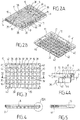
figures 2A et 2B sont des vues en perspective de dessus et de dessous d'un mode de réalisation de plateau utilisable avec le procédé selon l'invention. - La
figure 3 est une vue en plan par le dessous, du plateau de lafigure 2B . - La
figure 4 est la vue en coupe latérale selon IV-IV de lafigure 3 . - La
figure 4A est un détail agrandi du bord du plateau de lafigure 4 , montrant la rainure. - La
figure 5 est une vue latérale du plateau de lafigure 2A . - La
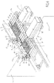
figure 6 est une vue en perspective d'un mode de réalisation du système de déchargement selon l'invention. - La
figure 7 est une vue en coupe latérale selon VII-VII de lafigure 6 . - La
figure 8 montre en perspective et schématiquement, un exemple d'agencement du système de lafigure 6 avec les postes suivants de traitement de colis.
- The
Figures 1A and 1B schematically illustrate the steps of the unloading method according to an embodiment of the invention. - The
Figures 2A and 2B are perspective views from above and from below of an embodiment of a tray usable with the method according to the invention. - The
figure 3 is a plan view from below, of the plateau of thefigure 2B . - The
figure 4 is the side section view according to IV-IV of thefigure 3 . - The
figure 4A is an enlarged detail of the edge of the tray of thefigure 4 , showing the groove. - The
figure 5 is a side view of the tray of thefigure 2A . - The
figure 6 is a perspective view of an embodiment of the unloading system according to the invention. - The
figure 7 is a side section view according to VII-VII of thefigure 6 . - The
figure 8 shows in perspective and schematically, an example of arrangement of the system of thefigure 6 with the following parcel processing stations.
Les
Le plateau 9 comporte quatre bords latéraux 10 relevés, présentant une hauteur h par rapport à la face supérieure 8 par exemple h = 2 cm.The
Le plateau (cf.
On notera que sur les
La profondeur p et la largeur d sont agencées pour permettre l'insertion d'un élément en biais (aile du déflecteur) qui sera détaillé ci-après.The depth p and the width d are arranged to allow the insertion of an element at an angle (wing of the deflector) which will be detailed below.
En référence à l'étape 1, les colis 7 positionnés de manière quelconque sur la face supérieure 8 du plateau, sont amenés à un poste P1 de référencement. Celui-ci fait face à un vérin pousseur 13, le plateau étant amené par un convoyeur 14, par exemple formé par un tapis ou un ensemble de rouleaux connus en eux-mêmes, le bord de hauteur h du plateau étant situé du côté opposé au vérin 13.With reference to step 1, the
Dans le mode de réalisation qui sera détaillé ci-après le plateau 9 a quatre bords de même hauteur ce qui fait que le plateau peut être positionné sur le convoyeur de façon non orientée et/ou différenciée.In the embodiment which will be detailed below, the
Lors de cette étape 1, le plateau est référencé par rapport à l'extérieur, pour que la charge soit toujours vers l'intérieur du plateau par rapport à la rainure, dans le but de garantir l'absence d'interface avec la suite du système.During this
En d'autres termes et pour que la charge soit toujours du bon côté de la rainure, on va régler ici la position relative des colis 7 par rapport au plateau 9.In other words and so that the load is always on the right side of the groove, we will adjust here the relative position of the
Pour ce faire le convoyeur 14 est équipé d'une butée 15 formée par une plaque rectangulaire verticale 16 installée parallèlement au sens de transfert du convoyeur 14.To do this, the
Le vérin pousseur 13 est quant à lui équipé d'une tige 17 terminée par un tampon 18 agencé pour repousser le bord 19 du plateau opposé à la plaque selon la flèche 20, jusqu'à une position 21 de blocage du bord 10 par exemple le long d'un rail de guidage 22 en bordure du convoyeur.The
La charge 7 étant en hauteur lorsque l'on pousse sur le plateau, et que la charge est mal placée, c'est à dire qu'elle mord par exemple sur la rainure du plateau, il y a glissement des colis occasionné par la mise en contact des colis avec la plaque 16.The
Le plateau et plus précisément son bord latéral 10 passe alors en dessous du bord périphérique ou chant inférieur 23 de la plaque, pour atteindre sa position finale déterminée, c'est à dire ici en butée sur le rail 22.The plate and more precisely its
Cette position délimite une distance l (voir étape 3) qui garantit un jeu longitudinal entre le côté périphérique extérieur 24 des colis et le bord latéral 10 du plateau suffisant pour que les colis soient donc situés entièrement en dehors de la rainure, vers l'intérieur du plateau.This position delimits a distance l (see step 3) which guarantees a longitudinal clearance between the outer
Les étapes référencées 1 et 2 ont donc permis de créer un jeu longitudinal suffisant entre les colis et le bord du plateau situé du côté de l'évacuation de la charge.The steps referenced 1 and 2 therefore made it possible to create sufficient longitudinal clearance between the packages and the edge of the plate situated on the side of the discharge of the load.
Celui-ci est par exemple réglable. Il correspond à la largeur du jeu nécessaire pour l'encastrement de l'aile inférieure du déflecteur, entre le bord du plateau et la charge et est tel que l > d + e ou e est la largeur du bord 10 proprement dit (voir
La plaque 16 par exemple métallique est fixe. Elle est de hauteur correspondant à la plus haute des charges et de longueur approximativement égale ou supérieure à celle du plateau avec un chant inférieur qui laisse donc passer par en dessous le bord 10 du plateau.The
Une fois le glissement relatif des colis effectué (voir étape référencée 2), par exemple détecté par la venue en butée finale du bord opposé 23 du plateau sur le rail 22, le vérin 13 se rétracte et le plateau est alors transféré à la station ou poste suivant P2, de déchargement, où l'extraction des colis va pouvoir s'effectuer via des moyens de déplacement.Once the relative sliding of the packages has been carried out (see step referenced 2), for example detected by the coming into final abutment of the
Le plateau est tout d'abord amené en position exacte en vis à vis du poste d'évacuation P3 grâce à l'activation d'une butée 25 par exemple formée par une réglette s'étendant perpendiculairement au convoyeur 14 (voir
On vient alors mettre en place le déflecteur mobile 26. Il s'agit d'une tôle en forme de cornière longitudinale allongée présentant une face ou aile supérieure horizontale et une face ou aile inférieure inclinée avec une pente par rapport à l'horizontal de l'ordre de 30°, ou formant un angle α entre les deux ailes de la cornière de l'ordre de 150° (à ± 10°).We then install the
Le déflecteur présente un bord inférieur définissant une arête 27.The deflector has a lower edge defining an
Il est actionné entre une position haute 28 (voir étape 3 trait mixte) permettant d'échapper le bord latéral 10 du plateau et une position basse 29 (voir étape 4) dans laquelle l'arête 26 vient se positionner dans la rainure ou zone rainurée 11 du plateau.It is actuated between a high position 28 (see
Ceci permet d'éviter toute discontinuité entre le plan 8 du plateau 9 sur lequel repose la charge 7 et le déflecteur 26.This avoids any discontinuity between the
La profondeur p de la rainure est telle que l'arête 27 du pan incliné se retrouve sous le niveau du fond de la charge lors du transfert.The depth p of the groove is such that the
Dans le mode de réalisation plus particulièrement décrit ici on complète le mouvement de déplacement vertical du déflecteur entre sa position haute et sa position basse, par un mouvement initial et/ou final de basculement en rotation.In the embodiment more particularly described here, the movement of vertical displacement of the deflector between its high position and its low position is completed by an initial and / or final movement of tilting in rotation.
L'angle initial (position rentrée) du déflecteur est ainsi plus aigu que sa valeur prise en fin de mouvement, ce qui permet de réduire l'encombrement du système en position rentrée, tout en assurant au déflecteur une trajectoire dégageante vis à vis de la charge si par inadvertance celle-ci s'était déplacée.The initial angle (retracted position) of the deflector is thus more acute than its value taken at the end of movement, which makes it possible to reduce the bulk of the system in the retracted position, while ensuring that the deflector has a clear path with respect to the charge if it has inadvertently moved.
Une fois le déflecteur en position, on pousse (étape 5) le colis via un vérin pousseur 30 muni d'un piston 31 terminé par un coussin 32, par exemple muni d'une légère excroissance 33 en partie basse, ce qui permet d'appliquer l'effort de poussée aussi bas que possible, pour mieux éviter les risques de basculement des colis.Once the deflector in position, the package is pushed (step 5) via a
Ceux-ci glissent sur le déflecteur, en remontant la pente, pour prendre position au poste P3, sur le convoyeur connu en lui-même.These slide on the deflector, going up the slope, to take position at position P 3 , on the conveyor known in itself.
Le plateau 9 est quant à lui évacué en aval par le convoyeur 14.The
On va maintenant décrire en référence aux
Le plateau 9 est rectangulaire. Il est par exemple en matière plastique obtenu par injection et comprend un fond 35 muni d'une partie centrale rectangulaire 36 dont la surface forme la face supérieure 8 du plateau.The
La partie centrale 36 est munie sur sa périphérie d'une zone en retrait 37 formant la rainure 11 pour l'encastrement du déflecteur, bordée vers l'extérieur par les quatre bords latéraux relevés 10, de hauteur h par rapport à la surface 8 du fond.The central part 36 is provided on its periphery with a recessed area 37 forming the
Dans ce mode de réalisation, le fond 35 comprenant la partie centrale 36 et les quatre rainures périphériques 11, est ajouré, en forme de caillebotis.In this embodiment, the bottom 35 comprising the central part 36 and the four
Il est formé de traverses ou poutres 38 qui s'entrecroisent régulièrement, en laissant entre elles des orifices rectangulaires 39 qui vont permettre la vidange automatique du fond du plateau en évitant toute rétention d'eau.It is formed of crossbeams or
Plus précisément les bords 10 sont rectangulaires, évidés de l'intérieur en 40, avec des raidisseurs 41 de façon connue en elle-même, et sont agencés pour empêcher les charges de sortir de la surface du plateau en formant des butées ni trop hautes ni trop basses (par exemple de hauteur h comprise entre 10 et 20 mm) pour permettre une bonne mise en œuvre du procédé.More precisely, the
Des plots 42 de rigidification au niveau des entretoises sont prévus.
En référence à la
La longueur entre la périphérie 44 de la face supérieure 8 porteuse de colis et la face externe 45 du bord périphérique est égale à d + e avec d largeur de la rainure proprement dite entre périphérie 44 et face interne 12 du bord 10 et e épaisseur du bord 10 lui-même.The length between the
Plus précisément le plateau pouvant être assimilé à une plaque à bords relevés de hauteur déterminée, le choix de la hauteur choisie est, en fait, un compromis qui doit satisfaire à deux contraintes antinomiques :
- La hauteur de bord (profondeur inférieure ≈ 20 mm) doit être suffisamment importante pour éviter que la charge transportée quitte le plateau lors de son immobilisation (rôle de garde en fin de transfert).
- La hauteur doit être « limitée » car cette dimension impacte directement le taux de remplissage du plateau, défini comme le rapport de la base de la plus grande des charges à transporter sur la face interne du plateau. Idéalement se rapport
doit tendre vers 1.
- The edge height (lower depth ≈ 20 mm) must be large enough to prevent the transported load from leaving the platform when it is immobilized (guard role at the end of transfer).
- The height must be "limited" because this dimension directly impacts the filling rate of the tray, defined as the ratio of the base of the greater loads to be transported on the internal face of the tray. Ideally this ratio should tend towards 1.
Considérons β = 30° (= 180° - α) comme étant l'angle de déflection,
si h = 20 mm (côté intérieur) est la hauteur à franchir pour extraire la charge du plateau, alors d (dimension correspondant à la largeur de la rainure, devant restée libre quelques soient les dimensions de la charge transportée) doit satisfaire à la relation : ![]()
if h = 20 mm (inner side) is the height to be crossed to extract the load from the platform, then d (dimension corresponding to the width of the groove, in front of it remaining free whatever the dimensions of the load transported) must satisfy the relation : ![]()
Dans un exemple de réalisation on choisit d = 40 mm, et on prévoit deux formats de plateaux rectangulaires (dans le but d'adapter au mieux les dimensions des charges transportées au plateau) et deux rainures latérales. Aussi et par exemple, dans le cas de grands plateaux (par exemple Dim. Ext = 660 x 460 mm2) les deux rainures sont réalisées suivant le grand côté des rectangles. Dans le cas de plus petits plateaux (Dim. Ext = 460 x 330 mm2) les rainures sont par contre réalisées suivant le petit côté.In an exemplary embodiment, d = 40 mm is chosen, and two rectangular tray formats are provided (in order to best adapt the dimensions of the loads transported to the tray) and two lateral grooves. Also and for example, in the case of large plates (for example Dim. Ext = 660 x 460 mm 2 ) the two grooves are made along the long side of the rectangles. In the case of smaller plates (Dim. Ext = 460 x 330 mm 2 ) the grooves are however made along the short side.
A noter que les orifices pratiqués dans le fond du plateau ont pour seule fonction d'éviter la rétention de liquide généré par les têtes d'extinction automatique d'incendie (dispositif de sprinklage).Note that the orifices made in the bottom of the tray have the sole function of avoiding the retention of liquid generated by the automatic fire extinguishing heads (sprinkler device).
Avantageusement, la face externe 45 du bord 10, qui est droite et agencée pour coopérer avec le coussin pousseur 32, comporte des moyens visuels 46 (code barre par exemple) permettant le repérage et le suivi des plateaux tout au long du procédé.Advantageously, the
On a représenté sur les
Ici le convoyeur 14 est formé de rouleaux motorisés 48 connus en eux-mêmes.Here the
Les vérins 13 et 30 sont quant à eux et par exemple des vérins pneumatiques et le coussin 32 est avantageusement surmonté d'une plaque B fine, en léger biais, flexible, de rétention des colis pour éviter tout basculement s'il y avait lieu.The
Selon l'invention plus particulièrement décrite ici, le système comprend des moyens M de déplacement de la cornière 26 verticalement et en basculement.According to the invention more particularly described here, the system comprises means M for moving the
Celle-ci comprend une aile rectangulaire 49 horizontale fixée sur une poutre 50 solidaire du châssis 51 du poste P3.This comprises a horizontal
La poutre 50 est fixée à chacune de ses extrémités 52 à deux poteaux 53 munis de moyens moteurs 54 d'actionnement en vertical (vérins) et en rotation autour d'un axe 55 par pivotement par exemple à came (non représentée).The
La cornière 26 comprend une deuxième aile rectangulaire 56 solidaire et formant l'angle α de l'ordre de 150° avec la première aile et est agencée pour venir s'encastrer dans la rainure 11, autorisant alors le glissement et la remontée des charges selon la flèche 57 lors de l'extraction, comme décrit précédemment.The
Il est prévu, si nécessaire dans le cas de l'utilisation de plateaux de longueurs différentes, et en fonction des longueurs des plateaux, une fente P permettant le passage du bord orthogonal 10 du plateau le plus petit.It is provided, if necessary in the case of the use of trays of different lengths, and depending on the lengths of the trays, a slot P allowing the passage of the
La
Celui-ci comprend un tapis ou convoyeur 58, éventuellement monté de façon connue en elle-même sur un arceau 59 basculant entre deux positions perpendiculaires l'une de l'autre, de façon à permettre s'il y a lieu, le retournement des colis (flèche F).This comprises a belt or
Le convoyeur 58 (flèche 60) amène alors les colis au dispositif 61 de séparation des colis de part et d'autre, par des moyens pousseurs 62, vers deux postes symétriques 63 de reprise ultérieure des colis par exemple, par des pinces de préhension automatisée.The conveyor 58 (arrow 60) then brings the packages to the device 61 for separating the packages on either side, by pushing
On va maintenant décrire en référence aux
Les colis 7 ont tout d'abord été disposés sur des plateaux 9 de façon aléatoire. Ils sont constitués de produits de formes différentes, dont les centres de gravité sont plus ou moins hauts.The
Il s'agit par exemple de packs de bouteilles, de boîtes de lessive etc....These are, for example, bottles packs, detergent boxes, etc.
Les plateaux arrivent ensuite successivement au poste P1 de recadrage selon un diagramme de temps programmé en fonction des besoins, de façon à la portée de l'homme du métier.The trays then arrive successively at the P 1 cropping station according to a time diagram programmed as a function of requirements, so as to be within the reach of those skilled in the art.
Le plateau est alors immobilisé au poste P1 par exemple par l'arrêt du convoyeur.The plate is then immobilized at station P 1, for example by stopping the conveyor.
On vient ensuite pousser le plateau 9 en butée contre le rail 22 à l'aide du vérin pousseur 13.The
La plaque 16 joue ici un rôle de blocage des colis et maintient s'il y a lieu ces derniers en dehors de la rainure 11.The
Le convoyeur 14, arrêté pour permettre le positionnement des colis lors du point fixe ci-dessus, est alors redémarré.The
Le plateau, avec les colis en position de référence, quitte l'espace en face de la plaque 16 et vient se positionner au poste P2, situé en face du poste P3 par blocage de la réglette 25 d'évacuation.The tray, with the packages in the reference position, leaves the space in front of the
Le plateau et les colis étant positionnés et cadrés le long du rail 22, on descend la cornière 26, préalablement soulevée de façon à permettre au bord du plateau de passer en dessous.The tray and the packages being positioned and aligned along the
La cornière est alors légèrement pivotée, descendue puis mise en place dans la rainure 11 en vis à vis.The angle is then slightly pivoted, lowered and then placed in the
Le vérin 30 est actionné et vient pousser les produits sur la cornière. Ceux-ci remontent sous l'effet de la pression avant de se placer (cf. étape 5 de la
Entre temps, et en temps masqué, les opérations référencées 1 et 2 ayant été effectuées pour le plateau suivant, celui-ci peut prendre la position face au vérin 30 et ainsi de suite.In the meantime, and in masked time, the operations referenced 1 and 2 having been carried out for the next plate, the latter can take the position facing the
Comme il va de soi et comme il résulte également de ce qui précède, la présente invention n'est pas limitée aux modes de réalisation plus particulièrement décrits. Elle en embrasse au contraire toutes les variantes et notamment celles où il est prévu d'autres moyens de taquage/blocage des colis dans la position de référence nécessaire à une bonne mise en place des produits et remontées de ces derniers le long de la cornière 26.As is obvious and as also follows from the above, the present invention is not limited to the embodiments more particularly described. On the contrary, it embraces all of the variants, and in particular those where other means of jogging / blocking of the packages are provided in the reference position necessary for proper positioning of the products and their raising along the
Claims (15)
- Method for unloading onto a removal station (P3) packages (7) which have previously been deposited on the upper face (8) of at least one tray (9) having at least one lateral edge (10), the tray (9) having a peripheral groove (11) adjacent to said edge, the method comprising the following steps: the tray is placed on a conveyor (14) with said lateral edge (10) on the removal station (P3) side, the relative position of the packages (7) with respect to the tray (9) is adjusted so that the packages are situated on the upper face (8) of the tray wholly outside said groove (11), the tray (9) is moved in front of the removal station (P3) equipped, at its junction with the conveyor, with a movable deflector (26) in the form of an angle-piece having a wing (56) inclined downwards at an angle α, said deflector (26) being in a top position (28) in which it is out of the way of the lateral edge (10) of the tray, said deflector (26) is moved into a bottom position (29) so that the edge (27) of the inclined wing fits into said groove (11) beneath the upper face (8) of the tray, and the packages (7) are pushed sideways onto the deflector (26) until they are transferred completely to said removal station (P3).
- Method according to claim 1, characterised in that a plurality of trays (9) are unloaded in succession, the transfer of the packages (7) from a first tray to the removal station (P3) taking place during the adjustment of the relative position of the packages on a second tray previously placed on the conveyor (14) behind the first tray, and so on for the following trays.
- Method according to any one of the preceding claims, characterised in that, in order to adjust the relative position of the packages (7) with respect to the tray (9), the conveyor (14) being equipped with a stop (15) situated on the removal station (P3) side, the tray (9) is dynamically indexed on the side opposite the stop in order to ensure the absence of interference between the packages and said stop, and the tray (9) is pushed towards the stop (15) by way of an extending mechanical actuator (13) to a given final position, in order to cause, if necessary, the packages to slide on the tray as a result of contact of the packages (7) with the stop (15), thus ensuring a sufficient longitudinal play between the packages and the lateral edge (10) of the tray that said packages are situated wholly outside the groove (11) in the final position.
- Method according to claim 3, characterised in that the given final position of the tray (9) is detected, said detection causing the actuator to be retracted and the tray to be transferred opposite the removal station (P3).
- Method according to any one of the preceding claims, characterised in that the deflector (26) is displaced between its top position (28) and its bottom position (29), and vice versa, by a vertical movement combined with an initial and/or final tilt and turn movement, so as to reduce the space required and permit an increased clearance of the angle-piece (26) relative to the tray and the packages which it supports.
- Method according to any one of the preceding claims, characterised in that the angle α is between 140° and 170°.
- Method according to claim 3, characterised in that the angle α is approximately 150°.
- Method according to any one of the preceding claims, characterised in that, h being the height of the edge relative to the upper face of the tray, and d the width of the peripheral groove, d ≥ h/tg β, where β = 180° - α.
- System (47) for unloading packages (7) onto a removal station (P3), comprising at least one tray (9) having an upper face (8) for supporting packages and having at least one raised lateral edge (10) of height h,
the tray (9) having a peripheral groove (11) of width d and depth p, adjacent to said edge,
the system (47) further comprisinga conveyor (14) arranged to transfer the tray (9) with its lateral edge (10) situated on the removal station (P3) side to a position opposite said removal station,first actuating means (13) for the dynamic transverse displacement of the tray (9),stop means (15) for the tray on the removal station side,
said first actuating means (13) and said stop means (15) being arranged to adjust the relative position of the packages with respect to the tray so that the packages (7) are always situated on the upper face (8) of the tray wholly outside said groove (11),said conveyor (14) being arranged to subsequently displace the tray in front of the removal station,a movable deflector (26) situated at the junction between the removal station (P3) and the conveyor (14), said deflector (26) being in the form of an angle-piece having a wing (56) inclined downwards at an angle α,means (M) for displacing said angle-piece between a top position (28) in which it is out of the way of the lateral edge (10) of the tray and a bottom position (29) arranged to allow the edge (27) of the inclined wing to fit into said groove beneath the upper face (8) of the tray, andpushing means (30) arranged to push packages sideways onto the deflector (26) until they are transferred completely to said removal station. - System according to claim 9, characterised in that the stop (15) is a fixed vertical rectangular plate (16) having a given height H, having a length equal to or substantially equal to that of the tray (9) having a lower edge (23) situated at a distance e relative to the upper face of the conveyor which is greater than the height of the tray.
- System according to either claim 9 or claim 10, characterised in that the means for displacing the angle-piece (26) between its top position (28) and its bottom position (29) comprise means (M) for vertical actuation of the angle-piece and means for tilting and turning said angle-piece, so as to reduce the space required and permit an increased clearance of the angle-piece relative to the tray and the packages which it supports.
- System according to any one of claims 9 to 11, characterised in that the angle α is between 140° and 170°.
- System according to claim 12, characterised in that the angle α is approximately 150°.
- System according to any one of claims 9 to 13, characterised in that:
 where d: width of the groove,h: height of the edge relative to the upper face of the tray, and β = 180° - α.
 - System according to any one of claims 9 to 14, characterised in that the tray (9) is perforated with evenly distributed orifices (39).
Applications Claiming Priority (2)
| Application Number | Priority Date | Filing Date | Title |
|---|---|---|---|
| FR1551006A FR3032441B1 (en) | 2015-02-09 | 2015-02-09 | METHOD AND SYSTEM FOR DISCHARGING PARCELS |
| PCT/FR2016/050267 WO2016128662A1 (en) | 2015-02-09 | 2016-02-08 | Method and system for unloading a package |
Publications (2)
| Publication Number | Publication Date |
|---|---|
| EP3256409A1 EP3256409A1 (en) | 2017-12-20 |
| EP3256409B1 true EP3256409B1 (en) | 2020-04-15 |
Family
ID=53269668
Family Applications (1)
| Application Number | Title | Priority Date | Filing Date |
|---|---|---|---|
| EP16707879.9A Active EP3256409B1 (en) | 2015-02-09 | 2016-02-08 | Method and system for unloading a package |
Country Status (4)
| Country | Link |
|---|---|
| EP (1) | EP3256409B1 (en) |
| ES (1) | ES2789398T3 (en) |
| FR (1) | FR3032441B1 (en) |
| WO (1) | WO2016128662A1 (en) |
Cited By (1)
| Publication number | Priority date | Publication date | Assignee | Title |
|---|---|---|---|---|
| CN111439568A (en) * | 2020-04-28 | 2020-07-24 | 刘佳露 | Logistics package distribution equipment |
Families Citing this family (5)
| Publication number | Priority date | Publication date | Assignee | Title |
|---|---|---|---|---|
| CN106925527B (en) * | 2017-03-07 | 2023-04-11 | 顺丰速运有限公司 | Automatic cargo sorting device and using method thereof |
| CN109911522A (en) * | 2019-04-10 | 2019-06-21 | 江思琼 | A kind of carton carriage with transfer device |
| FR3118013B1 (en) * | 2020-12-21 | 2022-12-02 | Fives Syleps | ARTICLE TRANSFER SYSTEM |
| CN114633999B (en) * | 2022-05-20 | 2022-08-02 | 百信信息技术有限公司 | Automatic feeding system of server detection system |
| CN115028502A (en) * | 2022-06-29 | 2022-09-09 | 重庆长江电工工业集团有限公司 | Pipe shell tray |
Family Cites Families (6)
| Publication number | Priority date | Publication date | Assignee | Title |
|---|---|---|---|---|
| US4646629A (en) * | 1984-02-10 | 1987-03-03 | Fmc Corporation | Sterilizing apparatus |
| FR2567425B1 (en) | 1984-07-16 | 1987-06-05 | Gallet Sa | MACHINE FOR SORTING PACKAGES |
| DE9211139U1 (en) * | 1992-08-20 | 1992-10-29 | Christ, Ferdinand, 6761 Weitersweiler, De | |
| DE10313577B4 (en) * | 2003-03-26 | 2009-01-08 | Witron Logistik + Informatik Gmbh | Automated system and method for storing and picking articles |
| DE102009008155A1 (en) * | 2009-02-09 | 2010-08-19 | SSI Schäfer PEEM GmbH | Unloading station for automated separation of a container from a loading aid |
| US20130062160A1 (en) * | 2011-09-14 | 2013-03-14 | Jeffrey J. Steinbach | Article tray and handling of articles with the tray |
-
2015
- 2015-02-09 FR FR1551006A patent/FR3032441B1/en not_active Expired - Fee Related
-
2016
- 2016-02-08 ES ES16707879T patent/ES2789398T3/en active Active
- 2016-02-08 WO PCT/FR2016/050267 patent/WO2016128662A1/en active Application Filing
- 2016-02-08 EP EP16707879.9A patent/EP3256409B1/en active Active
Non-Patent Citations (1)
| Title |
|---|
| None * |
Cited By (2)
| Publication number | Priority date | Publication date | Assignee | Title |
|---|---|---|---|---|
| CN111439568A (en) * | 2020-04-28 | 2020-07-24 | 刘佳露 | Logistics package distribution equipment |
| CN111439568B (en) * | 2020-04-28 | 2021-09-07 | 上海申雪供应链管理有限公司 | Logistics package distribution equipment |
Also Published As
| Publication number | Publication date |
|---|---|
| FR3032441A1 (en) | 2016-08-12 |
| EP3256409A1 (en) | 2017-12-20 |
| FR3032441B1 (en) | 2017-02-17 |
| WO2016128662A1 (en) | 2016-08-18 |
| ES2789398T3 (en) | 2020-10-26 |
Similar Documents
| Publication | Publication Date | Title |
|---|---|---|
| EP3256409B1 (en) | Method and system for unloading a package | |
| EP3638607B1 (en) | System for storing and transporting objects stored in the racks of a warehouse | |
| EP1701602A1 (en) | System and method for packaging a rack for computer, rack for computer and transport pallet for this rack | |
| EP2625121B1 (en) | Store for tyre casings | |
| EP3464075B1 (en) | Vibrating device for the ordered rearrangement of folding boxes in a container, discharge conveyor and method for discharging containers | |
| FR3003551A1 (en) | METHOD FOR TRANSFERRING AT LEAST ONE OBJECT FROM A CONVEYING SURFACE TO A RECEPTION SURFACE, AND SYSTEM COMPRISING MEANS FOR IMPLEMENTING SUCH A METHOD | |
| EP1427655B1 (en) | Transfer device for linear conveyor | |
| FR2563197A1 (en) | STRIPE DEVICE FOR REMOVING BATTERIES OR PACKETS DEPOSITED ON A BEARING APPARATUS | |
| EP3059191A1 (en) | Machine and method for conveying items | |
| FR2583396A1 (en) | METHOD AND DEVICE FOR LOADING IN A CONTAINER AND DISCHARGING | |
| EP0334769A1 (en) | Machine for loading and unloading articles, arranged in layers | |
| FR3060538A1 (en) | METHOD AND APPARATUS FOR SEPARATING A LINK SURROUNDING A LIASSE OF PRINTS FROM A PALLET | |
| FR2634471A1 (en) | Device for positioning and stopping objects moved on a conveyor | |
| FR3097539A1 (en) | Unloading device for boxes of grapes. | |
| EP3075686B1 (en) | System and method for rotation of products | |
| EP4015423B1 (en) | System for transferring items | |
| EP3112301B1 (en) | Installation for transferring containers that may contain a powdery material | |
| FR2792167A1 (en) | RETURN PROCESS WITH REPOSITIONING AND HOLDING OF PRODUCTS | |
| FR2499955A1 (en) | INSTALLATION FOR CENTERING, SQUARING AND LAYING LOADS | |
| FR3069230A1 (en) | INSTALLATION FOR FILLING SOFT CONTAINERS | |
| EP1309501B1 (en) | Container for transporting glass sheets | |
| CH343290A (en) | Method for loading and unloading handling pallets and apparatus for implementing this method | |
| FR2506733A1 (en) | Transferring vertically sliced load as individual horizontal slices - regularly spaced both longitudinally and laterally for uniform toasted rusks | |
| BE564933A (en) | ||
| FR2459190A2 (en) | Automatic compartment stacking conveyor - has conveyor feed and travelling hoist down one side of compartments |
Legal Events
| Date | Code | Title | Description |
|---|---|---|---|
| STAA | Information on the status of an ep patent application or granted ep patent |
Free format text: STATUS: THE INTERNATIONAL PUBLICATION HAS BEEN MADE |
|
| PUAI | Public reference made under article 153(3) epc to a published international application that has entered the european phase |
Free format text: ORIGINAL CODE: 0009012 |
|
| STAA | Information on the status of an ep patent application or granted ep patent |
Free format text: STATUS: REQUEST FOR EXAMINATION WAS MADE |
|
| 17P | Request for examination filed |
Effective date: 20170807 |
|
| AK | Designated contracting states |
Kind code of ref document: A1 Designated state(s): AL AT BE BG CH CY CZ DE DK EE ES FI FR GB GR HR HU IE IS IT LI LT LU LV MC MK MT NL NO PL PT RO RS SE SI SK SM TR |
|
| AX | Request for extension of the european patent |
Extension state: BA ME |
|
| DAV | Request for validation of the european patent (deleted) | ||
| DAX | Request for extension of the european patent (deleted) | ||
| GRAP | Despatch of communication of intention to grant a patent |
Free format text: ORIGINAL CODE: EPIDOSNIGR1 |
|
| STAA | Information on the status of an ep patent application or granted ep patent |
Free format text: STATUS: GRANT OF PATENT IS INTENDED |
|
| INTG | Intention to grant announced |
Effective date: 20191204 |
|
| GRAS | Grant fee paid |
Free format text: ORIGINAL CODE: EPIDOSNIGR3 |
|
| GRAA | (expected) grant |
Free format text: ORIGINAL CODE: 0009210 |
|
| STAA | Information on the status of an ep patent application or granted ep patent |
Free format text: STATUS: THE PATENT HAS BEEN GRANTED |
|
| AK | Designated contracting states |
Kind code of ref document: B1 Designated state(s): AL AT BE BG CH CY CZ DE DK EE ES FI FR GB GR HR HU IE IS IT LI LT LU LV MC MK MT NL NO PL PT RO RS SE SI SK SM TR |
|
| REG | Reference to a national code |
Ref country code: CH Ref legal event code: EP |
|
| REG | Reference to a national code |
Ref country code: DE Ref legal event code: R096 Ref document number: 602016034001 Country of ref document: DE |
|
| REG | Reference to a national code |
Ref country code: IE Ref legal event code: FG4D Free format text: LANGUAGE OF EP DOCUMENT: FRENCH |
|
| REG | Reference to a national code |
Ref country code: AT Ref legal event code: REF Ref document number: 1257044 Country of ref document: AT Kind code of ref document: T Effective date: 20200515 |
|
| REG | Reference to a national code |
Ref country code: NL Ref legal event code: MP Effective date: 20200415 |
|
| REG | Reference to a national code |
Ref country code: LT Ref legal event code: MG4D |
|
| REG | Reference to a national code |
Ref country code: ES Ref legal event code: FG2A Ref document number: 2789398 Country of ref document: ES Kind code of ref document: T3 Effective date: 20201026 |
|
| PG25 | Lapsed in a contracting state [announced via postgrant information from national office to epo] |
Ref country code: NL Free format text: LAPSE BECAUSE OF FAILURE TO SUBMIT A TRANSLATION OF THE DESCRIPTION OR TO PAY THE FEE WITHIN THE PRESCRIBED TIME-LIMIT Effective date: 20200415 Ref country code: FI Free format text: LAPSE BECAUSE OF FAILURE TO SUBMIT A TRANSLATION OF THE DESCRIPTION OR TO PAY THE FEE WITHIN THE PRESCRIBED TIME-LIMIT Effective date: 20200415 Ref country code: LT Free format text: LAPSE BECAUSE OF FAILURE TO SUBMIT A TRANSLATION OF THE DESCRIPTION OR TO PAY THE FEE WITHIN THE PRESCRIBED TIME-LIMIT Effective date: 20200415 Ref country code: PT Free format text: LAPSE BECAUSE OF FAILURE TO SUBMIT A TRANSLATION OF THE DESCRIPTION OR TO PAY THE FEE WITHIN THE PRESCRIBED TIME-LIMIT Effective date: 20200817 Ref country code: NO Free format text: LAPSE BECAUSE OF FAILURE TO SUBMIT A TRANSLATION OF THE DESCRIPTION OR TO PAY THE FEE WITHIN THE PRESCRIBED TIME-LIMIT Effective date: 20200715 Ref country code: GR Free format text: LAPSE BECAUSE OF FAILURE TO SUBMIT A TRANSLATION OF THE DESCRIPTION OR TO PAY THE FEE WITHIN THE PRESCRIBED TIME-LIMIT Effective date: 20200716 Ref country code: SE Free format text: LAPSE BECAUSE OF FAILURE TO SUBMIT A TRANSLATION OF THE DESCRIPTION OR TO PAY THE FEE WITHIN THE PRESCRIBED TIME-LIMIT Effective date: 20200415 Ref country code: IS Free format text: LAPSE BECAUSE OF FAILURE TO SUBMIT A TRANSLATION OF THE DESCRIPTION OR TO PAY THE FEE WITHIN THE PRESCRIBED TIME-LIMIT Effective date: 20200815 |
|
| REG | Reference to a national code |
Ref country code: AT Ref legal event code: MK05 Ref document number: 1257044 Country of ref document: AT Kind code of ref document: T Effective date: 20200415 |
|
| PG25 | Lapsed in a contracting state [announced via postgrant information from national office to epo] |
Ref country code: BG Free format text: LAPSE BECAUSE OF FAILURE TO SUBMIT A TRANSLATION OF THE DESCRIPTION OR TO PAY THE FEE WITHIN THE PRESCRIBED TIME-LIMIT Effective date: 20200715 Ref country code: RS Free format text: LAPSE BECAUSE OF FAILURE TO SUBMIT A TRANSLATION OF THE DESCRIPTION OR TO PAY THE FEE WITHIN THE PRESCRIBED TIME-LIMIT Effective date: 20200415 Ref country code: HR Free format text: LAPSE BECAUSE OF FAILURE TO SUBMIT A TRANSLATION OF THE DESCRIPTION OR TO PAY THE FEE WITHIN THE PRESCRIBED TIME-LIMIT Effective date: 20200415 Ref country code: LV Free format text: LAPSE BECAUSE OF FAILURE TO SUBMIT A TRANSLATION OF THE DESCRIPTION OR TO PAY THE FEE WITHIN THE PRESCRIBED TIME-LIMIT Effective date: 20200415 |
|
| PG25 | Lapsed in a contracting state [announced via postgrant information from national office to epo] |
Ref country code: AL Free format text: LAPSE BECAUSE OF FAILURE TO SUBMIT A TRANSLATION OF THE DESCRIPTION OR TO PAY THE FEE WITHIN THE PRESCRIBED TIME-LIMIT Effective date: 20200415 |
|
| REG | Reference to a national code |
Ref country code: DE Ref legal event code: R097 Ref document number: 602016034001 Country of ref document: DE |
|
| PG25 | Lapsed in a contracting state [announced via postgrant information from national office to epo] |
Ref country code: CZ Free format text: LAPSE BECAUSE OF FAILURE TO SUBMIT A TRANSLATION OF THE DESCRIPTION OR TO PAY THE FEE WITHIN THE PRESCRIBED TIME-LIMIT Effective date: 20200415 Ref country code: RO Free format text: LAPSE BECAUSE OF FAILURE TO SUBMIT A TRANSLATION OF THE DESCRIPTION OR TO PAY THE FEE WITHIN THE PRESCRIBED TIME-LIMIT Effective date: 20200415 Ref country code: AT Free format text: LAPSE BECAUSE OF FAILURE TO SUBMIT A TRANSLATION OF THE DESCRIPTION OR TO PAY THE FEE WITHIN THE PRESCRIBED TIME-LIMIT Effective date: 20200415 Ref country code: DK Free format text: LAPSE BECAUSE OF FAILURE TO SUBMIT A TRANSLATION OF THE DESCRIPTION OR TO PAY THE FEE WITHIN THE PRESCRIBED TIME-LIMIT Effective date: 20200415 Ref country code: SM Free format text: LAPSE BECAUSE OF FAILURE TO SUBMIT A TRANSLATION OF THE DESCRIPTION OR TO PAY THE FEE WITHIN THE PRESCRIBED TIME-LIMIT Effective date: 20200415 Ref country code: EE Free format text: LAPSE BECAUSE OF FAILURE TO SUBMIT A TRANSLATION OF THE DESCRIPTION OR TO PAY THE FEE WITHIN THE PRESCRIBED TIME-LIMIT Effective date: 20200415 |
|
| PLBE | No opposition filed within time limit |
Free format text: ORIGINAL CODE: 0009261 |
|
| STAA | Information on the status of an ep patent application or granted ep patent |
Free format text: STATUS: NO OPPOSITION FILED WITHIN TIME LIMIT |
|
| PG25 | Lapsed in a contracting state [announced via postgrant information from national office to epo] |
Ref country code: SK Free format text: LAPSE BECAUSE OF FAILURE TO SUBMIT A TRANSLATION OF THE DESCRIPTION OR TO PAY THE FEE WITHIN THE PRESCRIBED TIME-LIMIT Effective date: 20200415 Ref country code: PL Free format text: LAPSE BECAUSE OF FAILURE TO SUBMIT A TRANSLATION OF THE DESCRIPTION OR TO PAY THE FEE WITHIN THE PRESCRIBED TIME-LIMIT Effective date: 20200415 |
|
| 26N | No opposition filed |
Effective date: 20210118 |
|
| PG25 | Lapsed in a contracting state [announced via postgrant information from national office to epo] |
Ref country code: SI Free format text: LAPSE BECAUSE OF FAILURE TO SUBMIT A TRANSLATION OF THE DESCRIPTION OR TO PAY THE FEE WITHIN THE PRESCRIBED TIME-LIMIT Effective date: 20200415 |
|
| PG25 | Lapsed in a contracting state [announced via postgrant information from national office to epo] |
Ref country code: MC Free format text: LAPSE BECAUSE OF FAILURE TO SUBMIT A TRANSLATION OF THE DESCRIPTION OR TO PAY THE FEE WITHIN THE PRESCRIBED TIME-LIMIT Effective date: 20200415 |
|
| REG | Reference to a national code |
Ref country code: BE Ref legal event code: MM Effective date: 20210228 |
|
| PG25 | Lapsed in a contracting state [announced via postgrant information from national office to epo] |
Ref country code: LI Free format text: LAPSE BECAUSE OF NON-PAYMENT OF DUE FEES Effective date: 20210228 Ref country code: LU Free format text: LAPSE BECAUSE OF NON-PAYMENT OF DUE FEES Effective date: 20210208 Ref country code: CH Free format text: LAPSE BECAUSE OF NON-PAYMENT OF DUE FEES Effective date: 20210228 |
|
| PG25 | Lapsed in a contracting state [announced via postgrant information from national office to epo] |
Ref country code: IE Free format text: LAPSE BECAUSE OF NON-PAYMENT OF DUE FEES Effective date: 20210208 |
|
| PG25 | Lapsed in a contracting state [announced via postgrant information from national office to epo] |
Ref country code: BE Free format text: LAPSE BECAUSE OF NON-PAYMENT OF DUE FEES Effective date: 20210228 |
|
| PGFP | Annual fee paid to national office [announced via postgrant information from national office to epo] |
Ref country code: FR Payment date: 20230119 Year of fee payment: 8 Ref country code: ES Payment date: 20230301 Year of fee payment: 8 |
|
| PGFP | Annual fee paid to national office [announced via postgrant information from national office to epo] |
Ref country code: IT Payment date: 20230120 Year of fee payment: 8 Ref country code: GB Payment date: 20230121 Year of fee payment: 8 Ref country code: DE Payment date: 20230119 Year of fee payment: 8 |
|
| PG25 | Lapsed in a contracting state [announced via postgrant information from national office to epo] |
Ref country code: CY Free format text: LAPSE BECAUSE OF FAILURE TO SUBMIT A TRANSLATION OF THE DESCRIPTION OR TO PAY THE FEE WITHIN THE PRESCRIBED TIME-LIMIT Effective date: 20200415 |
|
| PG25 | Lapsed in a contracting state [announced via postgrant information from national office to epo] |
Ref country code: HU Free format text: LAPSE BECAUSE OF FAILURE TO SUBMIT A TRANSLATION OF THE DESCRIPTION OR TO PAY THE FEE WITHIN THE PRESCRIBED TIME-LIMIT; INVALID AB INITIO Effective date: 20160208 |
|
| PGFP | Annual fee paid to national office [announced via postgrant information from national office to epo] |
Ref country code: ES Payment date: 20240301 Year of fee payment: 9 |