EP1701602A1 - System and method for packaging a rack for computer, rack for computer and transport pallet for this rack - Google Patents
System and method for packaging a rack for computer, rack for computer and transport pallet for this rack Download PDFInfo
- Publication number
- EP1701602A1 EP1701602A1 EP06290388A EP06290388A EP1701602A1 EP 1701602 A1 EP1701602 A1 EP 1701602A1 EP 06290388 A EP06290388 A EP 06290388A EP 06290388 A EP06290388 A EP 06290388A EP 1701602 A1 EP1701602 A1 EP 1701602A1
- Authority
- EP
- European Patent Office
- Prior art keywords
- pallet
- computer rack
- computer
- modules
- intermediate support
- Prior art date
- Legal status (The legal status is an assumption and is not a legal conclusion. Google has not performed a legal analysis and makes no representation as to the accuracy of the status listed.)
- Granted
Links
Images


Classifications
-
- H—ELECTRICITY
- H05—ELECTRIC TECHNIQUES NOT OTHERWISE PROVIDED FOR
- H05K—PRINTED CIRCUITS; CASINGS OR CONSTRUCTIONAL DETAILS OF ELECTRIC APPARATUS; MANUFACTURE OF ASSEMBLAGES OF ELECTRICAL COMPONENTS
- H05K5/00—Casings, cabinets or drawers for electric apparatus
- H05K5/02—Details
- H05K5/0217—Mechanical details of casings
- H05K5/0234—Feet; Stands; Pedestals, e.g. wheels for moving casing on floor
-
- B—PERFORMING OPERATIONS; TRANSPORTING
- B65—CONVEYING; PACKING; STORING; HANDLING THIN OR FILAMENTARY MATERIAL
- B65D—CONTAINERS FOR STORAGE OR TRANSPORT OF ARTICLES OR MATERIALS, e.g. BAGS, BARRELS, BOTTLES, BOXES, CANS, CARTONS, CRATES, DRUMS, JARS, TANKS, HOPPERS, FORWARDING CONTAINERS; ACCESSORIES, CLOSURES, OR FITTINGS THEREFOR; PACKAGING ELEMENTS; PACKAGES
- B65D19/00—Pallets or like platforms, with or without side walls, for supporting loads to be lifted or lowered
- B65D19/38—Details or accessories
- B65D19/44—Elements or devices for locating articles on platforms
-
- H—ELECTRICITY
- H05—ELECTRIC TECHNIQUES NOT OTHERWISE PROVIDED FOR
- H05K—PRINTED CIRCUITS; CASINGS OR CONSTRUCTIONAL DETAILS OF ELECTRIC APPARATUS; MANUFACTURE OF ASSEMBLAGES OF ELECTRICAL COMPONENTS
- H05K5/00—Casings, cabinets or drawers for electric apparatus
- H05K5/02—Details
-
- H—ELECTRICITY
- H05—ELECTRIC TECHNIQUES NOT OTHERWISE PROVIDED FOR
- H05K—PRINTED CIRCUITS; CASINGS OR CONSTRUCTIONAL DETAILS OF ELECTRIC APPARATUS; MANUFACTURE OF ASSEMBLAGES OF ELECTRICAL COMPONENTS
- H05K7/00—Constructional details common to different types of electric apparatus
- H05K7/18—Construction of rack or frame
-
- B—PERFORMING OPERATIONS; TRANSPORTING
- B65—CONVEYING; PACKING; STORING; HANDLING THIN OR FILAMENTARY MATERIAL
- B65D—CONTAINERS FOR STORAGE OR TRANSPORT OF ARTICLES OR MATERIALS, e.g. BAGS, BARRELS, BOTTLES, BOXES, CANS, CARTONS, CRATES, DRUMS, JARS, TANKS, HOPPERS, FORWARDING CONTAINERS; ACCESSORIES, CLOSURES, OR FITTINGS THEREFOR; PACKAGING ELEMENTS; PACKAGES
- B65D2519/00—Pallets or like platforms, with or without side walls, for supporting loads to be lifted or lowered
- B65D2519/00004—Details relating to pallets
- B65D2519/00258—Overall construction
- B65D2519/00263—Overall construction of the pallet
- B65D2519/00273—Overall construction of the pallet made of more than one piece
-
- B—PERFORMING OPERATIONS; TRANSPORTING
- B65—CONVEYING; PACKING; STORING; HANDLING THIN OR FILAMENTARY MATERIAL
- B65D—CONTAINERS FOR STORAGE OR TRANSPORT OF ARTICLES OR MATERIALS, e.g. BAGS, BARRELS, BOTTLES, BOXES, CANS, CARTONS, CRATES, DRUMS, JARS, TANKS, HOPPERS, FORWARDING CONTAINERS; ACCESSORIES, CLOSURES, OR FITTINGS THEREFOR; PACKAGING ELEMENTS; PACKAGES
- B65D2519/00—Pallets or like platforms, with or without side walls, for supporting loads to be lifted or lowered
- B65D2519/00004—Details relating to pallets
- B65D2519/00258—Overall construction
- B65D2519/00283—Overall construction of the load supporting surface
- B65D2519/00293—Overall construction of the load supporting surface made of more than one piece
-
- B—PERFORMING OPERATIONS; TRANSPORTING
- B65—CONVEYING; PACKING; STORING; HANDLING THIN OR FILAMENTARY MATERIAL
- B65D—CONTAINERS FOR STORAGE OR TRANSPORT OF ARTICLES OR MATERIALS, e.g. BAGS, BARRELS, BOTTLES, BOXES, CANS, CARTONS, CRATES, DRUMS, JARS, TANKS, HOPPERS, FORWARDING CONTAINERS; ACCESSORIES, CLOSURES, OR FITTINGS THEREFOR; PACKAGING ELEMENTS; PACKAGES
- B65D2519/00—Pallets or like platforms, with or without side walls, for supporting loads to be lifted or lowered
- B65D2519/00004—Details relating to pallets
- B65D2519/00258—Overall construction
- B65D2519/00313—Overall construction of the base surface
- B65D2519/00323—Overall construction of the base surface made of more than one piece
-
- B—PERFORMING OPERATIONS; TRANSPORTING
- B65—CONVEYING; PACKING; STORING; HANDLING THIN OR FILAMENTARY MATERIAL
- B65D—CONTAINERS FOR STORAGE OR TRANSPORT OF ARTICLES OR MATERIALS, e.g. BAGS, BARRELS, BOTTLES, BOXES, CANS, CARTONS, CRATES, DRUMS, JARS, TANKS, HOPPERS, FORWARDING CONTAINERS; ACCESSORIES, CLOSURES, OR FITTINGS THEREFOR; PACKAGING ELEMENTS; PACKAGES
- B65D2519/00—Pallets or like platforms, with or without side walls, for supporting loads to be lifted or lowered
- B65D2519/00004—Details relating to pallets
- B65D2519/00258—Overall construction
- B65D2519/00313—Overall construction of the base surface
- B65D2519/00328—Overall construction of the base surface shape of the contact surface of the base
- B65D2519/00333—Overall construction of the base surface shape of the contact surface of the base contact surface having a stringer-like shape
-
- B—PERFORMING OPERATIONS; TRANSPORTING
- B65—CONVEYING; PACKING; STORING; HANDLING THIN OR FILAMENTARY MATERIAL
- B65D—CONTAINERS FOR STORAGE OR TRANSPORT OF ARTICLES OR MATERIALS, e.g. BAGS, BARRELS, BOTTLES, BOXES, CANS, CARTONS, CRATES, DRUMS, JARS, TANKS, HOPPERS, FORWARDING CONTAINERS; ACCESSORIES, CLOSURES, OR FITTINGS THEREFOR; PACKAGING ELEMENTS; PACKAGES
- B65D2519/00—Pallets or like platforms, with or without side walls, for supporting loads to be lifted or lowered
- B65D2519/00004—Details relating to pallets
- B65D2519/00547—Connections
- B65D2519/00552—Structures connecting the constitutive elements of the pallet to each other, i.e. load supporting surface, base surface and/or separate spacer
- B65D2519/00572—Structures connecting the constitutive elements of the pallet to each other, i.e. load supporting surface, base surface and/or separate spacer with separate auxiliary element, e.g. screws, nails, bayonets
-
- B—PERFORMING OPERATIONS; TRANSPORTING
- B65—CONVEYING; PACKING; STORING; HANDLING THIN OR FILAMENTARY MATERIAL
- B65D—CONTAINERS FOR STORAGE OR TRANSPORT OF ARTICLES OR MATERIALS, e.g. BAGS, BARRELS, BOTTLES, BOXES, CANS, CARTONS, CRATES, DRUMS, JARS, TANKS, HOPPERS, FORWARDING CONTAINERS; ACCESSORIES, CLOSURES, OR FITTINGS THEREFOR; PACKAGING ELEMENTS; PACKAGES
- B65D2519/00—Pallets or like platforms, with or without side walls, for supporting loads to be lifted or lowered
- B65D2519/00004—Details relating to pallets
- B65D2519/00736—Details
- B65D2519/0081—Elements or devices for locating articles
- B65D2519/00815—Elements or devices for locating articles on the pallet
-
- B—PERFORMING OPERATIONS; TRANSPORTING
- B65—CONVEYING; PACKING; STORING; HANDLING THIN OR FILAMENTARY MATERIAL
- B65D—CONTAINERS FOR STORAGE OR TRANSPORT OF ARTICLES OR MATERIALS, e.g. BAGS, BARRELS, BOTTLES, BOXES, CANS, CARTONS, CRATES, DRUMS, JARS, TANKS, HOPPERS, FORWARDING CONTAINERS; ACCESSORIES, CLOSURES, OR FITTINGS THEREFOR; PACKAGING ELEMENTS; PACKAGES
- B65D2519/00—Pallets or like platforms, with or without side walls, for supporting loads to be lifted or lowered
- B65D2519/00004—Details relating to pallets
- B65D2519/00736—Details
- B65D2519/0098—Dismountable elements
- B65D2519/00985—Dismountable elements the pallet being not usable as a pallet after dismounting
-
- B—PERFORMING OPERATIONS; TRANSPORTING
- B65—CONVEYING; PACKING; STORING; HANDLING THIN OR FILAMENTARY MATERIAL
- B65D—CONTAINERS FOR STORAGE OR TRANSPORT OF ARTICLES OR MATERIALS, e.g. BAGS, BARRELS, BOTTLES, BOXES, CANS, CARTONS, CRATES, DRUMS, JARS, TANKS, HOPPERS, FORWARDING CONTAINERS; ACCESSORIES, CLOSURES, OR FITTINGS THEREFOR; PACKAGING ELEMENTS; PACKAGES
- B65D2585/00—Containers, packaging elements or packages specially adapted for particular articles or materials
- B65D2585/68—Containers, packaging elements or packages specially adapted for particular articles or materials for machines, engines, or vehicles in assembled or dismantled form
- B65D2585/6802—Containers, packaging elements or packages specially adapted for particular articles or materials for machines, engines, or vehicles in assembled or dismantled form specific machines, engines or vehicles
- B65D2585/6897—Containers, packaging elements or packages specially adapted for particular articles or materials for machines, engines, or vehicles in assembled or dismantled form specific machines, engines or vehicles others
Definitions
- the present invention relates to the field of computer arrays of high density type data centers, network rooms and wiring cabinets.
- the invention more particularly relates to an arrangement and a packaging method used in the palletizing and depalletizing of a computer rack.
- a computer rack and a transport pallet specific to this original arrangement are also the subject of the present invention.
- the computer rack is brought via its wheels on the upper plate of the pallet by a loading ramp integral or reported to the pallet.
- the bay is then delivered to the customer and then depalletized on site by the same process.
- the height of the palletized and packaged bay assembly is limited by the height of passage under the upper frame of the doors. This therefore restricts the useful height of the bay while the tendency is to try to maximize it.
- the object of the present invention is to overcome one or more of the disadvantages of the prior art, by proposing a packaging arrangement adapted to transport while making it possible to maximize the height of the bay proper.
- the invention relates to a packaging arrangement of a computer rack, of the transportable type using a lifting device, comprising a transport pallet and a computer rack, the computer rack being of the type associable with casters extending vertically from a first determined distance relative to at least one lower face of the computer rack, characterized in that the computer rack is secured to the pallet transport by two anchoring means of the computer bay , distributed under the lower face of the computer bay, on either side of a vertical median plane, said pallet comprising two lateral modules and at least one intermediate support means of the type separable from the rest of the pallet and making it possible to connect the lateral modules, a first of the lateral modules of the pallet including means of removable attachment to the first means anchoring and a second of the lateral modules of the pallet including removable attachment means to the second anchoring means, the means for fixing the lateral modules and said anchoring means being arranged vis-à-vis to maintain in position horizontal the lower face of the computer bay, so that the top of the pallet is spaced from the underside of the
- the invention advantageously proposes a specific type of pallet and bay type, making it possible to gain useful height in the computer bay, by minimizing the space between the transport pallet and the underside of the computer bay.
- the invention makes it possible to eliminate the additional height related to the casters of the computer rack and proposes the use of a transport pallet with separable modules that facilitate the de-palletizing operation.
- the computer bay can in fact be kept elevated by an elevator and easily disconnected modules of the pallet.
- the arrangement comprises at least two removable devices with wheels each having a cooperation member provided to attach to one of the anchoring means of the computer bay.
- the anchoring means under the computer rack comprise respective slides, the rails including horizontal rails, the two lateral modules each comprising an upper surface equipped with at least one plate parallel to said upper surface, plate in which grooves or grooves are formed adjacent to said upper surface for receiving the end of a slide rail.
- the trays of the side modules are in direct contact with the underside of the computer bay.
- the anchoring means comprise parallel slides adapted to receive interchangeably either the side modules of the transport pallet, removable devices with wheels.
- the computer bay disengaged from its pallet and maintained elevated by a handling machine can easily receive the roller devices that replace the side modules of the pallet.
- the removable devices with wheels are each provided with at least two wheels and at least two vertically adjustable positioning cylinders on the ground.
- the intermediate support means and the lateral modules of the pallet each comprise an upper face to form in the same horizontal plane the top of the pallet, said intermediate support means further comprising at least one cleat formed on its upper face. to support said underside of the computer bay.
- the second determined distance is between 0.4 and 4 cm.
- the pallet comprises blocking means in position of the bay distributed on each of the lateral modules.
- said intermediate support means is of lesser thickness relative to the thickness of the lateral modules, so as to leave a spacing between the lowest level of the pallet and the lowest part of the intermediate support means, this spacing facilitating the separation of the intermediate support means relative to the rest of the pallet.
- Another object of the invention is to provide a computer rack structure to minimize transport difficulties and cooperate closely with a transport pallet.
- the slides consist of two sets of horizontal guide rails connected to the underside of the computer rack, the first set of rails being disposed at a front end of the computer rack and the second set of rails being disposed at a rear end of the computer bay, the slides each comprising at least one housing defined by the rails and the underside of the computer bay for receiving in translation a corresponding means of attachment.
- each of the slideways comprises an abutment member for marking an end of travel of the fastening means received in the slideway.
- Another object of the invention is to provide a transport pallet cooperating closely with a computer bay and to minimize transport difficulties.
- the separable module pallet according to the invention advantageously allows a progressive depaletization of the computer rack.
- the two lateral modules each comprise an upper surface equipped with at least one plate that is parallel to said upper surface, a plate under which grooves or grooves are formed adjacent to said upper surface.
- the intermediate support means and the lateral modules of the pallet each comprise an upper face to form in a same horizontal plane the top of the pallet, said intermediate support means comprising at least one cleat formed on its upper face to support the underside of a computer bay said intermediate support means being of lesser thickness relative to the thickness of the side modules, so as to leave a spacing between the lowest level of the pallet and the lowest part of the support means intermediate, this spacing facilitating the separation of the intermediate support means relative to the rest of the pallet.
- Another object of the invention relates to a method of packaging a computer bay using a transport pallet that maximizes the usable height of the computer bay while facilitating the transport and implementation of the computer rack.
- the first fixation step comprises the insertion of trays in respective slides forming the anchoring means under the computer rack, the trays being distributed on each of the side modules.
- the method comprises a step of removing said intermediate support means including a separation of the respective lateral modules of the intermediate support means and a substantially horizontal translation displacement of the intermediate support means, so as to leave a gap between the modules side.
- the step of removing the intermediate support means is followed by a step of lifting the assembly formed by the bay and the rest of the pallet fixed to the computer bay and a removal step by horizontal translation of the respective lateral modules to replace them with removable devices with wheels attached to the anchoring means of the computer bay in a horizontal translational movement.
- computer rack any structure of the high density type with hardware for use in data centers, network rooms or wiring cabinets.
- the packaging arrangement according to the invention must allow close physical cooperation between the top of the pallet and the underside of the computer bay. Indeed, the bay whose mass can reach 1.2 tons must be able to be moved with a lifting device (50) type pallet and go under a door whose standard height is 2 m.
- the computer rack is brought without its wheels on a pallet (2) of transport formed of several pieces. This is done prior to delivery of the bay, during a conditioning phase.
- the bay (1) can be palletized thus, without the wheels (31) are initially fixed sou the computer rack (1), provided that it is possible to easily fix thereafter the wheels (31) associated with this bay (1).
- the packaging method according to the invention provides for the use of an original pallet (2) in at least three separable pieces. All the pieces are interconnected by a removable mechanical system and then disengaged to make independent the raising of the bay (1) and the removal of the pallet (2).
- the pallet comprises, for example, two lateral modules (21, 22) and at least one intermediate support means (20) of the separable type from the remainder of the pallet and making it possible to connect the lateral modules (21, 22). .
- the lateral modules (21, 22) are separated from each other by the intermediate support means (20) and distributed on either side of a vertical median plane (P1).
- the intermediate support means has a surface corresponding to more than one third of the surface of the pallet (2), the lateral modules forming for example each less than a third of the surface of the pallet (2). pallet (2).
- the computer rack (1) can be of form conventional, parallelepiped, and associated with rollers (31) extending vertically from a first predetermined distance (H1) relative to at least one lower face (10) of this bay (1).
- the computer rack (1) is secured to the transport pallet (2) by two anchoring means (12) distributed under the lower face (10) of the computer bay, on either side of the vertical median plane ( P1).
- the side modules (21, 22) of the pallet (12) each comprise means (210, 220, 23) arranged to be removably attached to the respective anchoring means (12) of the computer rack (1).
- These fastening means (210, 220, 23) and the anchoring means (12) are arranged vis-à-vis so as to ensure close cooperation between the pallet (2) and the bay (1) and to maintain in position horizontal the lower face (10) of the computer rack (1).
- the top of the pallet (2) is then spaced from the lower face (10) of the computing rack (1) by a second determined distance (H2) which is strictly less than the said first distance. determined (H1).
- H2 the second determined distance
- H1 the height gain between the transport pallet (2) and the bay (1)
- the palletizing step comprises indeed a horizontal translation to arrange said pallet under the computer bay. This translation can also be performed parallel to the median plane (P1).
- the palletizing step is accompanied by a fixing step performed during the horizontal translation, a first (21) of the lateral modules of the pallet (2) attaching to a first of the anchoring means (12) and a second (22) of the lateral modules of the pallet being fixed to a second anchoring means (12).
- the two anchoring means (12) comprising respective parallel slides adapted both to receive interchangeably removable devices (3) with wheels (31) and means (210). , 220, 23) for releasably securing the transport pallet (2).
- These slides arranged substantially horizontally, minimize the spacing under the computer rack (1) since the removable devices (3) with wheels (31) can be separated from the bay (1).
- the casters may alternatively be attached to the bay (1) by an equivalent method of attachment, for example using screws, rivets, clips or other removable fastening means.
- the rollers (31) can be retractable type or can be brought into a housing of the bay (1), respectively in a housing of the pallet (2).
- each removable device (3) with wheels (31) is provided with a cooperation member (30) intended to be fixed to one of the anchoring means (12) of the rack computer science (1).
- the rack has on its lower structure or lower face (10) two sets of identical guide rails (11). These rails (11) horizontal, form the slideways to receive by translation any element that has a system provided for this purpose: tray with wheels (31) and cylinders (32) or pallet with tray (for example steel).
- the slides consist of two sets of horizontal guide rails (11) connected to the lower face (10) of the computer bay (1), the first set of rails being disposed at a front end (101) of the computer rack (1) and the second set of rails being disposed at a rear end (102) of this bay (1).
- the slides each comprise at least one housing delimited by the rails (11) and the underside (10) of the computer rack (1) for receiving in translation the corresponding fixing means provided on the removable device (3) with wheels or on the lateral module (21, 22) of the pallet (2).
- the plate or trays forming the cooperation member (30) can be first slid into the guide rails (11) until they are in position.
- the position can be defined by the presence of a mechanical limit stop.
- the stop member (35) can be provided on the low structure of the computer rack (1), associated with each of the slides to mark a limit of the fastening means received in the slide.
- the pallet (2) can then be linked in a complementary manner to the bay (1), for example by means of a dismountable mechanical linkage system.
- this mechanical connection makes it possible to eliminate the last degree of freedom between the bay (1) and the pallet (2) .
- the pallet (2) may comprise means (40) for blocking the position of the bay (1) distributed on each of the lateral modules (21, 22).
- the mechanical connection bay / pallet is for example provided by a screwed angle system, this system can be provided at the rear and at the front of the computer bay (1).
- the pallet (2) has a substantially horizontal top and the lateral modules (21, 22) can each be a part of a standard pallet portion (upper floor, stud, sole. .) to one detail: each of the side modules (21, 22) has at least one plate (210, 220) of steel fixed on the upper floor. It is this steel plate that translates in the rails (11) of the bay (1) thus forming a slide connection between the latter and the pallet (2). Associating the plate (210, 220) with the pallet (2) ensures a certain speed and security when depalletizing.
- the removable devices (3) with wheels can be provided with a cooperation member (30) with the same type of plate as the side modules.
- the two lateral modules (21, 22) each comprise an upper surface equipped with at least one plate (210, 220) raised and parallel to said upper surface, a plate under which grooves or grooves are formed. (23) adjacent said upper surface for receiving the end of a rail (11) slides.
- trays (210, 220) On the top of the pallet formed by the respective upper faces of the pieces of the pallet (2), there are in addition trays (210, 220) at least one cleat (200) formed on the upper face of the intermediate support means (20). ).
- the presence of cleats (200) provides support for the underside (10) of the computer rack (1).
- the connecting floor formed by the intermediate support means (20) may consist of a board and two cleats (200). This connecting floor or similar intermediate support is then mechanically linked by a removable system to the two lateral modules (21, 22).
- FIG 1 it should be understood that the structure of the bay (1) is placed directly on the metal bases (trays) and cleats (200) of the pallet (2).
- the plates (210, 220) of the side modules (21, 22) are in direct contact with the underside (10) of the computer rack (1). There is no longer the rollers (31) between the top of the pallet (2) and the underside of the bay (1), which allows to gain useful height.
- the proposed arrangement according to the invention allows therefore to carry a bay having a height (H) of the order of 1.80 m (40U) on its pallet (2) to the room where it will be unpacked and put into operation.
- the method comprises a prior palletizing step to arrange the entire pallet (2) under the computer rack (1), during which a fixing step is performed between the side modules of the pallet (2) and the pallets (2). anchoring means (12) of the computer rack (1).
- a complementary attachment can be made, as shown in Figure 6, to stabilize the bay (1) on the pallet (2).
- An obstacle that appears after palletizing is that it becomes difficult to support the pallet bay with a usual lifting means and replace the pallet (2) by the wheels (31).
- the intermediate support means (20) may be of lesser thickness (e1) with respect to the thickness (e2) of the lateral modules (21, 22), as illustrated in FIG. 2, so as to leave a spacing (E) between the lowest level of the pallet (2) and the lowest part of the intermediate support means (20).
- This spacing (E) facilitates the separation of the intermediate support means (20) relative to the rest of the pallet (2).
- the method thus comprises a step (51) for removing the intermediate support means (20), during which the respective lateral modules (210, 22) are separated from this intermediate support means (20). .
- a displacement in substantially horizontal translation of the intermediate support means (20) is then performed, so as to leave a gap between the side modules (21, 22).
- This then allows to introduce a pallet truck between the two side modules (21, 22) to make independent the lifting of the bay (1) and the removal of the rest of the pallet.
- This type of procedure that uses a forklift (truck) or similar lifting means limits the number of operators to one person.
- the step (51) of removal of the intermediate support means (20) is therefore followed by a step (52) of lifting the assembly formed by the computer rack (1) and the rest (21, 22) of the pallet still attached to this bay (1).
- the lift truck is for example slid by the side between the front of the bay and the rear of the bay, the lateral modules (21, 22) being arranged transversely with respect to the length of the computer bay (1).
- the center of gravity of the bay (1) is above the forklift: the bay is in stable equilibrium.
- the removable devices (3) with wheels may each be provided with at least two rollers (31) and at least two vertically adjustable positioning cylinders (32) on the ground.
- the cylinders comprise a base (34) ground contact and means (33) for adjusting the height of the base, the height adjustment being effected for example by screwing / unscrewing.
- One of the advantages of the invention is to provide a packaging arrangement for increasing the usable height of a computer bay while facilitating transport operations under standard height doors (2m), the arrangement being furthermore designed in an original way to facilitate the depalletization with putting down of the bay equipped with its wheels.
Abstract
Description
La présente invention est relative au domaine des baies informatiques de type haute densité des centres de données, des salles réseau et des armoires de câblage. L'invention concerne plus particulièrement un agencement et un procédé de conditionnement utilisé dans la palettisation et la dépalettisation d'une baie informatique. Une baie informatique et une palette de transport spécifiques à cet agencement original sont également l'objet de la présente invention.The present invention relates to the field of computer arrays of high density type data centers, network rooms and wiring cabinets. The invention more particularly relates to an arrangement and a packaging method used in the palletizing and depalletizing of a computer rack. A computer rack and a transport pallet specific to this original arrangement are also the subject of the present invention.
Dans les procédés classiques actuels, la baie informatique est amenée via ses roulettes sur le plateau supérieur de la palette par une rampe de chargement solidaire ou rapportée à la palette. La baie est ensuite livrée au client puis dépalettisée sur site par le même procédé.In the current conventional processes, the computer rack is brought via its wheels on the upper plate of the pallet by a loading ramp integral or reported to the pallet. The bay is then delivered to the customer and then depalletized on site by the same process.
Bien qu'à l'heure actuelle, ces systèmes soient faciles à mettre en oeuvre, ils présentent tout de même quelques limites. La procédure de dépalettisation qui consiste à descendre la baie de sa palette révèle quelques lacunes relatives à la sécurité des opérateurs mais également à la protection du matériel. Deux voire trois opérateurs sont nécessaires pour assurer la descente d'une baie de sa palette. En effet, cette dernière peut peser jusqu'à 1200 kg et ses dimensions ne lui permettent pas d'être manipulée par une seule personne.Although these systems are currently easy to implement, they still have some limitations. The depalletization procedure, which consists of moving the bay down from its pallet, reveals some deficiencies related to the safety of the operators but also to the protection of the equipment. Two or three operators are necessary to ensure the descent of a bay from its pallet. Indeed, it can weigh up to 1200 kg and its dimensions do not allow it to be handled by one person.
Des phénomènes inopinés, liés à la dynamique, peuvent entraîner la chute de la baie. Pour n'en citer que quelques-uns : rampes instables, baie qui se déplace en diagonale et sort de sa trajectoire, baie qui se met à accélérer car difficile à maintenir à cause de sa masse et de ses dimensions.Unexpected phenomena, related to the dynamics, can cause the fall of the bay. To name just a few: unstable ramps, bay that moves diagonally and out of its path, bay that starts to accelerate because difficult to maintain because of its mass and its dimensions.
Il faut aussi remarquer que la hauteur de l'ensemble baie palettisée et emballée est limitée par la hauteur de passage sous le cadre supérieur des portes. Ceci restreint par conséquent la hauteur utile de la baie alors que la tendance est de chercher à la maximiser. Cette hauteur utile est généralement exprimée en nombre total d'unités U issues du standard EIA-310-D, cette unité permettant le repérage et le positionnement vertical des équipements informatiques dans une baie [1 U=44,45 mm].It should also be noted that the height of the palletized and packaged bay assembly is limited by the height of passage under the upper frame of the doors. This therefore restricts the useful height of the bay while the tendency is to try to maximize it. This useful height is generally expressed in the total number of U units from the EIA-310-D standard, this unit allows the location and vertical positioning of computer equipment in a rack [1 U = 44.45 mm].
Concrètement, du fait d'une hauteur de porte limité à environ 2 mètres, une baie dont la hauteur utile est supérieure à 36 U ne peut pas être amenée dans la salle de fonctionnement avec sa palette et son emballage. Celle-ci est en général dépalettisée à l'extérieur des bâtiments. Plusieurs inconvénients se présentent alors : le matériel est déballé quel que soit le temps (pluie, vent, neige...) et surtout avant d'avoir atteint la température ambiante de la salle d'accueil ; la baie (1200kg maxi) après dépalettisation, est transportée (en utilisant ses propres roulettes) jusqu'à la salle avec certaines difficultés dues à la nature du revêtement et à la déclivité du sol. Ces difficultés sont amoindries avec l'utilisation d'un chariot de manutention qui est beaucoup plus souple d'utilisation.Concretely, because of a height of door limited to approximately 2 meters, a bay whose useful height is higher than 36 U can not be brought into the operating room with its pallet and its packing. This is usually depalletized outside buildings. Several disadvantages then arise: the material is unpacked whatever the weather (rain, wind, snow ...) and especially before reaching the ambient temperature of the reception room; the bay (1200kg maximum) after depalletization, is transported (using its own wheels) to the room with some difficulties due to the nature of the coating and the slope of the ground. These difficulties are lessened with the use of a handling trolley which is much more flexible to use.
Toutefois, l'utilisation d'un chariot à l'intérieur de bâtiments ne permet pas l'emploi de baies informatiques de hauteur élevée.However, the use of a trolley inside buildings does not allow the use of computer bays of high height.
La présente invention a pour objet de pallier un ou plusieurs des inconvénients de l'art antérieur, en proposant un agencement de conditionnement adapté au transport tout en permettant de maximiser la hauteur de baie proprement dite.The object of the present invention is to overcome one or more of the disadvantages of the prior art, by proposing a packaging arrangement adapted to transport while making it possible to maximize the height of the bay proper.
A cet effet, l'invention concerne un agencement de conditionnement d'une baie informatique, du type transportable à l'aide d'un appareil de levage, comprenant une palette de transport et une baie informatique, la baie informatique étant du type associable à des roulettes s'étendant verticalement d'une première distance déterminée par rapport à au moins une face inférieure de la baie informatique, caractérisé en ce que la baie informatique est rendue solidaire de la palette de transport par deux moyens d'ancrage de la baie informatique, répartis sous la face inférieure de la baie informatique, de part et d'autre d'un plan médian vertical, ladite palette comportant deux modules latéraux et au moins un moyen support intermédiaire du type séparable du reste de la palette et permettant de raccorder les modules latéraux, un premier des modules latéraux de la palette incluant des moyens de fixation amovible au premier moyen d'ancrage et un second des modules latéraux de la palette incluant des moyens de fixation amovible au second moyen d'ancrage, les moyens de fixation des modules latéraux et lesdits moyens d'ancrage étant agencés en vis-à-vis pour maintenir en position horizontale la face inférieure de la baie informatique, de sorte que le dessus de la palette soit espacé de la face inférieure de la baie informatique d'une seconde distance déterminée strictement inférieure à la dite première distance déterminée.To this end, the invention relates to a packaging arrangement of a computer rack, of the transportable type using a lifting device, comprising a transport pallet and a computer rack, the computer rack being of the type associable with casters extending vertically from a first determined distance relative to at least one lower face of the computer rack, characterized in that the computer rack is secured to the pallet transport by two anchoring means of the computer bay , distributed under the lower face of the computer bay, on either side of a vertical median plane, said pallet comprising two lateral modules and at least one intermediate support means of the type separable from the rest of the pallet and making it possible to connect the lateral modules, a first of the lateral modules of the pallet including means of removable attachment to the first means anchoring and a second of the lateral modules of the pallet including removable attachment means to the second anchoring means, the means for fixing the lateral modules and said anchoring means being arranged vis-à-vis to maintain in position horizontal the lower face of the computer bay, so that the top of the pallet is spaced from the underside of the computer bay a second determined distance strictly less than said first determined distance.
Ainsi, l'invention propose avantageusement un type de palette et un type de baie spécifiques, permettant de gagner en hauteur utile de la baie informatique, en minimisant l'espace entre la palette de transport et la face inférieure de la baie informatique. L'invention permet de supprimer le supplément de hauteur lié aux roulettes de la baie informatique et propose l'utilisation d'une palette de transport à modules séparables qui facilitent l'opération de dépalettisation. La baie informatique peut en effet être maintenue surélevée par un engin élévateur et aisément désolidarisée des modules de la palette.Thus, the invention advantageously proposes a specific type of pallet and bay type, making it possible to gain useful height in the computer bay, by minimizing the space between the transport pallet and the underside of the computer bay. The invention makes it possible to eliminate the additional height related to the casters of the computer rack and proposes the use of a transport pallet with separable modules that facilitate the de-palletizing operation. The computer bay can in fact be kept elevated by an elevator and easily disconnected modules of the pallet.
Selon une caractéristique de l'invention, l'agencement comporte au moins deux dispositifs amovibles à roulettes dotés chacun d'un organe de coopération prévu pour se fixer à un des moyens d'ancrage de la baie informatique.According to a feature of the invention, the arrangement comprises at least two removable devices with wheels each having a cooperation member provided to attach to one of the anchoring means of the computer bay.
Selon une caractéristique, les moyens d'ancrage sous la baie informatique comprennent des glissières respectives, les glissières incluant des rails horizontaux, les deux modules latéraux comprenant chacun une surface supérieure équipée d'au moins un plateau parallèle à ladite surface supérieure, plateau sous lequel sont formées des gorges ou rainures adjacentes à ladite surface supérieure pour recevoir l'extrémité d'un rail des glissières.According to one characteristic, the anchoring means under the computer rack comprise respective slides, the rails including horizontal rails, the two lateral modules each comprising an upper surface equipped with at least one plate parallel to said upper surface, plate in which grooves or grooves are formed adjacent to said upper surface for receiving the end of a slide rail.
Selon une caractéristique, les plateaux des modules latéraux sont en contact direct avec la face inférieure de la baie informatique.According to one feature, the trays of the side modules are in direct contact with the underside of the computer bay.
Selon une caractéristique, les moyens d'ancrage comprennent des glissières parallèles adaptées pour recevoir de manière interchangeable soit les modules latéraux de la palette de transport, soit des dispositifs amovibles à roulettes.According to one characteristic, the anchoring means comprise parallel slides adapted to receive interchangeably either the side modules of the transport pallet, removable devices with wheels.
Ainsi, la baie informatique désolidarisée de sa palette et maintenue surélevée par un engin de manutention peut facilement recevoir les dispositifs à roulettes qui se substituent aux modules latéraux de la palette.Thus, the computer bay disengaged from its pallet and maintained elevated by a handling machine can easily receive the roller devices that replace the side modules of the pallet.
Selon une autre particularité, les dispositifs amovibles à roulettes sont dotés chacun d'au moins deux roulettes et d'au moins deux vérins de positionnement au sol ajustables verticalement.In another feature, the removable devices with wheels are each provided with at least two wheels and at least two vertically adjustable positioning cylinders on the ground.
Selon une autre particularité, le moyen support intermédiaire et les modules latéraux de la palette comportent chacun une face supérieure pour former dans un même plan horizontal le dessus de la palette, ledit moyen support intermédiaire comprenant en outre au moins un tasseau formé sur sa face supérieure pour soutenir ladite face inférieure de la baie informatique.According to another feature, the intermediate support means and the lateral modules of the pallet each comprise an upper face to form in the same horizontal plane the top of the pallet, said intermediate support means further comprising at least one cleat formed on its upper face. to support said underside of the computer bay.
Selon une autre particularité, la seconde distance déterminée est comprise entre 0,4 et 4 cm.According to another feature, the second determined distance is between 0.4 and 4 cm.
Ainsi, la perte de hauteur immédiatement en dessous de la baie informatique est considérablement réduite.Thus, the loss of height immediately below the computer bay is significantly reduced.
Selon une autre particularité, la palette comporte des moyens de blocage en position de la baie répartis sur chacun des modules latéraux.According to another particularity, the pallet comprises blocking means in position of the bay distributed on each of the lateral modules.
Selon une autre particularité, ledit moyen support intermédiaire est de moindre épaisseur par rapport à l'épaisseur des modules latéraux, de façon à laisser un espacement entre le niveau le plus bas de la palette et la partie la plus basse du moyen support intermédiaire, cet espacement facilitant la séparation du moyen support intermédiaire par rapport au reste de la palette.According to another feature, said intermediate support means is of lesser thickness relative to the thickness of the lateral modules, so as to leave a spacing between the lowest level of the pallet and the lowest part of the intermediate support means, this spacing facilitating the separation of the intermediate support means relative to the rest of the pallet.
Un autre objet de l'invention est de proposer une structure de baie informatique permettant de minimiser les difficultés de transport et de coopérer étroitement avec une palette de transport.Another object of the invention is to provide a computer rack structure to minimize transport difficulties and cooperate closely with a transport pallet.
A cet effet, l'invention concerne une baie informatique du type associable à des roulettes disposées sous au moins une face inférieure de la baie informatique et spécifiquement adaptée pour constituer avec une palette de transport l'agencement selon l'invention, caractérisée en ce qu'elle comporte :
- au moins deux dispositifs amovibles à roulettes ; et
- deux moyens d'ancrage répartis sous la face inférieure de la baie informatique, de part et d'autre d'un plan médian vertical, les moyens d'ancrage comprenant des glissières respectives parallèles adaptées à la fois pour recevoir de façon interchangeable les dispositifs amovibles à roulettes et des moyens de fixation amovible d'une palette de transport, de façon à minimiser l'espacement sous la baie informatique lors d'une palettisation de cette dernière grâce à l'enlèvement des dispositifs amovibles à roulettes.
- at least two removable devices with wheels; and
- two anchor means distributed under the underside of the computer bay, on either side of a vertical median plane, the anchoring means comprising respective parallel slides adapted to both interchangeably receive the removable devices with wheels and means for removably securing a pallet transport, so as to minimize the spacing under the computer bay during a palletization of the latter through the removal of removable devices with wheels.
Selon une autre particularité, les glissières sont constituées de deux jeux de rails de guidage horizontaux reliés à la face inférieure de la baie informatique, le premier jeu de rails étant disposé à une extrémité avant de la baie informatique et le second jeu de rails étant disposé à une extrémité arrière de la baie informatique, les glissières comprenant chacune au moins un logement délimité par les rails et la face inférieure de la baie informatique pour recevoir en translation un moyen correspondant de fixation.According to another feature, the slides consist of two sets of horizontal guide rails connected to the underside of the computer rack, the first set of rails being disposed at a front end of the computer rack and the second set of rails being disposed at a rear end of the computer bay, the slides each comprising at least one housing defined by the rails and the underside of the computer bay for receiving in translation a corresponding means of attachment.
Selon une autre particularité, chacune des glissières comprend un organe de butée pour marquer une fin de course du moyen de fixation reçu dans la glissière.According to another particularity, each of the slideways comprises an abutment member for marking an end of travel of the fastening means received in the slideway.
Un autre objet de l'invention est de proposer une palette de transport coopérant étroitement avec une baie informatique et permettant de minimiser les difficultés de transport.Another object of the invention is to provide a transport pallet cooperating closely with a computer bay and to minimize transport difficulties.
A cet effet, l'invention concerne une palette de transport spécifiquement adaptée pour constituer avec une baie informatique l'agencement selon l'invention, caractérisée en ce qu'elle comporte :
- deux modules latéraux comportant chacun une face supérieure sur laquelle sont montés des moyens de fixation du type incluant au moins un organe de glissement en translation pour coopérer mécaniquement avec un moyen correspondant monté sous une baie informatique, de façon à rendre la baie informatique solidaire de la palette ; et
- au moins un moyen support intermédiaire du type séparable du reste de la palette et comprenant des éléments d'accrochage respectifs pour raccorder les modules latéraux.
- two lateral modules each having an upper face on which are mounted fastening means of the type including at least one sliding member in translation to cooperate mechanically with a corresponding means mounted under a computer rack, so as to make the computer array integral with the pallet; and
- at least one intermediate support means of the separable type from the remainder of the pallet and comprising respective fastening elements for connecting the lateral modules.
Ainsi, la palette à modules séparables selon l'invention permet avantageusement une dépalettisation progressive de la baie informatique.Thus, the separable module pallet according to the invention advantageously allows a progressive depaletization of the computer rack.
Selon une autre particularité, les deux modules latéraux comportent chacun une surface supérieure équipée d'au moins un plateau parallèle à ladite surface supérieure, plateau sous lequel sont formées des gorges ou rainures adjacentes à ladite surface supérieure.According to another particularity, the two lateral modules each comprise an upper surface equipped with at least one plate that is parallel to said upper surface, a plate under which grooves or grooves are formed adjacent to said upper surface.
Selon une autre particularité, le moyen support intermédiaire et les modules latéraux de la palette comportent chacun une face supérieure pour former dans un même plan horizontal le dessus de la palette, ledit moyen support intermédiaire comprenant au moins un tasseau formé sur sa face supérieure pour soutenir la face inférieure d'une baie informatique ledit moyen support intermédiaire étant de moindre épaisseur par rapport à l'épaisseur des modules latéraux, de façon à laisser un espacement entre le niveau le plus bas de la palette et la partie la plus basse du moyen support intermédiaire, cet espacement facilitant la séparation du moyen support intermédiaire par rapport au reste de la palette.According to another feature, the intermediate support means and the lateral modules of the pallet each comprise an upper face to form in a same horizontal plane the top of the pallet, said intermediate support means comprising at least one cleat formed on its upper face to support the underside of a computer bay said intermediate support means being of lesser thickness relative to the thickness of the side modules, so as to leave a spacing between the lowest level of the pallet and the lowest part of the support means intermediate, this spacing facilitating the separation of the intermediate support means relative to the rest of the pallet.
Un autre objet de l'invention concerne un procédé de conditionnement d'une baie informatique à l'aide d'une palette de transport qui permet de maximiser la hauteur utile de la baie informatique tout en facilitant le transport et la mise en place de la baie informatique.Another object of the invention relates to a method of packaging a computer bay using a transport pallet that maximizes the usable height of the computer bay while facilitating the transport and implementation of the computer rack.
A cet effet, l'invention propose un procédé de conditionnement d'une baie informatique pour son transport, la baie informatique étant du type associable à des roulettes s'étendant verticalement d'une première distance déterminée par rapport à au moins une face inférieure de la baie informatique, caractérisé en ce qu'il est mis en oeuvre par l'intermédiaire d'une palette de transport comportant au moins deux modules latéraux et un moyen support intermédiaire de type séparable permettant de raccorder les modules latéraux, le procédé comportant :
- une étape de fourniture de deux moyens d'ancrage distincts montés solidaires à la baie informatique, répartis sous la face inférieure de la baie informatique, de part et d'autre d'un plan médian vertical ;
- une étape de palettisation incluant une translation horizontale pour disposer ladite palette sous la baie informatique, parallèlement audit plan médian ; et
- une étape de fixation réalisée lors de la translation horizontale incluant d'une part la fixation d'un premier des modules latéraux de la palette à un premier des moyens d'ancrage, et d'autre part la fixation d'un second des modules latéraux de la palette à un second des moyens d'ancrage, de façon à ce que le dessus de la palette soit espacé de la face inférieure de la baie informatique d'une seconde distance déterminée strictement inférieure à la dite première distance déterminée.
- a step of providing two separate anchoring means mounted integral with the computer array, distributed under the underside of the computer bay, on either side of a vertical median plane;
- a palletizing step including a horizontal translation to arrange said pallet under the computer rack, parallel to said median plane; and
- a fixing step performed during the horizontal translation including firstly the attachment of a first of the side modules of the pallet to a first anchoring means, and secondly the attachment of a second side modules from the pallet to a second anchoring means, so that the top of the pallet is spaced from the lower face of the computer bay a second determined distance strictly less than said first determined distance.
Selon une autre particularité, l'étape de première fixation comprend l'insertion de plateaux dans des glissières respectives formant les moyens d'ancrage sous la baie informatique, les plateaux étant répartis sur chacun des modules latéraux.According to another feature, the first fixation step comprises the insertion of trays in respective slides forming the anchoring means under the computer rack, the trays being distributed on each of the side modules.
Selon une autre particularité, le procédé comprend une étape d'enlèvement dudit moyen support intermédiaire incluant une désolidarisation des modules latéraux respectifs de ce moyen support intermédiaire et un déplacement en translation sensiblement horizontale du moyen support intermédiaire, de façon à laisser un vide entre les modules latéraux.According to another feature, the method comprises a step of removing said intermediate support means including a separation of the respective lateral modules of the intermediate support means and a substantially horizontal translation displacement of the intermediate support means, so as to leave a gap between the modules side.
Selon une autre particularité, l'étape d'enlèvement du moyen support intermédiaire est suivie d'une étape de levage de l'ensemble formé par la baie et le reste de la palette fixé à la baie informatique et d'une étape d'enlèvement par translation horizontale des modules latéraux respectifs pour les remplacer par des dispositifs amovibles à roulettes se fixant aux moyens d'ancrage de la baie informatique selon un mouvement de translation horizontal.In another feature, the step of removing the intermediate support means is followed by a step of lifting the assembly formed by the bay and the rest of the pallet fixed to the computer bay and a removal step by horizontal translation of the respective lateral modules to replace them with removable devices with wheels attached to the anchoring means of the computer bay in a horizontal translational movement.
L'invention, avec ses caractéristiques et avantages, ressortira plus clairement à la lecture de la description faite en référence aux dessins annexés dans lesquels:
- la figure 1 représente une vue en perspective illustrant le glissement d'une palette selon l'invention sous une baie informatique pourvue de moyens d'ancrage,
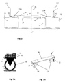
- la figure 2 représente une vue en coupe transversale par rapport au plan médian P1 de la figure 1 illustrant la coopération de la baie avec la palette selon l'invention,
- la figure 3A représente une vue de côté d'un dispositif amovible à roulettes associé à la baie informatique et la figure 3B montre une vue en perspective de ce même dispositif amovible à roulettes,
- la figure 4 montre une vue en perspective d'une baie de l'art antérieur palettisée avec ses rampes de dépalettisation,
- la figure 5 représente un agencement selon l'invention disposé à gauche de la figure et comparé à un agencement connu disposé à droite de la figure,
- la figure 6 montre une vue en perspective d'une baie selon l'invention liée physiquement à la palette à modules séparables de l'invention,
- la figure 7 représente un détail du dessous de la baie selon l'invention,
- la figure 8 illustre la succession d'étapes réalisées selon l'invention lors d'une phase de dépalettisation de la baie informatique.
- FIG. 1 represents a perspective view illustrating the sliding of a pallet according to the invention under a computer rack provided with anchoring means,
- FIG. 2 represents a cross-sectional view with respect to the median plane P1 of FIG. 1 illustrating the cooperation of the bay with the pallet according to the invention,
- FIG. 3A shows a side view of a removable device with wheels associated with the computer rack and FIG. 3B shows a perspective view of this same removable device with wheels,
- FIG. 4 shows a perspective view of a bay of the prior art palletized with its depalletization ramps,
- FIG. 5 represents an arrangement according to the invention disposed on the left of the figure and compared to a known arrangement arranged on the right of the figure,
- FIG. 6 shows a perspective view of a bay according to the invention physically connected to the separable module pallet of the invention,
- FIG. 7 represents a detail of the underside of the bay according to the invention,
- FIG. 8 illustrates the succession of steps performed according to the invention during a depalletization phase of the computer array.
Dans tout ce qui suit, on entendra par baie informatique toute structure de type haute densité avec un matériel permettant une utilisation dans des centres de données, des salles réseau ou des armoires de câblage.In what follows, the term "computer rack" any structure of the high density type with hardware for use in data centers, network rooms or wiring cabinets.
Afin de « maximiser » la hauteur utile d'une baie dont la hauteur hors tout sur palette et emballée ne doit pas dépasser 2 m, l'agencement de conditionnement selon l'invention doit permettre une étroite coopération physique entre le dessus de la palette et la face inférieure de la baie informatique. En effet, la baie dont la masse peut atteindre 1,2 tonnes doit pouvoir être déplacée avec un appareil de levage (50) de type transpalette et passer sous une porte dont la hauteur standard est de 2 m.In order to "maximize" the usable height of a rack with a palletized and packaged overall height of not more than 2 m, the packaging arrangement according to the invention must allow close physical cooperation between the top of the pallet and the underside of the computer bay. Indeed, the bay whose mass can reach 1.2 tons must be able to be moved with a lifting device (50) type pallet and go under a door whose standard height is 2 m.
Dans le mode de réalisation présenté aux figures 1 et 2, la baie informatique est amenée sans ses roulettes sur une palette (2) de transport formée de plusieurs morceaux. Ceci est réalisé préalablement à la livraison de la baie, au cours d'une phase de conditionnement. La baie (1) peut être palettisée ainsi, sans que les roulettes (31) soient initialement fixées sou la baie informatique (1), à condition qu'il soit possible de fixer facilement par la suite les roulettes (31) associées à cette baie (1).In the embodiment shown in Figures 1 and 2, the computer rack is brought without its wheels on a pallet (2) of transport formed of several pieces. This is done prior to delivery of the bay, during a conditioning phase. The bay (1) can be palletized thus, without the wheels (31) are initially fixed sou the computer rack (1), provided that it is possible to easily fix thereafter the wheels (31) associated with this bay (1).
Il est donc important de rendre facile la phase consistant à désolidariser la baie de sa palette et fixer les roulettes. Pour cela, il convient d'utiliser un chariot élévateur (outil commun fortement utilisé, du type transpalette) pour soulever la baie (1) et enlever la palette (2). Nous remarquons qu'à ce moment précis, il est difficile de soulever à la fois la baie (1) en passant un chariot élévateur au travers de la palette (2) et d'enlever cette dernière. Pour résoudre cela, le procédé de conditionnement selon l'invention prévoit l'utilisation dune palette (2) originale en au moins trois morceaux séparables. Tous les morceaux sont liés entre eux par un système mécanique démontable puis désolidarisés pour rendre indépendant le soulèvement de la baie (1) et le retrait de la palette (2).It is therefore important to make easy the phase of separating the bay from its pallet and fix the wheels. For this, it is advisable to use a forklift (common tool used, of the pallet truck type) to raise the bay (1) and remove the pallet (2). We note that at this precise moment, it is difficult to lift both the bay (1) by passing a forklift through the pallet (2) and remove the latter. To solve this, the packaging method according to the invention provides for the use of an original pallet (2) in at least three separable pieces. All the pieces are interconnected by a removable mechanical system and then disengaged to make independent the raising of the bay (1) and the removal of the pallet (2).
En référence à la figure 1, la palette comprend par exemple deux modules latéraux (21, 22) et au moins un moyen support intermédiaire (20) du type séparable du reste de la palette et permettant de raccorder les modules latéraux (21, 22). Les modules latéraux (21, 22) sont séparés l'un de l'autre par le moyen support intermédiaire (20) et répartis de part et d'autre d'un plan médian vertical (P1). Dans un mode de réalisation préféré de l'invention, le moyen support intermédiaire possède une surface correspondant à plus du tiers de la surface de la palette (2), les modules latéraux formant par exemple chacun moins d'un tiers de la surface de la palette (2).With reference to FIG. 1, the pallet comprises, for example, two lateral modules (21, 22) and at least one intermediate support means (20) of the separable type from the remainder of the pallet and making it possible to connect the lateral modules (21, 22). . The lateral modules (21, 22) are separated from each other by the intermediate support means (20) and distributed on either side of a vertical median plane (P1). In a preferred embodiment of the invention, the intermediate support means has a surface corresponding to more than one third of the surface of the pallet (2), the lateral modules forming for example each less than a third of the surface of the pallet (2). pallet (2).
La coopération étroite entre la baie informatique (1) et la palette (2) correspond à un agencement de conditionnement, permettant le transport de la baie (1) à l'aide du chariot élévateur ou tout appareil de levage (50) de ce type. Comme illustré à la figure 2, la baie informatique (1) peut être de forme classique, parallélépipédique, et associée à des roulettes (31) s'étendant verticalement d'une première distance déterminée (H1) par rapport à au moins une face inférieure (10) de cette baie (1). La baie informatique (1) est rendue solidaire de la palette de transport (2) par deux moyens d'ancrage (12) répartis sous la face inférieure (10) de la baie informatique, de part et d'autre du plan médian vertical (P1). Les modules latéraux (21, 22) de la palette (12) comportent chacun des moyens (210, 220, 23) agencés pour se fixer de façon amovible aux moyens d'ancrage (12) respectifs de la baie informatique (1). Ces moyens (210, 220, 23) de fixation et les moyens d'ancrage (12) sont disposés en vis-à-vis de façon à assurer une coopération étroite entre palette (2) et baie (1) et à maintenir en position horizontale la face inférieure (10) de la baie informatique (1).The close cooperation between the computer rack (1) and the pallet (2) corresponds to a packaging arrangement, allowing the transport of the rack (1) by means of the lift truck or any lifting device (50) of this type . As illustrated in Figure 2, the computer rack (1) can be of form conventional, parallelepiped, and associated with rollers (31) extending vertically from a first predetermined distance (H1) relative to at least one lower face (10) of this bay (1). The computer rack (1) is secured to the transport pallet (2) by two anchoring means (12) distributed under the lower face (10) of the computer bay, on either side of the vertical median plane ( P1). The side modules (21, 22) of the pallet (12) each comprise means (210, 220, 23) arranged to be removably attached to the respective anchoring means (12) of the computer rack (1). These fastening means (210, 220, 23) and the anchoring means (12) are arranged vis-à-vis so as to ensure close cooperation between the pallet (2) and the bay (1) and to maintain in position horizontal the lower face (10) of the computer rack (1).
Comme illustré à la figure 2, le dessus de la palette (2) est alors espacé de la face inférieure (10) de la baie informatique (1) d'une seconde distance déterminée (H2) qui est strictement inférieure à la dite première distance déterminée (H1). Autrement dit, le fait de palettiser ainsi la baie informatique sans utiliser les roulettes (31) entre la palette de transport (2) et la baie (1), permet de gagner en hauteur utile, le supplément de hauteur lié aux roulettes étant supprimé. On comprend alors que l'invention apport un gain de hauteur (H3) qui peut être transféré à la baie proprement dite, comme illustré par la figure 5.As illustrated in FIG. 2, the top of the pallet (2) is then spaced from the lower face (10) of the computing rack (1) by a second determined distance (H2) which is strictly less than the said first distance. determined (H1). In other words, thus palletizing the computer bay without using the rollers (31) between the transport pallet (2) and the bay (1), allows to gain useful height, the additional height linked to the wheels being removed. It is understood that the invention provides a height gain (H3) that can be transferred to the bay itself, as shown in Figure 5.
Contrairement aux procédés connus, correspondant à la figure 4, dans lesquels la baie informatique (1) doit être amenée via ses roulettes sur le plateau supérieur de la palette (6) par une rampe de chargement (60) solidaire ou rapportée à la palette (6), la solution selon l'invention propose plutôt de superposer la baie à la palette par déplacement de la palette, suivant la direction des flèches illustrées à la figure 1. L'étape de palettisation comporte en effet une translation horizontale pour disposer ladite palette sous la baie informatique. Cette translation peut s'effectuer en outre parallèlement au plan médian (P1). L'étape de palettisation s'accompagne d'une étape de fixation réalisée lors de la translation horizontale, un premier (21) des modules latéraux de la palette (2) se fixant à un premier des moyens d'ancrage (12) et un second (22) des modules latéraux de la palette se fixant à un second des moyens d'ancrage (12).Unlike known methods, corresponding to FIG. 4, in which the computer rack (1) must be brought via its rollers onto the upper plate of the pallet (6) by a loading ramp (60) secured to or attached to the pallet ( 6), the solution according to the invention rather proposes to superimpose the bay to the pallet by moving the pallet, in the direction of the arrows illustrated in Figure 1. The palletizing step comprises indeed a horizontal translation to arrange said pallet under the computer bay. This translation can also be performed parallel to the median plane (P1). The palletizing step is accompanied by a fixing step performed during the horizontal translation, a first (21) of the lateral modules of the pallet (2) attaching to a first of the anchoring means (12) and a second (22) of the lateral modules of the pallet being fixed to a second anchoring means (12).
Dans le mode de réalisation des figures 2 et 7, les deux moyens d'ancrage (12) comprenant des glissières respectives parallèles adaptées à la fois pour recevoir de façon interchangeable des dispositifs amovibles (3) à roulettes (31) et les moyens (210, 220, 23) de fixation amovible de la palette de transport (2). Ces glissières, disposées de façon sensiblement horizontale, permettent de minimiser l'espacement sous la baie informatique (1) puisque les dispositifs amovibles (3) à roulettes (31) peuvent être séparés de la baie (1). Les roulettes peuvent en variante être rapportées à la baie (1) par un mode de fixation équivalent, par exemple à l'aide de vis, rivet, clips ou autre moyen de fixation amovible. Dans d'autres modes de réalisation de l'invention, les roulettes (31) peuvent être de type escamotable ou pouvant être ramenées dans un logement de la baie (1), respectivement dans un logement de la palette (2). Ces modes de réalisation permettent chacun de réduire l'espacement entre baie et palette à une distance (H2) nettement inférieure au diamètre des roulettes (31) habituellement utilisées pour supporter la baie (pouvant atteindre 1,2 tonnes). Alors que ces roulettes possèdent un diamètre supérieur à 8 cm et que la distance (H1, figure 3A) correspondant à l'encombrement en hauteur de ses roulettes est de l'ordre de 17 cm, la distance (H2) entre baie et palette est par exemple comprise entre 0,4 et 4 cm selon la présente invention.In the embodiment of Figures 2 and 7, the two anchoring means (12) comprising respective parallel slides adapted both to receive interchangeably removable devices (3) with wheels (31) and means (210). , 220, 23) for releasably securing the transport pallet (2). These slides, arranged substantially horizontally, minimize the spacing under the computer rack (1) since the removable devices (3) with wheels (31) can be separated from the bay (1). The casters may alternatively be attached to the bay (1) by an equivalent method of attachment, for example using screws, rivets, clips or other removable fastening means. In other embodiments of the invention, the rollers (31) can be retractable type or can be brought into a housing of the bay (1), respectively in a housing of the pallet (2). These embodiments each make it possible to reduce the spacing between the bay and the pallet at a distance (H2) which is much smaller than the diameter of the rollers (31) usually used to support the bay (up to 1.2 tonnes). While these wheels have a diameter greater than 8 cm and that the distance (H1, Figure 3A) corresponding to the overall height of its wheels is of the order of 17 cm, the distance (H2) between bay and pallet is for example between 0.4 and 4 cm according to the present invention.
Comme montré sur les figures 3A, 3B et 7, chaque dispositif amovible (3) à roulettes (31) est doté d'un organe de coopération (30) prévu pour se fixer à un des moyens d'ancrage (12) de la baie informatique (1). En référence à la figure 2, la baie possède sur sa structure basse ou face inférieure (10) deux jeux de rails de guidages (11) identiques. Ces rails (11) horizontaux, forment les glissières permettant de recevoir par translation tout élément qui dispose d'un système prévu à cet effet : plateau avec roulettes (31) et vérins (32) ou palette avec plateau (par exemple en acier). Dans un mode de réalisation de l'invention, les glissières sont constituées de deux jeux de rails de guidage (11) horizontaux reliés à la face inférieure (10) de la baie informatique (1), le premier jeu de rails étant disposé à une extrémité avant (101) de la baie informatique (1) et le second jeu de rails étant disposé à une extrémité arrière (102) de cette baie (1). Les glissières comprennent chacune au moins un logement délimité par les rails (11) et la face inférieure (10) de la baie informatique (1) pour recevoir en translation le moyen correspondant de fixation prévu sur le dispositif amovible (3) à roulettes ou sur le module latéral (21, 22) de la palette (2).As shown in FIGS. 3A, 3B and 7, each removable device (3) with wheels (31) is provided with a cooperation member (30) intended to be fixed to one of the anchoring means (12) of the rack computer science (1). With reference to FIG. 2, the rack has on its lower structure or lower face (10) two sets of identical guide rails (11). These rails (11) horizontal, form the slideways to receive by translation any element that has a system provided for this purpose: tray with wheels (31) and cylinders (32) or pallet with tray (for example steel). In one embodiment of the invention, the slides consist of two sets of horizontal guide rails (11) connected to the lower face (10) of the computer bay (1), the first set of rails being disposed at a front end (101) of the computer rack (1) and the second set of rails being disposed at a rear end (102) of this bay (1). The slides each comprise at least one housing delimited by the rails (11) and the underside (10) of the computer rack (1) for receiving in translation the corresponding fixing means provided on the removable device (3) with wheels or on the lateral module (21, 22) of the pallet (2).
Le ou les plateaux formant l'organe de coopération (30) peuvent être tout d'abord glissés dans les rails (11) de guidage jusqu'à ce qu'ils soient en position. Dans le mode de réalisation de la figure 7, la position peut être définie par la présence d'une butée mécanique de fin de course. L'organe de butée (35) peut être prévu sur la structure basse de la baie informatique (1), associé à chacune des glissières pour marquer une fin de course du moyen de fixation reçu dans la glissière.The plate or trays forming the cooperation member (30) can be first slid into the guide rails (11) until they are in position. In the embodiment of FIG. 7, the position can be defined by the presence of a mechanical limit stop. The stop member (35) can be provided on the low structure of the computer rack (1), associated with each of the slides to mark a limit of the fastening means received in the slide.
En référence à la figure 6, la palette (2) peut ensuite être liée de façon complémentaire à la baie (1), par exemple à l'aide d'un système démontable de liaison mécanique. Après le positionnement jusqu'à l'organe de butée (35) des moyens de fixation des modules latéraux (21, 22), cette liaison mécanique permet de supprimer le dernier degré de liberté entre la baie (1) et la palette (2). Plus généralement, la palette (2) peut comporter des moyens (40) de blocage en position de la baie (1) répartis sur chacun des modules latéraux (21, 22). La liaison mécanique baie / palette est par exemple assurée par un système de cornière vissée, ce système pouvant être prévu à l'arrière comme à l'avant de la baie informatique (1).With reference to FIG. 6, the pallet (2) can then be linked in a complementary manner to the bay (1), for example by means of a dismountable mechanical linkage system. After positioning the means for fastening the lateral modules (21, 22) to the stop member (35), this mechanical connection makes it possible to eliminate the last degree of freedom between the bay (1) and the pallet (2) . More generally, the pallet (2) may comprise means (40) for blocking the position of the bay (1) distributed on each of the lateral modules (21, 22). The mechanical connection bay / pallet is for example provided by a screwed angle system, this system can be provided at the rear and at the front of the computer bay (1).
Dans le mode de réalisation des figures 1 et 2, la palette (2) comporte un dessus sensiblement horizontal et les modules latéraux (21, 22) peuvent s'apparenter chacun à une portion de palette standard (plancher supérieur, plot, semelle...) à un détail près : chacun des modules latéraux (21, 22) possède au moins un plateau (210, 220) en acier fixé sur le plancher supérieur. C'est ce plateau en acier qui effectue la translation dans les rails (11) de la baie (1) constituant ainsi une liaison glissière entre cette dernière et la palette (2). Le fait d'associer le plateau (210, 220) à la palette (2) assure une certaine rapidité et sécurité lors de la dépalettisation. En outre, les dispositifs amovibles (3) à roulettes peuvent être dotés d'un organe de coopération (30) avec le même type de plateau que les modules latéraux. Ainsi, avec un plateau constitué par exemple d'une plaque en acier, l'installation des dispositifs (3) à roulettes est très rapide, chaque dispositif (3) étant ramené à la baie par glissement du plateau dans les rails de guidage (11). Naturellement, tout autre organe de glissement en translation peut être prévu sur les modules latéraux (21, 22) pour coopérer mécaniquement avec un moyen correspondant monté sous la baie informatique (1), de façon à rendre la baie informatique solidaire de la palette (2).In the embodiment of FIGS. 1 and 2, the pallet (2) has a substantially horizontal top and the lateral modules (21, 22) can each be a part of a standard pallet portion (upper floor, stud, sole. .) to one detail: each of the side modules (21, 22) has at least one plate (210, 220) of steel fixed on the upper floor. It is this steel plate that translates in the rails (11) of the bay (1) thus forming a slide connection between the latter and the pallet (2). Associating the plate (210, 220) with the pallet (2) ensures a certain speed and security when depalletizing. In addition, the removable devices (3) with wheels can be provided with a cooperation member (30) with the same type of plate as the side modules. Thus, with a plate consisting for example of a steel plate, the installation of the devices (3) with wheels is very fast, each device (3) being brought back to the bay by sliding the plate in the guide rails (11). ). Naturally, any other sliding member in translation can be provided on the lateral modules (21, 22) to cooperate mechanically with a corresponding means mounted under the computer rack (1), so as to make the computer bay integral with the pallet (2). ).
Comme illustré à la figure 2, les deux modules latéraux (21, 22) comprennent chacun une surface supérieure équipée d'au moins un plateau (210, 220) surélevé et parallèle à ladite surface supérieure, plateau sous lequel sont formées des gorges ou rainures (23) adjacentes à ladite surface supérieure pour recevoir l'extrémité d'un rail (11) des glissières.As illustrated in FIG. 2, the two lateral modules (21, 22) each comprise an upper surface equipped with at least one plate (210, 220) raised and parallel to said upper surface, a plate under which grooves or grooves are formed. (23) adjacent said upper surface for receiving the end of a rail (11) slides.
Sur le dessus de la palette formé par les faces supérieures respectives des morceaux de la palette (2), on retrouve en plus des plateaux (210, 220) au moins un tasseau (200) formé sur la face supérieure du moyen support intermédiaire (20). La présence de tasseaux (200) assure un soutien de la face inférieure (10) de la baie informatique (1). Le plancher de raccordement formé par le moyen support intermédiaire (20) peut consister en une planche et deux tasseaux (200). Ce plancher de raccordement ou support intermédiaire analogue est ensuite lié mécaniquement par un système démontable aux deux modules latéraux (21, 22). Comme représenté à la figure 1, il faut bien comprendre que la structure de la baie (1) est posée directement sur les embases métalliques (plateaux) et les tasseaux (200) de la palette (2). Comme montré à la figure 2, les plateaux (210, 220) des modules latéraux (21, 22) sont en contact direct avec la face inférieure (10) de la baie informatique (1). Il n'y a plus les roulettes (31) entre le dessus de la palette (2) et le dessous de la baie (1), ce qui permet de gagner en hauteur utile. La disposition proposée selon l'invention permet donc de transporter une baie ayant une hauteur (H) de l'ordre de 1,80 m (40U) sur sa palette (2) jusque dans la salle ou elle sera déballée et mise en fonctionnement.On the top of the pallet formed by the respective upper faces of the pieces of the pallet (2), there are in addition trays (210, 220) at least one cleat (200) formed on the upper face of the intermediate support means (20). ). The presence of cleats (200) provides support for the underside (10) of the computer rack (1). The connecting floor formed by the intermediate support means (20) may consist of a board and two cleats (200). This connecting floor or similar intermediate support is then mechanically linked by a removable system to the two lateral modules (21, 22). As shown in Figure 1, it should be understood that the structure of the bay (1) is placed directly on the metal bases (trays) and cleats (200) of the pallet (2). As shown in Figure 2, the plates (210, 220) of the side modules (21, 22) are in direct contact with the underside (10) of the computer rack (1). There is no longer the rollers (31) between the top of the pallet (2) and the underside of the bay (1), which allows to gain useful height. The proposed arrangement according to the invention allows therefore to carry a bay having a height (H) of the order of 1.80 m (40U) on its pallet (2) to the room where it will be unpacked and put into operation.
Le procédé de conditionnement selon l'invention va être à présent décrit en référence aux figures 1, 2 et 8.The packaging process according to the invention will now be described with reference to FIGS. 1, 2 and 8.
Le procédé comprend au préalable une étape de palettisation pour disposer l'intégralité de la palette (2) sous la baie informatique (1), au cours de laquelle on réalise une étape de fixation entre les modules latéraux de la palette (2) et les moyens d'ancrage (12) de la baie informatique (1). Une fixation complémentaire peut être réalisée, comme montré à la figure 6, pour stabiliser la baie (1) sur la palette (2). Un obstacle qui apparaît après la palettisation est qu'il devient difficile de soutenir la baie palettisée avec un moyen de levage habituel et remplacer la palette (2) par les roulettes (31).The method comprises a prior palletizing step to arrange the entire pallet (2) under the computer rack (1), during which a fixing step is performed between the side modules of the pallet (2) and the pallets (2). anchoring means (12) of the computer rack (1). A complementary attachment can be made, as shown in Figure 6, to stabilize the bay (1) on the pallet (2). An obstacle that appears after palletizing is that it becomes difficult to support the pallet bay with a usual lifting means and replace the pallet (2) by the wheels (31).
Afin de surmonter cet obstacle, le procédé prévoit d'utiliser la palette constituée de morceaux séparables. Le moyen support intermédiaire (20) peut être de moindre épaisseur (e1) par rapport à l'épaisseur (e2) des modules latéraux (21, 22), comme illustré à la figure 2, de façon à laisser un espacement (E) entre le niveau le plus bas de la palette (2) et la partie la plus basse du moyen support intermédiaire (20). Cet espacement (E) permet de faciliter la séparation du moyen support intermédiaire (20) par rapport au reste de la palette (2). En référence à la figure 8, le procédé comporte ainsi une étape (51) d'enlèvement du moyen support intermédiaire (20), au cours de laquelle les modules latéraux (210, 22) respectifs sont désolidarisés de ce moyen support intermédiaire (20). Un déplacement en translation sensiblement horizontale du moyen support intermédiaire (20) est ensuite effectué, de façon à laisser un vide entre les modules latéraux (21, 22). Ceci permet alors d'introduire un transpalette entre les deux modules latéraux (21, 22) pour rendre indépendant le soulèvement de la baie (1) et le retrait du reste de la palette. Ce type de procédure qui utilise un chariot élévateur (transpalette) ou moyen de levage analogue permet de limiter le nombre d'opérateurs à une seule personne.In order to overcome this obstacle, the method provides for using the pallet made of separable pieces. The intermediate support means (20) may be of lesser thickness (e1) with respect to the thickness (e2) of the lateral modules (21, 22), as illustrated in FIG. 2, so as to leave a spacing (E) between the lowest level of the pallet (2) and the lowest part of the intermediate support means (20). This spacing (E) facilitates the separation of the intermediate support means (20) relative to the rest of the pallet (2). With reference to FIG. 8, the method thus comprises a step (51) for removing the intermediate support means (20), during which the respective lateral modules (210, 22) are separated from this intermediate support means (20). . A displacement in substantially horizontal translation of the intermediate support means (20) is then performed, so as to leave a gap between the side modules (21, 22). This then allows to introduce a pallet truck between the two side modules (21, 22) to make independent the lifting of the bay (1) and the removal of the rest of the pallet. This type of procedure that uses a forklift (truck) or similar lifting means limits the number of operators to one person.
Comme représenté à la figure 8, l'étape (51) d'enlèvement du moyen support intermédiaire (20) est donc suivie d'une étape (52) de levage de l'ensemble formé par la baie informatique (1) et le reste (21, 22) de la palette encore fixé à cette baie (1). Lors de cette étape (52), le chariot élévateur est par exemple glissé par le coté entre l'avant de la baie et l'arrière de la baie, les modules latéraux (21, 22) étant disposés transversalement par rapport à la longueur de la baie informatique (1). Ainsi, le centre de gravité de la baie (1) se trouve au-dessus du chariot élévateur : la baie est en équilibre stable. Il s'ensuit une étape (53) d'enlèvement par translation horizontale des modules latéraux (21 22) respectifs pour les remplacer, lors d'une étape suivante (54), par les dispositifs amovibles (3) à roulettes (31). L'insertion de ces dispositifs (3) peut s'effectuer selon un mouvement de translation horizontal. Les roulettes (31) sont ainsi rapportées à la place des deux modules latéraux (21, 22) de la palette (2). La dépalettisation s'achève ainsi, la baie munie de ses roulettes (31) étant reposée sur le sol à l'aide du chariot élévateur.As represented in FIG. 8, the step (51) of removal of the intermediate support means (20) is therefore followed by a step (52) of lifting the assembly formed by the computer rack (1) and the rest (21, 22) of the pallet still attached to this bay (1). During this step (52), the lift truck is for example slid by the side between the front of the bay and the rear of the bay, the lateral modules (21, 22) being arranged transversely with respect to the length of the computer bay (1). Thus, the center of gravity of the bay (1) is above the forklift: the bay is in stable equilibrium. There follows a step (53) of removal by horizontal translation of the respective lateral modules (21 22) to replace them, in a subsequent step (54), by the removable devices (3) with wheels (31). The insertion of these devices (3) can be carried out according to a horizontal translational movement. The rollers (31) are thus reported in place of the two side modules (21, 22) of the pallet (2). The depalletization is thus completed, the bay provided with its wheels (31) being rested on the ground using the forklift.
En référence à la figure 3B, les dispositifs amovibles (3) à roulettes peuvent être dotés chacun d'au moins deux roulettes (31) et d'au moins deux vérins (32) de positionnement au sol ajustables verticalement. Les vérins comportent un socle (34) de contact au sol et un moyen (33) de réglage en hauteur du socle, le réglage en hauteur s'effectuant par exemple par vissage/dévissage.With reference to FIG. 3B, the removable devices (3) with wheels may each be provided with at least two rollers (31) and at least two vertically adjustable positioning cylinders (32) on the ground. The cylinders comprise a base (34) ground contact and means (33) for adjusting the height of the base, the height adjustment being effected for example by screwing / unscrewing.
Un des avantages de l'invention est de fournir un agencement de conditionnement permettant d'augmenter la hauteur utile d'une baie informatique tout en facilitant les opérations de transport sous les portes de hauteur standard (2m), l'agencement étant en outre conçu de façon originale pour faciliter la dépalettisation avec mise au sol de la baie munie de ses roulettes.One of the advantages of the invention is to provide a packaging arrangement for increasing the usable height of a computer bay while facilitating transport operations under standard height doors (2m), the arrangement being furthermore designed in an original way to facilitate the depalletization with putting down of the bay equipped with its wheels.
Il doit être évident pour les personnes versées dans l'art que la présente invention permet des modes de réalisation sous de nombreuses autres formes spécifiques sans l'éloigner du domaine d'application de l'invention comme revendiqué, l'invention ne devant pas être limitée aux détails donnés ci-dessus.It should be obvious to those skilled in the art that the present invention allows embodiments in many other specific forms without departing from the scope of the invention. the invention as claimed, the invention not to be limited to the details given above.
Claims (20)
Applications Claiming Priority (1)
| Application Number | Priority Date | Filing Date | Title |
|---|---|---|---|
| FR0502428A FR2882990B1 (en) | 2005-03-11 | 2005-03-11 | ARRANGEMENT AND METHOD FOR PACKAGING A COMPUTER BAY, COMPUTER BAY AND TRANSPORT PALLET THEREFOR |
Publications (2)
| Publication Number | Publication Date |
|---|---|
| EP1701602A1 true EP1701602A1 (en) | 2006-09-13 |
| EP1701602B1 EP1701602B1 (en) | 2007-12-26 |
Family
ID=35241313
Family Applications (1)
| Application Number | Title | Priority Date | Filing Date |
|---|---|---|---|
| EP06290388A Active EP1701602B1 (en) | 2005-03-11 | 2006-03-09 | System and method for packaging a rack for computer, rack for computer and transport pallet for this rack |
Country Status (4)
| Country | Link |
|---|---|
| US (2) | US20060243690A1 (en) |
| EP (1) | EP1701602B1 (en) |
| DE (1) | DE602006000358T2 (en) |
| FR (1) | FR2882990B1 (en) |
Cited By (4)
| Publication number | Priority date | Publication date | Assignee | Title |
|---|---|---|---|---|
| US20140224698A1 (en) * | 2013-02-08 | 2014-08-14 | The Procter & Gamble Company | Kit for fluffing a cleaning implement |
| CN105621040A (en) * | 2016-02-23 | 2016-06-01 | 广东恒诺通用电气有限公司 | Conveying and storage line for electrical cabinets |
| WO2018002532A1 (en) * | 2016-07-01 | 2018-01-04 | Bull Sas | Floor-loading load-spreading system for computer cabinet |
| US10457443B1 (en) | 2018-11-16 | 2019-10-29 | International Business Machines Corporation | Adjustable pallet |
Families Citing this family (32)
| Publication number | Priority date | Publication date | Assignee | Title |
|---|---|---|---|---|
| FR2882990B1 (en) * | 2005-03-11 | 2007-04-13 | Bull Sa Sa | ARRANGEMENT AND METHOD FOR PACKAGING A COMPUTER BAY, COMPUTER BAY AND TRANSPORT PALLET THEREFOR |
| US20080006593A1 (en) * | 2006-07-05 | 2008-01-10 | Northrop Grumman Corporation | Modular rack design |
| SE530470C2 (en) * | 2006-10-20 | 2008-06-17 | Enjoy Group Ab | Swivel gravity-fed shelf |
| US8671849B2 (en) | 2009-10-23 | 2014-03-18 | Sonoco Development, Inc. | Shipping base with locator pins |
| TW201136818A (en) * | 2010-04-21 | 2011-11-01 | Hon Hai Prec Ind Co Ltd | Server assembly |
| JP5700355B2 (en) * | 2010-09-17 | 2015-04-15 | 株式会社リコー | Pallet equipment |
| TW201218908A (en) * | 2010-10-29 | 2012-05-01 | Hon Hai Prec Ind Co Ltd | Container data center and assembling method thereof |
| US9969414B2 (en) * | 2012-07-31 | 2018-05-15 | Daniel Kelly | Dolly pallet assembly |
| US9282660B2 (en) * | 2013-09-17 | 2016-03-08 | Dell Products, Lp | Modular data center cabinet rack |
| US9532484B2 (en) * | 2013-11-20 | 2016-12-27 | Ara Usa Llc | Rack for mounting and storage of electronic equipment |
| US20150146354A1 (en) * | 2013-11-25 | 2015-05-28 | Silicon Graphics International Corp. | Remote Actuated Leveling Machanism |
| US9686882B2 (en) * | 2014-05-16 | 2017-06-20 | Dell Products, Lp | Modular data center cabinet rack guide and retention mechanism |
| US10836569B2 (en) | 2014-10-06 | 2020-11-17 | Kalitta Air, LLC | System and apparatus for positioning intermodal containers on pallets |
| TWI527741B (en) * | 2014-10-15 | 2016-04-01 | 緯創資通股份有限公司 | Anticollision and shock absorption server packing assembly |
| US10178911B2 (en) | 2015-06-04 | 2019-01-15 | International Business Machines Corporation | Safety apparatus for electrical equipment rack |
| USD857639S1 (en) * | 2016-11-17 | 2019-08-27 | Cooper Technologies Company | Single door for electrical panel enclosure |
| CA2985754A1 (en) | 2016-11-17 | 2018-05-17 | Cooper Technologies Company | One or more doors with one or more angled side flanges for electrical panel enclosure |
| US10172255B2 (en) | 2017-01-26 | 2019-01-01 | International Business Machines Corporation | Enhanced rack/cabinet mobility and stability for a server rack |
| US20180295750A1 (en) * | 2017-04-04 | 2018-10-11 | Scalematrix | Modular rack with adjustable size structures |
| US11419235B2 (en) * | 2017-11-07 | 2022-08-16 | International Business Machines Corporation | Vibration shock mitigation for components in a server rack |
| US11073361B1 (en) * | 2018-05-21 | 2021-07-27 | Advanced American Technologies, LLC | Modular ballistic wall |
| US10618689B1 (en) | 2018-09-28 | 2020-04-14 | International Business Machines Corporation | Top cap guard |
| IL263352B2 (en) * | 2018-11-28 | 2023-07-01 | Moshe Doron | Securing mechanism for casing for transporting communications computers and electronics racks |
| US11167908B2 (en) * | 2018-11-28 | 2021-11-09 | Doron Moshe | Securing mechanism for casing for transporting communications computers and electronics racks |
| US11164146B2 (en) | 2019-11-12 | 2021-11-02 | Dell Products L.P. | Inventory identification |
| US10850757B1 (en) * | 2019-11-12 | 2020-12-01 | Dell Products L.P. | Integrated shock and vibration isolation |
| US11388836B2 (en) * | 2020-01-15 | 2022-07-12 | Dell Products L.P. | Plastic tote |
| US11582874B2 (en) | 2020-01-15 | 2023-02-14 | Dell Products L.P. | Interlocking transportation totes |
| US11622469B2 (en) | 2020-05-04 | 2023-04-04 | Panduit Corp. | Data center cabinet and reusable transport casters for a data center cabinet |
| CN112797443B (en) * | 2020-12-30 | 2023-09-26 | 嵊州市卡梦帝电器有限公司 | Packaging frame for steaming and baking integrated kitchen range and welding method thereof |
| US20220346549A1 (en) * | 2021-04-30 | 2022-11-03 | Advanced Navigation and Positioning Corp. | Rack for transportable aircraft landing system |
| FR3128605A1 (en) | 2021-10-21 | 2023-04-28 | Xavier Dutertre | Arrangement of computer equipment on a pallet |
Citations (5)
| Publication number | Priority date | Publication date | Assignee | Title |
|---|---|---|---|---|
| US5457849A (en) * | 1993-03-29 | 1995-10-17 | Tandem Computers Incorporated | Compact detachable dolly for heavy computer systems |
| EP0897875A1 (en) * | 1997-08-19 | 1999-02-24 | Clip-lok international Limited | An ergonomically designed container for heavy goods |
| FR2816594A3 (en) * | 2000-11-13 | 2002-05-17 | Nord Contenitori S P A | Pallet with high degree of mechanical stiffness for carrying goods of containers, has array of modules positioned side-by-side, forming flat loading surface with slits |
| FR2829467A1 (en) * | 2001-09-11 | 2003-03-14 | Michel Gautier | Transport pallet for heavy objects comprises two assembled parts comprising platform fixed on row of outer feet and central row feet and removable platform fixed on other outer row of feet |
| US6636418B1 (en) * | 2001-08-28 | 2003-10-21 | Emc Corporation | Methods and apparatus for installing electronic cabinets using improved stabilization techniques |
Family Cites Families (34)
| Publication number | Priority date | Publication date | Assignee | Title |
|---|---|---|---|---|
| GB1558141A (en) * | 1977-01-07 | 1979-12-19 | Lansing Bagnall Ltd | Storage racks for warehouses and the like |
| SE420902B (en) * | 1979-07-19 | 1981-11-09 | Claes Nordstrom | PALLET |
| JPH0613079Y2 (en) * | 1987-08-10 | 1994-04-06 | キヤノン株式会社 | Item placement pallet |
| US5137159A (en) * | 1991-02-15 | 1992-08-11 | The Interlake Companies, Inc. | Push-back rack |
| US5230552A (en) * | 1991-06-06 | 1993-07-27 | Steelcase Inc. | Worksurface utilities module |
| EP0601185B1 (en) * | 1991-09-04 | 1997-03-12 | Smc Kabushiki Kaisha | Actuator |
| US5443017A (en) * | 1992-03-27 | 1995-08-22 | Mayline Company, Inc. | Adjustable work table and modular system for the assembly thereof |
| FR2722477B1 (en) * | 1994-07-13 | 1996-08-30 | Bull Sa | TRANSPORT PALLET |
| US6027190A (en) * | 1995-09-07 | 2000-02-22 | Stewart; Edward C. | High density linear motion storage system |
| FR2742126B1 (en) * | 1995-12-08 | 1998-01-02 | Bull Sa | DEPALETTIZATION PROCESS AND RESULTING PALETTE |
| US5802988A (en) * | 1996-11-14 | 1998-09-08 | Steelcase Inc. | Vertically adjustable table |
| NL1008057C2 (en) * | 1998-01-16 | 1999-07-19 | Klaas Schepers | Transport assembly. |
| US6135549A (en) * | 1998-08-14 | 2000-10-24 | Johnson Controls Technology Company | Vehicle seat with computer storage and work table |
| US6126131A (en) * | 1998-10-22 | 2000-10-03 | Tietz; Wayne D. | Pallet for chests and boxes with casters |
| US6943678B2 (en) * | 2000-01-24 | 2005-09-13 | Nextreme, L.L.C. | Thermoformed apparatus having a communications device |
| US7342496B2 (en) * | 2000-01-24 | 2008-03-11 | Nextreme Llc | RF-enabled pallet |
| US6688708B1 (en) * | 2000-02-29 | 2004-02-10 | Spacesaver Corporation | Stabilizing and enclosure system for mobile storage units |
| WO2003068657A2 (en) * | 2000-12-21 | 2003-08-21 | Agile Systems, Inc. | Stowage and retrieval system |
| US6539881B2 (en) * | 2001-02-07 | 2003-04-01 | The Boeing Company | Pallet having a pallet deck with a movable portion and an associated method |
| US6526702B2 (en) * | 2001-02-21 | 2003-03-04 | Wesley C. Jones | Residential program deck |
| US20050149226A1 (en) * | 2002-04-09 | 2005-07-07 | Ebox, Inc. | Warehousing system and method |
| US6955464B1 (en) * | 2001-06-01 | 2005-10-18 | Analogic Corporation | Horizontal drive apparatus and method for patient table |
| US6669314B1 (en) * | 2001-06-08 | 2003-12-30 | Spacesaver Corporation | Modular mobile storage system |
| AU2003249500A1 (en) * | 2002-06-07 | 2003-12-22 | Sankyo Seiki Mfg. Co., Ltd. | Production lines utilizing auto guided pallet and production line design support system |
| US6843180B1 (en) * | 2003-01-30 | 2005-01-18 | Spacesaver Corporation | Anti-tip arrangement for a mobile storage system |
| EP1680758A4 (en) * | 2003-04-07 | 2008-03-26 | Silverbrook Res Pty Ltd | Obtaining product item assistance |
| US7484631B2 (en) * | 2003-11-17 | 2009-02-03 | Nenger Corporation | Modular storage system for logistical management of operational units |
| US7219609B1 (en) * | 2004-01-05 | 2007-05-22 | Diebold Self-Service Systems Division Of Diebold, Incorporated | Apparatus for shipping and installation of ATM |
| US7913629B2 (en) * | 2004-04-29 | 2011-03-29 | Gordon Norman H | Collapsible pallet system and methods |
| US7201243B2 (en) * | 2004-06-22 | 2007-04-10 | Konstant Products, Inc. | Storage carts |
| US7516855B2 (en) * | 2004-06-22 | 2009-04-14 | Konstant Products, Inc. | Storage carts |
| FR2882990B1 (en) * | 2005-03-11 | 2007-04-13 | Bull Sa Sa | ARRANGEMENT AND METHOD FOR PACKAGING A COMPUTER BAY, COMPUTER BAY AND TRANSPORT PALLET THEREFOR |
| US20080295743A1 (en) * | 2007-05-30 | 2008-12-04 | Fcl, Inc. | Table having pivoting communication modules |
| US20090078172A1 (en) * | 2007-09-21 | 2009-03-26 | Kaufmann Jean-Claude | System and method for parking vehicles |
-
2005
- 2005-03-11 FR FR0502428A patent/FR2882990B1/en not_active Expired - Fee Related
-
2006
- 2006-03-03 US US11/366,819 patent/US20060243690A1/en not_active Abandoned
- 2006-03-09 EP EP06290388A patent/EP1701602B1/en active Active
- 2006-03-09 DE DE602006000358T patent/DE602006000358T2/en active Active
-
2008
- 2008-02-05 US US12/068,304 patent/US7699180B2/en active Active
Patent Citations (5)
| Publication number | Priority date | Publication date | Assignee | Title |
|---|---|---|---|---|
| US5457849A (en) * | 1993-03-29 | 1995-10-17 | Tandem Computers Incorporated | Compact detachable dolly for heavy computer systems |
| EP0897875A1 (en) * | 1997-08-19 | 1999-02-24 | Clip-lok international Limited | An ergonomically designed container for heavy goods |
| FR2816594A3 (en) * | 2000-11-13 | 2002-05-17 | Nord Contenitori S P A | Pallet with high degree of mechanical stiffness for carrying goods of containers, has array of modules positioned side-by-side, forming flat loading surface with slits |
| US6636418B1 (en) * | 2001-08-28 | 2003-10-21 | Emc Corporation | Methods and apparatus for installing electronic cabinets using improved stabilization techniques |
| FR2829467A1 (en) * | 2001-09-11 | 2003-03-14 | Michel Gautier | Transport pallet for heavy objects comprises two assembled parts comprising platform fixed on row of outer feet and central row feet and removable platform fixed on other outer row of feet |
Cited By (7)
| Publication number | Priority date | Publication date | Assignee | Title |
|---|---|---|---|---|
| US20140224698A1 (en) * | 2013-02-08 | 2014-08-14 | The Procter & Gamble Company | Kit for fluffing a cleaning implement |
| US9533822B2 (en) * | 2013-02-08 | 2017-01-03 | The Procter & Gamble Company | Kit for fluffing a cleaning implement |
| CN105621040A (en) * | 2016-02-23 | 2016-06-01 | 广东恒诺通用电气有限公司 | Conveying and storage line for electrical cabinets |
| WO2018002532A1 (en) * | 2016-07-01 | 2018-01-04 | Bull Sas | Floor-loading load-spreading system for computer cabinet |
| FR3053486A1 (en) * | 2016-07-01 | 2018-01-05 | Bull Sas | FLOOR LOAD DISTRIBUTION SYSTEM FOR COMPUTER CABINET |
| US10881018B2 (en) | 2016-07-01 | 2020-12-29 | Bull Sas | Floor-loading load-spreading system for computer cabinet |
| US10457443B1 (en) | 2018-11-16 | 2019-10-29 | International Business Machines Corporation | Adjustable pallet |
Also Published As
| Publication number | Publication date |
|---|---|
| EP1701602B1 (en) | 2007-12-26 |
| FR2882990B1 (en) | 2007-04-13 |
| DE602006000358T2 (en) | 2008-12-11 |
| FR2882990A1 (en) | 2006-09-15 |
| US20080156758A1 (en) | 2008-07-03 |
| US7699180B2 (en) | 2010-04-20 |
| US20060243690A1 (en) | 2006-11-02 |
| DE602006000358D1 (en) | 2008-02-07 |
Similar Documents
| Publication | Publication Date | Title |
|---|---|---|
| EP1701602B1 (en) | System and method for packaging a rack for computer, rack for computer and transport pallet for this rack | |
| EP3256409B1 (en) | Method and system for unloading a package | |
| EP3148840B1 (en) | Locking assembly for locking and unlocking a pallet on a support structure | |
| EP2001780A1 (en) | Lifting deck for pallet loader. | |
| WO2012045987A1 (en) | Store for tyre casings | |
| EP3248836B1 (en) | Utility transport vehicle, mobile logistics base comprising such a vehicle, and cell for such a vehicle | |
| EP3647208A1 (en) | Transport truck | |
| EP1427655B1 (en) | Transfer device for linear conveyor | |
| FR2606756A1 (en) | De-caging apparatus, particularly for preserve cans | |
| FR3028280A1 (en) | ROLLING PITCH FOR A TELESCOPIC MAT FOR A PLATE LIFTING APPARATUS, APPARATUS PROVIDED WITH SUCH A PIETEMENT, AND METHOD FOR IMPLEMENTING THE SAME | |
| EP2794131B1 (en) | Device and method for stacking and loading flat objects on edge into a tray comprising multiple compartments, mail-sorting machine, and mail-sorting method | |
| WO2016206967A1 (en) | Truck with tilting tray, for a floor conveyor apparatus | |
| FR2913188A1 (en) | Plates stacking assembly for institutional foodservice, has support descending from top to transferring position, and stacking device with unit that descends support beyond transferring position such that carriage carries plates stack | |
| EP2052994B1 (en) | Storage and retrieval machine with on-board boom lift with conveyor for an automated storage warehouse | |
| FR3097539A1 (en) | Unloading device for boxes of grapes. | |
| EP0929488B1 (en) | Device for palletising stacked quire bundles | |
| WO2023161475A1 (en) | Trailer for transporting a load such as one or more pallets comprising a loading bed with one or more sloping surfaces | |
| EP3880514B1 (en) | Load support intended to be positioned on, locked on and unlocked from a bearing structure by a suitable assembly | |
| EP1186384A1 (en) | Mobile toolbox suitable for aerial working | |
| EP0719717A1 (en) | Kinetic energy controlling device | |
| FR2665149A1 (en) | METHOD FOR PROTECTING A LOAD PLACEMENT PLAN AND DEVICE FOR IMPLEMENTING SAID METHOD. | |
| WO2022008635A1 (en) | Systems for loading and unloading movable stock-picking holders on a mobile autonomous robot for order picking | |
| FR2645129A1 (en) | Improvement to flow-storage installations | |
| FR2717157A1 (en) | Packaging enclosure for windows esp. vehicle windscreens | |
| FR3087760A1 (en) | TRUCK BODY SUPPORT SOLE USED FOR UNLOADING SUCH A TRUCK BUCKET |
Legal Events
| Date | Code | Title | Description |
|---|---|---|---|
| PUAI | Public reference made under article 153(3) epc to a published international application that has entered the european phase |
Free format text: ORIGINAL CODE: 0009012 |
|
| AK | Designated contracting states |
Kind code of ref document: A1 Designated state(s): AT BE BG CH CY CZ DE DK EE ES FI FR GB GR HU IE IS IT LI LT LU LV MC NL PL PT RO SE SI SK TR |
|
| AX | Request for extension of the european patent |
Extension state: AL BA HR MK YU |
|
| 17P | Request for examination filed |
Effective date: 20070307 |
|
| AKX | Designation fees paid |
Designated state(s): DE FR GB IT |
|
| GRAP | Despatch of communication of intention to grant a patent |
Free format text: ORIGINAL CODE: EPIDOSNIGR1 |
|
| RAP1 | Party data changed (applicant data changed or rights of an application transferred) |
Owner name: BULL S.A.S. |
|
| RIN1 | Information on inventor provided before grant (corrected) |
Inventor name: MOLLARD, EMMANUEL Inventor name: COUTANCIER, LIONEL |
|
| GRAS | Grant fee paid |
Free format text: ORIGINAL CODE: EPIDOSNIGR3 |
|
| GRAA | (expected) grant |
Free format text: ORIGINAL CODE: 0009210 |
|
| AK | Designated contracting states |
Kind code of ref document: B1 Designated state(s): DE FR GB IT |
|
| REG | Reference to a national code |
Ref country code: GB Ref legal event code: FG4D Free format text: NOT ENGLISH |
|
| GBT | Gb: translation of ep patent filed (gb section 77(6)(a)/1977) |
Effective date: 20071228 |
|
| REF | Corresponds to: |
Ref document number: 602006000358 Country of ref document: DE Date of ref document: 20080207 Kind code of ref document: P |
|
| PLBE | No opposition filed within time limit |
Free format text: ORIGINAL CODE: 0009261 |
|
| STAA | Information on the status of an ep patent application or granted ep patent |
Free format text: STATUS: NO OPPOSITION FILED WITHIN TIME LIMIT |
|
| 26N | No opposition filed |
Effective date: 20080929 |
|
| REG | Reference to a national code |
Ref country code: FR Ref legal event code: PLFP Year of fee payment: 11 |
|
| REG | Reference to a national code |
Ref country code: FR Ref legal event code: PLFP Year of fee payment: 12 |
|
| REG | Reference to a national code |
Ref country code: FR Ref legal event code: PLFP Year of fee payment: 13 |
|
| PGFP | Annual fee paid to national office [announced via postgrant information from national office to epo] |
Ref country code: IT Payment date: 20200324 Year of fee payment: 15 |
|
| PG25 | Lapsed in a contracting state [announced via postgrant information from national office to epo] |
Ref country code: IT Free format text: LAPSE BECAUSE OF NON-PAYMENT OF DUE FEES Effective date: 20210309 |
|
| PGFP | Annual fee paid to national office [announced via postgrant information from national office to epo] |
Ref country code: FR Payment date: 20230320 Year of fee payment: 18 |
|
| PGFP | Annual fee paid to national office [announced via postgrant information from national office to epo] |
Ref country code: GB Payment date: 20230323 Year of fee payment: 18 Ref country code: DE Payment date: 20230320 Year of fee payment: 18 |
|
| P01 | Opt-out of the competence of the unified patent court (upc) registered |
Effective date: 20230330 |