EP3255737A1 - Connector and connector assembly - Google Patents
Connector and connector assembly Download PDFInfo
- Publication number
- EP3255737A1 EP3255737A1 EP17173133.4A EP17173133A EP3255737A1 EP 3255737 A1 EP3255737 A1 EP 3255737A1 EP 17173133 A EP17173133 A EP 17173133A EP 3255737 A1 EP3255737 A1 EP 3255737A1
- Authority
- EP
- European Patent Office
- Prior art keywords
- connector
- mating
- housing
- state
- cam
- Prior art date
- Legal status (The legal status is an assumption and is not a legal conclusion. Google has not performed a legal analysis and makes no representation as to the accuracy of the status listed.)
- Granted
Links
Images



Classifications
-
- H—ELECTRICITY
- H01—ELECTRIC ELEMENTS
- H01R—ELECTRICALLY-CONDUCTIVE CONNECTIONS; STRUCTURAL ASSOCIATIONS OF A PLURALITY OF MUTUALLY-INSULATED ELECTRICAL CONNECTING ELEMENTS; COUPLING DEVICES; CURRENT COLLECTORS
- H01R13/00—Details of coupling devices of the kinds covered by groups H01R12/70 or H01R24/00 - H01R33/00
- H01R13/62—Means for facilitating engagement or disengagement of coupling parts or for holding them in engagement
- H01R13/629—Additional means for facilitating engagement or disengagement of coupling parts, e.g. aligning or guiding means, levers, gas pressure electrical locking indicators, manufacturing tolerances
- H01R13/62977—Pivoting levers actuating linearly camming means
-
- H—ELECTRICITY
- H01—ELECTRIC ELEMENTS
- H01R—ELECTRICALLY-CONDUCTIVE CONNECTIONS; STRUCTURAL ASSOCIATIONS OF A PLURALITY OF MUTUALLY-INSULATED ELECTRICAL CONNECTING ELEMENTS; COUPLING DEVICES; CURRENT COLLECTORS
- H01R13/00—Details of coupling devices of the kinds covered by groups H01R12/70 or H01R24/00 - H01R33/00
- H01R13/46—Bases; Cases
- H01R13/533—Bases, cases made for use in extreme conditions, e.g. high temperature, radiation, vibration, corrosive environment, pressure
-
- H—ELECTRICITY
- H01—ELECTRIC ELEMENTS
- H01R—ELECTRICALLY-CONDUCTIVE CONNECTIONS; STRUCTURAL ASSOCIATIONS OF A PLURALITY OF MUTUALLY-INSULATED ELECTRICAL CONNECTING ELEMENTS; COUPLING DEVICES; CURRENT COLLECTORS
- H01R13/00—Details of coupling devices of the kinds covered by groups H01R12/70 or H01R24/00 - H01R33/00
- H01R13/02—Contact members
- H01R13/26—Pin or blade contacts for sliding co-operation on one side only
-
- H—ELECTRICITY
- H01—ELECTRIC ELEMENTS
- H01R—ELECTRICALLY-CONDUCTIVE CONNECTIONS; STRUCTURAL ASSOCIATIONS OF A PLURALITY OF MUTUALLY-INSULATED ELECTRICAL CONNECTING ELEMENTS; COUPLING DEVICES; CURRENT COLLECTORS
- H01R13/00—Details of coupling devices of the kinds covered by groups H01R12/70 or H01R24/00 - H01R33/00
- H01R13/62—Means for facilitating engagement or disengagement of coupling parts or for holding them in engagement
- H01R13/627—Snap or like fastening
-
- H—ELECTRICITY
- H01—ELECTRIC ELEMENTS
- H01R—ELECTRICALLY-CONDUCTIVE CONNECTIONS; STRUCTURAL ASSOCIATIONS OF A PLURALITY OF MUTUALLY-INSULATED ELECTRICAL CONNECTING ELEMENTS; COUPLING DEVICES; CURRENT COLLECTORS
- H01R13/00—Details of coupling devices of the kinds covered by groups H01R12/70 or H01R24/00 - H01R33/00
- H01R13/62—Means for facilitating engagement or disengagement of coupling parts or for holding them in engagement
- H01R13/627—Snap or like fastening
- H01R13/6271—Latching means integral with the housing
- H01R13/6272—Latching means integral with the housing comprising a single latching arm
-
- H—ELECTRICITY
- H01—ELECTRIC ELEMENTS
- H01R—ELECTRICALLY-CONDUCTIVE CONNECTIONS; STRUCTURAL ASSOCIATIONS OF A PLURALITY OF MUTUALLY-INSULATED ELECTRICAL CONNECTING ELEMENTS; COUPLING DEVICES; CURRENT COLLECTORS
- H01R13/00—Details of coupling devices of the kinds covered by groups H01R12/70 or H01R24/00 - H01R33/00
- H01R13/62—Means for facilitating engagement or disengagement of coupling parts or for holding them in engagement
- H01R13/627—Snap or like fastening
- H01R13/6275—Latching arms not integral with the housing
-
- H—ELECTRICITY
- H01—ELECTRIC ELEMENTS
- H01R—ELECTRICALLY-CONDUCTIVE CONNECTIONS; STRUCTURAL ASSOCIATIONS OF A PLURALITY OF MUTUALLY-INSULATED ELECTRICAL CONNECTING ELEMENTS; COUPLING DEVICES; CURRENT COLLECTORS
- H01R13/00—Details of coupling devices of the kinds covered by groups H01R12/70 or H01R24/00 - H01R33/00
- H01R13/62—Means for facilitating engagement or disengagement of coupling parts or for holding them in engagement
- H01R13/629—Additional means for facilitating engagement or disengagement of coupling parts, e.g. aligning or guiding means, levers, gas pressure electrical locking indicators, manufacturing tolerances
- H01R13/62905—Additional means for facilitating engagement or disengagement of coupling parts, e.g. aligning or guiding means, levers, gas pressure electrical locking indicators, manufacturing tolerances comprising a camming member
- H01R13/62927—Comprising supplementary or additional locking means
-
- H—ELECTRICITY
- H01—ELECTRIC ELEMENTS
- H01R—ELECTRICALLY-CONDUCTIVE CONNECTIONS; STRUCTURAL ASSOCIATIONS OF A PLURALITY OF MUTUALLY-INSULATED ELECTRICAL CONNECTING ELEMENTS; COUPLING DEVICES; CURRENT COLLECTORS
- H01R13/00—Details of coupling devices of the kinds covered by groups H01R12/70 or H01R24/00 - H01R33/00
- H01R13/62—Means for facilitating engagement or disengagement of coupling parts or for holding them in engagement
- H01R13/629—Additional means for facilitating engagement or disengagement of coupling parts, e.g. aligning or guiding means, levers, gas pressure electrical locking indicators, manufacturing tolerances
- H01R13/62933—Comprising exclusively pivoting lever
- H01R13/62955—Pivoting lever comprising supplementary/additional locking means
-
- H—ELECTRICITY
- H01—ELECTRIC ELEMENTS
- H01R—ELECTRICALLY-CONDUCTIVE CONNECTIONS; STRUCTURAL ASSOCIATIONS OF A PLURALITY OF MUTUALLY-INSULATED ELECTRICAL CONNECTING ELEMENTS; COUPLING DEVICES; CURRENT COLLECTORS
- H01R2201/00—Connectors or connections adapted for particular applications
- H01R2201/26—Connectors or connections adapted for particular applications for vehicles
Definitions
- the present invention relates to a connector and a connector assembly which have configurations to prevent looseness between housings.
- connectors are required to be arranged in such a location to which vibrations are conducted as one near an engine in an engine room of an automobile.
- contact sections of the connectors may be rubbed with each other to be scraped, leading to contact failures. For this reason, a configuration to prevent looseness between the housings is required.
- Japanese Patent Publication JP 2011-23201A a configuration is proposed in which a spring member is arranged between respective housings to prevent looseness between the housings.
- the spring member is provided to prevent looseness between the housings.
- the spring member is sandwiched between the respective housings to press the spring member in a mating direction so as to cause the spring member to be deformed elastically.
- a force required to cause the spring member to be deformed elastically is directly added to a force required for mating when the spring member is not provided, and thus, the mating force may become excessive.
- a locking mechanism strong enough to counter a restoring force of the spring member being deformed elastically is required.
- the present invention has been made in view of the above circumstances to provide a connector and a connector assembly which have configurations to prevent looseness between housings while reducing a mating force compared to the configuration proposed in the above-described Japanese Patent Publication JP 2011-23201A .
- a connector includes: a first housing that includes a mating section to mate with a second housing which is a housing of a second connector; and a spring member that is fixed to the first housing and is inserted into a groove provided in the second housing being mated therewith in a mating direction to be deformed elastically in a direction intersecting the mating direction so as to prevent looseness between the first housing and the second housing.
- the connector according to the first aspect of the present invention has the configuration in which the spring member is provided and the spring member is inserted into the groove of the second housing in the mating direction.
- the spring member inserted into the groove is deformed elastically in the direction intersecting the mating direction to prevent looseness. Accordingly, looseness between the housings is prevented while reducing the mating force.
- the connector further includes: a cam member that receives a cam pin provided in the second housing to be slid in a direction intersecting the mating direction and draw in the cam pin so as to cause the second housing to be mated; and an operation lever that causes the cam member to slide by a rotating operation.
- the mating section has an approximately rectangular shape when being projected in the mating direction, and the spring member is provided on each of a short side and a long side of the approximately rectangular shape of the mating section.
- a connector assembly includes: a first connector including a first housing and a second connector including a second housing which mate with each other, wherein the first connector includes a spring member fixed to the first housing, and the second connector includes a groove which is formed in the second housing, into which the spring member is inserted in a mating direction at the time of mating to be deformed elastically in a direction intersecting the mating direction so as to prevent looseness between the first housing and the second housing via the spring member.
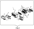
- FIG. 1 is an exploded perspective view of a connector as an embodiment of the present invention.
- first connector 1 a mating connector to mate with the first connector
- second connector 2 a mating connector to mate with the first connector
- a large number of terminals, each of which is connected to one end of an electrical wire, are inserted into the connector 1 illustrated in the exploded perspective view in the FIG. 1 .
- illustrations of the electrical wires and the like are omitted in here.
- the connector 1 illustrated in FIG. 1 includes an operation lever 10.
- the operation lever 10 is provided with pinon gears 11.
- the operation lever 10 is a member to cause cam members 40, which will be described later, to slide by a rotating operation of an operator.
- the first connector 1 includes a wire cover 20.
- This wire cover 20 includes an opening 21 through which the not-illustrated large number of wires, to ends of which the terminals are connected, pass.
- the first connector 1 includes a housing configured with three parts; an outer housing 30; an inner housing 70; and a front housing 100.
- the housing configured with the three parts of the outer housing 30, the inner housing 70 and the front housing 100 corresponds to an example of the first housing according to the present invention.
- the outer housing 30 is provided with two grooves communicating with openings which open in side walls thereof, and the two cam members 40 having plate shapes are inserted into the grooves, respectively.
- These cam members 40 are provided with racks 41.
- the racks 41 engage with the pinion gears 11 of the operation lever 10, and the cam members 40 are slid in a lateral direction indicated with arrows X-X' in FIG. 1 by the rotating operation of the operation lever 10.
- the first connector 1 includes two seal members 50, 90.
- One seal member 50 of them is arranged inside an opening 71 of the inner housing 70.
- the seal member 50 closely contacts a surrounding wall of the opening 71, and also surrounds the not-illustrated electrical wires to closely contact the respective electrical wires, playing a role in forming a sealing structure between them.
- the other seal member 90 surrounds an outer circumference of the inner housing 70, and plays a role in sealing between the inner housing 70 and the second connector 2 (see FIG. 9 , FIG. 11 , FIG. 12 ) being mated therewith.
- the first connector 1 includes a retainer 80.
- This retainer 80 is inserted in a direction of arrows Y into a groove 72 which opens in a lateral direction of the inner housing 70.
- the retainer 80 plays a role in securely positioning and fixing the not-illustrated terminals in the inner housing 70.
- the first connector 1 includes six spring members 60. Tail sections of those spring members 60 are press-fitted into the inner housing 70, and the spring members 60 protrude in a mating direction indicated by arrow Z.
- Two pieces of the six spring members 60 are press-fitted into two short or relatively shorter sides of the approximately rectangular shape, one piece into each short side.
- the remaining four pieces of the six spring members 60 are press-fitted into the two long or relatively longer sides of the approximately rectangular shape, two pieces into each long side.
- the two spring members 60 which are press-fitted into each long side are each press-fitted into a position near a respective short side. Operations of these spring members 60 will be explained later.
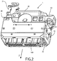
- FIG. 2 is a perspective view illustrating a state in which the first connector illustrated with the exploded perspective view in FIG. 1 is assembled.
- a mating opening 32 which opens in the mating direction (the direction indicated by arrow Z) is formed in the outer housing 30.
- the inner housing 70 (see FIG. 1 ) and the front housing 100 are arranged in the mating opening 32.
- the front housing 100 forms a circumferential space for mating with the second connector between the outer housing 30 and the front housing 100, and protrudes from the mating opening 32.
- the operation lever 10 is rotated to a state of complete mating of the second connector 2.
- the cam members 40 are in a state of completely being inserted into the grooves communicating with the opening 31.
- FIG. 3 is a perspective view illustrating a remaining assembly in which the wire cover, the operation lever and the outer housing are removed from the first connector in the assembled state illustrated in FIG. 2 .
- the inner housing 70, the seal member 90, the front housing 100 and the spring members 60 appear in FIG. 3 .
- the spring members 60 are press-fitted into the inner housing 70, and protrude from the inner housing 70 in the mating direction (the direction of arrow Z).
- Spring members 60 which are press-fitted into left and right short sides (one piece each side) and two spring members 60 which are press-fitted into each of the long sides, each of which is positioned near a respective one of the short sides, are illustrated.
- Two spring members 60 are also similarly press-fitted into the long side opposite to the long side illustrated in FIG. 3 .
- a long groove 74 sandwiched between two rails 73, and extending along the long side is formed in the inner housing 70.
- Two rails 73 and a long groove 74 are also formed similarly in a long side on the opposite side which long side does not appear in FIG. 3 .
- Bosses 42 (see FIG. 4 ) of the cam member 40 enter this long groove 74.
- the cam member 40 is slid in the lateral direction indicated by arrows X-X' while being guided by the long groove 74 in a state in which the bosses 42 enter the long groove 74.
- a narrowed section 741 in which a groove width is narrowed is formed at each of two locations. Operations of the narrowed sections 741 will be described later.
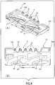
- FIG. 4 illustrates a perspective view (Part A) and a plan view (Part B) of a cam member.
- the two cam members 40 are provided in the first connector 1 as illustrated in FIG. 1 .
- the cam member 40 illustrated in FIG. 4 is one cam member 40 of those two cam members 40.
- the other cam member 40 has a mirror image with respect to the cam member 40 illustrated in FIG. 4 .
- a rack 41 is provided in this cam member 40.
- This rack 41 plays a role in engaging with the pinion gear 11 of the operation lever 10 illustrated in FIG. 1 to cause the cam member 40 to slide in the lateral direction (the direction of arrows X-X') according to the rotating operation of the operation lever 10.
- bosses 42 aligned laterally are provided on this cam member 40. These bosses 42 enter the long groove 74 illustrated in FIG. 3 .
- the cam member 40 is slid while being guided by the long groove 74.
- This cam member 40 plays a role in drawing in the second connector 2 toward complete mating in such a manner as explained in the following.
- the cam member 40 receives a force from the second connector 2 when drawing in the second connector 2.
- a reason why the six bosses 42 are formed on this cam member 40 is for providing strength enough to catch the force to be received from the mating second connector 2.
- cam grooves 43 are formed in this cam member 40.
- Mating protrusions 202 (see FIG. 10 ) provided on a housing 201 (see FIG. 11 , FIG. 12 ) of the second connector 2 to mate with the first connector 1 enter these cam grooves 43.
- Each of the mating protrusions 202 corresponds to the cam pin according to the present invention.
- narrowed sections 431 in each of which a groove width is narrowed are provided in the deepest portions thereof. Operations of the narrowed sections 431 will be described later.
- FIG. 5 illustrates a side view (Part A) and a plan view (Part B) of the first connector.
- the operation lever 10 is in a posture of standing up.
- a state of the first connector 1 when the operation lever 10 is in the posture of standing up is referred to as "a mating starting state.”
- a state of the first connector 1 when the operation lever 10 is in the posture of being lowered illustrated in FIG. 2 is referred to as "a complete mating state.”
- a state of the connector 1 when the operation lever 10 is operated and rotated halfway from the position of standing up as illustrated in FIG. 5 toward the position of being lowered as illustrated in FIG. 2 is referred to as "a halfway mating state.”
- FIG. 6 illustrates sectional views along arrows A-A illustrated in FIG. 5 of the first connector.
- FIG. 5 illustrates the first connector 1 in "the mating starting state.” Accordingly, to be more precise, of the three sectional views in Part (A), Part (B) and Part (C) of FIG. 6 , the sectional view of "the mating starting state"illustrated in Part (A) of FIG. 6 corresponds to the sectional view along arrows A-A illustrated in FIG. 5 .
- Part (B) and Part (C) of FIG. 6 illustrate the sectional views of "the halfway mating state” and "the complete mating state” at the same location as arrows A-A illustrated in FIG. 5 , respectively. This similarly applies to FIG. 7 , FIG. 10 and so on which will be described later.
- the cam member 40 When the cam member 40 is in "the mating starting state" illustrated in FIG. 6 , the cam member 40 is at a position to receive the mating protrusions 202 of the second connector 2. The cam member 40 draws in the mating protrusions 202 in the direction of arrow Z' as the state proceeds to "the halfway mating state” and further to "the complete mating state".
- FIG. 7 illustrates sectional views along arrows B-B illustrated in FIG. 5 of the first connector.
- Part (A), Part (B) and Part (C) of FIG. 6 similarly to Part (A), Part (B) and Part (C) of FIG. 7 illustrate "the mating starting state", "the halfway mating state” and "the complete mating state", respectively.
- the six bosses 42 provided on the cam member 40 are illustrated in this FIG. 7 . These six bosses 42 move in the direction of arrow X' as the state proceeds from “the mating starting state” to “the halfway mating state” and further to “the complete mating state.” In “the complete mating state” illustrated in Part (C) of FIG. 7 , two bosses 42a of both ends of those six bosses 42 reach a state of being caught by the narrowed sections 741 of the long groove 74 provided in the inner housing 70.
- FIG. 8 illustrates schematic diagrams illustrating states in which the boss of the cam member is caught by the narrowed section.
- a state in which the boss 42a is at a position immediately before being caught by the narrowed section 741 is illustrated in Part (A) of FIG. 8 .
- Part (B) of FIG. 8 a state in which the boss 42a iscaught by the narrowed section 741 is illustrated in Part (B) of FIG. 8 .
- the cam member 40 is slid in the direction of arrow X' up to "the complete mating state.” Then, as illustrated in Part (B) of FIG. 8 , the two bosses 42a of the both ends of the six bosses 42 provided on the cam member 40 reach the state of being caught by the narrowed sections 741 of the long groove 74 provided in the inner housing 70. Groove widths of the narrowed sections 741 are made to be ones into which the bosses 42s are lightly press-fitted. When the bosses 42a are press-fitted into the narrowed sections 741, the cam members 40 are united with the housing (the inner housing 70), and a state in which looseness between them is prevented is obtained.
- FIG. 9 illustrates side views of a connector assembly including the first connector and the second connector (Part A) and a sectional view along arrows C-C illustrated in Part A of FIG. 9 (Part B).
- the first connector 1 is in "the mating starting state" as same as being in FIG. 5
- the first connector 1 and the second connector 2 are in a temporary mating state.
- FIG. 10 illustrates sectional views along arrows D-D illustrated in FIG. 9 .
- Part (A), Part (B) and Part (C) of FIG. 10 illustrate sectional views of "the mating starting state", "the halfway mating state” and "the complete mating state", respectively.
- the mating protrusions 202 provided on the housing 201 (see FIG. 11 , FIG. 12 ) of the second connector 2 are illustrated in this FIG. 10 .
- the second connector 2 When the first connector 1 is in "the mating starting state" illustrated in the Part (A) of FIG. 10 , the second connector 2 is inserted to the first connector 1 up to a temporary mating state. Then, as illustrated in Part (A) of FIG. 10 , the mating protrusions 202 of the second connector 2 enter entrance sections of the cam grooves 43 of the cam member 40. Subsequently, the operation lever starts being lowered, and the state is proceeding to "the halfway mating state" (Part (B) of FIG. 10 ), and further to "the complete mating state” (Part (C) of FIG. 10 ).
- the cam grooves 43 include the narrowed sections 431 in which the widths of the grooves 43 are narrowed at the locations where the mating protrusions 202 are positioned in "the complete mating state.”
- the groove widths in the narrowed sections 431 are wide to the extent that the mating protrusions 202 are lightly press-fitted into the narrowed sections 431. Accordingly, in “the complete mating state” illustrated in Part (C) of FIG. 10 , the housing 201 of the second connector 2 is united with this cam member 40, and the state in which looseness between them is prevented is obtained. In “the complete mating state", as explained with reference to FIG. 7 and FIG.
- the bosses 42a of the both ends of the cam member 40 are caught by the narrowed sections 741 of the long groove 74 of the housing (the inner housing 70) of the first connector 1.
- the first connector 1 and the second connector 2 are united with each other via the cam members 40, and thus looseness between them is prevented.
- the looseness prevention configuration via the cam members 40 is specifically effective for looseness prevention in the mating direction (the direction of arrow Z' or the direction of arrow Z illustrated in FIG. 1 ).
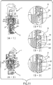
- FIG. 11 illustrates sectional views along arrows E-E illustrated in FIG. 9 (Part A-1, Part A-3) and partially enlarged views (Part B-1, Part B-2, Part B-3).
- Part (A-1) and Part (A-3) of the FIG. 11 illustrate sectional views of "the mating starting state” and "the complete mating state", respectively.
- illustrations of a sectional view in "the halfway mating state” are omitted in here.
- Part (B-1) and Part (B-3) of FIG. 11 are enlarged views of portions indicated by circles R illustrated in Part (A-1) and Part (A-3) of FIG. 11 , respectively.
- Part (B-2) of FIG. 11 is an enlarged view of a corresponding portion in "the halfway mating state.”
- Spring members 60 are illustrated in this FIG. 11 .
- the spring members 60 illustrated in this FIG. 11 are the spring members 60 arranged on the long sides of the mating section which forms the approximately rectangular shape when being projected in the mating direction. These spring members 60 are firmly press-fitted into the inner housing 70. And those spring members 60 are exposed from the inner housing 70, and protrude toward the second connector 2.
- grooves 203 which allow the spring members 60 to enter the grooves 203 are provided in the housing 201 of the second connector 2. These spring members 60 are inserted into the grooves 203 of the housing 201 in the second connector 2 being mated therewithin the mating direction.
- the spring members 60 are inserted into the grooves 203, the spring members 60 are elastically deformed in a direction intersecting the mating direction (a horizontal direction of FIG. 11 ).
- the spring members 60 are illustrated while maintaining a state before being elastically deformed. For this reason, the spring member 60 is illustrated in a state in which the spring member 60 bites into a wall surface of the groove 203.
- the spring member 60 is press-fitted by the wall surface of the groove 203 to be elastically deformed.
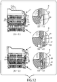
- FIG. 12 illustrates sectional views along arrows C-C illustrated in FIG. 9 (Part A-1, Part A-3) and partially enlarged views (Part B-1, Part B-2, Part B-3).
- Part (A-1) and Part (A-3) of the FIG. 12 illustrate sectional views of "the mating starting state” and "the complete mating state", respectively. Illustrations of a sectional view in "the halfway mating state” are omitted.
- Part (B-1) and Part (B-3) of FIG. 12 are enlarged views of portions indicated by circles R illustrated in Part (A-1) and Part (A-3) of FIG. 12 , respectively.
- Part (B-2) of FIG. 12 is an enlarged view of a corresponding portion in "the halfway mating state.”
- spring members 60 are illustrated also in this FIG. 12 .
- the spring members 60 illustrated in this FIG. 12 are the spring members 60 arranged on the short sides of the mating section which forms the approximately rectangular shape when being projected in the mating direction. These spring members 60 are firmly press-fitted into the inner housing 70. And those spring members 60 are exposed from the inner housing 70 and protrude toward the second connector 2.
- the grooves 203 which allow the spring members 60 to enter the grooves 203 are provided in the housing 201 of the second connector 2.These spring members 60 are inserted into the grooves 203 of the housing 201 in the second connector 2 being mated therewith in the mating direction.
- the spring members 60 are elastically deformed in a direction intersecting the mating direction (a horizontal direction of the FIG. 12 ).
- the spring members 60 are illustrated while maintaining a state before being elastically deformed.
- the spring member 60 is illustrated in a state in which the spring member 60 bites into the wall surface of the groove 203.
- the spring member 60 is press-fitted by the wall surface of the groove 203 to be elastically deformed.
- These spring members 60 are provided by six pieces totally as illustrated in FIG. 1 . These spring members 60 are press-fitted into the housing (the inner housing 70) of the first connector 1, and the spring members 60 enter the grooves 203 of the housing 201 of the second connector 2 in the state of being elastically deformed at the time of mating. In the present embodiments, by the spring members 60 and the grooves 203, looseness between the first connector 1 and the second connector 2 is prevented.
- the looseness prevention configuration by the spring members 60 and the grooves 203 are effective mainly for preventing looseness in a direction on a plane intersecting the mating direction.
- the six spring members 60 are provided in the present embodiment, and however, the number of the spring members 60 is not limited to six and the spring members 60 may be provided as many as effective enough only for preventing looseness.
- the spring members 60 are provided on each of the long sides and the short sides of the mating section in the present embodiment, and however, in a case in which a direction of vibration is limited, the spring members 60 may be provided, for example, only on the short sides or only on the long sides for preventing looseness in a direction according to the direction of vibration.
- the spring members 60 are arranged behind the seal member 90 along the mating direction Z, and however, the spring members 60 may be arranged at a position ahead of the seal member 90 (a position of F in FIG. 11 ).
Landscapes
- Details Of Connecting Devices For Male And Female Coupling (AREA)
- Connector Housings Or Holding Contact Members (AREA)
Abstract
Description
- The present invention relates to a connector and a connector assembly which have configurations to prevent looseness between housings.
- There is a case in which connectors are required to be arranged in such a location to which vibrations are conducted as one near an engine in an engine room of an automobile. In such case, if looseness occurs between housings, contact sections of the connectors may be rubbed with each other to be scraped, leading to contact failures. For this reason, a configuration to prevent looseness between the housings is required.
- Here, in Japanese Patent Publication
JP 2011-23201A - In the case of the above-described Japanese Patent Publication
JP 2011-23201A JP 2011-23201A - The present invention has been made in view of the above circumstances to provide a connector and a connector assembly which have configurations to prevent looseness between housings while reducing a mating force compared to the configuration proposed in the above-described Japanese Patent Publication
JP 2011-23201A - A connector according a first aspect of the present invention includes: a first housing that includes a mating section to mate with a second housing which is a housing of a second connector; and a spring member that is fixed to the first housing and is inserted into a groove provided in the second housing being mated therewith in a mating direction to be deformed elastically in a direction intersecting the mating direction so as to prevent looseness between the first housing and the second housing.
- The connector according to the first aspect of the present invention has the configuration in which the spring member is provided and the spring member is inserted into the groove of the second housing in the mating direction. The spring member inserted into the groove is deformed elastically in the direction intersecting the mating direction to prevent looseness. Accordingly, looseness between the housings is prevented while reducing the mating force.
- Here, in the connector according to the first aspect of the present invention, it is preferable that the connector further includes: a cam member that receives a cam pin provided in the second housing to be slid in a direction intersecting the mating direction and draw in the cam pin so as to cause the second housing to be mated; and an operation lever that causes the cam member to slide by a rotating operation.
- When such a cam member and such an operation lever are provided, it is possible to reduce a force required for mating of an operator.
- In addition, in the connector according to the first aspect of the present invention, it is preferable that the mating section has an approximately rectangular shape when being projected in the mating direction, and the spring member is provided on each of a short side and a long side of the approximately rectangular shape of the mating section.
- When a looseness preventing configuration including the above-described spring member and the above-described groove is provided in each of the above-described short side and the long side, looseness with respect to vibrations in plural directions is prevented.
- A connector assembly according to a second aspect of the present invention includes: a first connector including a first housing and a second connector including a second housing which mate with each other, wherein the first connector includes a spring member fixed to the first housing, and the second connector includes a groove which is formed in the second housing, into which the spring member is inserted in a mating direction at the time of mating to be deformed elastically in a direction intersecting the mating direction so as to prevent looseness between the first housing and the second housing via the spring member.
- According to the above present invention, it is possible to prevent looseness between the housings while repressing an increase of the mating force.
-
-
FIG. 1 is an exploded perspective view of a connector as an embodiment of the present invention; -
FIG. 2 is a perspective view illustrating a state in which the first connector illustrated in the exploded perspective view inFIG. 1 is assembled; -
FIG. 3 is a perspective view illustrating a remaining assembly in which a wire cover, an operation lever and an outer housing are removed from the first connector in the assembled state illustrated inFIG. 2 ; -
FIG. 4 illustrates a perspective view (Part A) and a plan view (Part B) of the cam member; -
FIG. 5 illustrates a side view (Part A) and a plan view (Part B) of the first connector; -
FIG. 6 illustrates sectional views along arrows A-A illustrated inFIG. 5 of the first connector; -
FIG. 7 illustrates sectional views along arrows B-B illustrated inFIG. 5 of the first connector; -
FIG. 8 illustrates schematic diagrams illustrating states in which a boss of the cam member is caught by a narrowed section; -
FIG. 9 illustrates side views of a connector assembly including the first connector and a second connector (Part A) and a sectional view along arrows C-C illustrated in Part A ofFIG. 9 (Part B); -
FIG. 10 illustrates sectional views along arrows D-D illustrated inFIG. 9 ; -
FIG. 11 illustrates sectional views along arrows E-E illustrated inFIG. 9 (Part A-1, Part A-3) and partially enlarged views (Part B-1, Part B-2, Part B-3); and -
FIG. 12 is sectional views along arrows C-C illustrated inFIG. 9 (Part A-1, Part A-3) and partially enlarged views (Part B-1, Part B-2, Part B-3). - Exemplary embodiments of the present invention will be explained in the following.
-
FIG. 1 is an exploded perspective view of a connector as an embodiment of the present invention. - In here, the connector illustrated by the exploded perspective view in
FIG. 1 is referred to as afirst connector 1, and a mating connector to mate with the first connector is referred to as a second connector 2 (seeFIG. 9 ). A connector assembly as an embodiment is configured with thesefirst connector 1 andsecond connector 2. - A large number of terminals, each of which is connected to one end of an electrical wire, are inserted into the
connector 1 illustrated in the exploded perspective view in theFIG. 1 . However, illustrations of the electrical wires and the like are omitted in here. - In addition, the
connector 1 illustrated inFIG. 1 includes anoperation lever 10. Theoperation lever 10 is provided withpinon gears 11. Theoperation lever 10 is a member to causecam members 40, which will be described later, to slide by a rotating operation of an operator. - In addition, the
first connector 1 includes awire cover 20. Thiswire cover 20 includes anopening 21 through which the not-illustrated large number of wires, to ends of which the terminals are connected, pass. - In addition, the
first connector 1 includes a housing configured with three parts; anouter housing 30; aninner housing 70; and afront housing 100. The housing configured with the three parts of theouter housing 30, theinner housing 70 and thefront housing 100 corresponds to an example of the first housing according to the present invention. - The
outer housing 30 is provided with two grooves communicating with openings which open in side walls thereof, and the twocam members 40 having plate shapes are inserted into the grooves, respectively. Thesecam members 40 are provided withracks 41. Theracks 41 engage with thepinion gears 11 of theoperation lever 10, and thecam members 40 are slid in a lateral direction indicated with arrows X-X' inFIG. 1 by the rotating operation of theoperation lever 10. - In addition, the
first connector 1 includes twoseal members 50, 90. One seal member 50 of them is arranged inside an opening 71 of theinner housing 70. The seal member 50 closely contacts a surrounding wall of the opening 71, and also surrounds the not-illustrated electrical wires to closely contact the respective electrical wires, playing a role in forming a sealing structure between them. - In addition, the
other seal member 90 surrounds an outer circumference of theinner housing 70, and plays a role in sealing between theinner housing 70 and the second connector 2 (seeFIG. 9 ,FIG. 11 ,FIG. 12 ) being mated therewith. - In addition, the
first connector 1 includes aretainer 80. Thisretainer 80 is inserted in a direction of arrows Y into agroove 72 which opens in a lateral direction of theinner housing 70. Theretainer 80 plays a role in securely positioning and fixing the not-illustrated terminals in theinner housing 70. - Further, the
first connector 1 includes sixspring members 60. Tail sections of thosespring members 60 are press-fitted into theinner housing 70, and thespring members 60 protrude in a mating direction indicated by arrow Z. A mating section of thefirst connector 1, which mating section includes theinner housing 70 and so on, has an approximately rectangular shape when being projected in the mating direction (the direction of arrow Z). Two pieces of the sixspring members 60 are press-fitted into two short or relatively shorter sides of the approximately rectangular shape, one piece into each short side. In addition, the remaining four pieces of the sixspring members 60 are press-fitted into the two long or relatively longer sides of the approximately rectangular shape, two pieces into each long side. The twospring members 60 which are press-fitted into each long side are each press-fitted into a position near a respective short side. Operations of thesespring members 60 will be explained later. -
FIG. 2 is a perspective view illustrating a state in which the first connector illustrated with the exploded perspective view inFIG. 1 is assembled. - A
mating opening 32 which opens in the mating direction (the direction indicated by arrow Z) is formed in theouter housing 30. The inner housing 70 (seeFIG. 1 ) and thefront housing 100 are arranged in themating opening 32. Thefront housing 100 forms a circumferential space for mating with the second connector between theouter housing 30 and thefront housing 100, and protrudes from themating opening 32. - Although the
second connector 2 is not illustrated in thisFIG. 2 , theoperation lever 10 is rotated to a state of complete mating of thesecond connector 2. When theoperation lever 10 is in the position illustrated inFIG. 2 , thecam members 40 are in a state of completely being inserted into the grooves communicating with theopening 31. -
FIG. 3 is a perspective view illustrating a remaining assembly in which the wire cover, the operation lever and the outer housing are removed from the first connector in the assembled state illustrated inFIG. 2 . - The
inner housing 70, theseal member 90, thefront housing 100 and thespring members 60 appear inFIG. 3 . Thespring members 60 are press-fitted into theinner housing 70, and protrude from theinner housing 70 in the mating direction (the direction of arrow Z).Spring members 60 which are press-fitted into left and right short sides (one piece each side) and twospring members 60 which are press-fitted into each of the long sides, each of which is positioned near a respective one of the short sides, are illustrated. Twospring members 60 are also similarly press-fitted into the long side opposite to the long side illustrated inFIG. 3 . - In addition, a
long groove 74, sandwiched between tworails 73, and extending along the long side is formed in theinner housing 70. Tworails 73 and along groove 74 are also formed similarly in a long side on the opposite side which long side does not appear inFIG. 3 . Bosses 42 (seeFIG. 4 ) of thecam member 40 enter thislong groove 74. Thecam member 40 is slid in the lateral direction indicated by arrows X-X' while being guided by thelong groove 74 in a state in which thebosses 42 enter thelong groove 74. In thelong groove 74, a narrowedsection 741, in which a groove width is narrowed is formed at each of two locations. Operations of the narrowedsections 741 will be described later. -
FIG. 4 illustrates a perspective view (Part A) and a plan view (Part B) of a cam member. - The two
cam members 40 are provided in thefirst connector 1 as illustrated inFIG. 1 . Thecam member 40 illustrated inFIG. 4 is onecam member 40 of those twocam members 40. Theother cam member 40 has a mirror image with respect to thecam member 40 illustrated inFIG. 4 . - A
rack 41 is provided in thiscam member 40. Thisrack 41 plays a role in engaging with thepinion gear 11 of theoperation lever 10 illustrated inFIG. 1 to cause thecam member 40 to slide in the lateral direction (the direction of arrows X-X') according to the rotating operation of theoperation lever 10. - In addition, six
bosses 42 aligned laterally are provided on thiscam member 40. Thesebosses 42 enter thelong groove 74 illustrated inFIG. 3 . Thecam member 40 is slid while being guided by thelong groove 74. Thiscam member 40 plays a role in drawing in thesecond connector 2 toward complete mating in such a manner as explained in the following. Thecam member 40 receives a force from thesecond connector 2 when drawing in thesecond connector 2. A reason why the sixbosses 42 are formed on thiscam member 40 is for providing strength enough to catch the force to be received from the matingsecond connector 2. - Further, two
cam grooves 43 are formed in thiscam member 40. Mating protrusions 202 (seeFIG. 10 ) provided on a housing 201 (seeFIG. 11 ,FIG. 12 ) of thesecond connector 2 to mate with thefirst connector 1 enter thesecam grooves 43. Each of themating protrusions 202 corresponds to the cam pin according to the present invention. - When the
cam member 40 is slid by the rotating operation of theoperation lever 10, themating protrusions 202 are drawn into thecam grooves 43. Thus, thesecond connector 2 is drawn into thefirst connector 1 toward the complete mating state. When themating protrusions 202 are drawn into the deepest positions or parts of thecam grooves 43, mating of thefirst connector 1 and thesecond connector 2 is completed. In other words, thefirst connector 1 and thesecond connector 2 reach a state of completely mating with each other. - In the
cam grooves 43 provided in thecam member 40, narrowedsections 431 in each of which a groove width is narrowed are provided in the deepest portions thereof. Operations of the narrowedsections 431 will be described later. -
FIG. 5 illustrates a side view (Part A) and a plan view (Part B) of the first connector. - In this
FIG. 5 , theoperation lever 10 is in a posture of standing up. A state of thefirst connector 1 when theoperation lever 10 is in the posture of standing up is referred to as "a mating starting state." On the other hand, a state of thefirst connector 1 when theoperation lever 10 is in the posture of being lowered illustrated inFIG. 2 is referred to as "a complete mating state." A state of theconnector 1 when theoperation lever 10 is operated and rotated halfway from the position of standing up as illustrated inFIG. 5 toward the position of being lowered as illustrated inFIG. 2 is referred to as "a halfway mating state." -
FIG. 6 illustrates sectional views along arrows A-A illustrated inFIG. 5 of the first connector. -
FIG. 5 illustrates thefirst connector 1 in "the mating starting state." Accordingly, to be more precise, of the three sectional views in Part (A), Part (B) and Part (C) ofFIG. 6 , the sectional view of "the mating starting state"illustrated in Part (A) ofFIG. 6 corresponds to the sectional view along arrows A-A illustrated inFIG. 5 . Part (B) and Part (C) ofFIG. 6 illustrate the sectional views of "the halfway mating state" and "the complete mating state" at the same location as arrows A-A illustrated inFIG. 5 , respectively. This similarly applies toFIG. 7 ,FIG. 10 and so on which will be described later. In the following, shortened expressions like, for example, "FIG. 6 is the sectional view along arrows A-A illustrated inFIG. 5 ", will be used without previous notice. - As illustrated in Part (A) to Part (C) of
FIG. 6 , thepinion gear 11 of theoperation lever 10 continuously engages with therack 41 of thecam member 40. And thecam member 40 is slid laterally (in the direction of arrow X') as the state proceeds from "the mating starting state" illustrated in Part (A) ofFIG. 6 to "the halfway mating state" illustrated Part (B) ofFIG. 6 and further to "the complete mating state" illustrated in Part (C) ofFIG. 6 . - When the
cam member 40 is in "the mating starting state" illustrated inFIG. 6 , thecam member 40 is at a position to receive themating protrusions 202 of thesecond connector 2. Thecam member 40 draws in themating protrusions 202 in the direction of arrow Z' as the state proceeds to "the halfway mating state" and further to "the complete mating state". -
FIG. 7 illustrates sectional views along arrows B-B illustrated inFIG. 5 of the first connector.Here, similarly to Part (A), Part (B) and Part (C) ofFIG. 6 , Part (A), Part (B) and Part (C) ofFIG. 7 illustrate "the mating starting state", "the halfway mating state" and "the complete mating state", respectively. - The six
bosses 42 provided on thecam member 40 are illustrated in thisFIG. 7 . These sixbosses 42 move in the direction of arrow X' as the state proceeds from "the mating starting state" to "the halfway mating state" and further to "the complete mating state." In "the complete mating state" illustrated in Part (C) ofFIG. 7 , twobosses 42a of both ends of those sixbosses 42 reach a state of being caught by the narrowedsections 741 of thelong groove 74 provided in theinner housing 70. -
FIG. 8 illustrates schematic diagrams illustrating states in which the boss of the cam member is caught by the narrowed section. Here, a state in which theboss 42a is at a position immediately before being caught by the narrowedsection 741 is illustrated in Part (A) ofFIG. 8 . In addition, a state in which theboss 42a iscaught by the narrowedsection 741 is illustrated in Part (B) ofFIG. 8 . - The
cam member 40 is slid in the direction of arrow X' up to "the complete mating state." Then, as illustrated in Part (B) ofFIG. 8 , the twobosses 42a of the both ends of the sixbosses 42 provided on thecam member 40 reach the state of being caught by the narrowedsections 741 of thelong groove 74 provided in theinner housing 70. Groove widths of the narrowedsections 741 are made to be ones into which the bosses 42s are lightly press-fitted. When thebosses 42a are press-fitted into the narrowedsections 741, thecam members 40 are united with the housing (the inner housing 70), and a state in which looseness between them is prevented is obtained. -
FIG. 9 illustrates side views of a connector assembly including the first connector and the second connector (Part A) and a sectional view along arrows C-C illustrated in Part A ofFIG. 9 (Part B). In thisFIG. 9 , thefirst connector 1 is in "the mating starting state" as same as being inFIG. 5 , and thefirst connector 1 and thesecond connector 2 are in a temporary mating state. -
FIG. 10 illustrates sectional views along arrows D-D illustrated inFIG. 9 . Here, Part (A), Part (B) and Part (C) ofFIG. 10 illustrate sectional views of "the mating starting state", "the halfway mating state" and "the complete mating state", respectively. - The mating protrusions 202 provided on the housing 201 (see
FIG. 11 ,FIG. 12 ) of thesecond connector 2 are illustrated in thisFIG. 10 . - When the
first connector 1 is in "the mating starting state" illustrated in the Part (A) ofFIG. 10 , thesecond connector 2 is inserted to thefirst connector 1 up to a temporary mating state. Then, as illustrated in Part (A) ofFIG. 10 , themating protrusions 202 of thesecond connector 2 enter entrance sections of thecam grooves 43 of thecam member 40. Subsequently, the operation lever starts being lowered, and the state is proceeding to "the halfway mating state" (Part (B) ofFIG. 10 ), and further to "the complete mating state" (Part (C) ofFIG. 10 ). At this moment, thecam member 40 is slid in the direction of arrow X' to draw in themating protrusions 202 in the direction of arrow Z'. And when themating protrusions 202 are drawn in up to the deepest positions of thecam grooves 43 illustrated in Part (C) ofFIG. 10 , thesecond connector 2 reaches the state of completely mating with theconnector 1. - The
cam grooves 43 include the narrowedsections 431 in which the widths of thegrooves 43 are narrowed at the locations where themating protrusions 202 are positioned in "the complete mating state." The groove widths in the narrowedsections 431 are wide to the extent that themating protrusions 202 are lightly press-fitted into the narrowedsections 431. Accordingly, in "the complete mating state" illustrated in Part (C) ofFIG. 10 , thehousing 201 of thesecond connector 2 is united with thiscam member 40, and the state in which looseness between them is prevented is obtained. In "the complete mating state", as explained with reference toFIG. 7 andFIG. 8 , thebosses 42a of the both ends of thecam member 40 are caught by the narrowedsections 741 of thelong groove 74 of the housing (the inner housing 70) of thefirst connector 1. As described, in "the complete mating state", with themating protrusions 202 being caught by the narrowedsections 431 and thebosses 42a being caught by the narrowedsections 741, thefirst connector 1 and thesecond connector 2 are united with each other via thecam members 40, and thus looseness between them is prevented. The looseness prevention configuration via thecam members 40 is specifically effective for looseness prevention in the mating direction (the direction of arrow Z' or the direction of arrow Z illustrated inFIG. 1 ). -
FIG. 11 illustrates sectional views along arrows E-E illustrated inFIG. 9 (Part A-1, Part A-3) and partially enlarged views (Part B-1, Part B-2, Part B-3). Here, Part (A-1) and Part (A-3) of theFIG. 11 illustrate sectional views of "the mating starting state" and "the complete mating state", respectively. To avoid the complication of illustrations, illustrations of a sectional view in "the halfway mating state" are omitted in here. - Part (B-1) and Part (B-3) of
FIG. 11 are enlarged views of portions indicated by circles R illustrated in Part (A-1) and Part (A-3) ofFIG. 11 , respectively. In addition, Part (B-2) ofFIG. 11 is an enlarged view of a corresponding portion in "the halfway mating state." -
Spring members 60 are illustrated in thisFIG. 11 . Thespring members 60 illustrated in thisFIG. 11 are thespring members 60 arranged on the long sides of the mating section which forms the approximately rectangular shape when being projected in the mating direction. Thesespring members 60 are firmly press-fitted into theinner housing 70. And thosespring members 60 are exposed from theinner housing 70, and protrude toward thesecond connector 2. On the other hand,grooves 203 which allow thespring members 60 to enter thegrooves 203 are provided in thehousing 201 of thesecond connector 2. Thesespring members 60 are inserted into thegrooves 203 of thehousing 201 in thesecond connector 2 being mated therewithin the mating direction. Then, when thespring members 60 are inserted into thegrooves 203, thespring members 60 are elastically deformed in a direction intersecting the mating direction (a horizontal direction ofFIG. 11 ). Thespring members 60 are illustrated while maintaining a state before being elastically deformed. For this reason, thespring member 60 is illustrated in a state in which thespring member 60 bites into a wall surface of thegroove 203. However, in fact, thespring member 60 is press-fitted by the wall surface of thegroove 203 to be elastically deformed. -
FIG. 12 illustrates sectional views along arrows C-C illustrated inFIG. 9 (Part A-1, Part A-3) and partially enlarged views (Part B-1, Part B-2, Part B-3). Here, similarly to Part (A-1) and Part (A-3) of theFIG. 11 , Part (A-1) and Part (A-3) of theFIG. 12 illustrate sectional views of "the mating starting state" and "the complete mating state", respectively. Illustrations of a sectional view in "the halfway mating state" are omitted. - Part (B-1) and Part (B-3) of
FIG. 12 are enlarged views of portions indicated by circles R illustrated in Part (A-1) and Part (A-3) ofFIG. 12 , respectively. In addition, Part (B-2) ofFIG. 12 is an enlarged view of a corresponding portion in "the halfway mating state." - Similarly to
FIG. 11 ,spring members 60 are illustrated also in thisFIG. 12 . Thespring members 60 illustrated in thisFIG. 12 are thespring members 60 arranged on the short sides of the mating section which forms the approximately rectangular shape when being projected in the mating direction. Thesespring members 60 are firmly press-fitted into theinner housing 70. And thosespring members 60 are exposed from theinner housing 70 and protrude toward thesecond connector 2. On the other hand, thegrooves 203 which allow thespring members 60 to enter thegrooves 203 are provided in thehousing 201 of the second connector 2.Thesespring members 60 are inserted into thegrooves 203 of thehousing 201 in thesecond connector 2 being mated therewith in the mating direction. Then, when thespring members 60 are inserted into thegrooves 203, thespring members 60 are elastically deformed in a direction intersecting the mating direction (a horizontal direction of theFIG. 12 ). Incidentally, also in here, similarly toFIG. 11 , thespring members 60 are illustrated while maintaining a state before being elastically deformed. For this reason, in Part (B-2) and Part (B-3) ofFIG. 12 , thespring member 60 is illustrated in a state in which thespring member 60 bites into the wall surface of thegroove 203. However, in fact, thespring member 60 is press-fitted by the wall surface of thegroove 203 to be elastically deformed. - These
spring members 60 are provided by six pieces totally as illustrated inFIG. 1 . Thesespring members 60 are press-fitted into the housing (the inner housing 70) of thefirst connector 1, and thespring members 60 enter thegrooves 203 of thehousing 201 of thesecond connector 2 in the state of being elastically deformed at the time of mating. In the present embodiments, by thespring members 60 and thegrooves 203, looseness between thefirst connector 1 and thesecond connector 2 is prevented. The looseness prevention configuration by thespring members 60 and thegrooves 203 are effective mainly for preventing looseness in a direction on a plane intersecting the mating direction. - Incidentally, the six
spring members 60 are provided in the present embodiment, and however, the number of thespring members 60 is not limited to six and thespring members 60 may be provided as many as effective enough only for preventing looseness. - In addition, the
spring members 60 are provided on each of the long sides and the short sides of the mating section in the present embodiment, and however, in a case in which a direction of vibration is limited, thespring members 60 may be provided, for example, only on the short sides or only on the long sides for preventing looseness in a direction according to the direction of vibration. - Further,in the present embodiment, the
spring members 60 are arranged behind theseal member 90 along the mating direction Z, and however, thespring members 60 may be arranged at a position ahead of the seal member 90 (a position of F inFIG. 11 ).
Claims (4)
- A connector (1) comprising:a first housing (30,70,100) that includes a mating section to mate with a second housing (201) which is a housing of a second connector (2); anda spring member (60) that is fixed to the first housing (30, 70, 100) and is inserted into a groove (203) provided in the second housing (201) being mated therewith in a mating direction (Z) to be deformed elastically in a direction intersecting the mating direction (Z) so as to prevent looseness between the first housing (30,70,100) and the second housing (201).
- The connector (1) according to claim 1, further comprising:a cam member (40) that receives a cam pin (202) provided in the second housing (201) to be slid in a direction intersecting the mating direction and draw in the cam pin (202) so as to cause the second housing (201) to be mated; andan operation lever (10) that causes the cam member (40) to slide by a rotating operation.
- The connector (1) according claim 1 or 2, whereinthe mating section has an approximately rectangular shape when being projected in the mating direction (Z), andthe spring member (60) is provided on each of a relatively shorter side and a relatively longer side of the approximately rectangular shape of the mating section.
- A connector assembly (1, 2) comprising:a first connector (1) including a first housing (30,70,100) and a second connector (2) including a second housing (201) which mate with each other, whereinthe first connector (1) includes a spring member (60) fixed to the first housing (30,70,100), andthe second connector (2) includes a groove (203) which is formed in the second housing (201), into which the spring member (60) is inserted in a mating direction (Z) at the time of mating to be deformed elastically in a direction intersecting the mating direction (Z) so as to prevent looseness between the first housing (30,70,100) and the second housing (201) by means of the spring member (60).
Applications Claiming Priority (1)
| Application Number | Priority Date | Filing Date | Title |
|---|---|---|---|
| JP2016113546A JP6453272B2 (en) | 2016-06-07 | 2016-06-07 | Connectors and connector assemblies |
Publications (2)
| Publication Number | Publication Date |
|---|---|
| EP3255737A1 true EP3255737A1 (en) | 2017-12-13 |
| EP3255737B1 EP3255737B1 (en) | 2025-04-23 |
Family
ID=58778983
Family Applications (1)
| Application Number | Title | Priority Date | Filing Date |
|---|---|---|---|
| EP17173133.4A Active EP3255737B1 (en) | 2016-06-07 | 2017-05-26 | Connector and connector assembly |
Country Status (4)
| Country | Link |
|---|---|
| US (1) | US10218118B2 (en) |
| EP (1) | EP3255737B1 (en) |
| JP (1) | JP6453272B2 (en) |
| CN (1) | CN107482369B (en) |
Cited By (3)
| Publication number | Priority date | Publication date | Assignee | Title |
|---|---|---|---|---|
| DE202020005530U1 (en) | 2020-04-20 | 2021-07-19 | Amphenol Tuchel Industrial GmbH | Primary locking |
| DE102020110647A1 (en) | 2020-04-20 | 2021-10-21 | Amphenol Tuchel Industrial GmbH | Primary locking |
| DE102021133011B3 (en) | 2021-12-14 | 2023-04-20 | Amphenol Tuchel Industrial GmbH | Locking device for plug connections and plug connection with such a locking device |
Families Citing this family (3)
| Publication number | Priority date | Publication date | Assignee | Title |
|---|---|---|---|---|
| JP7134700B2 (en) | 2018-05-14 | 2022-09-12 | タイコエレクトロニクスジャパン合同会社 | Connector assembly and waterproof connector |
| JP7022351B2 (en) * | 2019-01-10 | 2022-02-18 | 株式会社オートネットワーク技術研究所 | Connector with booster mechanism |
| JP7663081B2 (en) | 2022-03-08 | 2025-04-16 | 住友電装株式会社 | connector |
Citations (5)
| Publication number | Priority date | Publication date | Assignee | Title |
|---|---|---|---|---|
| US20050221647A1 (en) * | 2004-03-31 | 2005-10-06 | Jst Corporation | Dual action mechanical assisted connector |
| US20060040533A1 (en) * | 2004-08-20 | 2006-02-23 | Vijy Koshy | Lever type electrical connector |
| US20080102683A1 (en) * | 2004-08-30 | 2008-05-01 | Fci | Electrical connector for attenuating vibrations, in particular for the injector of a motor vehicle engine |
| US20090325416A1 (en) * | 2006-09-15 | 2009-12-31 | J.S.T Mfg Co., Ltd. | Connector |
| JP2011023201A (en) | 2009-07-15 | 2011-02-03 | Sumitomo Wiring Syst Ltd | Connector |
Family Cites Families (24)
| Publication number | Priority date | Publication date | Assignee | Title |
|---|---|---|---|---|
| US3394337A (en) * | 1966-08-15 | 1968-07-23 | Hughes Aircraft Co | Connector securing device |
| US3609637A (en) * | 1969-12-01 | 1971-09-28 | Clyde C Cole | Electrical connector |
| US5439386A (en) * | 1994-06-08 | 1995-08-08 | Augat Inc. | Quick disconnect environmentally sealed RF connector for hardline coaxial cable |
| TW416598U (en) * | 1998-09-04 | 2000-12-21 | Hon Hai Prec Ind Co Ltd | Improved guiding rod structure |
| TW383930U (en) * | 1998-10-17 | 2000-03-01 | Hon Hai Prec Ind Co Ltd | Guiding apparatus for connector |
| TW453559U (en) * | 2000-06-03 | 2001-09-01 | Hon Hai Prec Ind Co Ltd | Electrical connector |
| JP2002093497A (en) * | 2000-07-12 | 2002-03-29 | Japan Aviation Electronics Industry Ltd | Connector for small board having alignment function |
| JP3899016B2 (en) | 2002-11-20 | 2007-03-28 | 矢崎総業株式会社 | connector |
| JP2004186078A (en) * | 2002-12-05 | 2004-07-02 | Sumitomo Wiring Syst Ltd | Connector |
| DE10324794B3 (en) * | 2003-05-31 | 2004-12-09 | Woodhead Connectivity Gmbh | Electrical connector |
| NL1023937C2 (en) * | 2003-07-17 | 2005-01-18 | Framatome Connectors Int | Locking element. |
| JP2005203307A (en) * | 2004-01-19 | 2005-07-28 | Yazaki Corp | connector |
| JP4705675B2 (en) | 2005-04-08 | 2011-06-22 | ジェイエスティー コーポレーション | Double acting mechanical support connector |
| JP5075696B2 (en) * | 2008-03-19 | 2012-11-21 | 矢崎総業株式会社 | connector |
| US8092246B1 (en) * | 2008-04-18 | 2012-01-10 | Lockheed Martin Corporation | Self-locking micro-D connector |
| JP5189940B2 (en) * | 2008-09-16 | 2013-04-24 | 矢崎総業株式会社 | connector |
| JP5351474B2 (en) * | 2008-09-16 | 2013-11-27 | 矢崎総業株式会社 | connector |
| JP2011048995A (en) * | 2009-08-26 | 2011-03-10 | Yazaki Corp | Connector |
| JP5392197B2 (en) * | 2010-07-05 | 2014-01-22 | 住友電装株式会社 | connector |
| JP5610946B2 (en) * | 2010-09-16 | 2014-10-22 | 矢崎総業株式会社 | connector |
| CN102957026B (en) * | 2011-08-19 | 2016-02-03 | 富士康(昆山)电脑接插件有限公司 | Electric connector and electric coupler component |
| JP2014059960A (en) | 2012-09-14 | 2014-04-03 | Sumitomo Wiring Syst Ltd | Connector |
| JP6482488B2 (en) * | 2016-03-04 | 2019-03-13 | 矢崎総業株式会社 | Lever type connector |
| JP6621378B2 (en) * | 2016-06-07 | 2019-12-18 | タイコエレクトロニクスジャパン合同会社 | Connectors and connector assemblies |
-
2016
- 2016-06-07 JP JP2016113546A patent/JP6453272B2/en active Active
-
2017
- 2017-05-26 EP EP17173133.4A patent/EP3255737B1/en active Active
- 2017-06-06 CN CN201710418756.1A patent/CN107482369B/en active Active
- 2017-06-07 US US15/615,921 patent/US10218118B2/en active Active
Patent Citations (5)
| Publication number | Priority date | Publication date | Assignee | Title |
|---|---|---|---|---|
| US20050221647A1 (en) * | 2004-03-31 | 2005-10-06 | Jst Corporation | Dual action mechanical assisted connector |
| US20060040533A1 (en) * | 2004-08-20 | 2006-02-23 | Vijy Koshy | Lever type electrical connector |
| US20080102683A1 (en) * | 2004-08-30 | 2008-05-01 | Fci | Electrical connector for attenuating vibrations, in particular for the injector of a motor vehicle engine |
| US20090325416A1 (en) * | 2006-09-15 | 2009-12-31 | J.S.T Mfg Co., Ltd. | Connector |
| JP2011023201A (en) | 2009-07-15 | 2011-02-03 | Sumitomo Wiring Syst Ltd | Connector |
Cited By (3)
| Publication number | Priority date | Publication date | Assignee | Title |
|---|---|---|---|---|
| DE202020005530U1 (en) | 2020-04-20 | 2021-07-19 | Amphenol Tuchel Industrial GmbH | Primary locking |
| DE102020110647A1 (en) | 2020-04-20 | 2021-10-21 | Amphenol Tuchel Industrial GmbH | Primary locking |
| DE102021133011B3 (en) | 2021-12-14 | 2023-04-20 | Amphenol Tuchel Industrial GmbH | Locking device for plug connections and plug connection with such a locking device |
Also Published As
| Publication number | Publication date |
|---|---|
| EP3255737B1 (en) | 2025-04-23 |
| CN107482369B (en) | 2020-08-04 |
| US10218118B2 (en) | 2019-02-26 |
| JP6453272B2 (en) | 2019-01-16 |
| US20170352983A1 (en) | 2017-12-07 |
| CN107482369A (en) | 2017-12-15 |
| JP2017220347A (en) | 2017-12-14 |
Similar Documents
| Publication | Publication Date | Title |
|---|---|---|
| EP3255737B1 (en) | Connector and connector assembly | |
| JP6525221B2 (en) | connector | |
| US20200059033A1 (en) | Connector | |
| US10014628B2 (en) | Connector and connector assembly | |
| US20150056845A1 (en) | Electronic controller and method of manufacturing the electronic controller | |
| CN110021849B (en) | Electrical connector | |
| EP2930791B1 (en) | Surface mount connector | |
| US10644447B2 (en) | Connector with front retainer | |
| CN110854769B (en) | Locking structure, electrical connection box and wiring harness | |
| CN111201678B (en) | Connector | |
| JP6894877B2 (en) | Waterproof connector | |
| KR20140031151A (en) | Connector device | |
| JPH10162888A (en) | Connector housing with double locking structure | |
| CN103097775B (en) | Electronic circuit unit to be mounted on automatic transmission for vehicle, and method of manufacturing thereof | |
| KR101234175B1 (en) | Self-aligning connector | |
| US9967443B2 (en) | Imaging device comprising a first case, a substrate, and a second case | |
| KR101970880B1 (en) | Connector | |
| WO2016017392A1 (en) | Connector unit, sub-connector with frame, and sub-connector with cap | |
| US20180076567A1 (en) | Connector and wire harness | |
| JP5900544B2 (en) | Connector terminal | |
| CN110854766B (en) | Locking structure, electrical connection box and wiring harness | |
| WO2018207651A1 (en) | Connector | |
| WO2015098883A1 (en) | Connector terminal holding structure | |
| CN114600321A (en) | Connector | |
| JP6534301B2 (en) | Connector device |
Legal Events
| Date | Code | Title | Description |
|---|---|---|---|
| PUAI | Public reference made under article 153(3) epc to a published international application that has entered the european phase |
Free format text: ORIGINAL CODE: 0009012 |
|
| STAA | Information on the status of an ep patent application or granted ep patent |
Free format text: STATUS: THE APPLICATION HAS BEEN PUBLISHED |
|
| AK | Designated contracting states |
Kind code of ref document: A1 Designated state(s): AL AT BE BG CH CY CZ DE DK EE ES FI FR GB GR HR HU IE IS IT LI LT LU LV MC MK MT NL NO PL PT RO RS SE SI SK SM TR |
|
| AX | Request for extension of the european patent |
Extension state: BA ME |
|
| STAA | Information on the status of an ep patent application or granted ep patent |
Free format text: STATUS: REQUEST FOR EXAMINATION WAS MADE |
|
| 17P | Request for examination filed |
Effective date: 20180608 |
|
| RBV | Designated contracting states (corrected) |
Designated state(s): AL AT BE BG CH CY CZ DE DK EE ES FI FR GB GR HR HU IE IS IT LI LT LU LV MC MK MT NL NO PL PT RO RS SE SI SK SM TR |
|
| STAA | Information on the status of an ep patent application or granted ep patent |
Free format text: STATUS: EXAMINATION IS IN PROGRESS |
|
| 17Q | First examination report despatched |
Effective date: 20181130 |
|
| GRAP | Despatch of communication of intention to grant a patent |
Free format text: ORIGINAL CODE: EPIDOSNIGR1 |
|
| STAA | Information on the status of an ep patent application or granted ep patent |
Free format text: STATUS: GRANT OF PATENT IS INTENDED |
|
| INTG | Intention to grant announced |
Effective date: 20241121 |
|
| GRAS | Grant fee paid |
Free format text: ORIGINAL CODE: EPIDOSNIGR3 |
|
| GRAA | (expected) grant |
Free format text: ORIGINAL CODE: 0009210 |
|
| STAA | Information on the status of an ep patent application or granted ep patent |
Free format text: STATUS: THE PATENT HAS BEEN GRANTED |
|
| AK | Designated contracting states |
Kind code of ref document: B1 Designated state(s): AL AT BE BG CH CY CZ DE DK EE ES FI FR GB GR HR HU IE IS IT LI LT LU LV MC MK MT NL NO PL PT RO RS SE SI SK SM TR |
|
| REG | Reference to a national code |
Ref country code: GB Ref legal event code: FG4D |
|
| REG | Reference to a national code |
Ref country code: CH Ref legal event code: EP |
|
| REG | Reference to a national code |
Ref country code: DE Ref legal event code: R096 Ref document number: 602017089024 Country of ref document: DE |
|
| REG | Reference to a national code |
Ref country code: IE Ref legal event code: FG4D |
|
| PGFP | Annual fee paid to national office [announced via postgrant information from national office to epo] |
Ref country code: DE Payment date: 20250429 Year of fee payment: 9 |
|
| PGFP | Annual fee paid to national office [announced via postgrant information from national office to epo] |
Ref country code: FR Payment date: 20250508 Year of fee payment: 9 |
|
| REG | Reference to a national code |
Ref country code: NL Ref legal event code: MP Effective date: 20250423 |
|
| RAP4 | Party data changed (patent owner data changed or rights of a patent transferred) |
Owner name: TE CONNECTIVITY JAPAN G.K. Owner name: TOYOTA JIDOSHA KABUSHIKI KAISHA |
|
| PG25 | Lapsed in a contracting state [announced via postgrant information from national office to epo] |
Ref country code: NL Free format text: LAPSE BECAUSE OF FAILURE TO SUBMIT A TRANSLATION OF THE DESCRIPTION OR TO PAY THE FEE WITHIN THE PRESCRIBED TIME-LIMIT Effective date: 20250423 |
|
| REG | Reference to a national code |
Ref country code: AT Ref legal event code: MK05 Ref document number: 1788747 Country of ref document: AT Kind code of ref document: T Effective date: 20250423 |
|
| PG25 | Lapsed in a contracting state [announced via postgrant information from national office to epo] |
Ref country code: PT Free format text: LAPSE BECAUSE OF FAILURE TO SUBMIT A TRANSLATION OF THE DESCRIPTION OR TO PAY THE FEE WITHIN THE PRESCRIBED TIME-LIMIT Effective date: 20250825 Ref country code: ES Free format text: LAPSE BECAUSE OF FAILURE TO SUBMIT A TRANSLATION OF THE DESCRIPTION OR TO PAY THE FEE WITHIN THE PRESCRIBED TIME-LIMIT Effective date: 20250423 Ref country code: FI Free format text: LAPSE BECAUSE OF FAILURE TO SUBMIT A TRANSLATION OF THE DESCRIPTION OR TO PAY THE FEE WITHIN THE PRESCRIBED TIME-LIMIT Effective date: 20250423 |
|
| REG | Reference to a national code |
Ref country code: LT Ref legal event code: MG9D |
|
| PG25 | Lapsed in a contracting state [announced via postgrant information from national office to epo] |
Ref country code: NO Free format text: LAPSE BECAUSE OF FAILURE TO SUBMIT A TRANSLATION OF THE DESCRIPTION OR TO PAY THE FEE WITHIN THE PRESCRIBED TIME-LIMIT Effective date: 20250723 Ref country code: GR Free format text: LAPSE BECAUSE OF FAILURE TO SUBMIT A TRANSLATION OF THE DESCRIPTION OR TO PAY THE FEE WITHIN THE PRESCRIBED TIME-LIMIT Effective date: 20250724 |
|
| PG25 | Lapsed in a contracting state [announced via postgrant information from national office to epo] |
Ref country code: PL Free format text: LAPSE BECAUSE OF FAILURE TO SUBMIT A TRANSLATION OF THE DESCRIPTION OR TO PAY THE FEE WITHIN THE PRESCRIBED TIME-LIMIT Effective date: 20250423 |
|
| PG25 | Lapsed in a contracting state [announced via postgrant information from national office to epo] |
Ref country code: BG Free format text: LAPSE BECAUSE OF FAILURE TO SUBMIT A TRANSLATION OF THE DESCRIPTION OR TO PAY THE FEE WITHIN THE PRESCRIBED TIME-LIMIT Effective date: 20250423 |
|
| PG25 | Lapsed in a contracting state [announced via postgrant information from national office to epo] |
Ref country code: HR Free format text: LAPSE BECAUSE OF FAILURE TO SUBMIT A TRANSLATION OF THE DESCRIPTION OR TO PAY THE FEE WITHIN THE PRESCRIBED TIME-LIMIT Effective date: 20250423 |
|
| PG25 | Lapsed in a contracting state [announced via postgrant information from national office to epo] |
Ref country code: AT Free format text: LAPSE BECAUSE OF FAILURE TO SUBMIT A TRANSLATION OF THE DESCRIPTION OR TO PAY THE FEE WITHIN THE PRESCRIBED TIME-LIMIT Effective date: 20250423 |
|
| PG25 | Lapsed in a contracting state [announced via postgrant information from national office to epo] |
Ref country code: RS Free format text: LAPSE BECAUSE OF FAILURE TO SUBMIT A TRANSLATION OF THE DESCRIPTION OR TO PAY THE FEE WITHIN THE PRESCRIBED TIME-LIMIT Effective date: 20250723 |
|
| PG25 | Lapsed in a contracting state [announced via postgrant information from national office to epo] |
Ref country code: IS Free format text: LAPSE BECAUSE OF FAILURE TO SUBMIT A TRANSLATION OF THE DESCRIPTION OR TO PAY THE FEE WITHIN THE PRESCRIBED TIME-LIMIT Effective date: 20250823 |
|
| PG25 | Lapsed in a contracting state [announced via postgrant information from national office to epo] |
Ref country code: LV Free format text: LAPSE BECAUSE OF FAILURE TO SUBMIT A TRANSLATION OF THE DESCRIPTION OR TO PAY THE FEE WITHIN THE PRESCRIBED TIME-LIMIT Effective date: 20250423 |
|
| REG | Reference to a national code |
Ref country code: CH Ref legal event code: H13 Free format text: ST27 STATUS EVENT CODE: U-0-0-H10-H13 (AS PROVIDED BY THE NATIONAL OFFICE) Effective date: 20251223 |
|
| PG25 | Lapsed in a contracting state [announced via postgrant information from national office to epo] |
Ref country code: SM Free format text: LAPSE BECAUSE OF FAILURE TO SUBMIT A TRANSLATION OF THE DESCRIPTION OR TO PAY THE FEE WITHIN THE PRESCRIBED TIME-LIMIT Effective date: 20250423 Ref country code: DK Free format text: LAPSE BECAUSE OF FAILURE TO SUBMIT A TRANSLATION OF THE DESCRIPTION OR TO PAY THE FEE WITHIN THE PRESCRIBED TIME-LIMIT Effective date: 20250423 |
|
| PG25 | Lapsed in a contracting state [announced via postgrant information from national office to epo] |
Ref country code: LU Free format text: LAPSE BECAUSE OF NON-PAYMENT OF DUE FEES Effective date: 20250526 |
|
| PG25 | Lapsed in a contracting state [announced via postgrant information from national office to epo] |
Ref country code: CH Free format text: LAPSE BECAUSE OF NON-PAYMENT OF DUE FEES Effective date: 20250531 |
|
| PG25 | Lapsed in a contracting state [announced via postgrant information from national office to epo] |
Ref country code: CZ Free format text: LAPSE BECAUSE OF FAILURE TO SUBMIT A TRANSLATION OF THE DESCRIPTION OR TO PAY THE FEE WITHIN THE PRESCRIBED TIME-LIMIT Effective date: 20250423 |
|
| PG25 | Lapsed in a contracting state [announced via postgrant information from national office to epo] |
Ref country code: EE Free format text: LAPSE BECAUSE OF FAILURE TO SUBMIT A TRANSLATION OF THE DESCRIPTION OR TO PAY THE FEE WITHIN THE PRESCRIBED TIME-LIMIT Effective date: 20250423 |
|
| REG | Reference to a national code |
Ref country code: DE Ref legal event code: R097 Ref document number: 602017089024 Country of ref document: DE |
|
| PG25 | Lapsed in a contracting state [announced via postgrant information from national office to epo] |
Ref country code: RO Free format text: LAPSE BECAUSE OF FAILURE TO SUBMIT A TRANSLATION OF THE DESCRIPTION OR TO PAY THE FEE WITHIN THE PRESCRIBED TIME-LIMIT Effective date: 20250423 Ref country code: SK Free format text: LAPSE BECAUSE OF FAILURE TO SUBMIT A TRANSLATION OF THE DESCRIPTION OR TO PAY THE FEE WITHIN THE PRESCRIBED TIME-LIMIT Effective date: 20250423 |
|
| PG25 | Lapsed in a contracting state [announced via postgrant information from national office to epo] |
Ref country code: IT Free format text: LAPSE BECAUSE OF FAILURE TO SUBMIT A TRANSLATION OF THE DESCRIPTION OR TO PAY THE FEE WITHIN THE PRESCRIBED TIME-LIMIT Effective date: 20250423 |
|
| REG | Reference to a national code |
Ref country code: BE Ref legal event code: MM Effective date: 20250531 |
|
| PG25 | Lapsed in a contracting state [announced via postgrant information from national office to epo] |
Ref country code: MC Free format text: LAPSE BECAUSE OF FAILURE TO SUBMIT A TRANSLATION OF THE DESCRIPTION OR TO PAY THE FEE WITHIN THE PRESCRIBED TIME-LIMIT Effective date: 20250423 |
|
| PLBE | No opposition filed within time limit |
Free format text: ORIGINAL CODE: 0009261 |
|
| STAA | Information on the status of an ep patent application or granted ep patent |
Free format text: STATUS: NO OPPOSITION FILED WITHIN TIME LIMIT |
|
| REG | Reference to a national code |
Ref country code: CH Ref legal event code: L10 Free format text: ST27 STATUS EVENT CODE: U-0-0-L10-L00 (AS PROVIDED BY THE NATIONAL OFFICE) Effective date: 20260304 |
|
| GBPC | Gb: european patent ceased through non-payment of renewal fee |
Effective date: 20250723 |
|
| 26N | No opposition filed |
Effective date: 20260126 |
|
| PG25 | Lapsed in a contracting state [announced via postgrant information from national office to epo] |
Ref country code: GB Free format text: LAPSE BECAUSE OF NON-PAYMENT OF DUE FEES Effective date: 20250723 |
|
| PG25 | Lapsed in a contracting state [announced via postgrant information from national office to epo] |
Ref country code: IE Free format text: LAPSE BECAUSE OF NON-PAYMENT OF DUE FEES Effective date: 20250526 |
|
| PG25 | Lapsed in a contracting state [announced via postgrant information from national office to epo] |
Ref country code: BE Free format text: LAPSE BECAUSE OF NON-PAYMENT OF DUE FEES Effective date: 20250531 |