EP3255703A1 - Battery pack - Google Patents
Battery pack Download PDFInfo
- Publication number
- EP3255703A1 EP3255703A1 EP17172360.4A EP17172360A EP3255703A1 EP 3255703 A1 EP3255703 A1 EP 3255703A1 EP 17172360 A EP17172360 A EP 17172360A EP 3255703 A1 EP3255703 A1 EP 3255703A1
- Authority
- EP
- European Patent Office
- Prior art keywords
- battery
- cooling cover
- cartridge
- cell
- battery cell
- Prior art date
- Legal status (The legal status is an assumption and is not a legal conclusion. Google has not performed a legal analysis and makes no representation as to the accuracy of the status listed.)
- Granted
Links
Images


Classifications
-
- H—ELECTRICITY
- H01—ELECTRIC ELEMENTS
- H01M—PROCESSES OR MEANS, e.g. BATTERIES, FOR THE DIRECT CONVERSION OF CHEMICAL ENERGY INTO ELECTRICAL ENERGY
- H01M10/00—Secondary cells; Manufacture thereof
- H01M10/60—Heating or cooling; Temperature control
- H01M10/64—Heating or cooling; Temperature control characterised by the shape of the cells
- H01M10/647—Prismatic or flat cells, e.g. pouch cells
-
- H—ELECTRICITY
- H01—ELECTRIC ELEMENTS
- H01M—PROCESSES OR MEANS, e.g. BATTERIES, FOR THE DIRECT CONVERSION OF CHEMICAL ENERGY INTO ELECTRICAL ENERGY
- H01M10/00—Secondary cells; Manufacture thereof
- H01M10/60—Heating or cooling; Temperature control
- H01M10/65—Means for temperature control structurally associated with the cells
- H01M10/655—Solid structures for heat exchange or heat conduction
- H01M10/6554—Rods or plates
- H01M10/6555—Rods or plates arranged between the cells
-
- H—ELECTRICITY
- H01—ELECTRIC ELEMENTS
- H01M—PROCESSES OR MEANS, e.g. BATTERIES, FOR THE DIRECT CONVERSION OF CHEMICAL ENERGY INTO ELECTRICAL ENERGY
- H01M10/00—Secondary cells; Manufacture thereof
- H01M10/60—Heating or cooling; Temperature control
- H01M10/61—Types of temperature control
- H01M10/613—Cooling or keeping cold
-
- H—ELECTRICITY
- H01—ELECTRIC ELEMENTS
- H01M—PROCESSES OR MEANS, e.g. BATTERIES, FOR THE DIRECT CONVERSION OF CHEMICAL ENERGY INTO ELECTRICAL ENERGY
- H01M10/00—Secondary cells; Manufacture thereof
- H01M10/60—Heating or cooling; Temperature control
- H01M10/65—Means for temperature control structurally associated with the cells
- H01M10/655—Solid structures for heat exchange or heat conduction
- H01M10/6551—Surfaces specially adapted for heat dissipation or radiation, e.g. fins or coatings
-
- H—ELECTRICITY
- H01—ELECTRIC ELEMENTS
- H01M—PROCESSES OR MEANS, e.g. BATTERIES, FOR THE DIRECT CONVERSION OF CHEMICAL ENERGY INTO ELECTRICAL ENERGY
- H01M50/00—Constructional details or processes of manufacture of the non-active parts of electrochemical cells other than fuel cells, e.g. hybrid cells
- H01M50/10—Primary casings, jackets or wrappings of a single cell or a single battery
- H01M50/147—Lids or covers
- H01M50/155—Lids or covers characterised by the material
-
- H—ELECTRICITY
- H01—ELECTRIC ELEMENTS
- H01M—PROCESSES OR MEANS, e.g. BATTERIES, FOR THE DIRECT CONVERSION OF CHEMICAL ENERGY INTO ELECTRICAL ENERGY
- H01M50/00—Constructional details or processes of manufacture of the non-active parts of electrochemical cells other than fuel cells, e.g. hybrid cells
- H01M50/20—Mountings; Secondary casings or frames; Racks, modules or packs; Suspension devices; Shock absorbers; Transport or carrying devices; Holders
- H01M50/204—Racks, modules or packs for multiple batteries or multiple cells
- H01M50/207—Racks, modules or packs for multiple batteries or multiple cells characterised by their shape
- H01M50/209—Racks, modules or packs for multiple batteries or multiple cells characterised by their shape adapted for prismatic or rectangular cells
-
- H—ELECTRICITY
- H01—ELECTRIC ELEMENTS
- H01M—PROCESSES OR MEANS, e.g. BATTERIES, FOR THE DIRECT CONVERSION OF CHEMICAL ENERGY INTO ELECTRICAL ENERGY
- H01M50/00—Constructional details or processes of manufacture of the non-active parts of electrochemical cells other than fuel cells, e.g. hybrid cells
- H01M50/20—Mountings; Secondary casings or frames; Racks, modules or packs; Suspension devices; Shock absorbers; Transport or carrying devices; Holders
- H01M50/204—Racks, modules or packs for multiple batteries or multiple cells
- H01M50/207—Racks, modules or packs for multiple batteries or multiple cells characterised by their shape
- H01M50/211—Racks, modules or packs for multiple batteries or multiple cells characterised by their shape adapted for pouch cells
-
- H—ELECTRICITY
- H01—ELECTRIC ELEMENTS
- H01M—PROCESSES OR MEANS, e.g. BATTERIES, FOR THE DIRECT CONVERSION OF CHEMICAL ENERGY INTO ELECTRICAL ENERGY
- H01M50/00—Constructional details or processes of manufacture of the non-active parts of electrochemical cells other than fuel cells, e.g. hybrid cells
- H01M50/20—Mountings; Secondary casings or frames; Racks, modules or packs; Suspension devices; Shock absorbers; Transport or carrying devices; Holders
- H01M50/256—Carrying devices, e.g. belts
-
- H—ELECTRICITY
- H01—ELECTRIC ELEMENTS
- H01M—PROCESSES OR MEANS, e.g. BATTERIES, FOR THE DIRECT CONVERSION OF CHEMICAL ENERGY INTO ELECTRICAL ENERGY
- H01M50/00—Constructional details or processes of manufacture of the non-active parts of electrochemical cells other than fuel cells, e.g. hybrid cells
- H01M50/20—Mountings; Secondary casings or frames; Racks, modules or packs; Suspension devices; Shock absorbers; Transport or carrying devices; Holders
- H01M50/258—Modular batteries; Casings provided with means for assembling
-
- H—ELECTRICITY
- H01—ELECTRIC ELEMENTS
- H01M—PROCESSES OR MEANS, e.g. BATTERIES, FOR THE DIRECT CONVERSION OF CHEMICAL ENERGY INTO ELECTRICAL ENERGY
- H01M50/00—Constructional details or processes of manufacture of the non-active parts of electrochemical cells other than fuel cells, e.g. hybrid cells
- H01M50/20—Mountings; Secondary casings or frames; Racks, modules or packs; Suspension devices; Shock absorbers; Transport or carrying devices; Holders
- H01M50/262—Mountings; Secondary casings or frames; Racks, modules or packs; Suspension devices; Shock absorbers; Transport or carrying devices; Holders with fastening means, e.g. locks
-
- H—ELECTRICITY
- H01—ELECTRIC ELEMENTS
- H01M—PROCESSES OR MEANS, e.g. BATTERIES, FOR THE DIRECT CONVERSION OF CHEMICAL ENERGY INTO ELECTRICAL ENERGY
- H01M50/00—Constructional details or processes of manufacture of the non-active parts of electrochemical cells other than fuel cells, e.g. hybrid cells
- H01M50/20—Mountings; Secondary casings or frames; Racks, modules or packs; Suspension devices; Shock absorbers; Transport or carrying devices; Holders
- H01M50/271—Lids or covers for the racks or secondary casings
-
- H—ELECTRICITY
- H01—ELECTRIC ELEMENTS
- H01M—PROCESSES OR MEANS, e.g. BATTERIES, FOR THE DIRECT CONVERSION OF CHEMICAL ENERGY INTO ELECTRICAL ENERGY
- H01M50/00—Constructional details or processes of manufacture of the non-active parts of electrochemical cells other than fuel cells, e.g. hybrid cells
- H01M50/20—Mountings; Secondary casings or frames; Racks, modules or packs; Suspension devices; Shock absorbers; Transport or carrying devices; Holders
- H01M50/289—Mountings; Secondary casings or frames; Racks, modules or packs; Suspension devices; Shock absorbers; Transport or carrying devices; Holders characterised by spacing elements or positioning means within frames, racks or packs
- H01M50/291—Mountings; Secondary casings or frames; Racks, modules or packs; Suspension devices; Shock absorbers; Transport or carrying devices; Holders characterised by spacing elements or positioning means within frames, racks or packs characterised by their shape
-
- H—ELECTRICITY
- H01—ELECTRIC ELEMENTS
- H01M—PROCESSES OR MEANS, e.g. BATTERIES, FOR THE DIRECT CONVERSION OF CHEMICAL ENERGY INTO ELECTRICAL ENERGY
- H01M50/00—Constructional details or processes of manufacture of the non-active parts of electrochemical cells other than fuel cells, e.g. hybrid cells
- H01M50/50—Current conducting connections for cells or batteries
- H01M50/531—Electrode connections inside a battery casing
- H01M50/533—Electrode connections inside a battery casing characterised by the shape of the leads or tabs
-
- H—ELECTRICITY
- H01—ELECTRIC ELEMENTS
- H01M—PROCESSES OR MEANS, e.g. BATTERIES, FOR THE DIRECT CONVERSION OF CHEMICAL ENERGY INTO ELECTRICAL ENERGY
- H01M50/00—Constructional details or processes of manufacture of the non-active parts of electrochemical cells other than fuel cells, e.g. hybrid cells
- H01M50/50—Current conducting connections for cells or batteries
- H01M50/572—Means for preventing undesired use or discharge
- H01M50/574—Devices or arrangements for the interruption of current
- H01M50/578—Devices or arrangements for the interruption of current in response to pressure
-
- H—ELECTRICITY
- H01—ELECTRIC ELEMENTS
- H01M—PROCESSES OR MEANS, e.g. BATTERIES, FOR THE DIRECT CONVERSION OF CHEMICAL ENERGY INTO ELECTRICAL ENERGY
- H01M2200/00—Safety devices for primary or secondary batteries
- H01M2200/20—Pressure-sensitive devices
-
- H—ELECTRICITY
- H01—ELECTRIC ELEMENTS
- H01M—PROCESSES OR MEANS, e.g. BATTERIES, FOR THE DIRECT CONVERSION OF CHEMICAL ENERGY INTO ELECTRICAL ENERGY
- H01M2220/00—Batteries for particular applications
- H01M2220/20—Batteries in motive systems, e.g. vehicle, ship, plane
-
- H—ELECTRICITY
- H01—ELECTRIC ELEMENTS
- H01M—PROCESSES OR MEANS, e.g. BATTERIES, FOR THE DIRECT CONVERSION OF CHEMICAL ENERGY INTO ELECTRICAL ENERGY
- H01M50/00—Constructional details or processes of manufacture of the non-active parts of electrochemical cells other than fuel cells, e.g. hybrid cells
- H01M50/50—Current conducting connections for cells or batteries
- H01M50/502—Interconnectors for connecting terminals of adjacent batteries; Interconnectors for connecting cells outside a battery casing
- H01M50/503—Interconnectors for connecting terminals of adjacent batteries; Interconnectors for connecting cells outside a battery casing characterised by the shape of the interconnectors
-
- H—ELECTRICITY
- H01—ELECTRIC ELEMENTS
- H01M—PROCESSES OR MEANS, e.g. BATTERIES, FOR THE DIRECT CONVERSION OF CHEMICAL ENERGY INTO ELECTRICAL ENERGY
- H01M50/00—Constructional details or processes of manufacture of the non-active parts of electrochemical cells other than fuel cells, e.g. hybrid cells
- H01M50/50—Current conducting connections for cells or batteries
- H01M50/502—Interconnectors for connecting terminals of adjacent batteries; Interconnectors for connecting cells outside a battery casing
- H01M50/507—Interconnectors for connecting terminals of adjacent batteries; Interconnectors for connecting cells outside a battery casing comprising an arrangement of two or more busbars within a container structure, e.g. busbar modules
-
- Y—GENERAL TAGGING OF NEW TECHNOLOGICAL DEVELOPMENTS; GENERAL TAGGING OF CROSS-SECTIONAL TECHNOLOGIES SPANNING OVER SEVERAL SECTIONS OF THE IPC; TECHNICAL SUBJECTS COVERED BY FORMER USPC CROSS-REFERENCE ART COLLECTIONS [XRACs] AND DIGESTS
- Y02—TECHNOLOGIES OR APPLICATIONS FOR MITIGATION OR ADAPTATION AGAINST CLIMATE CHANGE
- Y02E—REDUCTION OF GREENHOUSE GAS [GHG] EMISSIONS, RELATED TO ENERGY GENERATION, TRANSMISSION OR DISTRIBUTION
- Y02E60/00—Enabling technologies; Technologies with a potential or indirect contribution to GHG emissions mitigation
- Y02E60/10—Energy storage using batteries
Definitions
- the present invention relates to a battery pack, and more specifically a battery pack which includes a structure preventing a battery cell and a cooling cover from being short-circuited in a case where impact is applied to the battery pack.
- the battery pack is a device that a plurality of battery cells for supplying power to the outside are assembled as an unit and is applied to and used to various industrial fields, such as mobile terminals, home appliances and an automobile.
- the battery pack may be mounted on and used to an electric vehicle traveling by a driving force outputted from a driving motor.
- the battery pack may be configured by being coupled a plurality of battery modules with each other.
- Each of the plurality of battery modules may includes at least one battery cells.
- a cell lead may be includes in each of the battery cells.
- the battery pack may further include a bus bar for connecting to the cell lead.
- the battery pack may connect to the plurality of battery cells in series or in parallel by the bus bar.
- the battery pack may be a cooling cover for cooling heat generating in the battery cell.
- the battery pack may be deformed its shape in a case where impact is applied from the outside to the battery pack. In this case, the battery cell is short-circuited with the cooling cover by the impact.
- the present invention provides a battery pack in which a plurality of battery modules are stacked.
- At least one battery module of the plurality of battery modules includes at least one battery cell having a cell lead, a cartridge on which the battery cell is mounted, and a cooling cover which is coupled to the cartridge and covers the battery cell.
- the cartridge includes a seating portion on which the battery cell is seated and a pressing portion which is formed on the seating portion and presses one end of the cooling cover of the other neighboring battery module when an external force is applied to the seating portion.
- Fig. 1 is a perspective view illustrating a battery pack according to an embodiment of the present invention
- Fig. 2 is a cross-sectional view illustrating the battery module and a connecting board assembly in Fig. 1 .
- the battery pack P may include a pair of end plates 1 and 2, and a plurality of battery modules 3 which are disposed between the pair of end plates 1 and 2.
- the plurality of battery modules 3 may be disposed to be stacked between the pair of end plate 1 and 2.
- the plurality of battery modules 3 may be disposed to be stacked between the pair of end plate 1 and 2 in the horizontal direction and in the perpendicular direction to the each other.
- the plurality of battery modules 3 may be divided into a number of groups 3A and 3B by a separator 9.
- the battery pack P may include a separator 9 which is divided into a group 3A and the other group 3B from a number of groups 3A and 3B.
- the battery module 3 may include a battery cell 32 having a cell lead 31, as illustrated in Fig. 2 .
- the cell lead 31 may be an positive pole cell lead or a negative pole cell lead which is provided in the battery cell 32.
- the battery module 3 may further include a cartridge 33 and a cooling cover 34.
- the battery cell 32 may be disposed between the cartridge 33 and the cooling cover 34.
- the battery module 3 may include at least two battery cell 32.
- the battery module 3 may further include a buffering member 35 disposed between the two battery cells 32.
- the buffering member 35 may be made of an elastic material.
- any one of the pair of battery cells 32 may be seated to be in contact with the cartridge 33 and the other one thereof may be seated to be in surface-contact with the cooling cover 34.
- a projection 33A may be formed on the any one of the cartridge 33 and the cooling cover 34, and a projection coupling hole 34A in which the projection is inserted and coupled with each other may be formed on the other one thereof.
- the cooling cover 34 may be include a heat conductive plate 34B which faces the battery cell 32 and a fastening plate 34C which is bent from the heat conductive plate 34B and is detachably coupled with the cartridge 33.
- the heat conductive plate 34B may include a flat plate portion which is in surface-contact with the battery cell 32.
- a pair of fastening plates 34C may be provided on the heat conductive plate 34B.
- a projection 33A may be provided on the fastening plate 34C
- a projection coupling hole 34A in which the projection 33A is inserted and coupled with each other may be provided in the cartridge 33.
- the projection coupling hole 34A may be provided in the fastening plate 34C
- the projection 33A which is inserted into the projection coupling hole 34A and coupled with each other may be provided in the cartridge 33.
- An opening portion 33B into which the cooling cover of the other neighboring battery module is inserted is provided on the cartridge 33, as illustrated in Fig. 2 .
- the cooling cover 34 and any one of the pair of the battery cells 32, the buffering member 35 and the other one of the pair of the battery cells 32, and the cartridge 33 are coupled with each other and thus may become a battery module 3.
- the cell lead 31 of the battery cell 32 is positioned at the outside of the cartridge 33 and the cooling cover 34 and the cell lead 31 may be connected to a connecting board assembly 4.
- the battery pack P may further include a connecting board assembly 4 to which a plurality of battery modules 3 are connected.
- the connecting board assembly 4 may be connected with the cell lead 31 and may connect with the plurality of battery cells 32 in series or in parallel.
- the battery pack P may include a bus bar 5 to which the cell lead 31 is connected, and a connecting board 6 on which the bus bar 5 is mounted, as illustrated in Fig. 2 .
- the battery pack P may further include an outer cover 7 which covers the connecting board 6 and the bus bar 5.
- the bus bar 5 may include a fastening portion 51 and a cell lead connecting portion 52 which is provided on the fastening portion 51 and to which the cell lead(31) is connected.
- the fastening portion 51 may be fastened to the connecting board 6 using a latching portion such as a hook or a fastening member(54) such as a screw (hereinafter, referred to as a fastening member).
- a fastening member such as a hook or a fastening member(54) such as a screw (hereinafter, referred to as a fastening member).
- a through hole 55 through which the fastening member 54 is passed may be provided on the fastening portion 51 and a fastening member fastening portion 56 to which the fastening member 54 is fastened may be disposed on the connecting board 6.
- the fastening member fastening portion 56 may include a fastening boss through which the fastening member 54 is screw-fastened or nut.
- fastening portion 51 is fastened via the latching portion, a hook is form at any one of the fastening portion 51 and the connecting board 6 and a hook latching portion which the hook is latched to.
- the fastening portion 51 and the connecting board 6 can be fastened by clamping the fastening portion 51 and the connecting board 6 with one or more ends by a clamp member.
- a plurality of cell leads connecting portions 52 are provided to the fastening portion 51 and more than one pair of cell lead connecting portions 52 are provided thereto.
- the bus bar 5 may be is It may be connected to be energized with a pair of cell leads 31.
- the pair of cell leads 31 is electrically connected through the bus bar 5.
- the pair of cell lead connecting portions 52 are provided to be face each other.
- the pair of cell lead connecting portions 52 are bent to be perpendicular to the fastening portion 51.
- the bus bar 5 may be connected to be energized to the cell lead 31 of the other battery cell 32.
- the cell lead 31 of the any one battery cell 32 of the plurality of battery cells 32 may be connected with any one of the pair of cell lead connecting portion 52.
- the cell lead 31 of any the other battery cell 32 of the plurality of battery cells 32 may be connected with the other one of the pair of cell lead connecting portions 52.
- the cell lead 31 and the bus bar 5 is joined to be capable of transmitting the sufficient power while the cell lead 31 is may be firmly connected to the bus bar 5. Further, preferably the cell lead 31 is joined to the bus bar 5 in an ultrasonic welding or a vibration welding manner.
- a plurality of bus bars 5 may be installed to the connecting board 6.
- a plurality of bus bars 5 may be disposed to be spaced apart in a parallel direction to a stacking direction of the battery module 3 and each other.
- the connecting board 6 may be configured to be a plate shape body which is lengthened in the parallel direction to the stacking direction of the plurality of battery modules 3.
- a through hole 61 through which the cell lead 31 of the battery cell 32 is passed is provided on the connecting board 6.
- a space 71 in which the bus bar 5 is housed is provided between the connecting board 6 and the outer cover 7.
- the bus bar 5 is housed in the space 71 between the connecting board 6 and the outer cover 7 in a state where the bus bar 5 is mounted on the connecting board 6.
- the bus bar 5 may be joined with the cell lead 31 of the battery cell 32 in a state where the bus bar 5 is fastened to the connecting board 6.
- the outer cover 7 may be fastened to at least one of the end plates 1 and 2 illustrated in Fig. 1 , the separator 9 and the connecting board 6.
- the outer cover 7 is capable to protecting the bus bar 5 mounted on the connecting board 6.
- the outer cover 7 is capable to protecting the cell lead 31 positioning in the space 71.
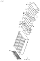
- Fig. 3 is an exploded perspective view illustrating a battery pack according to the embodiment of the present invention
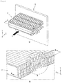
- Fig. 4 is a perspective view illustrating in a case where an external impact is applied to the battery pack in Fig. 3
- Fig. 5 is a perspective view illustrating the cartridge and the cooling cover in Fig. 4
- Fig. 6 is a perspective view illustrating the cooling cover according to the embodiment of the present invention
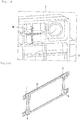
- Fig. 7 is a cross-sectional view illustrating a cross section of the battery pack in Fig. 4 .
- the present invention will be described with reference to the Fig. 3 to Fig. 7 .
- Fig. 3 illustrates a separator 9 and one of a number of battery module 3 groups divided by the separator 9 of components of the battery pack P illustrated in Fig. 1 .
- the plurality of battery modules 3 constituting the group may position between the separator 9 and the end plates 1 and 2.
- the battery pack P illustrated in the FIG. 3 may position in an order of the separator 9, the plurality of battery modules 3, the insulating seat 10 and the end plates 1 and 2 along stacking direction of the plurality of battery modules 3.
- the battery module 3 may further include a secondary cartridge 36.
- Each of the battery module 3 may position in an order of the cooling cover 34, the secondary cartridge 36 and the cartridge 33.
- the battery cell 32 and the buffering member 34 may position in an order of the battery cell 32, the buffering member 34 and the battery cell 32 between the cooling cover 34 and the cartridge 33 of the each battery module as illustrated in fig 2 .
- the number of the battery cell 32 or the buffering member 35 which are included in the each battery module 3 may be changed, if necessary.
- a method of stacking the battery module 3 is that the battery module 3 coupled with the separator 9 and the heat conductive plate 34B of the battery module 3 is disposed to face the separator 9.
- the heat conductive plate 34B of the other battery module 3 which is coupled to the neighboring battery modules 3 may couple in order to be in contact with the cartridge 33 of the battery module 3.
- the heat conductive plate 34B of the other battery module 3 which is coupled to the neighboring battery modules 3 may couple in order to be in contact with the cartridge 33 of the other battery module 3.
- the plurality of battery modules 3 may be stacked in a manner of coupling of the battery module 3, the other battery module, and another battery module 3.
- Fig. 4A is a view illustrating in a state where the battery pack P is received impact from the outside.
- the battery pack P may be mounted on the entire structure as a portion of the entire structure.
- B is capable of performing role of fixing the battery pack P as a fixed rigid block. At this time, when the outer force F is applied from the outside, the fixed battery pack P receives the impact and thus its shape may be deformed.
- Fig. 4B is a view illustrating a shape deformation after the battery pack P is received the impact in the Fig. 4A .
- An area is area that the shape deformation is occurred by the outer impact.
- the positive pole cell lead 31 and the negative pole cell lead 31 of one battery cell 32 included in the battery pack P may be in contact with the cooling cover 34 respectively.
- the cooling cover 34 is made of metal for heat conduction.
- the battery cell 32 and the cooling cover 34 constitutes a closed circuit and thus may be short-circuited.
- a fire may be occurred in the battery pack P.
- the present invention proposes a structure that in a case where the battery pack P receives an impact from the outside, the cooling cover 34 is bent, and thus a distance between and the cooling cover 34 and cell lead 31 of the battery cell 32 is increased. According to the structure described above of the present invention, the distance of the cooling cover 34 and the cell lead 31 of the battery cell 32 is increased and thus the short-circuit of the cell lead 31 and the cooling cover 34 may be prevented.
- Fig. 5 is a view illustrating the cartridge 33 of the battery modules 3 and the cooling cover 34 of the neighboring battery modules 3 stacked to the battery module 3 of the battery module 3 constituting the battery pack P in Fig. 3 .
- the present invention proposes a cartridge 33 which includes means for being bent the cooling cover 34 in a case of the battery pack P receives an impact from the outside.
- the cooling cover 34 is bent by the cartridge 33, and thus a distance between the cooling cover 34 and cell lead(51)of the battery cell 32 may be increased.
- the cartridge 33 according to the embodiment of the present invention does not include the means for bending the cooling cover 34 of the battery module 3 included the cartridge 3 but may include the means for being bent the cooling cover 34 of the other neighboring battery module 3.
- Fig. 5A is an exploded perspective view illustrating the coupling state between the cartridge 33 of the battery module 3 and the cooling cover 34 of the other battery module (3) which is adjacent to the battery stack module (3) with each other.
- Fig 5B is a view illustrating in a case where the cooling cover 34 of the other battery module 3 is received pressure from the cartridge 33 of the battery module 3 and thus is bent.
- the cartridge 33 of the battery module 3 may include a seating portion 33C in which the battery cell 32 is seated.
- a pressing portion 33D is provided on one surface of the seating portion 33C.
- a supporting portion 33E is provided on one surface of the seating portion 33C.
- the pressing portion 33D and the supporting portion 33E may be provided on a same surface of the seating portion 33C.
- the battery cell 32 may be seated to be contacted on one surface of the seated portion 33C.
- the pressing portion 33D and the supporting portion 33E is provided to be spaced apart from each other with a constant distance.
- the pressing portion 33D and the supporting portion 33E is projected to faced each other.
- the pressing portion 33D may include a plurality of projecting portions which are formed on the seating portion 33C.
- the supporting portion 33E may include a plurality of projecting portions which are formed on the seating portion 33C.
- the direction in which the pressing portion 33D is projected may be a direction toward which the cartridge 33 is directed the battery module 3 included and the other neighboring battery modules 3.
- the direction in which the supporting portion 33E is projected may be a direction toward which the cartridge 33 is directed the battery module 3 included and the other neighboring battery modules 3.
- the pressing portion 33D is formed to be lengthened in the perpendicular direction to the longitudinal direction of the cartridge 33.
- the supporting portion 33E is formed to be lengthened in the perpendicular direction to the longitudinal direction of the cartridge 33.
- the pressing portion 33D may have a rib shape.
- the pressing portion 33D may have a plurality of rib shapes.
- the supporting portion 33E may be a rib shape.
- the supporting portion 33E may have a plurality of rib shapes.
- the pressing portion 33D and the supporting portion 33E may have the same shape with each other.
- the pressing portion 33D of the battery module 3 may be in contact with one end of the cooling cover 34 which is included in the other neighboring battery module 33 of the battery module 3.
- the supporting portion 33E of the battery module 3 may be in contact with the other end of the cooling cover 34 which is included in the other neighboring battery module 33 of the battery module 3.
- the height that the pressing portion 33D of the battery module 3 is projected from the cartridge 33 is equal to the thickness of a heat conductive plate 34B and is greater than the thickness of the heat conductive plate 34B.
- the height that the supporting portion 33E of the battery module 3 is projected from the cartridge 33 is equal to the thickness of a heat conductive plate 34B and is greater than the thickness of a heat conductive plate 34B.
- the cooling cover 34 of the other neighboring battery module 3 of the battery module 3 may be positioned between the pressing portion 33D and the supporting portion 33E of the battery module 3.
- the gap that pressing portion 33D and the supporting portion 33E of the battery module 3 is spaced apart from each other may be only a length of the heat conductive plate 34B of the cooling cover 34 included in the other neighboring battery modules 3 of the battery module 3.
- the cooling cover 34 of the other neighboring battery modules 3 of the battery module 3 may be restricted in the longitudinal direction of the cooling cover 34 due to the pressing portion 33D of the battery module 3.
- the cooling cover 34 of the battery module 3 and the other neighboring battery modules 3 is restricted in the longitudinal direction of the cooling cover 34 due to the supporting portion 33E of the battery module 3.
- the pressing portion 33D of the battery module 3 may press one end or one side of the cooling cover 34 of the other neighboring battery module 3 of the battery module 3.
- the cooling cover 34 of the other battery module 3 receives pressure from the pressing portion 33D and the battery module 3 and may bend as illustrated in Fig. 5B .
- the pressing portion 33D of the battery module 3 may press one end or one side of the cooling cover 34 of the other neighboring battery module 3 of the battery module 3.
- the supporting portion 33E of the battery module 3 may support the other end or the other side of the cooling cover 34 of the other neighboring battery module 33 of the battery module 3.
- the one end of the cooling cover 34 may is one end of the heat conductive plate 34B.
- the other end of the cooling cover 34 may is the other end of the heat conductive plate 34B.
- the one side of the cooling cover 34 may is one side of the heat conductive plate 34B.
- the other side of the cooling cover 34 may is the other side of the heat conductive plate 34B.
- the one end of the cooling cover 34 may be perpendicular to the longitudinal direction of the cooling cover 34.
- the other end of the cooling cover 34 may be perpendicular to the longitudinal direction of the cooling cover 34.
- the one end or the one side of the heat conductive plate 34B of the cooling cover 34 may be perpendicular to the longitudinal direction of the cooling cover 34.
- the other end or the other side of the heat conductive plate 34B of the cooling cover 34 is perpendicular to the longitudinal direction of the cooling cover 34.
- the cooling cover 34 of the other battery module 3 receives pressure from the pressing portion 33D of battery module 3 and may be supported from the supporting portion 33E, and the pressure in the transverse direction may act to the cooling cover 34.
- the cooling cover 34 received the pressure in the transverse direction may be bent as illustrated in Fig. 5B .
- the gap between the one end and the other end of the cooling cover 34 may be decreased than that of before the cooling cover 34 is bent.
- the gap between the one side and the other side of the cooling cover 34 may be decreased than that of before the cooling cover 34 is bent.
- the gap between the one end and the other end of the cooling cover 34 may be decreased than the length of the battery cell 32.
- the gap between the one side and the other side of the cooling cover 34 may be more decreased than the length of the battery cell 32.
- a bending line perpendicular to the longitudinal direction of the cooling cover 34 may be formed in the heat conductive plate 34B of the cooling cover 34.
- a bending line perpendicular to the longitudinal direction of the cooling cover 34 may be formed in the fastening plate 34C of the cooling cover 34.
- the cooling cover 34 may further include a hole except for the coupling groove 34A of the projection 36A for coupling with the cartridge 33.
- the cooling cover 34 includes the hole and thus may be more easily bent.
- the hole may has a long hole shape.
- the cooling cover 34 may include a plurality of holes.
- the heat conductive plate 34B may include a hole 34E.
- the hole 34E which is formed on the heat conductive plate 34B is formed to be lengthened and thus may have a long hole shape.
- the hole 34E formed on the heat conductive plate 34B is a long hole shape and may be positioned to be perpendicular to the longitudinal direction of the heat conductive plate 34B.
- the hole 34E formed on the heat conductive plate 34B is a long hole shape and may be positioned to be perpendicular to the longitudinal direction of the cartridge 33.
- the hole 34E formed on the heat conductive plate 34B may be lengthened to be vertical to the longitudinal direction of the cooling cover 34.
- the hole 34E formed on the heat conductive plate 34B may be lengthened to be vertical to the longitudinal direction of the heat conductive plate 34B.
- the heat conductive plate 34B may include a plurality of holes 34E.
- the plurality of holes 34E may position in a state of forming a row.
- the plurality of holes 34E are spaced apart in the perpendicular direction to the longitudinal direction of the heat conductive plate 34B.
- the plurality of the holes 34E are spaced apart in the perpendicular direction to the longitudinal direction of the heat conductive plate 34B.
- the heat conductive plate 34B may be symmetrical with respect to a row formed by a plurality of holes 34E.
- the heat conductive plate 34B may be symmetrical with respect to a row formed by a plurality of holes 34E.
- the cooling cover 34 may be symmetrical with respect to a row formed by a plurality of holes 34E.
- the cooling cover 34 may include the pair of the fastening plates 34C.
- a hole 34D may be formed on any fastening plate 34C of the pair of fastening plates 34C.
- the hole 34D formed on the pair of fastening plates 34C may be symmetrical with each other.
- the hole 34D which is formed on the fastening plate 34C is formed to be lengthened and thus may have a long hole shape.
- the hole 34D formed on the fastening plate 34C is a long hole shape and may be positioned to be perpendicular to the longitudinal direction of the fastening plate 34C.
- the hole 34D formed on the fastening plate 34C is a long hole shape and may be positioned to be perpendicular to the longitudinal direction of the cartridge 33.
- the hole 34D formed on the fastening plate 34C may be lengthened to be vertical to the longitudinal direction of the cooling cover 34.
- the hole 34D formed on the fastening plate 34C may be lengthened to be vertical to the longitudinal direction of the fastening plate 34C.
- the fastening plate 34C may include a plurality of holes 34D.
- the plurality of holes 34D may be positioned in a state of forming a row.
- the plurality of holes 34D may be spaced apart in the perpendicular direction to the longitudinal direction of the fastening plate 34C.
- the plurality of holes 34D are spaced apart in the perpendicular direction to the longitudinal direction of the cooling cover 34.
- the fastening plate 34C may be symmetrical with respect to a row formed by a plurality of holes 34D.
- Fig. 7 is a cross-sectional view illustrating a cross section of the battery pack P in Fig. 4 .
- Fig. 7A is a cross-sectional view of the G-G line and illustrates a state before the battery pack P receives the impact.
- Fig. 7B is a cross-sectional view of the H-H line and illustrates a state after the battery pack P receives the impact.
- the pressing portion 33D of the cartridge 33 presses one end or one side of the cooling cover 34 in the X direction.
- the support portion 33E of the cartridge 33 may support one end or one side of the cooling cover 34 in the opposite dirction of the X direction.
- the cooling cover 34 When the external force is applied to the battery pack P in the X direction, the cooling cover 34 may be bent as illustrated in Fig. 7B due to the pressing portion 33D of the cartridge 33.
- the cooling cover 34 When the external force is applied to the battery pack P in the X direction, the cooling cover 34 may be bent as illustrated in Fig. 7B due to the pressing portion 33D and the supporting portion 33E of the cartridge 33.
- the cooling cover 34 When the cooling cover 34 is bent as illustrated in Fig. 7B , the cooling cover 34 and the cell lead 31 is not in contact with each other to be space apart from each other. In other words, even if the battery pack P receives an impact from the outside, the cooling cover 34 and cell lead 31 is not short-circuited and thus the danger of overheat or fire may be reduced.
- the cell lead 31 of the battery cell 32 receives the pressure in the X direction.
- the cell lead 31 may be crumpled as illustrated in Fig. 7B .
- the cell lead 31 receives the external force and thus may be crumpled.
- the crumpled cell lead 31 does not have a sufficient space to escape, the cell lead 31 may be lost.
- the length of the cell lead 31 may be decreased and there is a danger that the cooling cover 34 and the battery is short-circuited.
- the present invention proposes the space in which the crumpled cell lead 31 is to be escaped so that the cell lead 31 is not lost due to the external force. Therefore, the cartridge 33 according to the embodiment of the present invention may include a stepped portion 33F.
- the stepped portion 33F may provide the space in which the crumpled cell lead 31 escapes in a case where an external force is applied to the battery pack P.
- the cell lead 31 may move in the stacking direction of the battery cell 32 due to the space in which the stepped portion 33F provides.
- the cell lead 31 may move in the perpendicular direction to the stacking direction of the battery cell 32 due to the space in which the stepped portion 33F is provided.
- the cell lead 31 may move in the stacking direction of the battery module 3 due to the space in which the stepped portion 33F may be provided.
- the cell lead 31 may move in the perpendicular direction to the stacking direction of the battery module 3 due to the space in which the stepped portion 33F provided.
- the cartridge 33 of the battery module 3 may include a seating portion 33C in which the battery cell 32 is seated.
- a stepped portion 33F is provided on one surface of the seating portion 33C.
- the battery cell 32 may be seated to be contacted on the one surface of the seated portion 33C.
- the stepped portion 33F and the pressing portion 33D may be formed on a same surface of the seated portion 33C.
- the stepped portion 33F may be formed in parallel with the pressing portion 33D.
- the stepped portion 33F may be formed in parallel with the supporting portion 33E.
- the stepped portion 33F may be formed to face at least a portion of the cell lead 31.
- the stepped portion 33F included in the cartridge 33 of the battery module 3 may be formed to be parallel with the cooling cover 34 of the other neighboring battery module 33 to the battery module 3.
- the stepped portion 33F included in the cartridge 33 of the battery module 3 may be formed to be parallel with the heat conductive plate 34B of the other neighboring battery module 33 of the battery module 3.
- the step of the stepped portion 33F is formed to be smaller than the thickness of the cartridge 33.
- the step of the stepped portion 33F is formed to be smaller than the thickness of the seating portion 33C of the cartridge 33.
- the stepped portion 33F may be formed on the same surface with one surface of the seating portion 33C on which the pressing portion 33D is formed.
- the stepped portion 33F may be formed in the outer side of the pressing portion 33D.
- the stepped portion 33F may be formed on the same surface with one surface of the seating portion 33C on which the supporting portion 33E is formed.
- the stepped portion 33F may be formed in the outside of the supporting portion 33E.
- the stepped portion 33F is formed to be lengthened in the perpendicular direction to the longitudinal direction of the cartridge 33.
- the width of the stepped portion 33F may be equal to the width of the cell lead 31.
- the width of the stepped portion 33F may be greater than the width of the cell lead 31.
- the gap between the stepped portion 33F formed on the outside of the pressing portion 33D and the stepped portion 33F formed on the outside of the supporting portion 33E may be greater than the gap between the pressing portion 33D and the supporting portion 33E.
- the gap between the stepped portion 33F formed on the outside of the pressing portion 33D and the stepped portion 33F formed on the outside of the supporting portion 33E may be greater than the length of the cooling cover 34.
- the battery module 3 may further include a secondary cartridge 36. Each of the battery module 3 may position in an order of the cooling cover 34, the secondary cartridge 36 and the cartridge 33.
- the battery cell 32 and the buffering member 34 may position in an order of the battery cell 32, the buffering member 34 and the battery cell 32 between the cooling cover 34 and the cartridge 33 of the each battery module 3.
- the secondary cartridge 36 may position in parallel with the cartridge 33.
- the secondary cartridge 36 may position in parallel with the cooling cover 34.
- the secondary cartridge 36 may position toward one end or one side of the buffering member 35 positioned between the battery cell 32 and the battery cell 32, as illustrated in Fig. 7A .
- the secondary cartridge 36 may further include a projection 36A toward one end or one side of the buffering member 35 positioned between the battery cell 32 and the battery cell 32, as illustrated in Fig. 7A .
- the battery cell 32 and the battery cell 32 may surface-contact.
- the secondary cartridge 36 may position toward the contact surface between the battery cell 32 and the battery cell 32.
- the secondary cartridge 36 may further include a projection 36A toward the contact portion between the battery cell 32 and the battery cell 32.
- the pressing portion 33D of the cartridge 33 presses one end or one side of the cooling cover 34 in the X direction.
- the secondary cartridge 36 may enter toward the buffering member 35.
- the projection 36A of the secondary cartridge 36 may position between the battery cell 32 and the battery cell 32 as illustrated in the FIG. 7B .
- the buffering member 35 is not provided between the battery cell 32 and the battery cell 32 and the battery cell 32 and the battery cell 32 and the battery cell 32 may surface-contact.
- the secondary cartridge 36 may enter toward the contact surface between the battery cell 32 and the battery cell 32.
- the projection 36A of the secondary cartridge 36 may position between the battery cell 32 and the battery cell 32.
- the projection 36A of the secondary cartridge 36 may position between the battery cell 32 and the battery cell 32. When an external force is applied to the battery pack P in the X direction, the projection 36A of the secondary cartridge 36 may press the battery cell 32 contacting the projection 36A.
- the projection 36A of the secondary cartridge 36 may press the two battery cell 32 contacting the projection 36A in the mutually opposite directions according to Y direction.
- the secondary cartridge 36 may press the two battery cell 32 according to the Y direction and thus the cooling cover 34 and the cartridge 33 may contact without misaligning to each other, even if the external force is applied to the battery pack P. Accordingly, the cooling cover 34 may be more easily bent by the secondary cartridge 36.
- Fig. 8 is a front view illustrating a battery cell according to an embodiment of the present invention
- Fig. 9 is an enlarged view illustrating the cooling cover and the battery cell contacting the cooling cover
- Fig. 10 is a perspective view illustrating a cartridge according to an embodiment of the present invention
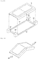
- Fig. 11 is a perspective view illustrating a separator according to an embodiment of the present invention
- Fig. 12 is a perspective view illustrating an insulating sheet according to an embodiment of the present invention.
- the battery cell 32 may include a battery cell main body 32A in which a charge is stored, a cell lead 31 which is connected to the battery cell main body 32A, and an exterior material 32B.
- the exterior material 32B performs a role that insulates the battery cell main body 32A.
- the exterior material 32B may surround the battery cell main body 32A and may surround at least a portion of the cell lead 31.
- a C area in which the exterior material 32B overlaps with the edge of the battery cell 32 may be formed.
- the C area may be formed on the four portions.
- the C area may be a corner portion or an edge portion of an outer appearance of the battery cell 32.
- the cooling cover 34 may generate a sharp corner due to the production process. With reference to Fig. 9 , the sharp corner may be a J area.
- the cooling cover 34 and the battery cell 32 may be in surface-contact with each other. Further, the battery pack P may be mounted on the entire structure as a portion of the entire structure, and thus the battery pact P receives vibration and impact. At this time, the C area of the battery cell 32 which is in surface-contact with the cooling cover 34 makes friction with the J area of the cooling cover 34. Alternatively, the C area of the battery cell 32 which is in surface-contact with the cooling cover 34 makes repeatedly friction and separation with the J area of the cooling cover 34.
- the C region of the battery cell 32 may be damaged or torn.
- the battery cell main body 32A is not insulated.
- the insulation of the battery cell 32, the battery module 3 or the battery pack P may be destroyed. Accordingly, a structure which allows the C area of the battery cell 32 and the J area of the cooling cover 34 to be appropriately separated or spaced apart from each other is needed.
- Fig. 10A is a perspective view illustrating a cartridge 33 according to an embodiment of the present invention
- the cartridge 33 of the battery module 3 may include a seating portion 33C in which the battery cell 32 is seated.
- a projection portion 33G may be provided in one surface of the seating portion 33C.
- the projection portion 33G may be formed on one surface of the seating portion 33C on which the pressing portion 33D is formed.
- the projection portion 33G may be formed on one surface of the seating portion 33C on which the supporting portion 33E is formed.
- the battery cell 32 may be seated to be contacted on the one surface of the seated portion 33C.
- the projection portion 33G may be formed on the other surface of the seated portion 33C.
- an E area may be formed on the edge of the cartridge 33 or the seating portion 33C.
- the E area may be formed on the four portions.
- the E area may be the edge portion or the corner portion of a seating portion 33C or the cartridge 33.
- the projection portion 33G may be formed on the E area. A plurality of projection portions 33G may be formed.
- the projection portion 33G formed on the E area of the seating portion 33C or the cartridge 33 allows the C area of the battery cell 32 which is in surface-contact with the cooling cover 34 of the other neighboring battery module 3 to be bent or folded.
- the C area of the battery cell 32 which is in surface-contact with the cooling cover 34 When the C area of the battery cell 32 which is in surface-contact with the cooling cover 34 is bent or fold, the C area may be separated or spaced apart from the J area of the cooling cover 34 and thus the risk that the outer appearance of the battery cell 32 is damaged may be reduced.
- the projection portion 33G may be formed as Fig. 10C .
- the cartridge 33 of the related art is carried out in a state where the projection portion 33G is not formed, as illustrated in Fig. 10B .
- the cartridge 33 according to the embodiment of the present invention may form the projection portion 33G as illustrated in Fig. 10C .
- the projection portion 33G may have a rib shape.
- Fig. 11A is a perspective view illustrating a separator 9 according to an embodiment of the present invention.
- the separator 9 may be in surface-contact with the cooling cover 34.
- the separator 9 may be in surface-contact with the a pair of cooling covers 34 with the separator 9 being disposed between the cooling covers 34.
- the separator 9 may be in surface-contact with the heat conductive plate 34B of the cooling cover 34.
- the separator 9 may be in surface-contact with the a pair of heat conductive plates 34B with the separator 9 being disposed between the heat conductive plates 34B.
- the projection portion 9A may be formed on one surface of the separator 9. Further, the projection portion 9A may be formed on the other surface of the separator 9.
- a D area may be formed on the edge of the separator 9, with reference to Fig. 11 .
- the D area may be formed on the four portions.
- the D area may be a corner portion or an edge portion of the separator 9.
- the projection portion 9A may be formed on the D area.
- a plurality of projection portions 9A may be formed. Further, the projection portion 9A may be formed on the opposite surface of the D area.
- the projection portion 9A formed on the D area of the separator 9 allows the C area of the battery cell 32 which is in surface-contact with the cooling cover 34 of the neighboring battery module 3 of the separator 9 to be bent or folded.
- the C area of the battery cell 32 which is in surface-contact with the cooling cover 34 When the C area of the battery cell 32 which is in surface-contact with the cooling cover 34 is bent or fold, the C area may be separated or spaced apart from the J area of the cooling cover 34 and thus the risk that the outer appearance of the battery cell 32 is damaged may be reduced.
- the projection portion 9A may be formed as Fig. 11A to Fig. 11E .
- the separator 9 of the related art is carried out in a state where the projection portion 9A is not formed, as illustrated in Fig. 11B .
- the separator 9 according to the embodiment of the present invention may be formed the projection portion 9A which is parallel in the longitudinal direction of the separator 9 as illustrated in Fig. 11C .
- the projection portion 9A may have a rib shape.
- the cartridge 9 may be formed the projection portion 9A which is parallel in the longitudinal direction of the separator 9 and the projection portion 9A which is perpendicular to the longitudinal direction of the separator 9 as illustrated in Fig. 11d .
- the projection portion 9A may have a rib shape.
- the cartridge 9 may be formed the projection portion 9A which is parallel in the longitudinal direction of the separator 9 and the projection portion 9A which is perpendicular to the longitudinal direction of the separator 9 as illustrated in Fig. 11e . Further, the projection portion 9A parallel with the longitudinal direction of the separator 9 and the projection portion 9A perpendicular to the longitudinal direction of the separator 9 may cross to each other.
- the projection portion 9A may have a rib shape.
- Fig. 12A is a perspective view illustrating an insulating sheet 10 according to an embodiment of the present invention.
- the insulation sheet 10 may position between the end plates 1 and 2 and the neighboring battery module 3 of the end plates 1 and 2. Further, the insulation sheet 10 may position between the end plates 1 and 2 and the cooling cover 34 of the neighboring battery module 3 of the end plates 1 and 2.
- the insulation sheet 10 may be in surface-contact with the cooling cover 34. Further, the insulation sheet 10 may be in surface-contact with the heat conductive plate 34B of the cooling cover 34.
- the projection portion 10A may be formed on one surface of the insulation sheet 10.
- a K area may be formed on the edge of the insulation sheet 10, with reference to Fig. 12a .
- the K area may be formed on the four portions.
- the K area may be a corner portion or an edge portion of the insulation sheet 10.
- the projection portion 9A may be formed on the K area.
- a plurality of projection portions 10A may be formed.
- the projection portion 10A formed on the K area of the insulation sheet 10 allows the C area of the battery cell 32 which is in surface-contact with the cooling cover 34 of the neighboring battery module 3 of insulation sheet 10 to be bent or folded.
- the C area of the battery cell 32 which is in surface-contact with the cooling cover 34 When the C area of the battery cell 32 which is in surface-contact with the cooling cover 34 is bent or fold, the C area may be separated or spaced apart from the J area of the cooling cover 34 and thus the risk that the outer appearance of the battery cell 32 is damaged may be reduced.
- the projection portion 10A may be formed as Fig. 12C .
- the insulation sheet 10 of the related art is carried out in a state where the projection portion 10A is not formed, as illustrated in Fig. 12B .
- the insulation sheet 10 according to the embodiment of the present invention may form the projection portion 10A as illustrated in Fig. 12c .
- the projection portion 10A may have a rib shape.
- the projection portion 10A formed on one surface of the insulation sheet 10 may be projected in a convex shape and the other surface of the insulation sheet 10 is recessed in a concave shape.
- Fig. 13A is an exploded perspective view illustrating a cartridge of a battery module and a cooling cover coupled with cartridge of the battery module according to another embodiment of the present invention.
- Fig 13B is a view illustrating in a case where the cooling cover 34' of the other battery module 3' according to the other embodiment of the present invention receives pressure from the cartridge 33' of the battery module 3' and thus is bent.
- the cartridge 33' includes the means for bending the cooling cover 34' of the battery module 3' including the cartridge 33 but does not include the means for bending the cooling cover 34' of the neighboring battery module 3'.
- the cartridge 33' of the battery module 3' may include a seating portion 33C' in which the battery cell 32' is seated.
- a pressing portion 33D' is provided in one surface of the seating portion 33C'.
- a supporting portion 33E' may be provided in one surface of the seating portion 33C'.
- the pressing portion 33D' and the supporting portion 33E' may be provided in one surface of the seating portion 33C'.
- the battery cell 32' may be seated to be contacted on the one surface of the seated portion 33C'.
- the pressing portion 33D' may be formed on one surface of the seated portion 33C'.
- the battery cell 32' may be seated to be contacted on the one surface of the seated portion 33C'.
- the supporting portion 33D' may be formed on one surface of the seated portion 33C'.
- the pressing portion 33D' and the supporting portion 33E' are provided to be spaced apart from each other.
- the pressing portion 33D' and the supporting portion 33E' are projected to faced each other.
- the pressing portion 33D' may include a plurality of projecting portions which are formed on the seating portion 33C'.
- the supporting portion 33E' may include a plurality of projecting portions which are formed on the seating portion 33C'.
- the pressing portion 33D' is formed to be lengthened in the perpendicular direction to the longitudinal direction of the cartridge 33'.
- the supporting portion 33E' is formed to be lengthened in the perpendicular direction to the longitudinal direction of the cartridge 33'.
- the pressing portion 33D' may have a rib shape.
- the pressing portion 33D' may have a plurality of rib shapes.
- the supporting portion 33E' may be a rib shape.
- the supporting portion 33E' may have a plurality of rib shapes.
- the pressing portion 33D' and the supporting portion 33E' may have the same shape with each other.
- the pressing portion 33D' of the battery module 3' may be in contact with one end of the cooling cover 34 which is included in the battery module 3.
- the supporting portion 33E' of the battery module 3' may be in contact with the other end of the cooling cover 34 which is included in the battery module 3'.
- the cooling cover 34 of the battery module 3' may be positioned between the pressing portion 33D' and the supporting portion 33E' of the battery module 3'.
- the gap that pressing portion 33D' and the supporting portion 33E' of the battery module 3' is spaced apart from each other may be only a length of the heat conductive plate of the cooling cover 34 included in the battery module 3'.
- the cooling cover 34 included in the battery module 3' may be restricted in the longitudinal direction of the cooling cover 34 due to the pressing portion 33D' of the same battery module 3'.
- the battery module 3' and the included cooling cover 34' may be restricted in the longitudinal direction of the cooling cover 34 due to the supporting portion 33E' of the same battery module 3'.
- the pressing portion 33D' of the battery module 3' may press one end or one side of the cooling cover 34 of the same battery module 3'.
- the cooling cover 34 of the battery module(3') receiving the pressure from the pressing portion 33D' of the battery module 3' may be bent as described in Fig. 13b .
- the pressing portion 33D' of the battery module 3' may press one end or one side of the cooling cover 34 in the same battery module 3'.
- the supporting portion 33E' of the battery module 3' may support the other end or the other side of the cooling cover 34' of the same battery module 3'.
Abstract
Description
- The present invention relates to a battery pack, and more specifically a battery pack which includes a structure preventing a battery cell and a cooling cover from being short-circuited in a case where impact is applied to the battery pack.
- The battery pack is a device that a plurality of battery cells for supplying power to the outside are assembled as an unit and is applied to and used to various industrial fields, such as mobile terminals, home appliances and an automobile.
- Particularly, the battery pack may be mounted on and used to an electric vehicle traveling by a driving force outputted from a driving motor. The battery pack may be configured by being coupled a plurality of battery modules with each other. Each of the plurality of battery modules may includes at least one battery cells.
- A cell lead may be includes in each of the battery cells.
- The battery pack may further include a bus bar for connecting to the cell lead. The battery pack may connect to the plurality of battery cells in series or in parallel by the bus bar.
- Meanwhile, the battery pack may be a cooling cover for cooling heat generating in the battery cell.
- The battery pack may be deformed its shape in a case where impact is applied from the outside to the battery pack. In this case, the battery cell is short-circuited with the cooling cover by the impact.
- In a case where the battery cell and the cooling cover is short-circuited with respect to each other, a fire may be generated. Accordingly, a structure that prevents the short-circuit is needed.
- The present invention provides a battery pack in which a plurality of battery modules are stacked. At least one battery module of the plurality of battery modules includes at least one battery cell having a cell lead, a cartridge on which the battery cell is mounted, and a cooling cover which is coupled to the cartridge and covers the battery cell. The cartridge includes a seating portion on which the battery cell is seated and a pressing portion which is formed on the seating portion and presses one end of the cooling cover of the other neighboring battery module when an external force is applied to the seating portion.
-
-
Fig. 1 is a perspective view illustrating a battery pack according to an embodiment of the present invention, -
Fig. 2 is a cross-sectional view illustrating the battery module and a connecting board assembly inFig. 1 , -
Fig. 3 is an exploded perspective view illustrating a battery pack according to the embodiment of the present invention, -
Fig. 4 is a perspective view illustrating in a case where an external impact is applied to the battery pack inFig. 3 , -
Fig. 5A is a perspective view illustrating a cartridge and a cooling cover inFig. 4 , -
Fig 5B is a perspective view illustrating in a case where the cooling cover inFig. 5A is bent, -
Fig. 6 is a perspective view illustrating the cooling cover according to the embodiment of the present invention, -
Fig. 7 is a cross-sectional view illustrating a cross section of the battery pack inFig. 4 , -
Fig. 8 is a front view illustrating a battery cell according to an embodiment of the present invention, -
Fig. 9 is an enlarged view illustrating the cooling cover and the battery cell contacting the cooling cover, -
Fig. 10A is a perspective view illustrating the cartridge according to an embodiment of the present invention, -
Fig. 10B is an enlarged view of an E area according to the related art, -
Fig. 10C is an enlarged view illustrating an embodiment of the E area according of the present invention, -
Fig. 11A is a perspective view illustrating a separator according to an embodiment of the present invention, -
Fig. 11B is an enlarged view a D area according to the related art, -
Fig. 11C is an enlarged view illustrating an embodiment of the D area according of the present invention, -
Fig. 11D is an enlarged view illustrating another embodiment of an D area according of the present invention, -
Fig. 11E is an enlarged view illustrating another embodiment of an D area according of the present invention, -
Fig. 12A is a perspective view illustrating an insulating sheet according to an embodiment of the present invention, -
Fig. 12B is an enlarged view of a K area according to the related art, -
Fig. 12C is an enlarged view illustrating an embodiment of a K area according of the present invention, -
Fig. 13A is a perspective view illustrating a cartridge of a battery module and a cooling cover of the same battery module according to another embodiment of the present invention, and -
Fig 13B is a perspective view illustrating in a case where the cooling cover inFig. 13A is bent. - Hereinafter, a specific embodiment of the present invention will be described in detail with reference to the drawing.
-
Fig. 1 is a perspective view illustrating a battery pack according to an embodiment of the present invention andFig. 2 is a cross-sectional view illustrating the battery module and a connecting board assembly inFig. 1 . - The battery pack P may include a pair of
end plates battery modules 3 which are disposed between the pair ofend plates - The plurality of
battery modules 3 may be disposed to be stacked between the pair ofend plate battery modules 3 may be disposed to be stacked between the pair ofend plate - The plurality of
battery modules 3 may be divided into a number ofgroups separator 9. The battery pack P may include aseparator 9 which is divided into agroup 3A and theother group 3B from a number ofgroups - The
battery module 3 may include abattery cell 32 having acell lead 31, as illustrated inFig. 2 . Thecell lead 31 may be an positive pole cell lead or a negative pole cell lead which is provided in thebattery cell 32. - The
battery module 3 may further include acartridge 33 and acooling cover 34. Thebattery cell 32 may be disposed between thecartridge 33 and thecooling cover 34. - The
battery module 3 may include at least twobattery cell 32. Thebattery module 3 may further include a bufferingmember 35 disposed between the twobattery cells 32. The bufferingmember 35 may be made of an elastic material. - In a case where the
battery module 3 includes a pair ofbattery cells 32, any one of the pair ofbattery cells 32 may be seated to be in contact with thecartridge 33 and the other one thereof may be seated to be in surface-contact with thecooling cover 34. - A
projection 33A may be formed on the any one of thecartridge 33 and thecooling cover 34, and aprojection coupling hole 34A in which the projection is inserted and coupled with each other may be formed on the other one thereof. - The cooling
cover 34 may be include a heatconductive plate 34B which faces thebattery cell 32 and afastening plate 34C which is bent from the heatconductive plate 34B and is detachably coupled with thecartridge 33. - The heat
conductive plate 34B may include a flat plate portion which is in surface-contact with thebattery cell 32. - A pair of
fastening plates 34C may be provided on the heatconductive plate 34B. In a case where aprojection 33A may be provided on thefastening plate 34C, aprojection coupling hole 34A in which theprojection 33A is inserted and coupled with each other may be provided in thecartridge 33. Contrary, in a case where theprojection coupling hole 34A may be provided in thefastening plate 34C, theprojection 33A which is inserted into theprojection coupling hole 34A and coupled with each other may be provided in thecartridge 33. - An
opening portion 33B into which the cooling cover of the other neighboring battery module is inserted is provided on thecartridge 33, as illustrated inFig. 2 . - At the time of coupling the
cartridge 33 and thecooling cover 34, the coolingcover 34 and any one of the pair of thebattery cells 32, the bufferingmember 35 and the other one of the pair of thebattery cells 32, and thecartridge 33 are coupled with each other and thus may become abattery module 3. - Meanwhile, at least a portion of the
cell lead 31 of thebattery cell 32 is positioned at the outside of thecartridge 33 and thecooling cover 34 and thecell lead 31 may be connected to a connectingboard assembly 4. - The battery pack P may further include a connecting
board assembly 4 to which a plurality ofbattery modules 3 are connected. The connectingboard assembly 4 may be connected with thecell lead 31 and may connect with the plurality ofbattery cells 32 in series or in parallel. - The battery pack P may include a
bus bar 5 to which thecell lead 31 is connected, and a connectingboard 6 on which thebus bar 5 is mounted, as illustrated inFig. 2 . The battery pack P may further include anouter cover 7 which covers the connectingboard 6 and thebus bar 5. - The
bus bar 5 may include afastening portion 51 and a celllead connecting portion 52 which is provided on thefastening portion 51 and to which the cell lead(31) is connected. - The
fastening portion 51 may be fastened to the connectingboard 6 using a latching portion such as a hook or a fastening member(54) such as a screw (hereinafter, referred to as a fastening member). In a case where thefastening portion 51 is fastened to the connectingboard 6 by thefastening member 54, a throughhole 55 through which thefastening member 54 is passed may be provided on thefastening portion 51 and a fasteningmember fastening portion 56 to which thefastening member 54 is fastened may be disposed on the connectingboard 6. The fasteningmember fastening portion 56 may include a fastening boss through which thefastening member 54 is screw-fastened or nut. If thefastening portion 51 is fastened via the latching portion, a hook is form at any one of thefastening portion 51 and the connectingboard 6 and a hook latching portion which the hook is latched to. On the other hand, thefastening portion 51 and the connectingboard 6 can be fastened by clamping thefastening portion 51 and the connectingboard 6 with one or more ends by a clamp member. - A plurality of cell leads connecting
portions 52 are provided to thefastening portion 51 and more than one pair of celllead connecting portions 52 are provided thereto. - The
bus bar 5 may be is It may be connected to be energized with a pair of cell leads 31. The pair of cell leads 31 is electrically connected through thebus bar 5. The pair of celllead connecting portions 52 are provided to be face each other. The pair of celllead connecting portions 52 are bent to be perpendicular to thefastening portion 51. - The
bus bar 5 may be connected to be energized to thecell lead 31 of theother battery cell 32. Thecell lead 31 of the any onebattery cell 32 of the plurality ofbattery cells 32 may be connected with any one of the pair of celllead connecting portion 52. Thecell lead 31 of any theother battery cell 32 of the plurality ofbattery cells 32 may be connected with the other one of the pair of celllead connecting portions 52. - Preferably, the
cell lead 31 and thebus bar 5 is joined to be capable of transmitting the sufficient power while thecell lead 31 is may be firmly connected to thebus bar 5. Further, preferably thecell lead 31 is joined to thebus bar 5 in an ultrasonic welding or a vibration welding manner. - A plurality of
bus bars 5 may be installed to the connectingboard 6. A plurality ofbus bars 5 may be disposed to be spaced apart in a parallel direction to a stacking direction of thebattery module 3 and each other. - The connecting
board 6 may be configured to be a plate shape body which is lengthened in the parallel direction to the stacking direction of the plurality ofbattery modules 3. - A through
hole 61 through which thecell lead 31 of thebattery cell 32 is passed is provided on the connectingboard 6. - Meanwhile, a
space 71 in which thebus bar 5 is housed is provided between the connectingboard 6 and theouter cover 7. Thebus bar 5 is housed in thespace 71 between the connectingboard 6 and theouter cover 7 in a state where thebus bar 5 is mounted on the connectingboard 6. - At the time of assembly of the battery pack P, the
bus bar 5 may be joined with thecell lead 31 of thebattery cell 32 in a state where thebus bar 5 is fastened to the connectingboard 6. - The
outer cover 7 may be fastened to at least one of theend plates Fig. 1 , theseparator 9 and the connectingboard 6. - The
outer cover 7 is capable to protecting thebus bar 5 mounted on the connectingboard 6. Theouter cover 7 is capable to protecting thecell lead 31 positioning in thespace 71. -
Fig. 3 is an exploded perspective view illustrating a battery pack according to the embodiment of the present invention,Fig. 4 is a perspective view illustrating in a case where an external impact is applied to the battery pack inFig. 3 ,Fig. 5 is a perspective view illustrating the cartridge and the cooling cover inFig. 4 ,Fig. 6 is a perspective view illustrating the cooling cover according to the embodiment of the present invention, andFig. 7 is a cross-sectional view illustrating a cross section of the battery pack inFig. 4 . The present invention will be described with reference to theFig. 3 to Fig. 7 . -
Fig. 3 illustrates aseparator 9 and one of a number ofbattery module 3 groups divided by theseparator 9 of components of the battery pack P illustrated inFig. 1 . The plurality ofbattery modules 3 constituting the group may position between theseparator 9 and theend plates - The battery pack P illustrated in the
FIG. 3 may position in an order of theseparator 9, the plurality ofbattery modules 3, the insulatingseat 10 and theend plates battery modules 3. - The
battery module 3 may further include asecondary cartridge 36. Each of thebattery module 3 may position in an order of thecooling cover 34, thesecondary cartridge 36 and thecartridge 33. Thebattery cell 32 and the bufferingmember 34 may position in an order of thebattery cell 32, the bufferingmember 34 and thebattery cell 32 between the coolingcover 34 and thecartridge 33 of the each battery module as illustrated infig 2 . The number of thebattery cell 32 or the bufferingmember 35 which are included in the eachbattery module 3 may be changed, if necessary. - A method of stacking the
battery module 3 is that thebattery module 3 coupled with theseparator 9 and the heatconductive plate 34B of thebattery module 3 is disposed to face theseparator 9. - The heat
conductive plate 34B of theother battery module 3 which is coupled to the neighboringbattery modules 3 may couple in order to be in contact with thecartridge 33 of thebattery module 3. The heatconductive plate 34B of theother battery module 3 which is coupled to the neighboringbattery modules 3 may couple in order to be in contact with thecartridge 33 of theother battery module 3. - The plurality of
battery modules 3 may be stacked in a manner of coupling of thebattery module 3, the other battery module, and anotherbattery module 3. -
Fig. 4A is a view illustrating in a state where the battery pack P is received impact from the outside. The battery pack P may be mounted on the entire structure as a portion of the entire structure. B is capable of performing role of fixing the battery pack P as a fixed rigid block. At this time, when the outer force F is applied from the outside, the fixed battery pack P receives the impact and thus its shape may be deformed. -
Fig. 4B is a view illustrating a shape deformation after the battery pack P is received the impact in theFig. 4A . An area is area that the shape deformation is occurred by the outer impact. - When the shape of the battery pack P is deformed by the impact, the positive
pole cell lead 31 and the negativepole cell lead 31 of onebattery cell 32 included in the battery pack P may be in contact with thecooling cover 34 respectively. The coolingcover 34 is made of metal for heat conduction. In other words, when the positivepole cell lead 31 and the negativepole cell lead 31 of thebattery cell 32 are in contact with thecooling cover 34, thebattery cell 32 and thecooling cover 34 constitutes a closed circuit and thus may be short-circuited. When thebattery cell 32 and thecooling cover 34 is short-circuited, a fire may be occurred in the battery pack P. - Accordingly, in a case where the battery pack P receives an impact from the outside, a structure which prevents the
cell lead 31 and thecooling cover 34 of thebattery cell 32 from being contacted is needed. - The present invention proposes a structure that in a case where the battery pack P receives an impact from the outside, the cooling
cover 34 is bent, and thus a distance between and thecooling cover 34 and cell lead 31 of thebattery cell 32 is increased. According to the structure described above of the present invention, the distance of thecooling cover 34 and thecell lead 31 of thebattery cell 32 is increased and thus the short-circuit of thecell lead 31 and thecooling cover 34 may be prevented. -
Fig. 5 is a view illustrating thecartridge 33 of thebattery modules 3 and thecooling cover 34 of the neighboringbattery modules 3 stacked to thebattery module 3 of thebattery module 3 constituting the battery pack P inFig. 3 . - The present invention proposes a
cartridge 33 which includes means for being bent thecooling cover 34 in a case of the battery pack P receives an impact from the outside. In a case where the battery pack P receives an impact from the outside, the coolingcover 34 is bent by thecartridge 33, and thus a distance between the coolingcover 34 and cell lead(51)of thebattery cell 32 may be increased. - The
cartridge 33 according to the embodiment of the present invention does not include the means for bending thecooling cover 34 of thebattery module 3 included thecartridge 3 but may include the means for being bent thecooling cover 34 of the other neighboringbattery module 3. -
Fig. 5A is an exploded perspective view illustrating the coupling state between thecartridge 33 of thebattery module 3 and thecooling cover 34 of the other battery module (3) which is adjacent to the battery stack module (3) with each other. -
Fig 5B is a view illustrating in a case where thecooling cover 34 of theother battery module 3 is received pressure from thecartridge 33 of thebattery module 3 and thus is bent. - The
cartridge 33 of thebattery module 3 may include aseating portion 33C in which thebattery cell 32 is seated. Apressing portion 33D is provided on one surface of theseating portion 33C. A supportingportion 33E is provided on one surface of theseating portion 33C. - The
pressing portion 33D and the supportingportion 33E may be provided on a same surface of theseating portion 33C. - The
battery cell 32 may be seated to be contacted on one surface of the seatedportion 33C. - The
pressing portion 33D and the supportingportion 33E is provided to be spaced apart from each other with a constant distance. Thepressing portion 33D and the supportingportion 33E is projected to faced each other. - The
pressing portion 33D may include a plurality of projecting portions which are formed on theseating portion 33C. - The supporting
portion 33E may include a plurality of projecting portions which are formed on theseating portion 33C. - The direction in which the
pressing portion 33D is projected may be a direction toward which thecartridge 33 is directed thebattery module 3 included and the other neighboringbattery modules 3. - The direction in which the supporting
portion 33E is projected may be a direction toward which thecartridge 33 is directed thebattery module 3 included and the other neighboringbattery modules 3. - The
pressing portion 33D is formed to be lengthened in the perpendicular direction to the longitudinal direction of thecartridge 33. - The supporting
portion 33E is formed to be lengthened in the perpendicular direction to the longitudinal direction of thecartridge 33. - The
pressing portion 33D may have a rib shape. Thepressing portion 33D may have a plurality of rib shapes. - The supporting
portion 33E may be a rib shape. The supportingportion 33E may have a plurality of rib shapes. - The
pressing portion 33D and the supportingportion 33E may have the same shape with each other. - The
pressing portion 33D of thebattery module 3 may be in contact with one end of thecooling cover 34 which is included in the other neighboringbattery module 33 of thebattery module 3. - The supporting
portion 33E of thebattery module 3 may be in contact with the other end of thecooling cover 34 which is included in the other neighboringbattery module 33 of thebattery module 3. - The height that the
pressing portion 33D of thebattery module 3 is projected from thecartridge 33 is equal to the thickness of a heatconductive plate 34B and is greater than the thickness of the heatconductive plate 34B. - The height that the supporting
portion 33E of thebattery module 3 is projected from thecartridge 33 is equal to the thickness of a heatconductive plate 34B and is greater than the thickness of a heatconductive plate 34B. - The cooling cover 34 of the other neighboring
battery module 3 of thebattery module 3 may be positioned between thepressing portion 33D and the supportingportion 33E of thebattery module 3. - The gap that
pressing portion 33D and the supportingportion 33E of thebattery module 3 is spaced apart from each other may be only a length of the heatconductive plate 34B of thecooling cover 34 included in the other neighboringbattery modules 3 of thebattery module 3. - The cooling cover 34 of the other neighboring
battery modules 3 of thebattery module 3 may be restricted in the longitudinal direction of thecooling cover 34 due to thepressing portion 33D of thebattery module 3. - The cooling cover 34 of the
battery module 3 and the other neighboringbattery modules 3 is restricted in the longitudinal direction of thecooling cover 34 due to the supportingportion 33E of thebattery module 3. - In a case where an impact is applied to the battery pack P from the outside, the
pressing portion 33D of thebattery module 3 may press one end or one side of thecooling cover 34 of the other neighboringbattery module 3 of thebattery module 3. The cooling cover 34 of theother battery module 3 receives pressure from thepressing portion 33D and thebattery module 3 and may bend as illustrated inFig. 5B . - In a case where an impact is applied to the battery pack P from the outside, the
pressing portion 33D of thebattery module 3 may press one end or one side of thecooling cover 34 of the other neighboringbattery module 3 of thebattery module 3. The supportingportion 33E of thebattery module 3 may support the other end or the other side of thecooling cover 34 of the other neighboringbattery module 33 of thebattery module 3. - The one end of the
cooling cover 34 may is one end of the heatconductive plate 34B. The other end of thecooling cover 34 may is the other end of the heatconductive plate 34B. - The one side of the
cooling cover 34 may is one side of the heatconductive plate 34B. The other side of thecooling cover 34 may is the other side of the heatconductive plate 34B. - The one end of the
cooling cover 34 may be perpendicular to the longitudinal direction of thecooling cover 34. The other end of thecooling cover 34 may be perpendicular to the longitudinal direction of thecooling cover 34. - The one end or the one side of the heat
conductive plate 34B of thecooling cover 34 may be perpendicular to the longitudinal direction of thecooling cover 34. The other end or the other side of the heatconductive plate 34B of thecooling cover 34 is perpendicular to the longitudinal direction of thecooling cover 34. - The cooling cover 34 of the
other battery module 3 receives pressure from thepressing portion 33D ofbattery module 3 and may be supported from the supportingportion 33E, and the pressure in the transverse direction may act to thecooling cover 34. The coolingcover 34 received the pressure in the transverse direction may be bent as illustrated inFig. 5B . - In a case where the
cooling cover 34 is bent as illustrated in theFig. 5B , the gap between the one end and the other end of thecooling cover 34 may be decreased than that of before thecooling cover 34 is bent. - In a case where the
cooling cover 34 is bent as illustrated in theFig. 5B , the gap between the one side and the other side of thecooling cover 34 may be decreased than that of before thecooling cover 34 is bent. - In a case where the
cooling cover 34 is bent as illustrated in theFig. 5B , the gap between the one end and the other end of thecooling cover 34 may be decreased than the length of thebattery cell 32. - In a case where the
cooling cover 34 is bent as illustrated in theFig. 5B , the gap between the one side and the other side of thecooling cover 34 may be more decreased than the length of thebattery cell 32. - In a case where the
cooling cover 34 is bent as illustrated in theFig. 5B , a bending line perpendicular to the longitudinal direction of thecooling cover 34 may be formed in the heatconductive plate 34B of thecooling cover 34. - In a case where the
cooling cover 34 is bent as illustrated in theFig. 5B , a bending line perpendicular to the longitudinal direction of thecooling cover 34 may be formed in thefastening plate 34C of thecooling cover 34. - With reference to
Fig. 6 , the coolingcover 34 according to the embodiment of the present invention may further include a hole except for thecoupling groove 34A of theprojection 36A for coupling with thecartridge 33. - In a case where the battery pack P receives an impact, the cooling
cover 34 includes the hole and thus may be more easily bent. - The hole may has a long hole shape. The cooling
cover 34 may include a plurality of holes. - The heat
conductive plate 34B may include ahole 34E. Thehole 34E which is formed on the heatconductive plate 34B is formed to be lengthened and thus may have a long hole shape. - The
hole 34E formed on the heatconductive plate 34B is a long hole shape and may be positioned to be perpendicular to the longitudinal direction of the heatconductive plate 34B. Thehole 34E formed on the heatconductive plate 34B is a long hole shape and may be positioned to be perpendicular to the longitudinal direction of thecartridge 33. - The
hole 34E formed on the heatconductive plate 34B may be lengthened to be vertical to the longitudinal direction of thecooling cover 34. Thehole 34E formed on the heatconductive plate 34B may be lengthened to be vertical to the longitudinal direction of the heatconductive plate 34B. - The heat
conductive plate 34B may include a plurality ofholes 34E. In a case where the heatconductive plate 34B includes a plurality ofholes 34E, the plurality ofholes 34E may position in a state of forming a row. The plurality ofholes 34E are spaced apart in the perpendicular direction to the longitudinal direction of the heatconductive plate 34B. The plurality of theholes 34E are spaced apart in the perpendicular direction to the longitudinal direction of the heatconductive plate 34B. The heatconductive plate 34B may be symmetrical with respect to a row formed by a plurality ofholes 34E. - The heat
conductive plate 34B may be symmetrical with respect to a row formed by a plurality ofholes 34E. The coolingcover 34 may be symmetrical with respect to a row formed by a plurality ofholes 34E. - The cooling
cover 34 may include the pair of thefastening plates 34C. Ahole 34D may be formed on anyfastening plate 34C of the pair offastening plates 34C. Thehole 34D formed on the pair offastening plates 34C may be symmetrical with each other. - The
hole 34D which is formed on thefastening plate 34C is formed to be lengthened and thus may have a long hole shape. - The
hole 34D formed on thefastening plate 34C is a long hole shape and may be positioned to be perpendicular to the longitudinal direction of thefastening plate 34C. Thehole 34D formed on thefastening plate 34C is a long hole shape and may be positioned to be perpendicular to the longitudinal direction of thecartridge 33. - The
hole 34D formed on thefastening plate 34C may be lengthened to be vertical to the longitudinal direction of thecooling cover 34. Thehole 34D formed on thefastening plate 34C may be lengthened to be vertical to the longitudinal direction of thefastening plate 34C. - The
fastening plate 34C may include a plurality ofholes 34D. In a case where thefastening plate 34C may include a plurality ofholes 34D, the plurality ofholes 34D may be positioned in a state of forming a row. The plurality ofholes 34D may be spaced apart in the perpendicular direction to the longitudinal direction of thefastening plate 34C. The plurality ofholes 34D are spaced apart in the perpendicular direction to the longitudinal direction of thecooling cover 34. Thefastening plate 34C may be symmetrical with respect to a row formed by a plurality ofholes 34D. -
Fig. 7 is a cross-sectional view illustrating a cross section of the battery pack P inFig. 4 .Fig. 7A is a cross-sectional view of the G-G line and illustrates a state before the battery pack P receives the impact.Fig. 7B is a cross-sectional view of the H-H line and illustrates a state after the battery pack P receives the impact. - When the external force is applied to the battery pack P in the X direction, the shape deformation as illustrated in
Fig. 7B may occur in the battery pack P. - When the external force is applied to the battery pack P in the X direction, the
pressing portion 33D of thecartridge 33 presses one end or one side of thecooling cover 34 in the X direction. At this time, thesupport portion 33E of thecartridge 33 may support one end or one side of thecooling cover 34 in the opposite dirction of the X direction. - When the external force is applied to the battery pack P in the X direction, the cooling
cover 34 may be bent as illustrated inFig. 7B due to thepressing portion 33D of thecartridge 33. - When the external force is applied to the battery pack P in the X direction, the cooling
cover 34 may be bent as illustrated inFig. 7B due to thepressing portion 33D and the supportingportion 33E of thecartridge 33. - When the
cooling cover 34 is bent as illustrated inFig. 7B , the coolingcover 34 and thecell lead 31 is not in contact with each other to be space apart from each other. In other words, even if the battery pack P receives an impact from the outside, the coolingcover 34 andcell lead 31 is not short-circuited and thus the danger of overheat or fire may be reduced. - When the external force is applied to the battery pack P in the X direction, the
cell lead 31 of thebattery cell 32 receives the pressure in the X direction. When thecell lead 31 receives the pressure in the X direction, thecell lead 31 may be crumpled as illustrated inFig. 7B . - As illustrated in
Fig. 7B , thecell lead 31 receives the external force and thus may be crumpled. When thecrumpled cell lead 31 does not have a sufficient space to escape, thecell lead 31 may be lost. In a case where thecell lead 31 is lost, the length of thecell lead 31 may be decreased and there is a danger that thecooling cover 34 and the battery is short-circuited. - Accordingly, the present invention proposes the space in which the crumpled
cell lead 31 is to be escaped so that thecell lead 31 is not lost due to the external force. Therefore, thecartridge 33 according to the embodiment of the present invention may include a steppedportion 33F. - The stepped
portion 33F may provide the space in which the crumpledcell lead 31 escapes in a case where an external force is applied to the battery pack P. - Accordingly, the
cell lead 31 may move in the stacking direction of thebattery cell 32 due to the space in which the steppedportion 33F provides. Thecell lead 31 may move in the perpendicular direction to the stacking direction of thebattery cell 32 due to the space in which the steppedportion 33F is provided. - Alternatively, the
cell lead 31 may move in the stacking direction of thebattery module 3 due to the space in which the steppedportion 33F may be provided. Thecell lead 31 may move in the perpendicular direction to the stacking direction of thebattery module 3 due to the space in which the steppedportion 33F provided. - The
cartridge 33 of thebattery module 3 may include aseating portion 33C in which thebattery cell 32 is seated. A steppedportion 33F is provided on one surface of theseating portion 33C. - The
battery cell 32 may be seated to be contacted on the one surface of the seatedportion 33C. The steppedportion 33F and thepressing portion 33D may be formed on a same surface of the seatedportion 33C. - The stepped
portion 33F may be formed in parallel with thepressing portion 33D. - The stepped
portion 33F may be formed in parallel with the supportingportion 33E. - The stepped
portion 33F may be formed to face at least a portion of thecell lead 31. - The stepped
portion 33F included in thecartridge 33 of thebattery module 3 may be formed to be parallel with thecooling cover 34 of the other neighboringbattery module 33 to thebattery module 3. - The stepped
portion 33F included in thecartridge 33 of thebattery module 3 may be formed to be parallel with the heatconductive plate 34B of the other neighboringbattery module 33 of thebattery module 3. - The step of the stepped
portion 33F is formed to be smaller than the thickness of thecartridge 33. - The step of the stepped
portion 33F is formed to be smaller than the thickness of theseating portion 33C of thecartridge 33. - The stepped
portion 33F may be formed on the same surface with one surface of theseating portion 33C on which thepressing portion 33D is formed. The steppedportion 33F may be formed in the outer side of thepressing portion 33D. - The stepped
portion 33F may be formed on the same surface with one surface of theseating portion 33C on which the supportingportion 33E is formed. The steppedportion 33F may be formed in the outside of the supportingportion 33E. - The stepped
portion 33F is formed to be lengthened in the perpendicular direction to the longitudinal direction of thecartridge 33. - The width of the stepped
portion 33F may be equal to the width of thecell lead 31. - The width of the stepped
portion 33F may be greater than the width of thecell lead 31. - The gap between the stepped
portion 33F formed on the outside of thepressing portion 33D and the steppedportion 33F formed on the outside of the supportingportion 33E may be greater than the gap between thepressing portion 33D and the supportingportion 33E. - The gap between the stepped
portion 33F formed on the outside of thepressing portion 33D and the steppedportion 33F formed on the outside of the supportingportion 33E may be greater than the length of thecooling cover 34. - The
battery module 3 may further include asecondary cartridge 36. Each of thebattery module 3 may position in an order of thecooling cover 34, thesecondary cartridge 36 and thecartridge 33. Thebattery cell 32 and the bufferingmember 34 may position in an order of thebattery cell 32, the bufferingmember 34 and thebattery cell 32 between the coolingcover 34 and thecartridge 33 of the eachbattery module 3. - The
secondary cartridge 36 may position in parallel with thecartridge 33. - The
secondary cartridge 36 may position in parallel with thecooling cover 34. - The
secondary cartridge 36 may position toward one end or one side of the bufferingmember 35 positioned between thebattery cell 32 and thebattery cell 32, as illustrated inFig. 7A . - The
secondary cartridge 36 may further include aprojection 36A toward one end or one side of the bufferingmember 35 positioned between thebattery cell 32 and thebattery cell 32, as illustrated inFig. 7A . - When the buffering
member 35 is not provided between thebattery cell 32 and thebattery cell 32, thebattery cell 32 and thebattery cell 32 may surface-contact. In this case, thesecondary cartridge 36 may position toward the contact surface between thebattery cell 32 and thebattery cell 32. Alternatively, thesecondary cartridge 36 may further include aprojection 36A toward the contact portion between thebattery cell 32 and thebattery cell 32. - When the external force is applied to the battery pack P in the X direction, the shape deformation as illustrated in
Fig. 7B may occur in the battery pack P. - When the external force is applied to the battery pack P in the X direction, the
pressing portion 33D of thecartridge 33 presses one end or one side of thecooling cover 34 in the X direction. At this time, thesecondary cartridge 36 may enter toward the bufferingmember 35. When thesecondary cartridge 36 may enter toward the bufferingmember 35, theprojection 36A of thesecondary cartridge 36 may position between thebattery cell 32 and thebattery cell 32 as illustrated in theFIG. 7B . - The buffering
member 35 is not provided between thebattery cell 32 and thebattery cell 32 and thebattery cell 32 and thebattery cell 32 may surface-contact. At this time, when an external force is applied to the battery pack P in the X direction, thesecondary cartridge 36 may enter toward the contact surface between thebattery cell 32 and thebattery cell 32. At this time, When thesecondary cartridge 36 may enter toward the contact surface between thebattery cell 32 and thebattery cell 32, theprojection 36A of thesecondary cartridge 36 may position between thebattery cell 32 and thebattery cell 32. - The
projection 36A of thesecondary cartridge 36 may position between thebattery cell 32 and thebattery cell 32. When an external force is applied to the battery pack P in the X direction, theprojection 36A of thesecondary cartridge 36 may press thebattery cell 32 contacting theprojection 36A. - With reference to
Fig. 7B , theprojection 36A of thesecondary cartridge 36 may press the twobattery cell 32 contacting theprojection 36A in the mutually opposite directions according to Y direction. Thesecondary cartridge 36 may press the twobattery cell 32 according to the Y direction and thus thecooling cover 34 and thecartridge 33 may contact without misaligning to each other, even if the external force is applied to the battery pack P. Accordingly, the coolingcover 34 may be more easily bent by thesecondary cartridge 36. -
Fig. 8 is a front view illustrating a battery cell according to an embodiment of the present invention,Fig. 9 is an enlarged view illustrating the cooling cover and the battery cell contacting the cooling cover,Fig. 10 is a perspective view illustrating a cartridge according to an embodiment of the present invention,Fig. 11 is a perspective view illustrating a separator according to an embodiment of the present invention, andFig. 12 is a perspective view illustrating an insulating sheet according to an embodiment of the present invention. - The
battery cell 32 may include a battery cellmain body 32A in which a charge is stored, acell lead 31 which is connected to the battery cellmain body 32A, and anexterior material 32B. Theexterior material 32B performs a role that insulates the battery cellmain body 32A. Theexterior material 32B may surround the battery cellmain body 32A and may surround at least a portion of thecell lead 31. - With reference to the
Fig. 8 , a C area in which theexterior material 32B overlaps with the edge of thebattery cell 32 may be formed. In a case where thebattery cell 32 has a rectangular shape, the C area may be formed on the four portions. The C area may be a corner portion or an edge portion of an outer appearance of thebattery cell 32. - The cooling
cover 34 may generate a sharp corner due to the production process. With reference toFig. 9 , the sharp corner may be a J area. The coolingcover 34 and thebattery cell 32 may be in surface-contact with each other. Further, the battery pack P may be mounted on the entire structure as a portion of the entire structure, and thus the battery pact P receives vibration and impact. At this time, the C area of thebattery cell 32 which is in surface-contact with thecooling cover 34 makes friction with the J area of thecooling cover 34. Alternatively, the C area of thebattery cell 32 which is in surface-contact with thecooling cover 34 makes repeatedly friction and separation with the J area of thecooling cover 34. - Thus, the C region of the
battery cell 32 may be damaged or torn. When C region of thebattery cell 32 is damaged or torn, the battery cellmain body 32A is not insulated. In this case, the insulation of thebattery cell 32, thebattery module 3 or the battery pack P may be destroyed. Accordingly, a structure which allows the C area of thebattery cell 32 and the J area of thecooling cover 34 to be appropriately separated or spaced apart from each other is needed. -
Fig. 10A is a perspective view illustrating acartridge 33 according to an embodiment of the present invention, Thecartridge 33 of thebattery module 3 may include aseating portion 33C in which thebattery cell 32 is seated. Aprojection portion 33G may be provided in one surface of theseating portion 33C. - The
projection portion 33G may be formed on one surface of theseating portion 33C on which thepressing portion 33D is formed. Theprojection portion 33G may be formed on one surface of theseating portion 33C on which the supportingportion 33E is formed. - The
battery cell 32 may be seated to be contacted on the one surface of the seatedportion 33C. Theprojection portion 33G may be formed on the other surface of the seatedportion 33C. - With reference to the
FIG. 10A , an E area may be formed on the edge of thecartridge 33 or theseating portion 33C. In a case where theseating portion 33C orcartridge 33 has a square shape, the E area may be formed on the four portions. The E area may be the edge portion or the corner portion of aseating portion 33C or thecartridge 33. Theprojection portion 33G may be formed on the E area. A plurality ofprojection portions 33G may be formed. - The
projection portion 33G formed on the E area of theseating portion 33C or thecartridge 33 allows the C area of thebattery cell 32 which is in surface-contact with thecooling cover 34 of the other neighboringbattery module 3 to be bent or folded. - When the C area of the
battery cell 32 which is in surface-contact with thecooling cover 34 is bent or fold, the C area may be separated or spaced apart from the J area of thecooling cover 34 and thus the risk that the outer appearance of thebattery cell 32 is damaged may be reduced. - The
projection portion 33G may be formed asFig. 10C . Thecartridge 33 of the related art is carried out in a state where theprojection portion 33G is not formed, as illustrated inFig. 10B . However, thecartridge 33 according to the embodiment of the present invention may form theprojection portion 33G as illustrated inFig. 10C . Theprojection portion 33G may have a rib shape. -
Fig. 11A is a perspective view illustrating aseparator 9 according to an embodiment of the present invention. Theseparator 9 may be in surface-contact with thecooling cover 34. Theseparator 9 may be in surface-contact with the a pair of cooling covers 34 with theseparator 9 being disposed between the cooling covers 34. - The
separator 9 may be in surface-contact with the heatconductive plate 34B of thecooling cover 34. Theseparator 9 may be in surface-contact with the a pair of heatconductive plates 34B with theseparator 9 being disposed between the heatconductive plates 34B. - The
projection portion 9A may be formed on one surface of theseparator 9. Further, theprojection portion 9A may be formed on the other surface of theseparator 9. - A D area may be formed on the edge of the
separator 9, with reference toFig. 11 . In a case where theseparator 9 has a square shape, the D area may be formed on the four portions. The D area may be a corner portion or an edge portion of theseparator 9. Theprojection portion 9A may be formed on the D area. A plurality ofprojection portions 9A may be formed. Further, theprojection portion 9A may be formed on the opposite surface of the D area. - The
projection portion 9A formed on the D area of theseparator 9 allows the C area of thebattery cell 32 which is in surface-contact with thecooling cover 34 of the neighboringbattery module 3 of theseparator 9 to be bent or folded. - When the C area of the
battery cell 32 which is in surface-contact with thecooling cover 34 is bent or fold, the C area may be separated or spaced apart from the J area of thecooling cover 34 and thus the risk that the outer appearance of thebattery cell 32 is damaged may be reduced. - The
projection portion 9A may be formed asFig. 11A to Fig. 11E . Theseparator 9 of the related art is carried out in a state where theprojection portion 9A is not formed, as illustrated inFig. 11B . However, theseparator 9 according to the embodiment of the present invention may be formed theprojection portion 9A which is parallel in the longitudinal direction of theseparator 9 as illustrated inFig. 11C . Theprojection portion 9A may have a rib shape. - Further, the
cartridge 9 according to the embodiment of the present invention may be formed theprojection portion 9A which is parallel in the longitudinal direction of theseparator 9 and theprojection portion 9A which is perpendicular to the longitudinal direction of theseparator 9 as illustrated inFig. 11d . Theprojection portion 9A may have a rib shape. - Further, the
cartridge 9 according to the embodiment of the present invention may be formed theprojection portion 9A which is parallel in the longitudinal direction of theseparator 9 and theprojection portion 9A which is perpendicular to the longitudinal direction of theseparator 9 as illustrated inFig. 11e . Further, theprojection portion 9A parallel with the longitudinal direction of theseparator 9 and theprojection portion 9A perpendicular to the longitudinal direction of theseparator 9 may cross to each other. Theprojection portion 9A may have a rib shape. -
Fig. 12A is a perspective view illustrating an insulatingsheet 10 according to an embodiment of the present invention. Theinsulation sheet 10 may position between theend plates battery module 3 of theend plates insulation sheet 10 may position between theend plates cooling cover 34 of the neighboringbattery module 3 of theend plates insulation sheet 10 may be in surface-contact with thecooling cover 34. Further, theinsulation sheet 10 may be in surface-contact with the heatconductive plate 34B of thecooling cover 34. - The
projection portion 10A may be formed on one surface of theinsulation sheet 10. - A K area may be formed on the edge of the
insulation sheet 10, with reference toFig. 12a . In a case where theinsulation sheet 10 has a square shape, the K area may be formed on the four portions. The K area may be a corner portion or an edge portion of theinsulation sheet 10. Theprojection portion 9A may be formed on the K area. A plurality ofprojection portions 10A may be formed. - The
projection portion 10A formed on the K area of theinsulation sheet 10 allows the C area of thebattery cell 32 which is in surface-contact with thecooling cover 34 of the neighboringbattery module 3 ofinsulation sheet 10 to be bent or folded. - When the C area of the
battery cell 32 which is in surface-contact with thecooling cover 34 is bent or fold, the C area may be separated or spaced apart from the J area of thecooling cover 34 and thus the risk that the outer appearance of thebattery cell 32 is damaged may be reduced. - The
projection portion 10A may be formed asFig. 12C . Theinsulation sheet 10 of the related art is carried out in a state where theprojection portion 10A is not formed, as illustrated inFig. 12B . However, theinsulation sheet 10 according to the embodiment of the present invention may form theprojection portion 10A as illustrated inFig. 12c . Theprojection portion 10A may have a rib shape. In addition, theprojection portion 10A formed on one surface of theinsulation sheet 10 may be projected in a convex shape and the other surface of theinsulation sheet 10 is recessed in a concave shape. -
Fig. 13A is an exploded perspective view illustrating a cartridge of a battery module and a cooling cover coupled with cartridge of the battery module according to another embodiment of the present invention. -
Fig 13B is a view illustrating in a case where the cooling cover 34' of the other battery module 3' according to the other embodiment of the present invention receives pressure from the cartridge 33' of the battery module 3' and thus is bent. - The cartridge 33' according to the other embodiment of the present invention includes the means for bending the cooling cover 34' of the battery module 3' including the
cartridge 33 but does not include the means for bending the cooling cover 34' of the neighboring battery module 3'. - Hereinafter, a different construction and effect from the embodiment described above will be described and the construction which is same or similar to the embodiment described above omits in order to avoid duplicate description.
- The cartridge 33' of the battery module 3' may include a
seating portion 33C' in which the battery cell 32' is seated. Apressing portion 33D' is provided in one surface of theseating portion 33C'. A supportingportion 33E' may be provided in one surface of theseating portion 33C'. - The
pressing portion 33D' and the supportingportion 33E' may be provided in one surface of theseating portion 33C'. - The battery cell 32' may be seated to be contacted on the one surface of the seated
portion 33C'. Thepressing portion 33D' may be formed on one surface of the seatedportion 33C'. - The battery cell 32' may be seated to be contacted on the one surface of the seated
portion 33C'. The supportingportion 33D' may be formed on one surface of the seatedportion 33C'. - The
pressing portion 33D' and the supportingportion 33E' are provided to be spaced apart from each other. Thepressing portion 33D' and the supportingportion 33E' are projected to faced each other. - The
pressing portion 33D' may include a plurality of projecting portions which are formed on theseating portion 33C'. - The supporting
portion 33E' may include a plurality of projecting portions which are formed on theseating portion 33C'. - The
pressing portion 33D' is formed to be lengthened in the perpendicular direction to the longitudinal direction of the cartridge 33'. - The supporting
portion 33E' is formed to be lengthened in the perpendicular direction to the longitudinal direction of the cartridge 33'. - The
pressing portion 33D' may have a rib shape. Thepressing portion 33D' may have a plurality of rib shapes. - The supporting
portion 33E' may be a rib shape. The supportingportion 33E' may have a plurality of rib shapes. - The
pressing portion 33D' and the supportingportion 33E' may have the same shape with each other. - The
pressing portion 33D' of the battery module 3' may be in contact with one end of thecooling cover 34 which is included in thebattery module 3. - The supporting
portion 33E' of the battery module 3' may be in contact with the other end of thecooling cover 34 which is included in the battery module 3'. - The cooling cover 34 of the battery module 3' may be positioned between the
pressing portion 33D' and the supportingportion 33E' of the battery module 3'. - The gap that
pressing portion 33D' and the supportingportion 33E' of the battery module 3' is spaced apart from each other may be only a length of the heat conductive plate of thecooling cover 34 included in the battery module 3'. - The cooling
cover 34 included in the battery module 3' may be restricted in the longitudinal direction of thecooling cover 34 due to thepressing portion 33D' of the same battery module 3'. - The battery module 3' and the included cooling cover 34' may be restricted in the longitudinal direction of the
cooling cover 34 due to the supportingportion 33E' of the same battery module 3'. - In a case where an impact is applied to the battery pack P' from the outside, the
pressing portion 33D' of the battery module 3' may press one end or one side of thecooling cover 34 of the same battery module 3'. The cooling cover 34 of the battery module(3') receiving the pressure from thepressing portion 33D' of the battery module 3' may be bent as described inFig. 13b . - In a case where an impact is applied to the battery pack P' from the outside, the
pressing portion 33D' of the battery module 3' may press one end or one side of thecooling cover 34 in the same battery module 3'. The supportingportion 33E' of the battery module 3' may support the other end or the other side of the cooling cover 34' of the same battery module 3'. - Although embodiments have been described with reference to a number of illustrative embodiments thereof, it should be understood that numerous other modifications and embodiments can be devised by those skilled in the art that will fall within the spirit and scope of the principles of this disclosure.
- Accordingly, embodiments disclosed in the present invention are for illustrating but not for limiting the technical scope of the present invention, and the scope of the technical spirits of the present invention is not limited by the embodiments disclosed in the present invention.
- In addition, the protective scope of the present invention should be construed by the following claims, and all technical spirits within a scope equivalent to the protective scope will be construed as being included in the scope of the invention.
Claims (15)
- An battery pack in which a plurality of battery modules are stacked,
wherein at least one battery module(3) of the plurality of battery modules comprises at least one battery cell(32) which includes a cell lead(31);
a cartridge(33) on which the battery cell(32) is mounted; and
a cooling cover(34) which is coupled to the cartridge(33) and covers the battery cell(32),
wherein the cartridge(33) comprises
a seating portion(33c) on which the battery cell(32) is seated; and
a pressing portion(33D) which is formed on the seating portion(33C) and, which, when an external force is applied to the seating portion(33C), presses one end of the cooling cover(34) of the other neighboring battery modules. - The battery pack according to claim 1,
wherein the cartridge(33) further comprises
a supporting portion(33E) which is formed on the seating portion(33C) to be spaced apart the pressing portion(33D) and supports the other end of the cooling cover(34) of the other neighboring battery modules. - The battery pack according to claim 2,
wherein the pressing portion(33D) and the supporting support(33E) is projected to face each other on one surface of the seating portion. - The battery pack according to claim 2 or 3,
wherein the cooling cover(34) comprises
a heat conductive plate(34B) which faces the battery cell(32); and
at least one fastened plate(34C) which is bent at the heat conductive plate(34B) and is detachably coupled with the cartridge(33), and
wherein the heat conductive plate(34B) is positioned between the pressing portion(33D) and the supporting portion(33E). - The battery pack according to any one of claims 1 to 4,
wherein the pressing portion(33D) faces one end of the heat conductive plate(34B), and
wherein the supporting portion(33E) faces the other end of the heat conductive plate(34B). - The battery pack according to any one of claims 1 to 5,
wherein at least one of the pressing portion(33D) and the supporting portion(33E) is provided to be lengthened in the perpendicular direction to the longitudinal direction of the cartridge(33). - The battery pack according to any one of claims 1 to 6,
wherein the cooling cover(34) includes at least one hole. - The battery pack according to claim 7,
wherein the hole(34D, 34E) is formed to be lengthened in the perpendicular direction to the longitudinal direction of the cooling cover(34). - The battery pack according to claim 7 or 8,
wherein a plurality of holes(34D,34E) are spaced apart in the perpendicular direction to the longitudinal direction of the cooling cover(34). - The battery pack according to any one of claims 7 to 9,
wherein the cooling cover(34) comprises
a heat conductive plate(34B) which faces the battery cell; and
at least one fastened plate(34C) which is bent at the heat conductive plate and has a detachable portion which is detached from the cartridge, and
wherein the hole(34D,34E) is formed at least one of the fastened plate(34C) and the heat conductive plate(34B). - The battery pack according to any one of claims 1 to 10,
wherein the battery cell(32) includes a main body(32A) and a cell lead(31) connected to the main body(32A), and
wherein a stepped portion(33F) is formed in the seating portion(33C) so that the cell lead(21) is capable of moving in a stacking direction of the battery cell(32) or in the perpendicular direction to the stacking direction of the battery cell(32). - The battery pack according to claim 11,
wherein the stepped portion(33F) faces at least a portion of the cell lead(31). - The battery pack according to any one of claims 1 to 12,
wherein battery cell(32) includes a first battery cell which is seated on the cartridge(33) and a second battery cell which is in contact with the cooling cover(34), and
wherein the each of the battery modules(3) further includes a secondary cartridge(36) which enters between the first battery cell and the second battery cell and then presses the first battery cell and the second battery cell, when an external force is applied to the battery module(3). - The battery pack according to claim 13,
wherein the battery module(3) further includes a buffering member(34) which is disposed between the first battery cell and the second battery cell. - The battery pack according to claim 13 or 14,
wherein the secondary cartridge(36) is formed to be disposed in parallel to the cartridge(33).
Applications Claiming Priority (1)
| Application Number | Priority Date | Filing Date | Title |
|---|---|---|---|
| KR1020160070941A KR101861429B1 (en) | 2016-06-08 | 2016-06-08 | Battery Pack |
Publications (2)
| Publication Number | Publication Date |
|---|---|
| EP3255703A1 true EP3255703A1 (en) | 2017-12-13 |
| EP3255703B1 EP3255703B1 (en) | 2019-09-11 |
Family
ID=58765760
Family Applications (1)
| Application Number | Title | Priority Date | Filing Date |
|---|---|---|---|
| EP17172360.4A Active EP3255703B1 (en) | 2016-06-08 | 2017-05-23 | Battery pack |
Country Status (4)
| Country | Link |
|---|---|
| US (1) | US10476052B2 (en) |
| EP (1) | EP3255703B1 (en) |
| KR (1) | KR101861429B1 (en) |
| CN (1) | CN107482143B (en) |
Cited By (2)
| Publication number | Priority date | Publication date | Assignee | Title |
|---|---|---|---|---|
| CN112117398A (en) * | 2019-06-21 | 2020-12-22 | 比亚迪股份有限公司 | Vehicle with a steering wheel |
| EP4109629A4 (en) * | 2020-10-22 | 2024-03-06 | Envision Aesc Japan Ltd | Battery module, battery device, and method for manufacturing battery module |
Families Citing this family (5)
| Publication number | Priority date | Publication date | Assignee | Title |
|---|---|---|---|---|
| CN108172929B (en) * | 2017-12-22 | 2024-03-15 | 银隆新能源股份有限公司 | Battery core heat radiation structure and battery pack with air cooling heat radiation device |
| JP7207814B2 (en) * | 2018-03-30 | 2023-01-18 | 三洋電機株式会社 | Electric vehicle with power supply and power supply |
| CN108717962A (en) * | 2018-08-23 | 2018-10-30 | 宁德时代新能源科技股份有限公司 | Battery module |
| CN110299484B (en) * | 2019-05-29 | 2020-08-14 | 南京航空航天大学 | Power battery pack based on foamed aluminum material and soft package battery |
| KR102509603B1 (en) * | 2019-09-18 | 2023-03-10 | 주식회사 엘지에너지솔루션 | Apparatus for detecting a low voltage pouch type secondary battery cell |
Citations (5)
| Publication number | Priority date | Publication date | Assignee | Title |
|---|---|---|---|---|
| DE102008016936A1 (en) * | 2007-04-05 | 2008-10-09 | Behr Gmbh & Co. Kg | Electrochemical energy storage unit |
| US20110059347A1 (en) * | 2009-04-01 | 2011-03-10 | Lg Chem, Ltd. | Battery module having excellent heat dissipation ability and battery pack employed with the same |
| EP2343754A2 (en) * | 2008-10-30 | 2011-07-13 | LG Chem, Ltd. | Battery cartridge, and battery module comprising same |
| EP2763214A1 (en) * | 2012-01-26 | 2014-08-06 | LG Chem, Ltd. | Battery module having novel structure |
| EP3002804A1 (en) * | 2014-04-03 | 2016-04-06 | LG Chem, Ltd. | Battery pack comprising tension bar |
Family Cites Families (9)
| Publication number | Priority date | Publication date | Assignee | Title |
|---|---|---|---|---|
| KR100973314B1 (en) | 2008-04-11 | 2010-07-30 | 삼성에스디아이 주식회사 | Protection circuit assembly and battery pack using the same |
| US8268478B2 (en) | 2009-08-17 | 2012-09-18 | Sb Limotive Co., Ltd. | Rechargeable battery having anti-vibration member |
| US9818990B2 (en) | 2010-08-27 | 2017-11-14 | Samsung Sdi Co., Ltd. | Battery pack with shock absorber |
| JPWO2012057323A1 (en) * | 2010-10-30 | 2014-05-12 | 三洋電機株式会社 | Battery pack and vehicle equipped with the same |
| KR101447062B1 (en) | 2012-01-26 | 2014-11-03 | 주식회사 엘지화학 | Battery Module and Battery Pack Containing the Same |
| KR101393436B1 (en) * | 2012-09-27 | 2014-05-13 | 주식회사 코캄 | Battery module and cell-cartridge |
| KR101729213B1 (en) | 2013-10-23 | 2017-04-21 | 주식회사 엘지화학 | Battery module with enhanced vibration characteristic and Frame catridge assembly applied for the same |
| KR101658594B1 (en) * | 2013-10-31 | 2016-09-21 | 주식회사 엘지화학 | Frame for secondary battery and battery module including the same |
| KR20150132903A (en) | 2014-05-19 | 2015-11-27 | 주식회사 유비넷시스 | Battery cell assembly |
-
2016
- 2016-06-08 KR KR1020160070941A patent/KR101861429B1/en active IP Right Grant
- 2016-10-19 CN CN201610909000.2A patent/CN107482143B/en active Active
-
2017
- 2017-05-23 EP EP17172360.4A patent/EP3255703B1/en active Active
- 2017-06-08 US US15/617,293 patent/US10476052B2/en active Active
Patent Citations (5)
| Publication number | Priority date | Publication date | Assignee | Title |
|---|---|---|---|---|
| DE102008016936A1 (en) * | 2007-04-05 | 2008-10-09 | Behr Gmbh & Co. Kg | Electrochemical energy storage unit |
| EP2343754A2 (en) * | 2008-10-30 | 2011-07-13 | LG Chem, Ltd. | Battery cartridge, and battery module comprising same |
| US20110059347A1 (en) * | 2009-04-01 | 2011-03-10 | Lg Chem, Ltd. | Battery module having excellent heat dissipation ability and battery pack employed with the same |
| EP2763214A1 (en) * | 2012-01-26 | 2014-08-06 | LG Chem, Ltd. | Battery module having novel structure |
| EP3002804A1 (en) * | 2014-04-03 | 2016-04-06 | LG Chem, Ltd. | Battery pack comprising tension bar |
Cited By (3)
| Publication number | Priority date | Publication date | Assignee | Title |
|---|---|---|---|---|
| CN112117398A (en) * | 2019-06-21 | 2020-12-22 | 比亚迪股份有限公司 | Vehicle with a steering wheel |
| CN112117398B (en) * | 2019-06-21 | 2022-03-18 | 比亚迪股份有限公司 | Vehicle with a steering wheel |
| EP4109629A4 (en) * | 2020-10-22 | 2024-03-06 | Envision Aesc Japan Ltd | Battery module, battery device, and method for manufacturing battery module |
Also Published As
| Publication number | Publication date |
|---|---|
| US10476052B2 (en) | 2019-11-12 |
| US20170358784A1 (en) | 2017-12-14 |
| CN107482143B (en) | 2021-04-23 |
| EP3255703B1 (en) | 2019-09-11 |
| CN107482143A (en) | 2017-12-15 |
| KR20170138746A (en) | 2017-12-18 |
| KR101861429B1 (en) | 2018-05-25 |
Similar Documents
| Publication | Publication Date | Title |
|---|---|---|
| EP3255703A1 (en) | Battery pack | |
| JP6642696B2 (en) | Power supply | |
| US10062879B2 (en) | Battery module assembly of improved reliability and battery pack employed with the same | |
| US10249866B2 (en) | Storage battery module | |
| EP2757611B1 (en) | Battery module | |
| EP2562843B1 (en) | Battery module | |
| US20150079447A1 (en) | Battery module | |
| US20170194676A1 (en) | Power source device | |
| EP2808922A1 (en) | Battery module | |
| WO2014203342A1 (en) | Battery module | |
| JP6494754B2 (en) | Battery module | |
| JP2006080045A (en) | Battery pack | |
| US20150064523A1 (en) | Battery module | |
| KR102449864B1 (en) | Apparatus for connecting of battery module assembly | |
| KR20170042066A (en) | Submodule for high voltage battery | |
| JP2017216114A (en) | Power storage module | |
| JP6176042B2 (en) | Power storage device module and power storage device pack | |
| EP2490277B1 (en) | Battery Module | |
| CN111712940B (en) | Battery module | |
| KR20150109078A (en) | Battery Module | |
| CN110875456B (en) | Battery wiring module | |
| CN110620208B (en) | Battery pack | |
| JP2017188396A (en) | Power storage device pack | |
| JP2018142424A (en) | Battery module | |
| JP2017174655A (en) | Battery pack and method of manufacturing battery pack |
Legal Events
| Date | Code | Title | Description |
|---|---|---|---|
| PUAI | Public reference made under article 153(3) epc to a published international application that has entered the european phase |
Free format text: ORIGINAL CODE: 0009012 |
|
| STAA | Information on the status of an ep patent application or granted ep patent |
Free format text: STATUS: REQUEST FOR EXAMINATION WAS MADE |
|
| 17P | Request for examination filed |
Effective date: 20170523 |
|
| AK | Designated contracting states |
Kind code of ref document: A1 Designated state(s): AL AT BE BG CH CY CZ DE DK EE ES FI FR GB GR HR HU IE IS IT LI LT LU LV MC MK MT NL NO PL PT RO RS SE SI SK SM TR |
|
| AX | Request for extension of the european patent |
Extension state: BA ME |
|
| RBV | Designated contracting states (corrected) |
Designated state(s): AL AT BE BG CH CY CZ DE DK EE ES FI FR GB GR HR HU IE IS IT LI LT LU LV MC MK MT NL NO PL PT RO RS SE SI SK SM TR |
|
| STAA | Information on the status of an ep patent application or granted ep patent |
Free format text: STATUS: EXAMINATION IS IN PROGRESS |
|
| 17Q | First examination report despatched |
Effective date: 20180529 |
|
| GRAP | Despatch of communication of intention to grant a patent |
Free format text: ORIGINAL CODE: EPIDOSNIGR1 |
|
| STAA | Information on the status of an ep patent application or granted ep patent |
Free format text: STATUS: GRANT OF PATENT IS INTENDED |
|
| INTG | Intention to grant announced |
Effective date: 20190411 |
|
| RIN1 | Information on inventor provided before grant (corrected) |
Inventor name: JEONG SOOJI Inventor name: KIM DALHYUN |
|
| GRAS | Grant fee paid |
Free format text: ORIGINAL CODE: EPIDOSNIGR3 |
|
| GRAA | (expected) grant |
Free format text: ORIGINAL CODE: 0009210 |
|
| STAA | Information on the status of an ep patent application or granted ep patent |
Free format text: STATUS: THE PATENT HAS BEEN GRANTED |
|
| AK | Designated contracting states |
Kind code of ref document: B1 Designated state(s): AL AT BE BG CH CY CZ DE DK EE ES FI FR GB GR HR HU IE IS IT LI LT LU LV MC MK MT NL NO PL PT RO RS SE SI SK SM TR |
|
| REG | Reference to a national code |
Ref country code: GB Ref legal event code: FG4D |
|
| REG | Reference to a national code |
Ref country code: CH Ref legal event code: EP |
|
| REG | Reference to a national code |
Ref country code: AT Ref legal event code: REF Ref document number: 1179633 Country of ref document: AT Kind code of ref document: T Effective date: 20190915 |
|
| REG | Reference to a national code |
Ref country code: DE Ref legal event code: R096 Ref document number: 602017006870 Country of ref document: DE Ref country code: IE Ref legal event code: FG4D |
|
| REG | Reference to a national code |
Ref country code: NL Ref legal event code: MP Effective date: 20190911 |
|
| REG | Reference to a national code |
Ref country code: LT Ref legal event code: MG4D |
|
| PG25 | Lapsed in a contracting state [announced via postgrant information from national office to epo] |
Ref country code: SE Free format text: LAPSE BECAUSE OF FAILURE TO SUBMIT A TRANSLATION OF THE DESCRIPTION OR TO PAY THE FEE WITHIN THE PRESCRIBED TIME-LIMIT Effective date: 20190911 Ref country code: HR Free format text: LAPSE BECAUSE OF FAILURE TO SUBMIT A TRANSLATION OF THE DESCRIPTION OR TO PAY THE FEE WITHIN THE PRESCRIBED TIME-LIMIT Effective date: 20190911 Ref country code: LT Free format text: LAPSE BECAUSE OF FAILURE TO SUBMIT A TRANSLATION OF THE DESCRIPTION OR TO PAY THE FEE WITHIN THE PRESCRIBED TIME-LIMIT Effective date: 20190911 Ref country code: FI Free format text: LAPSE BECAUSE OF FAILURE TO SUBMIT A TRANSLATION OF THE DESCRIPTION OR TO PAY THE FEE WITHIN THE PRESCRIBED TIME-LIMIT Effective date: 20190911 Ref country code: BG Free format text: LAPSE BECAUSE OF FAILURE TO SUBMIT A TRANSLATION OF THE DESCRIPTION OR TO PAY THE FEE WITHIN THE PRESCRIBED TIME-LIMIT Effective date: 20191211 Ref country code: NO Free format text: LAPSE BECAUSE OF FAILURE TO SUBMIT A TRANSLATION OF THE DESCRIPTION OR TO PAY THE FEE WITHIN THE PRESCRIBED TIME-LIMIT Effective date: 20191211 |
|
| PG25 | Lapsed in a contracting state [announced via postgrant information from national office to epo] |
Ref country code: AL Free format text: LAPSE BECAUSE OF FAILURE TO SUBMIT A TRANSLATION OF THE DESCRIPTION OR TO PAY THE FEE WITHIN THE PRESCRIBED TIME-LIMIT Effective date: 20190911 Ref country code: ES Free format text: LAPSE BECAUSE OF FAILURE TO SUBMIT A TRANSLATION OF THE DESCRIPTION OR TO PAY THE FEE WITHIN THE PRESCRIBED TIME-LIMIT Effective date: 20190911 Ref country code: LV Free format text: LAPSE BECAUSE OF FAILURE TO SUBMIT A TRANSLATION OF THE DESCRIPTION OR TO PAY THE FEE WITHIN THE PRESCRIBED TIME-LIMIT Effective date: 20190911 Ref country code: GR Free format text: LAPSE BECAUSE OF FAILURE TO SUBMIT A TRANSLATION OF THE DESCRIPTION OR TO PAY THE FEE WITHIN THE PRESCRIBED TIME-LIMIT Effective date: 20191212 Ref country code: RS Free format text: LAPSE BECAUSE OF FAILURE TO SUBMIT A TRANSLATION OF THE DESCRIPTION OR TO PAY THE FEE WITHIN THE PRESCRIBED TIME-LIMIT Effective date: 20190911 |
|
| REG | Reference to a national code |
Ref country code: AT Ref legal event code: MK05 Ref document number: 1179633 Country of ref document: AT Kind code of ref document: T Effective date: 20190911 |
|
| PG25 | Lapsed in a contracting state [announced via postgrant information from national office to epo] |
Ref country code: PT Free format text: LAPSE BECAUSE OF FAILURE TO SUBMIT A TRANSLATION OF THE DESCRIPTION OR TO PAY THE FEE WITHIN THE PRESCRIBED TIME-LIMIT Effective date: 20200113 Ref country code: RO Free format text: LAPSE BECAUSE OF FAILURE TO SUBMIT A TRANSLATION OF THE DESCRIPTION OR TO PAY THE FEE WITHIN THE PRESCRIBED TIME-LIMIT Effective date: 20190911 Ref country code: NL Free format text: LAPSE BECAUSE OF FAILURE TO SUBMIT A TRANSLATION OF THE DESCRIPTION OR TO PAY THE FEE WITHIN THE PRESCRIBED TIME-LIMIT Effective date: 20190911 Ref country code: AT Free format text: LAPSE BECAUSE OF FAILURE TO SUBMIT A TRANSLATION OF THE DESCRIPTION OR TO PAY THE FEE WITHIN THE PRESCRIBED TIME-LIMIT Effective date: 20190911 Ref country code: EE Free format text: LAPSE BECAUSE OF FAILURE TO SUBMIT A TRANSLATION OF THE DESCRIPTION OR TO PAY THE FEE WITHIN THE PRESCRIBED TIME-LIMIT Effective date: 20190911 Ref country code: PL Free format text: LAPSE BECAUSE OF FAILURE TO SUBMIT A TRANSLATION OF THE DESCRIPTION OR TO PAY THE FEE WITHIN THE PRESCRIBED TIME-LIMIT Effective date: 20190911 |
|
| PG25 | Lapsed in a contracting state [announced via postgrant information from national office to epo] |
Ref country code: IS Free format text: LAPSE BECAUSE OF FAILURE TO SUBMIT A TRANSLATION OF THE DESCRIPTION OR TO PAY THE FEE WITHIN THE PRESCRIBED TIME-LIMIT Effective date: 20200224 Ref country code: SM Free format text: LAPSE BECAUSE OF FAILURE TO SUBMIT A TRANSLATION OF THE DESCRIPTION OR TO PAY THE FEE WITHIN THE PRESCRIBED TIME-LIMIT Effective date: 20190911 Ref country code: SK Free format text: LAPSE BECAUSE OF FAILURE TO SUBMIT A TRANSLATION OF THE DESCRIPTION OR TO PAY THE FEE WITHIN THE PRESCRIBED TIME-LIMIT Effective date: 20190911 Ref country code: CZ Free format text: LAPSE BECAUSE OF FAILURE TO SUBMIT A TRANSLATION OF THE DESCRIPTION OR TO PAY THE FEE WITHIN THE PRESCRIBED TIME-LIMIT Effective date: 20190911 |
|
| REG | Reference to a national code |
Ref country code: DE Ref legal event code: R097 Ref document number: 602017006870 Country of ref document: DE |
|
| PLBE | No opposition filed within time limit |
Free format text: ORIGINAL CODE: 0009261 |
|
| STAA | Information on the status of an ep patent application or granted ep patent |
Free format text: STATUS: NO OPPOSITION FILED WITHIN TIME LIMIT |
|
| PG2D | Information on lapse in contracting state deleted |
Ref country code: IS |
|
| PG25 | Lapsed in a contracting state [announced via postgrant information from national office to epo] |
Ref country code: DK Free format text: LAPSE BECAUSE OF FAILURE TO SUBMIT A TRANSLATION OF THE DESCRIPTION OR TO PAY THE FEE WITHIN THE PRESCRIBED TIME-LIMIT Effective date: 20190911 Ref country code: IS Free format text: LAPSE BECAUSE OF FAILURE TO SUBMIT A TRANSLATION OF THE DESCRIPTION OR TO PAY THE FEE WITHIN THE PRESCRIBED TIME-LIMIT Effective date: 20200112 |
|
| 26N | No opposition filed |
Effective date: 20200615 |
|
| PG25 | Lapsed in a contracting state [announced via postgrant information from national office to epo] |
Ref country code: SI Free format text: LAPSE BECAUSE OF FAILURE TO SUBMIT A TRANSLATION OF THE DESCRIPTION OR TO PAY THE FEE WITHIN THE PRESCRIBED TIME-LIMIT Effective date: 20190911 |
|
| REG | Reference to a national code |
Ref country code: DE Ref legal event code: R079 Ref document number: 602017006870 Country of ref document: DE Free format text: PREVIOUS MAIN CLASS: H01M0002100000 Ipc: H01M0050200000 |
|
| PG25 | Lapsed in a contracting state [announced via postgrant information from national office to epo] |
Ref country code: LI Free format text: LAPSE BECAUSE OF NON-PAYMENT OF DUE FEES Effective date: 20200531 Ref country code: MC Free format text: LAPSE BECAUSE OF FAILURE TO SUBMIT A TRANSLATION OF THE DESCRIPTION OR TO PAY THE FEE WITHIN THE PRESCRIBED TIME-LIMIT Effective date: 20190911 Ref country code: CH Free format text: LAPSE BECAUSE OF NON-PAYMENT OF DUE FEES Effective date: 20200531 |
|
| REG | Reference to a national code |
Ref country code: BE Ref legal event code: MM Effective date: 20200531 |
|
| PG25 | Lapsed in a contracting state [announced via postgrant information from national office to epo] |
Ref country code: LU Free format text: LAPSE BECAUSE OF NON-PAYMENT OF DUE FEES Effective date: 20200523 |
|
| PG25 | Lapsed in a contracting state [announced via postgrant information from national office to epo] |
Ref country code: IE Free format text: LAPSE BECAUSE OF NON-PAYMENT OF DUE FEES Effective date: 20200523 |
|
| PG25 | Lapsed in a contracting state [announced via postgrant information from national office to epo] |
Ref country code: BE Free format text: LAPSE BECAUSE OF NON-PAYMENT OF DUE FEES Effective date: 20200531 |
|
| GBPC | Gb: european patent ceased through non-payment of renewal fee |
Effective date: 20210523 |
|
| PG25 | Lapsed in a contracting state [announced via postgrant information from national office to epo] |
Ref country code: GB Free format text: LAPSE BECAUSE OF NON-PAYMENT OF DUE FEES Effective date: 20210523 |
|
| PG25 | Lapsed in a contracting state [announced via postgrant information from national office to epo] |
Ref country code: TR Free format text: LAPSE BECAUSE OF FAILURE TO SUBMIT A TRANSLATION OF THE DESCRIPTION OR TO PAY THE FEE WITHIN THE PRESCRIBED TIME-LIMIT Effective date: 20190911 Ref country code: MT Free format text: LAPSE BECAUSE OF FAILURE TO SUBMIT A TRANSLATION OF THE DESCRIPTION OR TO PAY THE FEE WITHIN THE PRESCRIBED TIME-LIMIT Effective date: 20190911 Ref country code: CY Free format text: LAPSE BECAUSE OF FAILURE TO SUBMIT A TRANSLATION OF THE DESCRIPTION OR TO PAY THE FEE WITHIN THE PRESCRIBED TIME-LIMIT Effective date: 20190911 |
|
| PG25 | Lapsed in a contracting state [announced via postgrant information from national office to epo] |
Ref country code: MK Free format text: LAPSE BECAUSE OF FAILURE TO SUBMIT A TRANSLATION OF THE DESCRIPTION OR TO PAY THE FEE WITHIN THE PRESCRIBED TIME-LIMIT Effective date: 20190911 |
|
| PGFP | Annual fee paid to national office [announced via postgrant information from national office to epo] |
Ref country code: IT Payment date: 20230406 Year of fee payment: 7 Ref country code: FR Payment date: 20230405 Year of fee payment: 7 Ref country code: DE Payment date: 20230405 Year of fee payment: 7 |