EP2808922A1 - Battery module - Google Patents
Battery module Download PDFInfo
- Publication number
- EP2808922A1 EP2808922A1 EP20140170320 EP14170320A EP2808922A1 EP 2808922 A1 EP2808922 A1 EP 2808922A1 EP 20140170320 EP20140170320 EP 20140170320 EP 14170320 A EP14170320 A EP 14170320A EP 2808922 A1 EP2808922 A1 EP 2808922A1
- Authority
- EP
- European Patent Office
- Prior art keywords
- battery module
- battery cells
- battery
- fastening portion
- heat exchange
- Prior art date
- Legal status (The legal status is an assumption and is not a legal conclusion. Google has not performed a legal analysis and makes no representation as to the accuracy of the status listed.)
- Withdrawn
Links
Images


Classifications
-
- H—ELECTRICITY
- H01—ELECTRIC ELEMENTS
- H01M—PROCESSES OR MEANS, e.g. BATTERIES, FOR THE DIRECT CONVERSION OF CHEMICAL ENERGY INTO ELECTRICAL ENERGY
- H01M10/00—Secondary cells; Manufacture thereof
- H01M10/42—Methods or arrangements for servicing or maintenance of secondary cells or secondary half-cells
- H01M10/4207—Methods or arrangements for servicing or maintenance of secondary cells or secondary half-cells for several batteries or cells simultaneously or sequentially
-
- H—ELECTRICITY
- H01—ELECTRIC ELEMENTS
- H01M—PROCESSES OR MEANS, e.g. BATTERIES, FOR THE DIRECT CONVERSION OF CHEMICAL ENERGY INTO ELECTRICAL ENERGY
- H01M10/00—Secondary cells; Manufacture thereof
- H01M10/60—Heating or cooling; Temperature control
- H01M10/61—Types of temperature control
- H01M10/613—Cooling or keeping cold
-
- H—ELECTRICITY
- H01—ELECTRIC ELEMENTS
- H01M—PROCESSES OR MEANS, e.g. BATTERIES, FOR THE DIRECT CONVERSION OF CHEMICAL ENERGY INTO ELECTRICAL ENERGY
- H01M10/00—Secondary cells; Manufacture thereof
- H01M10/60—Heating or cooling; Temperature control
- H01M10/62—Heating or cooling; Temperature control specially adapted for specific applications
- H01M10/625—Vehicles
-
- H—ELECTRICITY
- H01—ELECTRIC ELEMENTS
- H01M—PROCESSES OR MEANS, e.g. BATTERIES, FOR THE DIRECT CONVERSION OF CHEMICAL ENERGY INTO ELECTRICAL ENERGY
- H01M10/00—Secondary cells; Manufacture thereof
- H01M10/60—Heating or cooling; Temperature control
- H01M10/64—Heating or cooling; Temperature control characterised by the shape of the cells
- H01M10/647—Prismatic or flat cells, e.g. pouch cells
-
- H—ELECTRICITY
- H01—ELECTRIC ELEMENTS
- H01M—PROCESSES OR MEANS, e.g. BATTERIES, FOR THE DIRECT CONVERSION OF CHEMICAL ENERGY INTO ELECTRICAL ENERGY
- H01M10/00—Secondary cells; Manufacture thereof
- H01M10/60—Heating or cooling; Temperature control
- H01M10/65—Means for temperature control structurally associated with the cells
- H01M10/655—Solid structures for heat exchange or heat conduction
- H01M10/6554—Rods or plates
-
- H—ELECTRICITY
- H01—ELECTRIC ELEMENTS
- H01M—PROCESSES OR MEANS, e.g. BATTERIES, FOR THE DIRECT CONVERSION OF CHEMICAL ENERGY INTO ELECTRICAL ENERGY
- H01M10/00—Secondary cells; Manufacture thereof
- H01M10/60—Heating or cooling; Temperature control
- H01M10/65—Means for temperature control structurally associated with the cells
- H01M10/655—Solid structures for heat exchange or heat conduction
- H01M10/6556—Solid parts with flow channel passages or pipes for heat exchange
-
- H—ELECTRICITY
- H01—ELECTRIC ELEMENTS
- H01M—PROCESSES OR MEANS, e.g. BATTERIES, FOR THE DIRECT CONVERSION OF CHEMICAL ENERGY INTO ELECTRICAL ENERGY
- H01M50/00—Constructional details or processes of manufacture of the non-active parts of electrochemical cells other than fuel cells, e.g. hybrid cells
- H01M50/20—Mountings; Secondary casings or frames; Racks, modules or packs; Suspension devices; Shock absorbers; Transport or carrying devices; Holders
- H01M50/204—Racks, modules or packs for multiple batteries or multiple cells
- H01M50/207—Racks, modules or packs for multiple batteries or multiple cells characterised by their shape
- H01M50/209—Racks, modules or packs for multiple batteries or multiple cells characterised by their shape adapted for prismatic or rectangular cells
-
- H—ELECTRICITY
- H01—ELECTRIC ELEMENTS
- H01M—PROCESSES OR MEANS, e.g. BATTERIES, FOR THE DIRECT CONVERSION OF CHEMICAL ENERGY INTO ELECTRICAL ENERGY
- H01M50/00—Constructional details or processes of manufacture of the non-active parts of electrochemical cells other than fuel cells, e.g. hybrid cells
- H01M50/20—Mountings; Secondary casings or frames; Racks, modules or packs; Suspension devices; Shock absorbers; Transport or carrying devices; Holders
- H01M50/262—Mountings; Secondary casings or frames; Racks, modules or packs; Suspension devices; Shock absorbers; Transport or carrying devices; Holders with fastening means, e.g. locks
- H01M50/264—Mountings; Secondary casings or frames; Racks, modules or packs; Suspension devices; Shock absorbers; Transport or carrying devices; Holders with fastening means, e.g. locks for cells or batteries, e.g. straps, tie rods or peripheral frames
-
- H—ELECTRICITY
- H01—ELECTRIC ELEMENTS
- H01M—PROCESSES OR MEANS, e.g. BATTERIES, FOR THE DIRECT CONVERSION OF CHEMICAL ENERGY INTO ELECTRICAL ENERGY
- H01M2220/00—Batteries for particular applications
- H01M2220/20—Batteries in motive systems, e.g. vehicle, ship, plane
-
- Y—GENERAL TAGGING OF NEW TECHNOLOGICAL DEVELOPMENTS; GENERAL TAGGING OF CROSS-SECTIONAL TECHNOLOGIES SPANNING OVER SEVERAL SECTIONS OF THE IPC; TECHNICAL SUBJECTS COVERED BY FORMER USPC CROSS-REFERENCE ART COLLECTIONS [XRACs] AND DIGESTS
- Y02—TECHNOLOGIES OR APPLICATIONS FOR MITIGATION OR ADAPTATION AGAINST CLIMATE CHANGE
- Y02E—REDUCTION OF GREENHOUSE GAS [GHG] EMISSIONS, RELATED TO ENERGY GENERATION, TRANSMISSION OR DISTRIBUTION
- Y02E60/00—Enabling technologies; Technologies with a potential or indirect contribution to GHG emissions mitigation
- Y02E60/10—Energy storage using batteries
Definitions
- the present invention relates to a battery module, and more particularly, to a battery module having improved heat exchange efficiency.
- a high-power battery module using a non-aqueous electrolyte with high energy density has recently been developed.
- the high-power battery module is configured as a large-capacity battery module manufactured by connecting a plurality of battery cells in series so as to be used in driving motors of devices requiring high power, e.g., electric vehicles and the like.
- a battery pack can be configured by electrically connecting such a plurality of battery modules to one another.
- a battery module may be configured with a plurality of battery cells, and each battery cell may transmit energy to an external electronic device through an electrochemical reaction. In this case, the battery cell generates heat during the electrochemical reaction.
- Embodiments provide a battery module having improved heat exchange efficiency.
- Embodiments also provide a battery module capable of improving the productivity thereof by applying a new member.
- a battery module including a plurality of battery cells aligned in one direction, a fixing member configured to fix the plurality of battery cells, a heat exchange member adjacent to bottom surfaces of the plurality of battery cells, and at least one elastic member under the heat exchange member, the at least one elastic member being on a support portion, and the fixing member being fastened to the support portion.
- a fastening portion may be provided to the fixing member, and a second fastening portion fastened to the first fastening portion may be provided in the support portion supporting the battery module.
- the fixing member may include a pair of end plates provided at the outside of the battery cells so as to face wide surfaces of the battery cells, and a connection plate configured to connect the pair of end plates to each other.
- the first fastening portion may be provided to each of the pair of end plates.
- the first fastening portion may be bent in a direction opposite to that of the battery cells at a lower end of each of the pair of end plates.
- the support portion may include one surface of a housing that accommodates the plurality of battery cells therein.
- the support portion may include a separate frame provided between the one surface of the housing and the elastic member.
- the second fastening portion fastened to the first fastening portion may be provided in the frame.
- An accommodating portion having the heat exchange member provided therein may be formed inside the frame.
- the accommodating portion of the frame may include a groove provided to correspond to the shape of the heat exchange member.
- the battery module may be provided in the accommodating portion.
- the first fastening portion may be provided to overlap with the second fastening portion provided at an edge of the accommodating portion.
- the elastic member may be interposed between the support portion and the heat exchange member.
- the heat exchange member may include a cooling plate provided to have a size corresponding to that of the bottom surface of the plurality of battery cells.
- the elastic member may be provided to correspond to the bottom surface of the plurality of battery cells.
- the elastic member may be made of any one or more of rubber and sponge.
- the elastic member may have a surface formed in an embossing pattern.
- the battery module 100 may include a plurality of battery cells 10 aligned in one direction, fixing members 18 and 19 configured to fix the plurality of battery cells 10, i.e. to hold them together, a heat exchange member 110 provided adjacent to a bottom surface 17 of the plurality of battery cells 10, and one or more elastic members 120, for example an elastic sheet, provided beneath the heat exchange member 110.
- the elastic member 120 may be provided on a support portion 31.
- the fixing member 18 may be fastened to the support portion 31.
- a first fastening portion 18a may be provided to the fixing member 18, and a second fastening portion 32 fastened to the first fastening portion 18a may be provided to the support portion (eg.
- the first fastening portion is a lug 18a extending from a fixing plate 18, the lug having a through hole for receiving a screw or bolt 40 that screws into a corresponding hole 32 in the support plate 31.
- Each battery cell 10 is, for example, a prismatic cell, the wide flat surfaces of the cells being stacked together to form the battery module.
- Each battery cell 10 may include a battery case, and an electrode assembly and an electrolyte, which are accommodated in the battery case.
- the electrode assembly and the electrolyte generate electrochemical energy through a reaction therebetween, and the battery case is hermetically sealed by a cap assembly 14.
- the cap assembly 14 may be provided with positive and negative electrode terminals 11 and 12 having different polarities, and a vent 13.
- the vent 13 is a safety means of the battery cell 10, which acts as a passage through which gas generated in the battery cell 10 is exhausted to the outside of the battery cell 10.
- the positive and negative electrode terminals 11 and 12 of neighbouring battery cells 10 are electrically connected through a bus-bar 15, and the bus-bar 15 may be fixed by a nut 16 or the like.
- the battery module 100 may be used as one power source by binding the plurality of battery cells 10 as one bundle, using the fixing members 18 and 19.
- the fixing members 18 and 19 may include a pair of end plates 18 provided to face wide surfaces of the battery cells 10 at the outside of the battery cells 10, and a connection plate 19 configured to connect the pair of end plates 18 to each other.
- a battery module includes a plurality of battery cells, and the battery cells generate a large amount of heat while being charged/discharged.
- the generated heat is accumulated in the battery cells, thereby accelerating the degradation of the battery cells.
- the accumulated heat may reduce stability, e.g., cause an explosion.
- a cooling device may be provided to reduce accumulated heat.
- all the battery cells may be equally cooled down without any difference in temperature between the battery cells in the battery module, using a new structure. Further, no additional processes are added in the manufacturing of the battery module with the new structure applied to the battery module, thereby improving the productivity of the battery module. When the battery module is mounted, an assembling tolerance for the battery module is provided, thereby reducing a failure rate in the manufacturing of the battery module.
- FIG. 3 illustrates a sectional view taken along line A-A of FIG. 1 .
- the pair of end plates 18 are provided opposite to each other, and the plurality of battery cells 10 are aligned in one direction between the end plates 18 so that wide surfaces of neighbouring battery cells 10 are opposite to each other.
- the pair of end plates 18 press the battery cells 10 toward the inside of the battery cells 10, and the connection plate 19 fixes side surfaces of the battery cells 10 while connecting the pair of end plates 18 to each other ( FIGS. 1-2 ).
- the first fastening portion 18a may be provided to each end plate 18.
- the fastening portion 18a may be bent away from, i.e., in a direction opposite to that of, the battery cells 10 at a lower end of each end plate 18.
- each end plate 18 may be arranged with a corresponding fastening portion 18a in a L-shape, so the fastening portion 18a may extend in parallel to the surface of the support plate 31. Accordingly, when the fastening portions 18a on both sides of the battery module 100 are fastened to the support plate 31 by bolts 40, the entire battery module 100 may be pulled closer to the surface of the support plate 31. In this case, it is sufficient that the first fastening portion 18a is fastened to the support plate while overlapping with the support plate. Therefore, the first fastening portion 18a may be any portion of the fixing members 18 and 19, but the example embodiments are not limited thereto.
- the support portion is a portion on which the battery module 100 is mounted.
- the support portion may include a plate comprising one part 31 of a housing 30.
- the first fastening portion 18a may be provided to overlap with the support plate 31 of the housing 30, and the second fastening portion 32 may be provided at a position corresponding to that of the first fastening portion 18a in the support plate 31.
- the first and second fastening portions 18a and 32 are fastened to each other by a separate fastening member 40, so as to fix the battery module 100.
- the fastening member 40 may include a bolt, stud or the like.
- the battery module 100 further includes the heat exchange member 110 and the elastic member 120, which are provided adjacent to the bottom surface 17 of the battery cells 10 so as to cool down the battery cells 10.
- the elastic member 120 may be interposed between the support plate 31 and the heat exchange member 110.
- the heat exchange member 110 may include a cooling plate provided to have a size corresponding to that of the bottom surface 17 of the plurality of battery cells 10, e.g., the cooling plate may completely overlap (ie. be coextensive with) the entire bottom surfaces of all the battery cells 10 in the battery module 100. That is, the cooling plate may include a passage through which a cooled heat exchange medium can move. The heat exchange medium performs a heat exchange with the battery cells 10 while circulating inside the heat exchange member 110, i.e., inside the cooling plate.
- the elastic member 120 may be provided to correspond to the bottom surface 17 of the plurality of battery cells 10, e.g., the elastic member 120 may completely overlap the entire bottom surface 17.
- the elastic member 120 has a constant pressure load, and may be made of rubber and/or sponge and/or other elastic materials. That is, the elastic member 120 may be pressed to a predetermined thickness by the weight of the plurality of battery cells 10. In this case, the thickness a2(see FIG. 2 ) of the elastic member 120 before being pressed by the battery cells 10 is thicker than the thickness a1(see FIG. 1 ) of the elastic member 120 after being pressed by the battery cells 10.
- the elastic member 120 having a predetermined pressure load is provided on the support plate 31 of the housing 30, and the heat exchange member 110 is then positioned on the elastic member 120, e.g., the elastic member 120 may be positioned directly between the support plate 31 and the heat exchange member 110.
- the plurality of battery cells 10 are mounted on the heat exchange member 110, and the first fastening portion 18a of each end plate 18 is fastened to the second fastening portion 32 in the support plate 31 of the housing 30.
- the first and second fastening portions 18a and 32 are fastened to each other so that the battery cells 10 compress the elastic member 120.
- the heat exchange member 110 and the battery cells 10 are tightly pressed against each other, by the restoring force of the elastic member 120, thereby improving the heat exchange efficiency of the battery cells 10.
- the elastic member 120 may provide an assembling tolerance when the battery cells 10 are fixed on the one surface 31 of the housing 30, thereby improving the productivity of the battery module 100.
- FIGS. 4A to 7 Contents of these embodiments, except the following contents, are similar to those of the embodiment described with reference to FIGS. 1 to 3 , and therefore, their detailed descriptions will be omitted.
- FIG. 4A illustrates a perspective view of a heat exchange member in a battery module according to another embodiment.
- FIG. 4B illustrates a sectional view taken along line B-B of the heat exchange member in FIG. 4A .
- a battery module may have an elastic member 220 provided beneath the heat exchange member.
- the elastic member 220 may be pressed to a predetermined thickness with respect to the pressure applied by the battery cells 10.
- a surface 221 of the elastic member 220 may be formed in an embossed pattern. That is, a plurality of protruding portions 222 may be provided on the surface 221 of the elastic member 220. In this case, the protruding portions 222 may be provided on one surface or both surfaces 221 of the elastic member 220.
- the plurality of protruding portions 222 may be formed in an embossed pattern, so that the battery cells 10 can effectively press the elastic member 220. Further, the shape of the protruding portions 222 may be appropriately changed, according to the shape of a bottom surface of the battery cells 10, so that it is possible to easily cope with a change in design of the battery module.
- FIG. 5 illustrates a perspective view of a battery module according to still another embodiment.
- FIG. 6 illustrates an exploded perspective view of the battery module of FIG. 5 .
- FIG. 7 illustrates a sectional view taken along line C-C in FIG. 5 .
- a battery module 300 may include the plurality of battery cells 10 aligned in one direction, and the pair of end plates 18 and the connection plate 19, configured to fix the plurality of battery cells 10, and a heat exchange member 310 configured to perform a heat exchange with the battery cells 10 while coming in contact with the bottom surface 17 of the battery cells 10.
- the first fastening portion 18a may be provided to each end plate 18, and a second fastening portion 332 fastened to the first fastening portion 18a may be provided to a support portion.
- An elastic member 320 may be provided beneath the heat exchange member 310.
- the support portion may include a separate frame 330 provided between the support plate 31 and the elastic member 320.
- the elastic member 320 is provided on the frame 330, and the first fastening portion 18a of each end plate 18 may be fastened to the second fastening portion 332 provided in the frame 330. That is, the battery module 300 is accommodated in the housing 30, so as to be supported by the separate frame 330 provided on the support portion 31 of the housing 30.
- An accommodating portion 333 having the heat exchange member 310 provided therein may be formed inside the frame 330.
- the accommodating portion 333 of the frame 330 includes a recess provided to correspond to the shape of the heat exchange member 310.
- the second fastening portion 322 fastened to the first fastening portion 18a may be provided in the frame 330.
- the battery module is provided in the accommodating portion 333.
- the first fastening portion 18a may be provided to overlap with the second fastening portion 332 provided at an edge of the accommodating portion 333.
- the elastic member 320 is provided in the accommodating portion 333, and the heat exchange member 310 and the battery cells 10 are sequentially provided on the elastic member 320, so that the elastic member 320 can receive a constant pressure load applied by the battery cells 10.
- the frame 330 is used as the support portion supporting the plurality of battery cells 10, so that it is possible to facilitate the movement of the battery module 300.
- the examination of the battery module 300 can be performed without separating the battery module 300 from the housing 30, so that the battery module 300 can be efficiently used for a long period of time.
Abstract
Description
- The present invention relates to a battery module, and more particularly, to a battery module having improved heat exchange efficiency.
- A high-power battery module using a non-aqueous electrolyte with high energy density has recently been developed. The high-power battery module is configured as a large-capacity battery module manufactured by connecting a plurality of battery cells in series so as to be used in driving motors of devices requiring high power, e.g., electric vehicles and the like. Further, a battery pack can be configured by electrically connecting such a plurality of battery modules to one another.
- Generally, a battery module may be configured with a plurality of battery cells, and each battery cell may transmit energy to an external electronic device through an electrochemical reaction. In this case, the battery cell generates heat during the electrochemical reaction.
- Embodiments provide a battery module having improved heat exchange efficiency.
- Embodiments also provide a battery module capable of improving the productivity thereof by applying a new member.
- According to an aspect of the example embodiments, there is provided a battery module including a plurality of battery cells aligned in one direction, a fixing member configured to fix the plurality of battery cells, a heat exchange member adjacent to bottom surfaces of the plurality of battery cells, and at least one elastic member under the heat exchange member, the at least one elastic member being on a support portion, and the fixing member being fastened to the support portion.
- A fastening portion may be provided to the fixing member, and a second fastening portion fastened to the first fastening portion may be provided in the support portion supporting the battery module.
- The fixing member may include a pair of end plates provided at the outside of the battery cells so as to face wide surfaces of the battery cells, and a connection plate configured to connect the pair of end plates to each other. The first fastening portion may be provided to each of the pair of end plates.
- The first fastening portion may be bent in a direction opposite to that of the battery cells at a lower end of each of the pair of end plates.
- The support portion may include one surface of a housing that accommodates the plurality of battery cells therein.
- The support portion may include a separate frame provided between the one surface of the housing and the elastic member.
- The second fastening portion fastened to the first fastening portion may be provided in the frame.
- An accommodating portion having the heat exchange member provided therein may be formed inside the frame.
- The accommodating portion of the frame may include a groove provided to correspond to the shape of the heat exchange member.
- The battery module may be provided in the accommodating portion. The first fastening portion may be provided to overlap with the second fastening portion provided at an edge of the accommodating portion.
- The elastic member may be interposed between the support portion and the heat exchange member.
- The heat exchange member may include a cooling plate provided to have a size corresponding to that of the bottom surface of the plurality of battery cells.
- The elastic member may be provided to correspond to the bottom surface of the plurality of battery cells.
- The elastic member may be made of any one or more of rubber and sponge.
- The elastic member may have a surface formed in an embossing pattern.
- Features will become apparent to those of ordinary skill in the art by describing in detail exemplary embodiments with reference to the attached drawings in which:
-
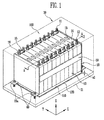
FIG. 1 illustrates a perspective view of a battery module according to an embodiment. -
FIG. 2 illustrates an exploded perspective view of the battery module inFIG. 1 . -
FIG. 3 illustrates a sectional view taken along line A-A ofFIG. 1 . -
FIG. 4A illustrates a perspective view of a heat exchange member in a battery module according to another embodiment. -
FIG. 4B illustrates a sectional view taken along line B-B inFIG. 4A . -
FIG. 5 illustrates a perspective view of a battery module according to still another embodiment. -
FIG. 6 illustrates an exploded perspective view of the battery module inFIG. 5 . -
FIG. 7 illustrates a sectional view taken along line C-C inFIG. 5 . - Referring to
FIGS. 1 and2 , thebattery module 100 according to this embodiment may include a plurality ofbattery cells 10 aligned in one direction, fixingmembers battery cells 10, i.e. to hold them together, aheat exchange member 110 provided adjacent to abottom surface 17 of the plurality ofbattery cells 10, and one or moreelastic members 120, for example an elastic sheet, provided beneath theheat exchange member 110. Theelastic member 120 may be provided on asupport portion 31. In this case, thefixing member 18 may be fastened to thesupport portion 31. Afirst fastening portion 18a may be provided to thefixing member 18, and asecond fastening portion 32 fastened to thefirst fastening portion 18a may be provided to the support portion (eg. support plate) 31 supporting thebattery module 100. For example, the first fastening portion is alug 18a extending from afixing plate 18, the lug having a through hole for receiving a screw orbolt 40 that screws into acorresponding hole 32 in thesupport plate 31. - Each
battery cell 10 is, for example, a prismatic cell, the wide flat surfaces of the cells being stacked together to form the battery module. - Each
battery cell 10 may include a battery case, and an electrode assembly and an electrolyte, which are accommodated in the battery case. The electrode assembly and the electrolyte generate electrochemical energy through a reaction therebetween, and the battery case is hermetically sealed by acap assembly 14. Thecap assembly 14 may be provided with positive andnegative electrode terminals vent 13. Thevent 13 is a safety means of thebattery cell 10, which acts as a passage through which gas generated in thebattery cell 10 is exhausted to the outside of thebattery cell 10. The positive andnegative electrode terminals battery cells 10 are electrically connected through a bus-bar 15, and the bus-bar 15 may be fixed by anut 16 or the like. - The
battery module 100 may be used as one power source by binding the plurality ofbattery cells 10 as one bundle, using thefixing members fixing members end plates 18 provided to face wide surfaces of thebattery cells 10 at the outside of thebattery cells 10, and aconnection plate 19 configured to connect the pair ofend plates 18 to each other. - Generally, a battery module includes a plurality of battery cells, and the battery cells generate a large amount of heat while being charged/discharged. The generated heat is accumulated in the battery cells, thereby accelerating the degradation of the battery cells. For example, the accumulated heat may reduce stability, e.g., cause an explosion. In particular, in a conventional battery module with high power, a cooling device may be provided to reduce accumulated heat. However, it may be difficult to control a plurality of battery cells without any difference in temperature between the battery cells, and therefore, the reliability of the conventional battery module may be lowered.
- In the battery module according to example embodiments, all the battery cells may be equally cooled down without any difference in temperature between the battery cells in the battery module, using a new structure. Further, no additional processes are added in the manufacturing of the battery module with the new structure applied to the battery module, thereby improving the productivity of the battery module. When the battery module is mounted, an assembling tolerance for the battery module is provided, thereby reducing a failure rate in the manufacturing of the battery module.
-
FIG. 3 illustrates a sectional view taken along line A-A ofFIG. 1 . Referring toFIG. 3 , the pair ofend plates 18 are provided opposite to each other, and the plurality ofbattery cells 10 are aligned in one direction between theend plates 18 so that wide surfaces of neighbouringbattery cells 10 are opposite to each other. The pair ofend plates 18 press thebattery cells 10 toward the inside of thebattery cells 10, and theconnection plate 19 fixes side surfaces of thebattery cells 10 while connecting the pair ofend plates 18 to each other (FIGS. 1-2 ). Thefirst fastening portion 18a may be provided to eachend plate 18. Thefastening portion 18a may be bent away from, i.e., in a direction opposite to that of, thebattery cells 10 at a lower end of eachend plate 18. For example, eachend plate 18 may be arranged with acorresponding fastening portion 18a in a L-shape, so thefastening portion 18a may extend in parallel to the surface of thesupport plate 31. Accordingly, when thefastening portions 18a on both sides of thebattery module 100 are fastened to thesupport plate 31 bybolts 40, theentire battery module 100 may be pulled closer to the surface of thesupport plate 31. In this case, it is sufficient that thefirst fastening portion 18a is fastened to the support plate while overlapping with the support plate. Therefore, thefirst fastening portion 18a may be any portion of the fixingmembers - In the
battery module 100 according to this embodiment, the support portion is a portion on which thebattery module 100 is mounted. For example, as illustrated inFIGS. 1-2 , the support portion may include a plate comprising onepart 31 of ahousing 30. Thefirst fastening portion 18a may be provided to overlap with thesupport plate 31 of thehousing 30, and thesecond fastening portion 32 may be provided at a position corresponding to that of thefirst fastening portion 18a in thesupport plate 31. The first andsecond fastening portions separate fastening member 40, so as to fix thebattery module 100. For example, thefastening member 40 may include a bolt, stud or the like. - The
battery module 100 further includes theheat exchange member 110 and theelastic member 120, which are provided adjacent to thebottom surface 17 of thebattery cells 10 so as to cool down thebattery cells 10. Theelastic member 120 may be interposed between thesupport plate 31 and theheat exchange member 110. - The
heat exchange member 110 may include a cooling plate provided to have a size corresponding to that of thebottom surface 17 of the plurality ofbattery cells 10, e.g., the cooling plate may completely overlap (ie. be coextensive with) the entire bottom surfaces of all thebattery cells 10 in thebattery module 100. That is, the cooling plate may include a passage through which a cooled heat exchange medium can move. The heat exchange medium performs a heat exchange with thebattery cells 10 while circulating inside theheat exchange member 110, i.e., inside the cooling plate. - The
elastic member 120 may be provided to correspond to thebottom surface 17 of the plurality ofbattery cells 10, e.g., theelastic member 120 may completely overlap theentire bottom surface 17. For example, theelastic member 120 has a constant pressure load, and may be made of rubber and/or sponge and/or other elastic materials. That is, theelastic member 120 may be pressed to a predetermined thickness by the weight of the plurality ofbattery cells 10. In this case, the thickness a2(seeFIG. 2 ) of theelastic member 120 before being pressed by thebattery cells 10 is thicker than the thickness a1(seeFIG. 1 ) of theelastic member 120 after being pressed by thebattery cells 10. - That is, the
elastic member 120 having a predetermined pressure load is provided on thesupport plate 31 of thehousing 30, and theheat exchange member 110 is then positioned on theelastic member 120, e.g., theelastic member 120 may be positioned directly between thesupport plate 31 and theheat exchange member 110. Subsequently, the plurality ofbattery cells 10 are mounted on theheat exchange member 110, and thefirst fastening portion 18a of eachend plate 18 is fastened to thesecond fastening portion 32 in thesupport plate 31 of thehousing 30. In this case, the first andsecond fastening portions battery cells 10 compress theelastic member 120. Thus, theheat exchange member 110 and thebattery cells 10 are tightly pressed against each other, by the restoring force of theelastic member 120, thereby improving the heat exchange efficiency of thebattery cells 10. Further, theelastic member 120 may provide an assembling tolerance when thebattery cells 10 are fixed on the onesurface 31 of thehousing 30, thereby improving the productivity of thebattery module 100. - Hereinafter, other embodiments will be described with reference to
FIGS. 4A to 7 . Contents of these embodiments, except the following contents, are similar to those of the embodiment described with reference toFIGS. 1 to 3 , and therefore, their detailed descriptions will be omitted. -
FIG. 4A illustrates a perspective view of a heat exchange member in a battery module according to another embodiment.FIG. 4B illustrates a sectional view taken along line B-B of the heat exchange member inFIG. 4A . - Referring to
FIGS. 4A and4B , a battery module according to an embodiment may have anelastic member 220 provided beneath the heat exchange member. Theelastic member 220 may be pressed to a predetermined thickness with respect to the pressure applied by thebattery cells 10. For example, asurface 221 of theelastic member 220 may be formed in an embossed pattern. That is, a plurality of protrudingportions 222 may be provided on thesurface 221 of theelastic member 220. In this case, the protrudingportions 222 may be provided on one surface or bothsurfaces 221 of theelastic member 220. The plurality of protrudingportions 222 may be formed in an embossed pattern, so that thebattery cells 10 can effectively press theelastic member 220. Further, the shape of the protrudingportions 222 may be appropriately changed, according to the shape of a bottom surface of thebattery cells 10, so that it is possible to easily cope with a change in design of the battery module. -
FIG. 5 illustrates a perspective view of a battery module according to still another embodiment.FIG. 6 illustrates an exploded perspective view of the battery module ofFIG. 5 .FIG. 7 illustrates a sectional view taken along line C-C inFIG. 5 . - Referring to
FIGS. 5 to 7 , abattery module 300 according to this embodiment may include the plurality ofbattery cells 10 aligned in one direction, and the pair ofend plates 18 and theconnection plate 19, configured to fix the plurality ofbattery cells 10, and aheat exchange member 310 configured to perform a heat exchange with thebattery cells 10 while coming in contact with thebottom surface 17 of thebattery cells 10. Thefirst fastening portion 18a may be provided to eachend plate 18, and asecond fastening portion 332 fastened to thefirst fastening portion 18a may be provided to a support portion. Anelastic member 320 may be provided beneath theheat exchange member 310. - In the
battery module 300 according to this embodiment, the support portion may include aseparate frame 330 provided between thesupport plate 31 and theelastic member 320. Theelastic member 320 is provided on theframe 330, and thefirst fastening portion 18a of eachend plate 18 may be fastened to thesecond fastening portion 332 provided in theframe 330. That is, thebattery module 300 is accommodated in thehousing 30, so as to be supported by theseparate frame 330 provided on thesupport portion 31 of thehousing 30. - An
accommodating portion 333 having theheat exchange member 310 provided therein may be formed inside theframe 330. In this case, theaccommodating portion 333 of theframe 330 includes a recess provided to correspond to the shape of theheat exchange member 310. The second fastening portion 322 fastened to thefirst fastening portion 18a may be provided in theframe 330. For example, the battery module is provided in theaccommodating portion 333. In this case, thefirst fastening portion 18a may be provided to overlap with thesecond fastening portion 332 provided at an edge of theaccommodating portion 333. - The
elastic member 320 is provided in theaccommodating portion 333, and theheat exchange member 310 and thebattery cells 10 are sequentially provided on theelastic member 320, so that theelastic member 320 can receive a constant pressure load applied by thebattery cells 10. Theframe 330 is used as the support portion supporting the plurality ofbattery cells 10, so that it is possible to facilitate the movement of thebattery module 300. Thus, the examination of thebattery module 300 can be performed without separating thebattery module 300 from thehousing 30, so that thebattery module 300 can be efficiently used for a long period of time. - Example embodiments have been disclosed herein, and although specific terms are employed, they are used and are to be interpreted in a generic and descriptive sense only and not for purpose of limitation. In some instances, as would be apparent to one of ordinary skill in the art as of the filing of the present application, features, characteristics, and/or elements described in connection with a particular embodiment may be used singly or in combination with features, characteristics, and/or elements described in connection with other embodiments unless otherwise specifically indicated. Accordingly, it will be understood by those of skill in the art that various changes in form and details may be made without departing from the scope of the invention as set forth in the following claims.
Claims (15)
- A battery module, comprising:a plurality of battery cells (10);a fixing member (18, 19) configured to hold the plurality of battery cells together;a heat exchange member (110, 310) adjacent to bottom surfaces (17) of the plurality of battery cells; andat least one elastic member (120, 220, 320) under the heat exchange member, the at least one elastic member being on a support portion (31, 330), and the fixing member (18) being fastened to the support portion (31, 330).
- The battery module as claimed in claim 1, wherein the fixing member includes a first fastening portion (18a), the first fastening portion being fastened to a second fastening portion (32, 332) in the support portion.
- The battery module as claimed in claim 2, wherein the fixing member further comprises:a pair of end plates (18) outside the battery cells, the pair of end plates defining two outermost edges of the battery module and facing wide surfaces of the battery cells; anda connection plate (19) configured to connect the pair of end plates to each other, a first fastening portion being formed at each of the pair of end plates.
- The battery module as claimed in claim 2 or 3, wherein the first fastening portion comprises a lug at a lower end of each of the pair of end plates.
- The battery module as claimed in claim 2, 3 or 4, wherein the support portion includes one side of a housing, the housing being configured to accommodate the plurality of battery cells therein.
- The battery module as claimed in claim 5, wherein the support portion includes a separate frame (330) between the side of the housing and the elastic member.
- The battery module as claimed in claim 6, wherein the second fastening portion (332) is in the frame.
- The battery module as claimed in claim 6 or 7, further comprising an accommodating portion (333) inside the frame, the heat exchange member (310) being positioned in the accommodating portion.
- The battery module as claimed in claim 8, wherein the accommodating portion of the frame comprises a recess corresponding to the shape of the heat exchange member.
- The battery module as claimed in claim 8 or 9, wherein the first fastening portion overlaps the second fastening portion, the second fastening portion being at an edge of the accommodating portion.
- The battery module as claimed in any one of the preceding claims, wherein the heat exchange member includes a cooling plate that is coextensive with the area of the bottom surfaces of the plurality of battery cells.
- The battery module as claimed in any one of the preceding claims, wherein the elastic member comprises an elastic sheet that is coextensive with the area of the bottom surfaces of the plurality of battery cells.
- The battery module as claimed in any one of the preceding claims, wherein the elastic member includes at least one of rubber and sponge.
- The battery module as claimed in any one of the preceding claims, wherein the elastic member has an embossed surface.
- The battery module according to claim 14, wherein the embossed surface comprises a plurality of protrusions that are arranged to press the bottom surfaces of corresponding ones of the battery cells.
Applications Claiming Priority (1)
| Application Number | Priority Date | Filing Date | Title |
|---|---|---|---|
| KR1020130061186A KR101814735B1 (en) | 2013-05-29 | 2013-05-29 | Battery module |
Publications (1)
| Publication Number | Publication Date |
|---|---|
| EP2808922A1 true EP2808922A1 (en) | 2014-12-03 |
Family
ID=50819645
Family Applications (1)
| Application Number | Title | Priority Date | Filing Date |
|---|---|---|---|
| EP20140170320 Withdrawn EP2808922A1 (en) | 2013-05-29 | 2014-05-28 | Battery module |
Country Status (4)
| Country | Link |
|---|---|
| US (1) | US20140356684A1 (en) |
| EP (1) | EP2808922A1 (en) |
| KR (1) | KR101814735B1 (en) |
| CN (1) | CN104218271A (en) |
Cited By (1)
| Publication number | Priority date | Publication date | Assignee | Title |
|---|---|---|---|---|
| EP3264494A1 (en) * | 2016-06-28 | 2018-01-03 | MAN Truck & Bus AG | Battery module for a vehicle, in particular a commercial vehicle |
Families Citing this family (22)
| Publication number | Priority date | Publication date | Assignee | Title |
|---|---|---|---|---|
| JP5603504B2 (en) * | 2011-10-28 | 2014-10-08 | 川崎重工業株式会社 | Straddle-type electric vehicle |
| WO2015178456A1 (en) * | 2014-05-22 | 2015-11-26 | 株式会社東芝 | Battery pack and battery device |
| KR101661972B1 (en) * | 2015-02-17 | 2016-10-04 | 엘지전자 주식회사 | Battery Pack for Elecetronic Vehicles |
| KR102026386B1 (en) * | 2015-06-03 | 2019-09-27 | 주식회사 엘지화학 | Battery module |
| US10312485B2 (en) * | 2015-07-23 | 2019-06-04 | Ford Global Technologies, Llc | Battery assembly array plate |
| KR102072765B1 (en) | 2016-02-22 | 2020-03-02 | 주식회사 엘지화학 | Battery module, battery pack comprising the battery module and vehicle comprising the battery pack |
| SG10202010362RA (en) * | 2016-04-20 | 2020-11-27 | Corvus Energy Inc | Battery cell carrier and enclosure for stack assembly comprising multiple battery cell carriers |
| CN107394063B (en) * | 2016-05-16 | 2023-06-06 | 宁德时代新能源科技股份有限公司 | Secondary battery |
| KR102051108B1 (en) * | 2016-06-13 | 2019-12-02 | 주식회사 엘지화학 | Battery module, battery pack comprising the battery module and vehicle comprising the battery pack |
| CN105957990A (en) * | 2016-07-01 | 2016-09-21 | 奇瑞汽车股份有限公司 | Automobile power battery pack frame |
| FR3054308B1 (en) * | 2016-07-25 | 2020-02-07 | Valeo Systemes Thermiques | COOLING ASSEMBLY OF AN ELECTRICAL ENERGY STORAGE DEVICE. |
| DE102016009212A1 (en) | 2016-08-01 | 2018-02-01 | Audi Ag | Battery module and battery |
| KR101971536B1 (en) * | 2016-09-28 | 2019-08-13 | 주식회사 엘지화학 | Secondary battery module improved in frame structure and frame assembly for the same |
| JP6310990B1 (en) * | 2016-10-26 | 2018-04-11 | 本田技研工業株式会社 | Battery module fixing structure |
| JP7027255B2 (en) * | 2018-05-31 | 2022-03-01 | 本田技研工業株式会社 | Battery pack |
| KR102373774B1 (en) | 2018-08-21 | 2022-03-14 | 에스케이온 주식회사 | Battery Module and Battery Pack including the same |
| KR102157799B1 (en) * | 2018-09-19 | 2020-09-18 | 이용진 | Battery assembly for electoronic cigarette equipped with separable PCB |
| DE102019201077A1 (en) * | 2019-01-29 | 2020-07-30 | Audi Ag | Battery assembly method for providing a battery assembly and assembly |
| DE102019202156A1 (en) * | 2019-02-18 | 2020-08-20 | Audi Ag | Fastening arrangement, tolerance compensation arrangement for a fastening device and assembly method for fastening a battery module to a cooling device |
| KR102483911B1 (en) * | 2021-02-25 | 2023-01-02 | 고등기술연구원연구조합 | Battery case for vehicle |
| US20230083678A1 (en) * | 2021-09-16 | 2023-03-16 | Lunar Energy, Inc. | Modular battery system |
| CN216133942U (en) * | 2021-11-08 | 2022-03-25 | 宁德时代新能源科技股份有限公司 | Backplate, battery pack and consumer at bottom of battery |
Citations (2)
| Publication number | Priority date | Publication date | Assignee | Title |
|---|---|---|---|---|
| DE102011003535A1 (en) * | 2011-02-02 | 2012-08-02 | Behr Gmbh & Co. Kg | tensioning devices |
| EP2492990A1 (en) * | 2011-02-23 | 2012-08-29 | SB LiMotive Co., Ltd. | Means for mounting a battery module |
Family Cites Families (3)
| Publication number | Priority date | Publication date | Assignee | Title |
|---|---|---|---|---|
| KR101047937B1 (en) * | 2009-05-11 | 2011-07-11 | 주식회사 엘지화학 | Battery cartridge including an elastic pressing member, and a battery module comprising the same |
| JP5450128B2 (en) * | 2010-01-28 | 2014-03-26 | 三洋電機株式会社 | Power supply device and vehicle equipped with the same |
| JP2011171029A (en) * | 2010-02-17 | 2011-09-01 | Sanyo Electric Co Ltd | Battery module |
-
2013
- 2013-05-29 KR KR1020130061186A patent/KR101814735B1/en active IP Right Grant
-
2014
- 2014-03-07 US US14/200,255 patent/US20140356684A1/en not_active Abandoned
- 2014-05-28 EP EP20140170320 patent/EP2808922A1/en not_active Withdrawn
- 2014-05-29 CN CN201410234026.2A patent/CN104218271A/en active Pending
Patent Citations (2)
| Publication number | Priority date | Publication date | Assignee | Title |
|---|---|---|---|---|
| DE102011003535A1 (en) * | 2011-02-02 | 2012-08-02 | Behr Gmbh & Co. Kg | tensioning devices |
| EP2492990A1 (en) * | 2011-02-23 | 2012-08-29 | SB LiMotive Co., Ltd. | Means for mounting a battery module |
Cited By (1)
| Publication number | Priority date | Publication date | Assignee | Title |
|---|---|---|---|---|
| EP3264494A1 (en) * | 2016-06-28 | 2018-01-03 | MAN Truck & Bus AG | Battery module for a vehicle, in particular a commercial vehicle |
Also Published As
| Publication number | Publication date |
|---|---|
| KR101814735B1 (en) | 2018-01-03 |
| US20140356684A1 (en) | 2014-12-04 |
| KR20140140679A (en) | 2014-12-10 |
| CN104218271A (en) | 2014-12-17 |
Similar Documents
| Publication | Publication Date | Title |
|---|---|---|
| EP2808922A1 (en) | Battery module | |
| EP3282515B1 (en) | Battery module, battery pack comprising battery module, and vehicle comprising battery pack | |
| EP2808921B1 (en) | Battery module | |
| US9859544B2 (en) | Battery module | |
| US9203065B2 (en) | Battery module | |
| EP2521204B1 (en) | Battery module | |
| US9660230B2 (en) | Battery pack having end plates | |
| JP6148202B2 (en) | Storage device cooling structure | |
| EP2631965B1 (en) | Battery module | |
| US9166260B2 (en) | Battery module | |
| EP2357689A1 (en) | Battery module | |
| US11652233B2 (en) | Battery pack | |
| JP6184959B2 (en) | Battery system, vehicle including battery system, and power storage device | |
| US20140220396A1 (en) | Battery pack | |
| KR101799565B1 (en) | Battery Pack of Improved Safety | |
| KR20130105596A (en) | Power storage module | |
| US9012063B2 (en) | Battery module | |
| EP3255703B1 (en) | Battery pack | |
| US20150064523A1 (en) | Battery module | |
| EP2490277B1 (en) | Battery Module | |
| KR20140123693A (en) | Battery Pack | |
| KR102028916B1 (en) | Battery Pack for Secondary Battery | |
| KR102545071B1 (en) | Leaf spring for pressurizing cell and electric energy storage pack having the same | |
| KR101357593B1 (en) | Battery pack |
Legal Events
| Date | Code | Title | Description |
|---|---|---|---|
| PUAI | Public reference made under article 153(3) epc to a published international application that has entered the european phase |
Free format text: ORIGINAL CODE: 0009012 |
|
| 17P | Request for examination filed |
Effective date: 20140528 |
|
| AK | Designated contracting states |
Kind code of ref document: A1 Designated state(s): AL AT BE BG CH CY CZ DE DK EE ES FI FR GB GR HR HU IE IS IT LI LT LU LV MC MK MT NL NO PL PT RO RS SE SI SK SM TR |
|
| AX | Request for extension of the european patent |
Extension state: BA ME |
|
| R17P | Request for examination filed (corrected) |
Effective date: 20150603 |
|
| RBV | Designated contracting states (corrected) |
Designated state(s): AL AT BE BG CH CY CZ DE DK EE ES FI FR GB GR HR HU IE IS IT LI LT LU LV MC MK MT NL NO PL PT RO RS SE SI SK SM TR |
|
| STAA | Information on the status of an ep patent application or granted ep patent |
Free format text: STATUS: THE APPLICATION HAS BEEN WITHDRAWN |
|
| 18W | Application withdrawn |
Effective date: 20160429 |