EP3255441A1 - Electric current sensor - Google Patents
Electric current sensor Download PDFInfo
- Publication number
- EP3255441A1 EP3255441A1 EP16746469.2A EP16746469A EP3255441A1 EP 3255441 A1 EP3255441 A1 EP 3255441A1 EP 16746469 A EP16746469 A EP 16746469A EP 3255441 A1 EP3255441 A1 EP 3255441A1
- Authority
- EP
- European Patent Office
- Prior art keywords
- current
- current sensor
- calibration
- alternating current
- alternating
- Prior art date
- Legal status (The legal status is an assumption and is not a legal conclusion. Google has not performed a legal analysis and makes no representation as to the accuracy of the status listed.)
- Withdrawn
Links
Images





Classifications
-
- G—PHYSICS
- G01—MEASURING; TESTING
- G01R—MEASURING ELECTRIC VARIABLES; MEASURING MAGNETIC VARIABLES
- G01R15/00—Details of measuring arrangements of the types provided for in groups G01R17/00 - G01R29/00, G01R33/00 - G01R33/26 or G01R35/00
- G01R15/14—Adaptations providing voltage or current isolation, e.g. for high-voltage or high-current networks
- G01R15/20—Adaptations providing voltage or current isolation, e.g. for high-voltage or high-current networks using galvano-magnetic devices, e.g. Hall-effect devices, i.e. measuring a magnetic field via the interaction between a current and a magnetic field, e.g. magneto resistive or Hall effect devices
- G01R15/202—Adaptations providing voltage or current isolation, e.g. for high-voltage or high-current networks using galvano-magnetic devices, e.g. Hall-effect devices, i.e. measuring a magnetic field via the interaction between a current and a magnetic field, e.g. magneto resistive or Hall effect devices using Hall-effect devices
-
- G—PHYSICS
- G01—MEASURING; TESTING
- G01R—MEASURING ELECTRIC VARIABLES; MEASURING MAGNETIC VARIABLES
- G01R15/00—Details of measuring arrangements of the types provided for in groups G01R17/00 - G01R29/00, G01R33/00 - G01R33/26 or G01R35/00
- G01R15/14—Adaptations providing voltage or current isolation, e.g. for high-voltage or high-current networks
- G01R15/20—Adaptations providing voltage or current isolation, e.g. for high-voltage or high-current networks using galvano-magnetic devices, e.g. Hall-effect devices, i.e. measuring a magnetic field via the interaction between a current and a magnetic field, e.g. magneto resistive or Hall effect devices
-
- G—PHYSICS
- G01—MEASURING; TESTING
- G01R—MEASURING ELECTRIC VARIABLES; MEASURING MAGNETIC VARIABLES
- G01R19/00—Arrangements for measuring currents or voltages or for indicating presence or sign thereof
- G01R19/0092—Measuring current only
-
- G—PHYSICS
- G01—MEASURING; TESTING
- G01R—MEASURING ELECTRIC VARIABLES; MEASURING MAGNETIC VARIABLES
- G01R35/00—Testing or calibrating of apparatus covered by the other groups of this subclass
- G01R35/005—Calibrating; Standards or reference devices, e.g. voltage or resistance standards, "golden" references
Definitions
- the present invention relates to a current sensor.
- a current sensor includes setting data that associates the magnitude of current with detection signals in a predetermined correspondence relationship.
- the current sensor outputs a detection signal corresponding to the magnitude of detected current based on the setting data.
- the current sensor cannot continuously output a predetermined detection signal corresponding to the magnitude of detected current due to various causes such as an environmental change.
- the current sensor is calibrated to correct the setting data.
- the calibration is generally performed by letting the current sensor detect direct current as described in PTL 1.
- the current sensor may detect alternating current, not direct current.
- alternating current when the alternating current is detected with use of setting data corrected based on calibration using direct current, there is a problem in which an error is generated between a current value derived from a detection signal and a true value of the alternating current.
- a current sensor includes: a current detection unit that detects alternating current flowing in a conductor; and a storage unit that stores correction data based on a detection value of predetermined calibration alternating current flowing in the conductor, the detection value being detected by the current detection unit.
- an error generated between a current value derived from a detection signal and a true value of the alternating current can be reduced.
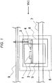
- FIGS. 1 and 2 illustrate an example in which a current sensor 8 according to the present embodiment has been implemented in an inverter device.
- FIG. 2 is a view taken along the arrow YA1 of FIG. 1 .
- a bus bar 7 is made of a conductor such as copper.
- the bus bar 7 is a part of a main circuit of the inverter. Current output from a power module or the like flows in the bus bar 7. When the current flows in the bus bar 7, magnetic flux is generated, centering on the bus bar 7.
- the current sensor 8 detects the magnetic flux generated by the current flowing in the bus bar 7 and outputs a detection signal to an inverter circuit board 9.
- the inverter circuit board 9 is a control board of the inverter and performs feedback control with use of the detection signal received from the current sensor 8.
- the current sensor 8 includes a current sensor circuit 1, a current sensor board 2, a communication terminal 3, a peripheral electronic component 4, a magnetic shield 5, and a structure mold 6.
- the communication terminal 3 is a terminal that electrically connects the current sensor circuit 1 to the inverter circuit board 9.
- the communication terminal 3 transmits a signal of the current sensor circuit 1 to the inverter circuit board 9.
- the communication terminal 3 also transmits a signal from the inverter circuit board 9 to the current sensor circuit 1. Details of transmission of the signal from the inverter circuit board 9 to the current sensor circuit 1 will be described below.
- the communication terminal 3 further transmits electric power for use in operation of the current sensor circuit 1.
- the current sensor circuit 1 detects the magnetic flux generated by the current flowing in the bus bar 7 and outputs a detection signal to the inverter circuit board 9 via the communication terminal 3. Details of the current sensor circuit 1 will be described below.
- the peripheral electronic component 4 is a peripheral RC chip component mounted on the current sensor board 2.
- the current sensor board 2 is a board on which the current sensor circuit 1, the communication terminal 3, and the peripheral electronic component 4 are mounted.
- the current sensor board 2 is fixed to the bus bar 7 via the structure mold 6 so that the current sensor circuit 1 may be located away from the bus bar 7 as much as a predetermined distance.
- the magnetic shield 5 is provided to decrease an influence of a magnetic noise. As illustrated in FIG. 2 , the magnetic shield 5 is formed in a rectangular U shape to surround the bus bar 7 and the current sensor board 2.
- the structure mold 6 is a structure mold that structurally holds the current sensor board 2, the magnetic shield 5, and a part of the bus bar 7.
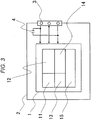
- FIG. 3 illustrates the current sensor circuit 1 and peripheral components thereof.
- the current sensor circuit 1 includes a magnetic flux detection unit 11, a signal adjustment unit 12, a control unit 13, a communication unit 14, and a memory 15.
- the control unit 13 controls operations of the respective other components of the current sensor circuit 1.
- the memory 15 is a data-rewritable memory such as an EEPROM.
- the memory 15 stores setting data including offset data and output gain data.
- the setting data stored in the memory 15 is output to the signal adjustment unit 12 by the control unit 13 as needed. Also, at the time of below-mentioned calibration of the setting data, the setting data stored in the memory 15 is corrected by the control unit 13.
- the magnetic flux detection unit 11 detects current flowing in the bus bar 7. Specifically, the magnetic flux detection unit 11 includes a hall element and detects magnetic flux generated by the current flowing in the bus bar 7 by means of the hall element to detect the current flowing in the bus bar 7. The magnetic flux detection unit 11 then outputs a voltage signal corresponding to the magnitude of the detected current to the signal adjustment unit 12.
- the signal adjustment unit 12 generates a detection signal based on the resultant current detected by the magnetic flux detection unit 11 and the setting data stored in the memory 15. Specifically, the signal adjustment unit 12 generates the detection signal by doing offset adjustment and gain adjustment of the voltage signal received from the magnetic flux detection unit 11 based on the setting data stored in the memory 15 and output from the control unit 13.
- the signal adjustment unit 12 is designed to erase stored setting data each time the electric power supply is stopped. Thus, the signal adjustment unit 12 receives setting data from the control unit 13 each time the current sensor circuit 1 is activated.
- the communication unit 14 outputs the detection signal obtained from the signal adjustment unit 12 to the inverter circuit board 9 (refer to FIG. 1 ) via the communication terminal 3.
- the communication unit 14 also receives correction data for correcting the setting data from an outside via the communication terminal 3 at the time of the calibration of the setting data stored in the memory 15. That is, the communication terminal 3 is used when the communication unit 14 outputs the detection signal and receives the correction data.
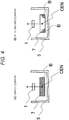
- FIGS. 4(a) and 4(b) illustrates a distribution of magnetic flux density B generated in the bus bar 7 when current flows in the bus bar 7.
- FIG. 4(a) illustrates a case in which direct current flows while FIG. 4(b) illustrates a case in which alternating current flows.
- the current density in the bus bar 7 is distributed uniformly.
- the magnetic flux density B is also distributed uniformly as illustrated in FIG. 4(a) .
- the magnetic flux density B is also concentrated on the corners of the bus bar 7 as illustrated in FIG. 4(b) .
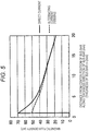
- FIG. 5 illustrates a result of current flow under each of the conditions illustrated in FIGS. 4(a) and 4(b) and illustrates magnetic flux density against a distance from a center position CEN of the bus bar 7 illustrated in each of FIGS. 4(a) and 4(b) along a thickness direction of the bus bar 7 (refer to FIGS. 4(a) and 4(b) ).
- the solid-line graph in FIG. 5 represents the result of direct current illustrated in FIG. 4(a) .
- the dashed-line graph in FIG. 5 represents the result of alternating current (frequency: 10000 Hz) illustrated in FIG. 4(b) .
- FIG. 5 illustrates a result of current flow under each of the conditions illustrated in FIGS. 4(a) and 4(b) and illustrates magnetic flux density against a distance from a center position CEN of the bus bar 7 illustrated in each of FIGS. 4(a) and 4(b) along a thickness direction of the bus bar 7 (refer to FIGS. 4(a) and 4
- a larger difference occurs in the magnetic flux density between the alternating current and the direct current at a closer position to the center position CEN.
- a detection value of the alternating current differs from a detection value of the direct current as much as the magnetic flux density of 3 mT or so. Since such a difference is generated, it is not preferable to perform calibration using direct current and then detect alternating current. That is, in a case in which alternating current is to be detected, calibration for this needs to be performed using alternating current.
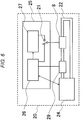
- FIG. 6 illustrates calibration according to the present embodiment.
- a calibration device 20 has a configuration from which the current sensor 8 (product sensor) to be calibrated is at least eliminated. That is, the calibration device 20 includes a current sensor calibration unit 25, an alternating current generation unit 24, a bus bar 22, and a reference current sensor 29.
- the current sensor calibration unit 25 includes a current sensor output comparison unit 26, a current sensor communication unit 27, and a switch 21.
- the reference current sensor 29 is a reference current sensor that can detect current flowing in the bus bar 22 with high accuracy.
- the bus bar 22 is made of a conductor such as copper.
- the bus bar 22 is connected to the alternating current generation unit 24 at both ends thereof.
- the reference current sensor 29 and the current sensor 8 detect alternating current flowing in the bus bar 22 (below-mentioned calibration alternating current) and output detection signals to the current sensor output comparison unit 26.
- the alternating current generation unit 24 is a single-phase alternating current generation source and mainly includes a not-illustrated voltage adjustment unit and a not-illustrated transformer.
- the alternating current generation unit 24 communicates with the current sensor output comparison unit 26 to receive an instruction from the current sensor output comparison unit 26 and output alternating current to the bus bar 22. This alternating current will be referred to as calibration alternating current.
- the current sensor output comparison unit 26 instructs the alternating current generation unit 24 to output the calibration alternating current at the time of below-mentioned output gain adjustment.
- the current sensor output comparison unit 26 compares an output of the reference current sensor 29 with an output of the current sensor 8 and outputs the difference of the output voltage to the current sensor communication unit 27.
- the current sensor communication unit 27 generates the correction data for correcting the setting data stored in the memory 15 of the current sensor 8 based on the aforementioned difference of the output voltage and outputs the correction data to the current sensor 8.
- the current sensor 8 corrects the setting data stored in the memory 15 with use of the correction data.
- the switch 21 switches between the current sensor output comparison unit 26 and the current sensor communication unit 27 as a destination of the current sensor 8.
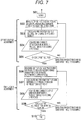
- FIG. 7 is a flowchart of calibration according to the present embodiment.
- the flowchart includes an offset voltage adjustment process consisting of steps S02 to S05 and an output gain adjustment process consisting of steps S06 to S09.
- the product sensor in FIG. 7 refers to the current sensor 8
- the reference sensor refers to the reference current sensor 29.
- a procedure of the calibration according to the present embodiment will be described with reference to FIG. 7 .
- step S01 When the calibration flow is started (step S01), the procedure moves to step S02. In step S02, no current flows in the bus bar 22. In this state, the current sensor output comparison unit 26 measures respective offset voltage of the current sensor 8 and the reference current sensor 29. After step S02, the procedure moves to step S03.
- step S03 the current sensor output comparison unit 26 subtracts the offset voltage of the reference current sensor 29 from the offset voltage of the current sensor 8 to calculate an offset voltage error.
- the current sensor output comparison unit 26 transmits offset correction data including the offset voltage error to the current sensor communication unit 27.
- step S04 the current sensor communication unit 27 outputs the aforementioned offset correction data to the current sensor 8.
- the control unit 13 corrects the offset data of the setting data stored in the memory 15 with use of the aforementioned offset correction data. Specifically, the control unit 13 adds the offset voltage error to the offset data of the setting data.
- step S05 the procedure moves to step S05.
- step S05 the current sensor output comparison unit 26 measures respective offset voltage of the current sensor 8 and the reference current sensor 29 in a state of no electric conduction to the bus bar 22 in a similar manner to step S02.
- the current sensor output comparison unit 26 then checks if the voltage value of the offset voltage of the current sensor 8 falls within a targeted output range. That is, the current sensor output comparison unit 26 determines if the difference derived by subtracting the offset voltage of the reference current sensor 29 from the offset voltage of the current sensor 8 is equal to or less than a predetermined value. In a case of affirmative determination, the procedure moves to step S06. In a case of negative determination, the procedure moves to step S02, and the similar procedure follows. In a case in which the negative determination is given a predetermined number of times, such as five times, in step S05, the current sensor 8 is determined to be a defective product.
- step S06 the alternating current generation unit 24 provides the bus bar 22 with the calibration alternating current in response to an instruction of the current sensor output comparison unit 26.
- the frequency of the calibration alternating current is a frequency for the time when the current sensor 8 is actually used, that is, a frequency of alternating current to be measured. Also, due to a below-mentioned reason (refer to FIG. 9 ), the amplitude of the calibration alternating current is set to amplitude of the maximum current to be provided to the bus bar 22 when the current sensor 8 is actually used.
- the current sensor output comparison unit 26 measures respective output voltage waveforms output from the current sensor 8 and the reference current sensor 29. After step S06, the procedure moves to step S07.
- step S07 the current sensor output comparison unit 26 calculates an output gain error from the voltage waveforms of the current sensor 8 and the reference current sensor 29.
- the current sensor output comparison unit 26 transmits output gain correction data including the output gain error to the current sensor communication unit 27.
- step S07 the procedure moves to step S08.
- step S08 the current sensor communication unit 27 outputs the aforementioned output gain correction data to the current sensor 8.
- the control unit 13 corrects the output gain data of the setting data stored in the memory 15 with use of the aforementioned output gain correction data. Specifically, the control unit 13 adds the output gain error to the output gain data of the setting data.
- step S09 the procedure moves to step S09.
- step S09 the current sensor output comparison unit 26 measures respective output voltage waveforms of the current sensor 8 and the reference current sensor 29 in a state in which the calibration alternating current flows in the bus bar 22 in a similar manner to step S06.
- the current sensor output comparison unit 26 then checks if the voltage amplified by the output gain of the current sensor 8 falls within a targeted output range. That is, the current sensor output comparison unit 26 determines if the difference between the amplitude of the output voltage waveform of the current sensor 8 and the amplitude of the output voltage waveform of the reference current sensor 29 is equal to or less than a predetermined value. In a case of affirmative determination, the procedure moves to step S10 to end the flow.
- step S06 In a case of negative determination, the procedure moves to step S06, and the similar procedure follows .
- the negative determination is given a predetermined number of times, such as five times, in step S09, the current sensor 8 is determined to be a defective product.
- the corrected setting data based on the detection value of the predetermined calibration alternating current detected by the magnetic flux detection unit 11 is stored in the memory 15.
- a detection error can be prevented from being generated when the current sensor 8 detects the alternating current.
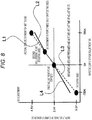
- FIG. 8 illustrates an example of a relationship between input current and output voltage of the current sensor 8 at the time of calibration using direct current.
- the current needs to be provided until the measurement is completed in a state in which the current is stable.
- calibration using a maximum current value 700 A in FIG. 8
- calibration along a dashed line L1 is supposed to be performed, calibration along a solid line L2 may actually be performed.
- FIG. 9 illustrates an example of a relationship between input current and output voltage of the current sensor 8 at the time of calibration according to the present embodiment.
- calibration is performed using alternating current having the maximum amplitude of 700A, which may actually be used.
- the frequency of the alternating current is set to a frequency that is to be used actually.
- calibration can be performed at a current area that is to be used actually, which is a range of from -700 A to +700 A. That is, at the entire current area to be used actually, voltage to be output from the current sensor 8 can have no error.
- the current sensor according to the present embodiment is configured in the following manner and has the following effects.
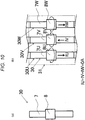
- FIG. 10(a) illustrates a current detection unit 30.
- the current detection unit 30 is a unit in which the current sensor 8 is provided on the bus bar 7 and in which the current sensor 8 detects current flowing in the bus bar 7.
- the current detection unit 30 constitutes a current detection module 31 as illustrated in FIG. 10(b) .
- the current detection module 31 includes as many current detection units 30 as the number of phases of alternating current to be used.
- FIG. 10(b) illustrates the current detection module 31 for three-phase alternating current. Since the current detection module 31 illustrated in FIG. 10(b) is configured to let three-phase alternating current flow, the current detection module 31 includes three current detection units 30. For the following description, reference signs of the three current detection units 30 illustrated in FIG.
- 10(b) will be 30U, 30V, and 30W, respectively.
- reference signs of the bus bars included in the current detection units 30U, 30V, and 30W will be 7U, 7V, and 7W, respectively.
- Reference signs of the current sensors included in the current detection units 30U, 30V, and 30W will be 8U, 8V, and 8W, respectively.
- FIG. 10(b) illustrates a state in which three-phase alternating current flows in the current detection module 31.
- U-phase, V-phase, and W-phase alternating current flows in the bus bars 7U, 7V, and 7W of the current detection units 30U, 30V, and 30W, respectively. That is, phases of alternating current flowing in the respective current detection units 30 differ from each other.
- Solid lines 801a, 801b, and 801c illustrated in FIG. 11 represent voltage waveforms that the current detection module 31 illustrated in FIG. 10(b) outputs.
- the current detection units 30U, 30V, and 30W of the current detection module 31 are supposed to output voltage waveforms represented by dashed lines 802a, 802b, and 802c, respectively.
- the current detection units 30U, 30V, and 30W output the solid lines 801a, 801b, and 801c.
- the current detection module 31 is constituted by three current detection units 30 each of which is calibrated using single-phase alternating current and detects three-phase alternating current, an error as much as a difference between the solid line and the dashed line will be generated. Under such circumstances, in the present embodiment, calibration is performed using three-phase alternating current with use of three current sensors 8.
- FIG. 12 illustrates calibration according to the present embodiment. Calibration according to the present embodiment will be described with reference to FIG. 12 . Description of similar components to those in the first embodiment will be omitted.
- calibration is performed using three-phase alternating current. This is a main difference from the calibration according to the first embodiment ( FIG. 6 ) .
- a calibration device 120 has a configuration from which the current sensors 8U, 8V, and 8W (product sensors) to be calibrated are at least eliminated. That is, the calibration device 120 includes a current sensor calibration unit 125, an alternating current generation unit 124, a bus bar 122, and reference current sensors 129U, 129V, and 129W. Meanwhile, the current sensor calibration unit 125 includes a current sensor output comparison unit, a current sensor communication unit, and a switch fitted to three-phase alternating current detection although these are not illustrated.
- the bus bar 122 includes bus bars 122U, 122V, and 122W. Respective first ends of the bus bars 122U, 122V, and 122W are connected to each other at a point 122P while respective second ends thereof are connected to the alternating current generation unit 124.
- the bus bars 122U, 122V, and 122W are provided with the reference current sensors 129U, 129V, and 129W and the current sensors 8U, 8V, and 8W to be calibrated, respectively.
- the alternating current generation unit 124 outputs three-phase alternating current in response to an instruction of the current sensor calibration unit 125.
- the current sensor according to the present embodiment is configured in the following manner and has the following effects in addition to the effects according to the first embodiment.
- the magnetic flux detection unit 11 detects magnetic flux generated by three-phase alternating current flowing in the three bus bars to respectively detect the three-phase alternating current flowing in the three bus bars.
- Calibration alternating current is also three-phase alternating current corresponding to the targets to be measured, and current of the respective phases flows in the three respective bus bars.
- FIG. 13 illustrates a power inversion device 50 (inverter device 50) including the current sensor 8.
- the current sensor 8 is provided in the current detection module 31 for detection of three-phase alternating current as illustrated in FIG. 10 (b) .
- the current detection module 31 is provided in the power inversion device 50 to cause the current sensor 8 to be provided in the power inversion device 50.
- the power inversion device 50 includes the current detection module 31, an inverter circuit 51, a smoothing capacitor 52, an inverter circuit board 59, and terminals P1, P2, P3, P4, P5, P6, and P7.
- Respective first ends of the bus bars 7U, 7V, and 7W of the current detection module 31 on the right side of the figure are connected to the terminals P5, P6, and P7, respectively.
- loads such as three-phase motors are normally connected to the terminals P5, P6, and P7.
- respective second ends of the bus bars 7U, 7V, and 7W of the current detection module 31 on the left side of the figure are connected to output terminals 51U, 51V, and 51W of the inverter circuit 51, respectively.
- the inverter circuit 51 is connected via the smoothing capacitor 52 and the terminal P1 to a not-illustrated high-voltage power source and is supplied from the high-voltage power source with power to be output to an outside via the terminals P5, P6, and P7.
- the inverter circuit 51 includes high-side U-phase switch UH, V-phase switch VH, and W-phase switch WH and low-side U-phase switch UL, V-phase switch VL, and W-phase switch WL. These switches are controlled by a control circuit 53.
- the inverter circuit board 59 includes the control circuit 53 and a switch 54.
- the control circuit 53 is supplied from a not-illustrated low-voltage power source with low-voltage power via the terminal P3.
- the control circuit 53 receives a control communication signal from a not-illustrated control device via the terminal P2 and is operated.
- the control circuit 53 controls the switch 54 as well as the switches UH, VH, WH, UL, VL, and WL included in the inverter circuit 51.
- the switch 54 is controlled so that the switch 54 may be turned off in a case of below-mentioned calibration and may be turned on in the other cases (normal cases).
- the control circuit 53 receives detection signals from the current sensors 8U, 8V, and 8W in normal cases.
- the reason for turning off the switch 54 in the case of calibration is to prevent a signal of the communication terminal 3 from being input in the control circuit 53 to enable the setting data of the current sensor 8 to be corrected (rewritten) normally by a calibration device.
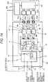
- FIG. 14 illustrates calibration according to the present embodiment.
- the current sensors 8U, 8V, and 8W are calibrated by attaching a calibration device 220 to the power inversion device 50.
- the calibration device 220 includes a current sensor calibration unit 225, an alternating current generation unit 224, bus bars 222U, 222V, and 222W, and reference current sensors 229U, 229V, and 229W.
- the current sensor calibration unit 225 includes a current sensor output comparison unit, a current sensor communication unit, and a switch fitted to three-phase alternating current detection although these are not illustrated.
- the bus bars 222U, 222V, and 222W of the calibration device 220 are connected to the terminals P5, P6, and P7 of the power inversion device 50, respectively.
- Three-phase calibration alternating current generated from the alternating current generation unit 224 is input via the bus bars 222U, 222V, and 222W and the terminals P5, P6, and P7 to the power inversion device 50, respectively.
- the three-phase calibration alternating current flows in the bus bars 7U, 7V, and 7W.
- detection signals output from the current sensors 8U, 8V, and 8W of the power inversion device 50 are input in the current sensor calibration unit 225.
- Output signals of the reference current sensors 229U, 229V, and 229W are also input in the current sensor calibration unit 225.
- the current sensor calibration unit 225 calculates differences between the detection signals of the current sensors 8U, 8V, and 8W and the output signals of the reference current sensors 229U, 229V, and 229W in terms of the U phase, V phase, and W phase, respectively. Based on the differences, the current sensor calibration unit 225 generates correction data for correcting the setting data of the respective phases and outputs the correction data to the current sensors 8U, 8V, and 8W, respectively.
- the switch 54 is controlled so that the switch 54 may be turned off at the time of correcting the setting data stored in the memory 15 of the current sensor circuit 1 of the current sensor 8, that is, at the time of calibration. After the switch 54 is turned off to disconnect the calibration device 220 from the control circuit 53, the calibration device 220 corrects the aforementioned setting data.
- the current sensor according to the present embodiment is configured in the following manner and has the following effects.
- the current sensor 8 is mounted on the power inversion device 50 including the inverter circuit 51 including the plurality of switching elements UH, UL, VH, VL, WH, and WL, the inverter direct-current terminal P1 electrically connected to the inverter circuit 51, and the inverter alternating-current terminals P5, P6, and P7 electrically connected to the inverter circuit 51.
- the plurality of bus bars 7U, 7V, and 7W are connected to the inverter circuit 51 and the inverter alternating-current terminals P5, P6, and P7.
- the respective switching elements UH, UL, VH, VL, WH, and WL of the inverter circuit 51 are in predetermined switch states . That is, the high-side U-phase switch UH, V-phase switch VH, and W-phase switch WH are turned off. Conversely, the low-side U-phase switch UL, V-phase switch VL, and W-phase switch WL are turned on.
- the current sensor 8 can be calibrated without disconnecting the current sensor 8 from the power inversion device 50. Also, unlike the second embodiment, since the current sensor 8 is calibrated in the power inversion device 50, on which the current sensor 8 is actually mounted, calibration can be performed under conditions more similar to actual use environment conditions (for example, conditions such as a magnetic flux density distribution).
- FIG. 15 illustrates calibration according to the present embodiment.
- the current sensor 8 is mounted on the power inversion device 50 illustrated in FIG. 13 and is calibrated in this state.
- a calibration device 320 includes no alternating current generation unit, the calibration device 320 is connected to a motor M as well, and calibration is performed using alternating current output from the power inversion device 50. Description of similar components to those in the third embodiment will be omitted.
- the current sensor 8 is calibrated when the power inversion device 50 outputs alternating current to the motor M serving as a load.
- the calibration device 320 according to the present embodiment is provided between the power inversion device 50 and the motor M. First ends of winding wires 61, 62, and 63 of the motor M are connected to the calibration device 320 while second ends of the winding wires 61, 62, and 63 are connected to each other.
- the calibration device 320 includes a current sensor calibration unit 325, bus bars 322U, 322V, and 322W, and reference current sensors 329U, 329V, and 329W. That is, the calibration device 320 includes no alternating current generation unit.
- high-voltage power of the power inversion device 50 from the high-voltage power source is used.
- the control circuit 53 controls the switches UH, UL, VH, VL, WH, and WL so that the inverter circuit 51 may output three-phase alternating current.
- the alternating current output from the inverter circuit 51 flows in the bus bars 7U, 7V, and 7W, passes through the terminals P5, P6, and P7, flows in the bus bars 322U, 322V, and 322W of the calibration device 320, and reaches the U-phase winding wire 61, V-phase winding wire 62, and W-phase winding wire 63 of the motor M.
- detection signals output from the current sensors 8U, 8V, and 8W of the power inversion device 50 are input in the current sensor calibration unit 325.
- Output signals of the reference current sensors 329U, 329V, and 329W are also input in the current sensor calibration unit 325.
- the current sensor calibration unit 325 calculates differences between the detection signals of the current sensors 8U, 8V, and 8W and the output signals of the reference current sensors 329U, 329V, and 329W in terms of the U phase, V phase, and W phase, respectively. Based on the differences, the current sensor calibration unit 325 generates correction data for correcting the setting data of the respective phases and outputs the correction data to the current sensors 8U, 8V, and 8W, respectively.
- the switch 54 is controlled so that the switch 54 may be turned off at the time of correcting the setting data stored in the memory 15 of the current sensor circuit 1 of the current sensor 8, that is, at the time of calibration. After the switch 54 is turned off to disconnect the calibration device 320 from the control circuit 53, the calibration device 220 corrects the aforementioned setting data.
- the current sensor according to the present embodiment is configured in the following manner and has the following effects.
- the current sensor 8 is mounted on the power inversion device 50 including the inverter circuit 51 including the plurality of switching elements UH, UL, VH, VL, WH, and WL for inverting direct current into alternating current and the inverter output terminals P5, P6, and P7 for outputting alternating current.
- the plurality of bus bars 7U, 7V, and 7W are connected to the inverter circuit 51 and the inverter output terminals P5, P6, and P7.
- calibration is performed using alternating current that the power inversion device 50 actually outputs. Since a target to be measured by the current sensor 8 is this alternating current, an error can be prevented from being included in a detection signal that the current sensor 8 outputs further than in the third embodiment.
- the structure mold 6 illustrated in FIGS. 1 and 2 is fixed to the bus bar 7, the present invention is not limited to this.
- the structure mold 6 may be fixed to the inverter circuit board 9 or may be provided integrally with a mold member included in the inverter circuit board 9.
- the current sensor board illustrated in FIGS. 1 and 2 is separated from the inverter circuit board, the current sensor board may be provided integrally with the inverter circuit board.
- the magnetic shield 5 illustrated in FIG. 2 is formed in the rectangular U shape, the present invention is not limited to this.
- the magnetic shield 5 may be in a round U shape or in a shield shape divided into plural pieces.
- the memory 15 of the current sensor 8 may be able to store setting data for a plurality of frequencies.
- one or a plurality of frequencies can be used for alternating current for use in calibration.
- one of the frequencies may be zero, that is, may be applied to direct current.
- the magnetic flux detection unit 11 in FIG. 3 may include a magnetic flux detection element other than the hall element.
- the magnetic flux detection unit 11 may include a giant magnetoresistance element (GMR element).
- GMR element giant magnetoresistance element
- the present invention is not limited to this.
- the present invention can be applied when multiphase alternating current of N (N is an integer of at least two) phases is targeted for measurement. Also, as described in the first embodiment, the present invention can be applied when single-phase alternating current is targeted for measurement.
- the setting data (offset data and output gain data) stored in the memory 15 is corrected based on the correction data received from the current sensor communication unit 27 of the calibration device 20 to calibrate the current sensor 8.
- the setting data and the correction data may be stored in the memory 15, and based on the data, the calibrated setting data may be output from the control unit 13 to the signal adjustment unit 12.
Landscapes
- Physics & Mathematics (AREA)
- General Physics & Mathematics (AREA)
- Inverter Devices (AREA)
- Measuring Instrument Details And Bridges, And Automatic Balancing Devices (AREA)
- Measurement Of Current Or Voltage (AREA)
Abstract
Description
- The present invention relates to a current sensor.
- A current sensor includes setting data that associates the magnitude of current with detection signals in a predetermined correspondence relationship. The current sensor outputs a detection signal corresponding to the magnitude of detected current based on the setting data. In some cases, the current sensor cannot continuously output a predetermined detection signal corresponding to the magnitude of detected current due to various causes such as an environmental change. To solve the problem, the current sensor is calibrated to correct the setting data.
- The calibration is generally performed by letting the current sensor detect direct current as described in
PTL 1. - PTL 1:
JP 2001-124802 A - The current sensor may detect alternating current, not direct current. In this case, when the alternating current is detected with use of setting data corrected based on calibration using direct current, there is a problem in which an error is generated between a current value derived from a detection signal and a true value of the alternating current.
- A current sensor according to a preferable aspect of the present invention includes: a current detection unit that detects alternating current flowing in a conductor; and a storage unit that stores correction data based on a detection value of predetermined calibration alternating current flowing in the conductor, the detection value being detected by the current detection unit.
- According to the present invention, when alternating current is detected with use of a current sensor, an error generated between a current value derived from a detection signal and a true value of the alternating current can be reduced.
-
- [
FIG. 1] FIG. 1 illustrates a state in which a current sensor has been implemented in an inverter. - [
FIG. 2] FIG. 2 illustrates the state in which the current sensor has been implemented in the inverter (a view taken along the arrow ofFIG. 1 ). - [
FIG. 3] FIG. 3 illustrates a current sensor circuit and peripheral components thereof. - [
FIGS. 4(a) and 4(b)] FIGS. 4(a) and 4(b) illustrate a frequency skin effect. - [
FIG. 5] FIG. 5 illustrates detected magnetic flux caused by the frequency skin effect. - [
FIG. 6] FIG. 6 illustrates calibration according to a first embodiment. - [
FIG. 7] FIG. 7 is a flowchart of the calibration. - [
FIG. 8] FIG. 8 illustrates an area of calibration using alternating current. - [
FIG. 9] FIG. 9 illustrates an area of calibration using direct current. - [
FIGS. 10(a) and 10(b)] FIGS. 10(a) and 10(b) illustrate a state of interference of magnetic flux at the time of multiphase alternating current electric conduction. - [
FIG. 11] FIG. 11 illustrates output voltage of the current sensor at the time of the multiphase alternating current electric conduction. - [
FIG. 12] FIG. 12 illustrates calibration according to a second embodiment. - [
FIG. 13] FIG. 13 illustrates a configuration of a power inversion device (inverter device). - [
FIG. 14] FIG. 14 illustrates calibration according to a third embodiment. - [
FIG. 15] FIG. 15 illustrates calibration according to a fourth embodiment. -
FIGS. 1 and2 illustrate an example in which acurrent sensor 8 according to the present embodiment has been implemented in an inverter device.FIG. 2 is a view taken along the arrow YA1 ofFIG. 1 . - A
bus bar 7 is made of a conductor such as copper. Thebus bar 7 is a part of a main circuit of the inverter. Current output from a power module or the like flows in thebus bar 7. When the current flows in thebus bar 7, magnetic flux is generated, centering on thebus bar 7. - The
current sensor 8 detects the magnetic flux generated by the current flowing in thebus bar 7 and outputs a detection signal to aninverter circuit board 9. - The
inverter circuit board 9 is a control board of the inverter and performs feedback control with use of the detection signal received from thecurrent sensor 8. - A configuration of the
current sensor 8 will be described. Thecurrent sensor 8 includes acurrent sensor circuit 1, acurrent sensor board 2, acommunication terminal 3, a peripheralelectronic component 4, amagnetic shield 5, and astructure mold 6. - The
communication terminal 3 is a terminal that electrically connects thecurrent sensor circuit 1 to theinverter circuit board 9. Thecommunication terminal 3 transmits a signal of thecurrent sensor circuit 1 to theinverter circuit board 9. Thecommunication terminal 3 also transmits a signal from theinverter circuit board 9 to thecurrent sensor circuit 1. Details of transmission of the signal from theinverter circuit board 9 to thecurrent sensor circuit 1 will be described below. Thecommunication terminal 3 further transmits electric power for use in operation of thecurrent sensor circuit 1. - The
current sensor circuit 1 detects the magnetic flux generated by the current flowing in thebus bar 7 and outputs a detection signal to theinverter circuit board 9 via thecommunication terminal 3. Details of thecurrent sensor circuit 1 will be described below. - The peripheral
electronic component 4 is a peripheral RC chip component mounted on thecurrent sensor board 2. - The
current sensor board 2 is a board on which thecurrent sensor circuit 1, thecommunication terminal 3, and the peripheralelectronic component 4 are mounted. Thecurrent sensor board 2 is fixed to thebus bar 7 via thestructure mold 6 so that thecurrent sensor circuit 1 may be located away from thebus bar 7 as much as a predetermined distance. - The
magnetic shield 5 is provided to decrease an influence of a magnetic noise. As illustrated inFIG. 2 , themagnetic shield 5 is formed in a rectangular U shape to surround thebus bar 7 and thecurrent sensor board 2. - The
structure mold 6 is a structure mold that structurally holds thecurrent sensor board 2, themagnetic shield 5, and a part of thebus bar 7. -
FIG. 3 illustrates thecurrent sensor circuit 1 and peripheral components thereof. - The
current sensor circuit 1 includes a magneticflux detection unit 11, asignal adjustment unit 12, acontrol unit 13, acommunication unit 14, and amemory 15. - The
control unit 13 controls operations of the respective other components of thecurrent sensor circuit 1. - The
memory 15 is a data-rewritable memory such as an EEPROM. Thememory 15 stores setting data including offset data and output gain data. The setting data stored in thememory 15 is output to thesignal adjustment unit 12 by thecontrol unit 13 as needed. Also, at the time of below-mentioned calibration of the setting data, the setting data stored in thememory 15 is corrected by thecontrol unit 13. - The magnetic
flux detection unit 11 detects current flowing in thebus bar 7. Specifically, the magneticflux detection unit 11 includes a hall element and detects magnetic flux generated by the current flowing in thebus bar 7 by means of the hall element to detect the current flowing in thebus bar 7. The magneticflux detection unit 11 then outputs a voltage signal corresponding to the magnitude of the detected current to thesignal adjustment unit 12. - The
signal adjustment unit 12 generates a detection signal based on the resultant current detected by the magneticflux detection unit 11 and the setting data stored in thememory 15. Specifically, thesignal adjustment unit 12 generates the detection signal by doing offset adjustment and gain adjustment of the voltage signal received from the magneticflux detection unit 11 based on the setting data stored in thememory 15 and output from thecontrol unit 13. Thesignal adjustment unit 12 is designed to erase stored setting data each time the electric power supply is stopped. Thus, thesignal adjustment unit 12 receives setting data from thecontrol unit 13 each time thecurrent sensor circuit 1 is activated. - The
communication unit 14 outputs the detection signal obtained from thesignal adjustment unit 12 to the inverter circuit board 9 (refer toFIG. 1 ) via thecommunication terminal 3. Thecommunication unit 14 also receives correction data for correcting the setting data from an outside via thecommunication terminal 3 at the time of the calibration of the setting data stored in thememory 15. That is, thecommunication terminal 3 is used when thecommunication unit 14 outputs the detection signal and receives the correction data. - Each of
FIGS. 4(a) and 4(b) illustrates a distribution of magnetic flux density B generated in thebus bar 7 when current flows in thebus bar 7.FIG. 4(a) illustrates a case in which direct current flows whileFIG. 4(b) illustrates a case in which alternating current flows. In the case in which direct current flows, the current density in thebus bar 7 is distributed uniformly. Thus, the magnetic flux density B is also distributed uniformly as illustrated inFIG. 4(a) . Conversely, in the case in which alternating current flows, the current is concentrated on the corners of thebus bar 7 due to a skin effect. Thus, the magnetic flux density B is also concentrated on the corners of thebus bar 7 as illustrated inFIG. 4(b) . -
FIG. 5 illustrates a result of current flow under each of the conditions illustrated inFIGS. 4(a) and 4(b) and illustrates magnetic flux density against a distance from a center position CEN of thebus bar 7 illustrated in each ofFIGS. 4(a) and 4(b) along a thickness direction of the bus bar 7 (refer toFIGS. 4(a) and 4(b) ). The solid-line graph inFIG. 5 represents the result of direct current illustrated inFIG. 4(a) . The dashed-line graph inFIG. 5 represents the result of alternating current (frequency: 10000 Hz) illustrated inFIG. 4(b) . As is apparent fromFIG. 5 , a larger difference occurs in the magnetic flux density between the alternating current and the direct current at a closer position to the center position CEN. Specifically, in a case in which the distance between thecurrent sensor circuit 1 and the center position CEN is 5 mm, for example, a detection value of the alternating current differs from a detection value of the direct current as much as the magnetic flux density of 3 mT or so. Since such a difference is generated, it is not preferable to perform calibration using direct current and then detect alternating current. That is, in a case in which alternating current is to be detected, calibration for this needs to be performed using alternating current. -
FIG. 6 illustrates calibration according to the present embodiment. Acalibration device 20 has a configuration from which the current sensor 8 (product sensor) to be calibrated is at least eliminated. That is, thecalibration device 20 includes a currentsensor calibration unit 25, an alternatingcurrent generation unit 24, abus bar 22, and a referencecurrent sensor 29. The currentsensor calibration unit 25 includes a current sensoroutput comparison unit 26, a currentsensor communication unit 27, and aswitch 21. - The reference
current sensor 29 is a reference current sensor that can detect current flowing in thebus bar 22 with high accuracy. - The
bus bar 22 is made of a conductor such as copper. Thebus bar 22 is connected to the alternatingcurrent generation unit 24 at both ends thereof. The referencecurrent sensor 29 and thecurrent sensor 8 detect alternating current flowing in the bus bar 22 (below-mentioned calibration alternating current) and output detection signals to the current sensoroutput comparison unit 26. - The alternating
current generation unit 24 is a single-phase alternating current generation source and mainly includes a not-illustrated voltage adjustment unit and a not-illustrated transformer. The alternatingcurrent generation unit 24 communicates with the current sensoroutput comparison unit 26 to receive an instruction from the current sensoroutput comparison unit 26 and output alternating current to thebus bar 22. This alternating current will be referred to as calibration alternating current. - The current sensor
output comparison unit 26 instructs the alternatingcurrent generation unit 24 to output the calibration alternating current at the time of below-mentioned output gain adjustment. The current sensoroutput comparison unit 26 compares an output of the referencecurrent sensor 29 with an output of thecurrent sensor 8 and outputs the difference of the output voltage to the currentsensor communication unit 27. - The current
sensor communication unit 27 generates the correction data for correcting the setting data stored in thememory 15 of thecurrent sensor 8 based on the aforementioned difference of the output voltage and outputs the correction data to thecurrent sensor 8. Thecurrent sensor 8 corrects the setting data stored in thememory 15 with use of the correction data. - The
switch 21 switches between the current sensoroutput comparison unit 26 and the currentsensor communication unit 27 as a destination of thecurrent sensor 8. -
FIG. 7 is a flowchart of calibration according to the present embodiment. The flowchart includes an offset voltage adjustment process consisting of steps S02 to S05 and an output gain adjustment process consisting of steps S06 to S09. Note that "the product sensor" inFIG. 7 refers to thecurrent sensor 8, and that "the reference sensor" refers to the referencecurrent sensor 29. Hereinbelow, a procedure of the calibration according to the present embodiment will be described with reference toFIG. 7 . - When the calibration flow is started (step S01), the procedure moves to step S02. In step S02, no current flows in the
bus bar 22. In this state, the current sensoroutput comparison unit 26 measures respective offset voltage of thecurrent sensor 8 and the referencecurrent sensor 29. After step S02, the procedure moves to step S03. - In step S03, the current sensor
output comparison unit 26 subtracts the offset voltage of the referencecurrent sensor 29 from the offset voltage of thecurrent sensor 8 to calculate an offset voltage error. The current sensoroutput comparison unit 26 transmits offset correction data including the offset voltage error to the currentsensor communication unit 27. After step S03, the procedure moves to step S04. - In step S04, the current
sensor communication unit 27 outputs the aforementioned offset correction data to thecurrent sensor 8. In thecurrent sensor 8, thecontrol unit 13 corrects the offset data of the setting data stored in thememory 15 with use of the aforementioned offset correction data. Specifically, thecontrol unit 13 adds the offset voltage error to the offset data of the setting data. After step S04, the procedure moves to step S05. - In step S05, the current sensor
output comparison unit 26 measures respective offset voltage of thecurrent sensor 8 and the referencecurrent sensor 29 in a state of no electric conduction to thebus bar 22 in a similar manner to step S02. The current sensoroutput comparison unit 26 then checks if the voltage value of the offset voltage of thecurrent sensor 8 falls within a targeted output range. That is, the current sensoroutput comparison unit 26 determines if the difference derived by subtracting the offset voltage of the referencecurrent sensor 29 from the offset voltage of thecurrent sensor 8 is equal to or less than a predetermined value. In a case of affirmative determination, the procedure moves to step S06. In a case of negative determination, the procedure moves to step S02, and the similar procedure follows. In a case in which the negative determination is given a predetermined number of times, such as five times, in step S05, thecurrent sensor 8 is determined to be a defective product. - In step S06, the alternating
current generation unit 24 provides thebus bar 22 with the calibration alternating current in response to an instruction of the current sensoroutput comparison unit 26. The frequency of the calibration alternating current is a frequency for the time when thecurrent sensor 8 is actually used, that is, a frequency of alternating current to be measured. Also, due to a below-mentioned reason (refer toFIG. 9 ), the amplitude of the calibration alternating current is set to amplitude of the maximum current to be provided to thebus bar 22 when thecurrent sensor 8 is actually used. The current sensoroutput comparison unit 26 measures respective output voltage waveforms output from thecurrent sensor 8 and the referencecurrent sensor 29. After step S06, the procedure moves to step S07. - In step S07, the current sensor
output comparison unit 26 calculates an output gain error from the voltage waveforms of thecurrent sensor 8 and the referencecurrent sensor 29. The current sensoroutput comparison unit 26 transmits output gain correction data including the output gain error to the currentsensor communication unit 27. After step S07, the procedure moves to step S08. - In step S08, the current
sensor communication unit 27 outputs the aforementioned output gain correction data to thecurrent sensor 8. In thecurrent sensor 8, thecontrol unit 13 corrects the output gain data of the setting data stored in thememory 15 with use of the aforementioned output gain correction data. Specifically, thecontrol unit 13 adds the output gain error to the output gain data of the setting data. After step S08, the procedure moves to step S09. - In step S09, the current sensor
output comparison unit 26 measures respective output voltage waveforms of thecurrent sensor 8 and the referencecurrent sensor 29 in a state in which the calibration alternating current flows in thebus bar 22 in a similar manner to step S06. The current sensoroutput comparison unit 26 then checks if the voltage amplified by the output gain of thecurrent sensor 8 falls within a targeted output range. That is, the current sensoroutput comparison unit 26 determines if the difference between the amplitude of the output voltage waveform of thecurrent sensor 8 and the amplitude of the output voltage waveform of the referencecurrent sensor 29 is equal to or less than a predetermined value. In a case of affirmative determination, the procedure moves to step S10 to end the flow. In a case of negative determination, the procedure moves to step S06, and the similar procedure follows . In a case in which the negative determination is given a predetermined number of times, such as five times, in step S09, thecurrent sensor 8 is determined to be a defective product. - By calibrating the
current sensor 8 based on the flowchart illustrated inFIG. 7 , the corrected setting data based on the detection value of the predetermined calibration alternating current detected by the magneticflux detection unit 11 is stored in thememory 15. By adjusting the detection result of the alternating current detected by the magneticflux detection unit 11 in thesignal adjustment unit 12 with use of this corrected setting data, a detection error can be prevented from being generated when thecurrent sensor 8 detects the alternating current. -
FIG. 8 illustrates an example of a relationship between input current and output voltage of thecurrent sensor 8 at the time of calibration using direct current. In a case of calibration using direct current, the current needs to be provided until the measurement is completed in a state in which the current is stable. Thus, to prevent the product from being damaged by heat generation of the bus bar, calibration using a maximum current value (700 A inFIG. 8 ) cannot be performed in some cases. As a result, although calibration along a dashed line L1 is supposed to be performed, calibration along a solid line L2 may actually be performed. - Also, at the time of calibration using direct current, in many cases, calibration is performed at two points consisting of OA (first adjustment point) and the aforementioned positive-side current value at which calibration can be performed (second adjustment point) while calibration is not performed on the negative side. As a result, although calibration along a dashed line L3 is supposed to be performed, calibration along a solid line L4 may actually be performed.
- As described above, in the case in which calibration is performed using direct current, there is a current area at which calibration is not performed, and an error may be generated in the output voltage due to a reason other than the aforementioned skin effect (refer to
FIGS. 4(a), 4(b) , and5 ). -
FIG. 9 illustrates an example of a relationship between input current and output voltage of thecurrent sensor 8 at the time of calibration according to the present embodiment. InFIG. 9 , calibration is performed using alternating current having the maximum amplitude of 700A, which may actually be used. As a matter of course, the frequency of the alternating current is set to a frequency that is to be used actually. As a result, calibration can be performed at a current area that is to be used actually, which is a range of from -700 A to +700 A. That is, at the entire current area to be used actually, voltage to be output from thecurrent sensor 8 can have no error. - The current sensor according to the present embodiment is configured in the following manner and has the following effects.
- (1) The
current sensor 8 includes the magneticflux detection unit 11 that detects magnetic flux generated by alternating current flowing in thebus bars memory 15 that stores setting data based on a detection value of predetermined calibration alternating current flowing in thebus bar 22 detected by the magneticflux detection unit 11.
Accordingly, when thecurrent sensor 8 detects alternating current, no detection error can be generated. - (2) The frequency of the calibration alternating current is determined based on a frequency of alternating current to be measured.
Accordingly, when thecurrent sensor 8 detects alternating current to be measured, no error can be generated. - (3) The
current sensor 8 further includes thesignal adjustment unit 12 and thecommunication unit 14 that output a detection signal based on the resultant alternating current detected by the magneticflux detection unit 11 and the setting data stored in thememory 15.
Accordingly, when thecurrent sensor 8 detects alternating current and outputs a detection signal to an outside, a high-accuracy detection signal can be output. - (4) The
current sensor 8 further includes thecommunication terminal 3 via which the detection signal is output and via which the correction data for the setting data is received.
Accordingly, the number of communication terminals is not required to be increased unnecessarily, which can contribute to space saving. - (5) The
current sensor 8 further includes thecurrent sensor board 2 provided with the magneticflux detection unit 11 and thememory 15, and thecommunication terminal 3 is provided on thecurrent sensor board 2.
Accordingly, the magneticflux detection unit 11, thememory 15, and thecommunication terminal 3 can be provided together on thecurrent sensor board 2. -
FIG. 10(a) illustrates acurrent detection unit 30. Thecurrent detection unit 30 is a unit in which thecurrent sensor 8 is provided on thebus bar 7 and in which thecurrent sensor 8 detects current flowing in thebus bar 7. Thecurrent detection unit 30 constitutes acurrent detection module 31 as illustrated inFIG. 10(b) . Thecurrent detection module 31 includes as manycurrent detection units 30 as the number of phases of alternating current to be used.FIG. 10(b) illustrates thecurrent detection module 31 for three-phase alternating current. Since thecurrent detection module 31 illustrated inFIG. 10(b) is configured to let three-phase alternating current flow, thecurrent detection module 31 includes threecurrent detection units 30. For the following description, reference signs of the threecurrent detection units 30 illustrated inFIG. 10(b) will be 30U, 30V, and 30W, respectively. Also, reference signs of the bus bars included in thecurrent detection units current detection units -
FIG. 10(b) illustrates a state in which three-phase alternating current flows in thecurrent detection module 31. U-phase, V-phase, and W-phase alternating current flows in the bus bars 7U, 7V, and 7W of thecurrent detection units current detection units 30 differ from each other. - In such a
current detection module 31, in which current of a plurality of phases flows, a problem occurs in which the current sensor of onecurrent detection unit 30 detects magnetic flux generated by current flowing in anothercurrent detection unit 30. Details thereof will be described. InFIG. 10(b) , directions of the U-phase and W-phase current are downward while a direction of the V-phase current is upward, and the directions of current flowing in the bus bars 7 of the adjacentcurrent detection units 30 are opposite of each other. Consequently, the magnetic flux interferes with each other, and lower magnetic flux values than values that are supposed to be detected will be detected. -
Solid lines FIG. 11 represent voltage waveforms that thecurrent detection module 31 illustrated inFIG. 10(b) outputs. Thecurrent detection units current detection module 31 are supposed to output voltage waveforms represented by dashedlines current detection units solid lines current detection module 31 is constituted by threecurrent detection units 30 each of which is calibrated using single-phase alternating current and detects three-phase alternating current, an error as much as a difference between the solid line and the dashed line will be generated. Under such circumstances, in the present embodiment, calibration is performed using three-phase alternating current with use of threecurrent sensors 8. -
FIG. 12 illustrates calibration according to the present embodiment. Calibration according to the present embodiment will be described with reference toFIG. 12 . Description of similar components to those in the first embodiment will be omitted. - In the present embodiment, calibration is performed using three-phase alternating current. This is a main difference from the calibration according to the first embodiment (
FIG. 6 ) . - A
calibration device 120 has a configuration from which thecurrent sensors calibration device 120 includes a currentsensor calibration unit 125, an alternatingcurrent generation unit 124, abus bar 122, and referencecurrent sensors sensor calibration unit 125 includes a current sensor output comparison unit, a current sensor communication unit, and a switch fitted to three-phase alternating current detection although these are not illustrated. - The
bus bar 122 includesbus bars point 122P while respective second ends thereof are connected to the alternatingcurrent generation unit 124. The bus bars 122U, 122V, and 122W are provided with the referencecurrent sensors current sensors - The alternating
current generation unit 124 outputs three-phase alternating current in response to an instruction of the currentsensor calibration unit 125. Thus, at thepoint 122P, the sum of current of the respective phases is zero. That is, IU + IV + IW = OA is established. - Description of a flowchart of the calibration according to the present embodiment will be omitted since the flowchart is similar to the calibration flowchart according to the first embodiment (
FIG. 7 ) except the difference between the three phases and the single phase. - By performing calibration using the three-phase alternating current in this manner, an error caused by interference with alternating current of the other phases can be corrected, and no error will be included in an output of each of the
current sensors 8. Also, in the present embodiment as well as in the first embodiment, no error (refer toFIG. 5 ) can be generated due to the skin effect. Further, calibration can be performed in the entire current range to be used (refer toFIG. 9 ) . - The current sensor according to the present embodiment is configured in the following manner and has the following effects in addition to the effects according to the first embodiment.
- The magnetic
flux detection unit 11 detects magnetic flux generated by three-phase alternating current flowing in the three bus bars to respectively detect the three-phase alternating current flowing in the three bus bars. Calibration alternating current is also three-phase alternating current corresponding to the targets to be measured, and current of the respective phases flows in the three respective bus bars. - Accordingly, an error caused by interference with alternating current of the other phases can be corrected, and no error will be included in an output of each of the
current sensors 8. -
FIG. 13 illustrates a power inversion device 50 (inverter device 50) including thecurrent sensor 8. Thecurrent sensor 8 is provided in thecurrent detection module 31 for detection of three-phase alternating current as illustrated inFIG. 10 (b) . Thecurrent detection module 31 is provided in thepower inversion device 50 to cause thecurrent sensor 8 to be provided in thepower inversion device 50. - The
power inversion device 50 includes thecurrent detection module 31, aninverter circuit 51, a smoothingcapacitor 52, aninverter circuit board 59, and terminals P1, P2, P3, P4, P5, P6, and P7. - Respective first ends of the bus bars 7U, 7V, and 7W of the
current detection module 31 on the right side of the figure are connected to the terminals P5, P6, and P7, respectively. To the terminals P5, P6, and P7, loads such as three-phase motors are normally connected. Also, respective second ends of the bus bars 7U, 7V, and 7W of thecurrent detection module 31 on the left side of the figure are connected tooutput terminals inverter circuit 51, respectively. - The
inverter circuit 51 is connected via the smoothingcapacitor 52 and the terminal P1 to a not-illustrated high-voltage power source and is supplied from the high-voltage power source with power to be output to an outside via the terminals P5, P6, and P7. Theinverter circuit 51 includes high-side U-phase switch UH, V-phase switch VH, and W-phase switch WH and low-side U-phase switch UL, V-phase switch VL, and W-phase switch WL. These switches are controlled by acontrol circuit 53. - The
inverter circuit board 59 includes thecontrol circuit 53 and aswitch 54. Thecontrol circuit 53 is supplied from a not-illustrated low-voltage power source with low-voltage power via the terminal P3. Thecontrol circuit 53 receives a control communication signal from a not-illustrated control device via the terminal P2 and is operated. Thecontrol circuit 53 controls theswitch 54 as well as the switches UH, VH, WH, UL, VL, and WL included in theinverter circuit 51. Theswitch 54 is controlled so that theswitch 54 may be turned off in a case of below-mentioned calibration and may be turned on in the other cases (normal cases). Thecontrol circuit 53 receives detection signals from thecurrent sensors switch 54 in the case of calibration is to prevent a signal of thecommunication terminal 3 from being input in thecontrol circuit 53 to enable the setting data of thecurrent sensor 8 to be corrected (rewritten) normally by a calibration device. -
FIG. 14 illustrates calibration according to the present embodiment. In the present embodiment, thecurrent sensors calibration device 220 to thepower inversion device 50. Thecalibration device 220 includes a currentsensor calibration unit 225, an alternatingcurrent generation unit 224, bus bars 222U, 222V, and 222W, and referencecurrent sensors sensor calibration unit 225 includes a current sensor output comparison unit, a current sensor communication unit, and a switch fitted to three-phase alternating current detection although these are not illustrated. - The bus bars 222U, 222V, and 222W of the
calibration device 220 are connected to the terminals P5, P6, and P7 of thepower inversion device 50, respectively. Three-phase calibration alternating current generated from the alternatingcurrent generation unit 224 is input via the bus bars 222U, 222V, and 222W and the terminals P5, P6, and P7 to thepower inversion device 50, respectively. Thus, the three-phase calibration alternating current flows in the bus bars 7U, 7V, and 7W. At this time, detection signals output from thecurrent sensors power inversion device 50 are input in the currentsensor calibration unit 225. Output signals of the referencecurrent sensors sensor calibration unit 225. The currentsensor calibration unit 225 calculates differences between the detection signals of thecurrent sensors current sensors sensor calibration unit 225 generates correction data for correcting the setting data of the respective phases and outputs the correction data to thecurrent sensors switch 54 is controlled so that theswitch 54 may be turned off at the time of correcting the setting data stored in thememory 15 of thecurrent sensor circuit 1 of thecurrent sensor 8, that is, at the time of calibration. After theswitch 54 is turned off to disconnect thecalibration device 220 from thecontrol circuit 53, thecalibration device 220 corrects the aforementioned setting data. - Meanwhile, at the time of the calibration according to the present embodiment, power supply from the high-voltage power source is stopped. Also, in the
inverter circuit 51, the high-side U-phase switch UH, V-phase switch VH, and W-phase switch WH are turned off. Conversely, the low-side U-phase switch UL, V-phase switch VL, and W-phase switch WL are turned on. In such switch states, a point corresponding to thepoint 122P illustrated inFIG. 12 is formed in theinverter circuit 51, and current flowing in the three-phase bus bars - The current sensor according to the present embodiment is configured in the following manner and has the following effects.
- The
current sensor 8 is mounted on thepower inversion device 50 including theinverter circuit 51 including the plurality of switching elements UH, UL, VH, VL, WH, and WL, the inverter direct-current terminal P1 electrically connected to theinverter circuit 51, and the inverter alternating-current terminals P5, P6, and P7 electrically connected to theinverter circuit 51. - The plurality of
bus bars inverter circuit 51 and the inverter alternating-current terminals P5, P6, and P7. - The respective switching elements UH, UL, VH, VL, WH, and WL of the
inverter circuit 51 are in predetermined switch states . That is, the high-side U-phase switch UH, V-phase switch VH, and W-phase switch WH are turned off. Conversely, the low-side U-phase switch UL, V-phase switch VL, and W-phase switch WL are turned on. - By connecting the inverter alternating-current terminals P5, P6, and P7 to the alternating
current generation unit 224 serving as a calibration current source provided outside thepower inversion device 50, calibration alternating current flows in the plurality ofbus bars - Accordingly, the
current sensor 8 can be calibrated without disconnecting thecurrent sensor 8 from thepower inversion device 50. Also, unlike the second embodiment, since thecurrent sensor 8 is calibrated in thepower inversion device 50, on which thecurrent sensor 8 is actually mounted, calibration can be performed under conditions more similar to actual use environment conditions (for example, conditions such as a magnetic flux density distribution). -
FIG. 15 illustrates calibration according to the present embodiment. In the present embodiment as well, thecurrent sensor 8 is mounted on thepower inversion device 50 illustrated inFIG. 13 and is calibrated in this state. As main differences from the third embodiment, acalibration device 320 includes no alternating current generation unit, thecalibration device 320 is connected to a motor M as well, and calibration is performed using alternating current output from thepower inversion device 50. Description of similar components to those in the third embodiment will be omitted. - In the present embodiment, the
current sensor 8 is calibrated when thepower inversion device 50 outputs alternating current to the motor M serving as a load. Thecalibration device 320 according to the present embodiment is provided between thepower inversion device 50 and the motor M. First ends of windingwires calibration device 320 while second ends of the windingwires calibration device 320 includes a currentsensor calibration unit 325, bus bars 322U, 322V, and 322W, and referencecurrent sensors calibration device 320 includes no alternating current generation unit. In the present embodiment, high-voltage power of thepower inversion device 50 from the high-voltage power source is used. Thecontrol circuit 53 controls the switches UH, UL, VH, VL, WH, and WL so that theinverter circuit 51 may output three-phase alternating current. The alternating current output from theinverter circuit 51 flows in the bus bars 7U, 7V, and 7W, passes through the terminals P5, P6, and P7, flows in the bus bars 322U, 322V, and 322W of thecalibration device 320, and reaches the U-phase windingwire 61, V-phase winding wire 62, and W-phase winding wire 63 of the motor M. At this time, detection signals output from thecurrent sensors power inversion device 50 are input in the currentsensor calibration unit 325. Output signals of the referencecurrent sensors sensor calibration unit 325. The currentsensor calibration unit 325 calculates differences between the detection signals of thecurrent sensors current sensors sensor calibration unit 325 generates correction data for correcting the setting data of the respective phases and outputs the correction data to thecurrent sensors switch 54 is controlled so that theswitch 54 may be turned off at the time of correcting the setting data stored in thememory 15 of thecurrent sensor circuit 1 of thecurrent sensor 8, that is, at the time of calibration. After theswitch 54 is turned off to disconnect thecalibration device 320 from thecontrol circuit 53, thecalibration device 220 corrects the aforementioned setting data. - Description of a flowchart of the calibration according to the present embodiment will be omitted since the flowchart is similar to that according to the second or third embodiment.
- The current sensor according to the present embodiment is configured in the following manner and has the following effects.
- The
current sensor 8 is mounted on thepower inversion device 50 including theinverter circuit 51 including the plurality of switching elements UH, UL, VH, VL, WH, and WL for inverting direct current into alternating current and the inverter output terminals P5, P6, and P7 for outputting alternating current. - The plurality of
bus bars inverter circuit 51 and the inverter output terminals P5, P6, and P7. - By outputting alternating current from the
inverter circuit 51 to the motor M connected to the inverter output terminals P5, P6, and P7, calibration alternating current flows in the plurality ofbus bars - In this manner, in the present embodiment, calibration is performed using alternating current that the
power inversion device 50 actually outputs. Since a target to be measured by thecurrent sensor 8 is this alternating current, an error can be prevented from being included in a detection signal that thecurrent sensor 8 outputs further than in the third embodiment. - The following modifications are within the scope of the present invention.
- Although the
structure mold 6 illustrated inFIGS. 1 and2 is fixed to thebus bar 7, the present invention is not limited to this. For example, thestructure mold 6 may be fixed to theinverter circuit board 9 or may be provided integrally with a mold member included in theinverter circuit board 9. - Although the current sensor board illustrated in
FIGS. 1 and2 is separated from the inverter circuit board, the current sensor board may be provided integrally with the inverter circuit board. - Although the
magnetic shield 5 illustrated inFIG. 2 is formed in the rectangular U shape, the present invention is not limited to this. For example, themagnetic shield 5 may be in a round U shape or in a shield shape divided into plural pieces. - The
memory 15 of thecurrent sensor 8 may be able to store setting data for a plurality of frequencies. In this case, one or a plurality of frequencies can be used for alternating current for use in calibration. Also, one of the frequencies may be zero, that is, may be applied to direct current. - The magnetic
flux detection unit 11 inFIG. 3 may include a magnetic flux detection element other than the hall element. For example, the magneticflux detection unit 11 may include a giant magnetoresistance element (GMR element). - Although the configuration in which the three-phase alternating current is targeted for measurement has been described in each of the second to fourth embodiments, the present invention is not limited to this. The present invention can be applied when multiphase alternating current of N (N is an integer of at least two) phases is targeted for measurement. Also, as described in the first embodiment, the present invention can be applied when single-phase alternating current is targeted for measurement.
- In the flowchart in
FIG. 7 , the setting data (offset data and output gain data) stored in thememory 15 is corrected based on the correction data received from the currentsensor communication unit 27 of thecalibration device 20 to calibrate thecurrent sensor 8. However, the setting data and the correction data may be stored in thememory 15, and based on the data, the calibrated setting data may be output from thecontrol unit 13 to thesignal adjustment unit 12. - The present invention is not limited to the contents described above. Other aspects conceivable within the scope of the technical idea of the present invention are included in the scope of the present invention.
-
- 1
- current sensor circuit
- 2
- current sensor board
- 3
- communication terminal
- 4
- peripheral electronic component
- 5
- magnetic shield
- 6
- structure mold
- 7
- bus bar
- 8
- current sensor
- 9
- inverter circuit board
- 11
- magnetic flux detection unit
- 12
- signal adjustment unit
- 13
- control unit
- 14
- communication unit
- 15
- memory
- 20, 120, 220, 320
- calibration device
- 21
- switch
- 22
- bus bar
- 24
- alternating current generation unit
- 25
- current sensor calibration unit
- 26
- current sensor output comparison unit
- 27
- current sensor communication unit
- 29
- reference current sensor
- 30
- current detection unit
- 31
- current detection module
- 50
- power inversion device (inverter device)
- 51
- inverter circuit
- 51U, 51V, 51W
- output terminal
- 52
- smoothing capacitor
- 53
- control circuit
- 54
- switch
- 59
- inverter circuit board
- 61
- U-phase winding wire
- 62
- V-phase winding wire
- 63
- W-phase winding wire
- M
- motor
- P1, P2, P3, P4, P5, P6, P7
- terminal
Claims (8)
- A current sensor comprising:a current detection unit that detects alternating current flowing in a conductor; anda storage unit that stores setting data based on a detection value of predetermined calibration alternating current flowing in the conductor, the detection value being detected by the current detection unit.
- The current sensor according to claim 1, further comprising:a signal output unit that outputs a detection signal based on the resultant alternating current detected by the current detection unit and the setting data stored in the storage unit.
- The current sensor according to claim 1 or 2, wherein a frequency of the calibration alternating current is determined based on a frequency of the alternating current to be measured.
- The current sensor according to claim 1 or 2, wherein the current detection unit respectively detects the alternating current flowing in a plurality of conductors, and
wherein the calibration alternating current is multiphase alternating current, and current of respective phases flows in the plurality of conductors. - The current sensor according to claim 4, wherein the current sensor is mounted on a power inversion device that includes an inverter circuit including a plurality of switching elements, an inverter direct-current terminal electrically connected to the inverter circuit, and an inverter alternating-current terminal electrically connected to the inverter circuit,
wherein the plurality of conductors are connected to the inverter circuit and the inverter alternating-current terminal,
wherein the respective switching elements of the inverter circuit are in predetermined switch states, and
wherein, by connecting the inverter alternating-current terminal to a calibration current source provided outside the power inversion device, the calibration alternating current flows in the plurality of conductors. - The current sensor according to claim 4, wherein the current sensor is mounted on a power inversion device that includes an inverter circuit including a plurality of switching elements for inverting direct current into alternating current and an inverter output terminal for outputting the alternating current,
wherein the plurality of conductors are connected to the inverter circuit and the inverter output terminal, and
wherein, by outputting the alternating current from the inverter circuit to a load connected to the inverter output terminal, the calibration alternating current flows in the plurality of conductors. - The current sensor according to claim 1 or 2, further comprising:a communication terminal that outputs the detection signal and receives correction data for the setting data.
- The current sensor according to claim 7, further comprising:a board that is provided with at least the current detection unit and the storage unit,wherein the communication terminal is provided in the board.
Applications Claiming Priority (2)
| Application Number | Priority Date | Filing Date | Title |
|---|---|---|---|
| JP2015022254 | 2015-02-06 | ||
| PCT/JP2016/052223 WO2016125638A1 (en) | 2015-02-06 | 2016-01-27 | Electric current sensor |
Publications (2)
| Publication Number | Publication Date |
|---|---|
| EP3255441A1 true EP3255441A1 (en) | 2017-12-13 |
| EP3255441A4 EP3255441A4 (en) | 2018-12-12 |
Family
ID=56563988
Family Applications (1)
| Application Number | Title | Priority Date | Filing Date |
|---|---|---|---|
| EP16746469.2A Withdrawn EP3255441A4 (en) | 2015-02-06 | 2016-01-27 | Electric current sensor |
Country Status (5)
| Country | Link |
|---|---|
| US (1) | US20180017656A1 (en) |
| EP (1) | EP3255441A4 (en) |
| JP (1) | JP6513715B2 (en) |
| CN (1) | CN107209209A (en) |
| WO (1) | WO2016125638A1 (en) |
Cited By (1)
| Publication number | Priority date | Publication date | Assignee | Title |
|---|---|---|---|---|
| EP3767311A1 (en) * | 2019-07-15 | 2021-01-20 | Allegro MicroSystems, LLC | Method and apparatus for frequency effect compensation in magnetic field current sensors |
Families Citing this family (18)
| Publication number | Priority date | Publication date | Assignee | Title |
|---|---|---|---|---|
| JP6300881B1 (en) * | 2016-10-24 | 2018-03-28 | 株式会社Naaファシリティーズ | Calibration test equipment |
| JP6840618B2 (en) * | 2017-05-17 | 2021-03-10 | 日置電機株式会社 | Transformer loss measuring device and transformer loss measuring method |
| JP2019070563A (en) * | 2017-10-06 | 2019-05-09 | 株式会社デンソー | Current sensor |
| JP7000572B2 (en) * | 2018-07-04 | 2022-01-19 | 日立Astemo株式会社 | Electrical circuit equipment |
| KR102141598B1 (en) * | 2018-11-22 | 2020-08-05 | 주식회사 아이티엑스엠투엠 | An apparatus and a method of current measurement with compensation capability based on system information |
| KR102148159B1 (en) * | 2018-11-22 | 2020-10-14 | 주식회사 아이티엑스에이아이 | An apparatus and a method of current measurement with hysterisis error compensation capability |
| JP7172509B2 (en) * | 2018-11-29 | 2022-11-16 | Tdk株式会社 | Anomaly detection device and power conversion device |
| KR102497448B1 (en) * | 2019-02-14 | 2023-02-08 | 주식회사 엘지에너지솔루션 | Apparatus and method for determining error of a battery cell |
| JP7259632B2 (en) * | 2019-08-09 | 2023-04-18 | Tdk株式会社 | current sensor |
| DE102019124405A1 (en) | 2019-09-11 | 2021-03-11 | Schaeffler Technologies AG & Co. KG | CURRENT SENSOR |
| JP7244403B2 (en) * | 2019-11-20 | 2023-03-22 | Necプラットフォームズ株式会社 | Calibration method and derivation system |
| DE102019132593B4 (en) | 2019-12-02 | 2021-07-22 | Schaeffler Technologies AG & Co. KG | Current sensor |
| DE102020100297B4 (en) | 2020-01-09 | 2023-01-19 | Schaeffler Technologies AG & Co. KG | Current sensor and electrical system with the current sensor |
| JP7605597B2 (en) * | 2020-08-05 | 2024-12-24 | 横河電機株式会社 | Current Measuring Device |
| DE102020215561A1 (en) | 2020-12-09 | 2022-06-09 | Zf Friedrichshafen Ag | Circuit board arrangement and component arrangement for the positioning of current sensors, as well as assembly methods |
| DE102021127855A1 (en) * | 2021-06-11 | 2022-12-22 | Methode Electronics Malta Ltd. | Current sensor comprising a magnetic field sensor in a V-shaped arrangement |
| JP7224513B1 (en) | 2022-05-10 | 2023-02-17 | 三菱電機株式会社 | power converter |
| DE102023210574A1 (en) * | 2023-10-26 | 2025-04-30 | Zf Friedrichshafen Ag | Calibrating current sensors in AC inverters |
Family Cites Families (22)
| Publication number | Priority date | Publication date | Assignee | Title |
|---|---|---|---|---|
| US4130796A (en) * | 1977-12-07 | 1978-12-19 | Westinghouse Electric Corp. | Calibrating and measuring circuit for a capacitive probe-type instrument |
| JP2004180490A (en) * | 2002-11-15 | 2004-06-24 | Ebara Densan Ltd | DC component detection circuit and detection system of grid-connected inverter device |
| PL1820034T3 (en) * | 2004-11-18 | 2010-03-31 | Powersense As | Compensation of simple fiberoptic faraday effect sensors |
| US7511468B2 (en) * | 2006-11-20 | 2009-03-31 | Mceachern Alexander | Harmonics measurement instrument with in-situ calibration |
| JP4897582B2 (en) * | 2007-06-15 | 2012-03-14 | 中国電力株式会社 | Multi-transducer and control method thereof |
| JP2009250666A (en) * | 2008-04-02 | 2009-10-29 | Daihen Corp | Offset signal detection circuit, signal detection system and current signal detection system using the offset signal detection circuit |
| JP2011185775A (en) * | 2010-03-09 | 2011-09-22 | Aisin Aw Co Ltd | Current detector |
| US8847577B2 (en) * | 2010-08-04 | 2014-09-30 | Sensus Spectrum Llc | Method and system of measuring current in an electric meter |
| US8531141B2 (en) * | 2011-02-28 | 2013-09-10 | Deere & Company | System for calibrating an electrical control system |
| JP2012184985A (en) * | 2011-03-04 | 2012-09-27 | Panasonic Corp | Dispersion type power generation system |
| US8508212B2 (en) * | 2011-06-14 | 2013-08-13 | International Business Machines Corporation | Calibration of non-contact current sensors |
| DE102011078334A1 (en) * | 2011-06-29 | 2013-01-03 | Robert Bosch Gmbh | Method and system for calibrating a shunt resistor |
| US20140184212A1 (en) * | 2011-08-31 | 2014-07-03 | Honda Motor Co., Ltd. | Current detection circuit module |
| EP2587268A1 (en) * | 2011-10-26 | 2013-05-01 | LEM Intellectual Property SA | Electrical current transducer |
| US9310398B2 (en) * | 2011-11-29 | 2016-04-12 | Infineon Technologies Ag | Current sensor package, arrangement and system |
| KR101238943B1 (en) * | 2011-12-19 | 2013-03-04 | 엘에스산전 주식회사 | Apparatus and method for compensating offset of current sensor |
| JP5629302B2 (en) * | 2012-02-29 | 2014-11-19 | 旭化成エレクトロニクス株式会社 | Current sensor and signal processing circuit having self-diagnosis function |
| KR20140115586A (en) * | 2013-03-21 | 2014-10-01 | 삼성전자주식회사 | Mobile Current Measurement Equipment, Current Measurement Terminal And Current Measurement Method |
| GB201309825D0 (en) * | 2013-06-01 | 2013-07-17 | Metroic Ltd | Current measurement |
| DE102013213508A1 (en) * | 2013-07-10 | 2015-01-15 | Dr. Johannes Heidenhain Gmbh | Method and device for current measurement on a converter |
| US9823328B2 (en) * | 2014-08-01 | 2017-11-21 | Dell Products Lp | Systems and methods of current sense calibration for voltage regulator circuits |
| US9671438B2 (en) * | 2014-11-05 | 2017-06-06 | Qualcomm Incorporated | High-current sensing scheme using drain-source voltage |
-
2016
- 2016-01-27 JP JP2016573298A patent/JP6513715B2/en active Active
- 2016-01-27 US US15/548,546 patent/US20180017656A1/en not_active Abandoned
- 2016-01-27 CN CN201680006504.1A patent/CN107209209A/en active Pending
- 2016-01-27 WO PCT/JP2016/052223 patent/WO2016125638A1/en not_active Ceased
- 2016-01-27 EP EP16746469.2A patent/EP3255441A4/en not_active Withdrawn
Cited By (2)
| Publication number | Priority date | Publication date | Assignee | Title |
|---|---|---|---|---|
| EP3767311A1 (en) * | 2019-07-15 | 2021-01-20 | Allegro MicroSystems, LLC | Method and apparatus for frequency effect compensation in magnetic field current sensors |
| US11047928B2 (en) | 2019-07-15 | 2021-06-29 | Allegro Microsystems, Llc | Methods and apparatus for frequency effect compensation in magnetic field current sensors |
Also Published As
| Publication number | Publication date |
|---|---|
| EP3255441A4 (en) | 2018-12-12 |
| US20180017656A1 (en) | 2018-01-18 |
| CN107209209A (en) | 2017-09-26 |
| JP6513715B2 (en) | 2019-05-15 |
| JPWO2016125638A1 (en) | 2017-09-14 |
| WO2016125638A1 (en) | 2016-08-11 |
Similar Documents
| Publication | Publication Date | Title |
|---|---|---|
| US20180017656A1 (en) | Electric current sensor | |
| KR101956406B1 (en) | Device for measuring an electric current | |
| CN101634668B (en) | Current sensing for a multi-phase dc/dc boost converter | |
| US20110221366A1 (en) | Methods, systems and apparatus for synchronous current regulation of a five-phase machine | |
| US20180156847A1 (en) | Current detection device | |
| JP2010175276A (en) | Magnetic proportion system current sensor | |
| CN102288801A (en) | Measuring of earth fault current | |
| KR20180008790A (en) | Power conversion device and motor drive device | |
| US12481015B2 (en) | Method and apparatus for calibrating a measurement device | |
| US9318983B2 (en) | Motor controller | |
| US7453231B2 (en) | Electric vehicle control device | |
| US9197125B2 (en) | Method for limiting startup currents in an inverter circuit | |
| JP6621530B2 (en) | Current detector | |
| EP3889619A1 (en) | Current detection device | |
| KR20210127545A (en) | Current sensor, steering control apparatus and, method for detecting current | |
| CN110176864A (en) | Power-converting device | |
| CN104040869B (en) | For calibrating the method for polyphase inverter, the equipment for operation | |
| US20230009497A1 (en) | Method for operating an electric machine | |
| CN111796168A (en) | Insulation testing device and method thereof | |
| CN102158108B (en) | Method for operation of a converter circuit, as well as an apparatus for carrying out the method | |
| JP3261476B2 (en) | Voltage detection circuit | |
| JP5871132B2 (en) | Power measurement unit and distribution board | |
| JP2006345683A (en) | Current detector | |
| JP6658501B2 (en) | Battery charging circuit | |
| KR101393574B1 (en) | Detection method of disconnection of power cable of motor and motor control method |
Legal Events
| Date | Code | Title | Description |
|---|---|---|---|
| STAA | Information on the status of an ep patent application or granted ep patent |
Free format text: STATUS: THE INTERNATIONAL PUBLICATION HAS BEEN MADE |
|
| PUAI | Public reference made under article 153(3) epc to a published international application that has entered the european phase |
Free format text: ORIGINAL CODE: 0009012 |
|
| STAA | Information on the status of an ep patent application or granted ep patent |
Free format text: STATUS: REQUEST FOR EXAMINATION WAS MADE |
|
| 17P | Request for examination filed |
Effective date: 20170906 |
|
| AK | Designated contracting states |
Kind code of ref document: A1 Designated state(s): AL AT BE BG CH CY CZ DE DK EE ES FI FR GB GR HR HU IE IS IT LI LT LU LV MC MK MT NL NO PL PT RO RS SE SI SK SM TR |
|
| AX | Request for extension of the european patent |
Extension state: BA ME |
|
| DAV | Request for validation of the european patent (deleted) | ||
| DAX | Request for extension of the european patent (deleted) | ||
| RIC1 | Information provided on ipc code assigned before grant |
Ipc: G01R 19/00 20060101AFI20181031BHEP Ipc: G01R 15/20 20060101ALI20181031BHEP |
|
| A4 | Supplementary search report drawn up and despatched |
Effective date: 20181109 |
|
| STAA | Information on the status of an ep patent application or granted ep patent |
Free format text: STATUS: THE APPLICATION HAS BEEN WITHDRAWN |
|
| 18W | Application withdrawn |
Effective date: 20210215 |