JP5871132B2 - Power measurement unit and distribution board - Google Patents
Power measurement unit and distribution board Download PDFInfo
- Publication number
- JP5871132B2 JP5871132B2 JP2012103086A JP2012103086A JP5871132B2 JP 5871132 B2 JP5871132 B2 JP 5871132B2 JP 2012103086 A JP2012103086 A JP 2012103086A JP 2012103086 A JP2012103086 A JP 2012103086A JP 5871132 B2 JP5871132 B2 JP 5871132B2
- Authority
- JP
- Japan
- Prior art keywords
- voltage
- load
- phase
- current
- detected
- Prior art date
- Legal status (The legal status is an assumption and is not a legal conclusion. Google has not performed a legal analysis and makes no representation as to the accuracy of the status listed.)
- Active
Links
Images


Description
本発明の実施形態は、電力使用量を計測する電力計測ユニット、およびこの電力計測ユニットを用いた分電盤に関する。 Embodiments described herein relate generally to a power measurement unit that measures power consumption and a distribution board using the power measurement unit.
従来、住宅用の分電盤では、導電バーに沿って複数の分岐ブレーカが電気的に接続され、各分岐ブレーカに負荷が接続されている。導電バーは、主幹ブレーカを通じて単相三線式の交流電源が供給されるため、中性極および一対の電圧極の3つの導電バーを有している。これら3つの導電バーに対する分岐ブレーカの接続を切り換えることにより、100Vの負荷および200Vの負荷に対応した電圧の交流電源を供給可能となっている。 Conventionally, in a distribution board for houses, a plurality of branch breakers are electrically connected along a conductive bar, and a load is connected to each branch breaker. Since the single-phase three-wire AC power is supplied through the main breaker, the conductive bar has three conductive bars, a neutral electrode and a pair of voltage electrodes. By switching the connection of the branch breaker to these three conductive bars, it is possible to supply AC power having a voltage corresponding to a 100V load and a 200V load.
このような分電盤においては、各分岐ブレーカに接続された負荷毎の電力使用量や住宅全体の電力使用量を計測する電力計測ユニットを備えたものがある。 Some of such distribution boards include a power measurement unit that measures the power consumption for each load connected to each branch breaker and the power consumption of the entire house.
電力計測ユニットでは、各分岐ブレーカから負荷側に流れる電流を電流検出手段で検出し、検出した電流と負荷の電圧とから電力を演算している。負荷の電圧には100Vの場合と200Vの場合とがあるため、電力計測ユニットが備えている例えばスイッチを切り換えて各分岐ブレーカに接続される負荷の電圧を設定したり、画面上に表示させながら各分岐ブレーカに接続される負荷の電圧を設定している。 In the power measuring unit, the current flowing from each branch breaker to the load side is detected by the current detection means, and the power is calculated from the detected current and the voltage of the load. Since the load voltage may be 100 V or 200 V, for example, the switch of the power measurement unit is switched to set the voltage of the load connected to each branch breaker or display it on the screen. The voltage of the load connected to each branch breaker is set.
しかしながら、電力計測ユニットでは、各分岐ブレーカに接続される負荷の電圧を設定する必要があり、分岐ブレーカの数が多くなると、設定が煩雑になる。しかも、設定する際に間違いが発生する虞があり、正確な電力の計測ができない場合がある。 However, in the power measurement unit, it is necessary to set the voltage of the load connected to each branch breaker, and the setting becomes complicated when the number of branch breakers increases. In addition, there is a possibility that an error may occur when setting, and accurate power measurement may not be possible.
本発明が解決しようとする課題は、分岐ブレーカに接続される負荷の電圧の設定作業が不要で、設定間違いがなく、正確な電力の計測ができる電力計測ユニットおよび分電盤を提供することである。 The problem to be solved by the present invention is to provide a power measuring unit and a distribution board that do not require setting of the voltage of the load connected to the branch breaker, can be accurately set, and can accurately measure power. is there.
実施形態の電力計測ユニットは、電圧検出手段、電流検出手段および演算部を有する。電圧検出手段は、単相3線式の交流電源を供給する導電バーから電圧を検出する。電流検出手段は、導電バーに接続される分岐ブレーカから負荷側に流れる電流を検出するとともに、電圧検出手段で検出される電圧の位相に対して100Vの負荷と200Vの負荷とで検出した電流の位相が逆位相となるように設置する。演算部は、電圧検出手段で検出される電圧の位相に対する電流検出手段で検出される100Vの負荷の電流の位相および200Vの負荷の電流の位相の情報を予め保有している。演算部は、電圧検出手段で検出された電圧の位相と電流検出手段で検出された電流の位相とから負荷の電圧を判断し、判断した負荷の電圧に基づいて電力を演算する。 The power measurement unit of the embodiment includes a voltage detection unit, a current detection unit, and a calculation unit. The voltage detection means detects a voltage from a conductive bar that supplies a single-phase three-wire AC power supply. The current detection means detects the current flowing from the branch breaker connected to the conductive bar to the load side, and detects the current detected by the 100 V load and the 200 V load with respect to the phase of the voltage detected by the voltage detection means. Install so that the phase is opposite. The calculation unit holds in advance information on the phase of the 100V load current detected by the current detection unit and the phase of the 200V load current detected by the current detection unit with respect to the voltage phase detected by the voltage detection unit. The calculation unit determines a load voltage from the phase of the voltage detected by the voltage detection unit and the phase of the current detected by the current detection unit, and calculates power based on the determined voltage of the load.
本発明によれば、電圧検出手段で検出される電圧の位相に対して100Vの負荷と200Vの負荷とで検出した電流の位相が逆位相となるように電流検出手段を設置するとともに、電圧検出手段で検出される電圧の位相に対する電流検出手段で検出される100Vの負荷の電流の位相および200Vの負荷の電流の位相の情報を演算部が予め保有していることにより、演算部では、電圧検出手段で検出された電圧の位相と電流検出手段で検出された電流の位相とから負荷の電圧を自動的に判断し、判断した負荷の電圧に基づいて電力を演算でき、分岐ブレーカに接続される負荷の電圧の設定作業が不要になり、設定間違いがなく、正確な電力の計測ができる。 According to the present invention, the current detection unit is installed so that the phase of the current detected by the load of 100 V and the load of 200 V is opposite to the phase of the voltage detected by the voltage detection unit, and the voltage detection is performed. Since the calculation unit holds in advance information on the phase of the 100V load current detected by the current detection unit and the phase of the 200V load current detected by the current detection unit with respect to the voltage phase detected by the unit, The load voltage is automatically determined from the phase of the voltage detected by the detection means and the phase of the current detected by the current detection means, and the power can be calculated based on the determined load voltage, and connected to the branch breaker. This eliminates the need to set the load voltage, and makes accurate measurement of power without error.
以下、一実施形態を、図1ないし図6を参照して説明する。 Hereinafter, an embodiment will be described with reference to FIGS. 1 to 6.
図5および図6に示すように、分電盤10は、壁面に設置される筐体11を有している。この筐体11内に、主幹ブレーカ12、複数の導電バー13、複数の分岐ブレーカ14、および電力計測ユニット15などが配設されている。そして、導電バー13、複数の分岐ブレーカ14、および電力計測ユニット15などによって分岐側機器部16が構成されている。
As shown in FIGS. 5 and 6, the
分岐側機器部16は、筐体11に取り付けられる取付板20を有している。この取付板20上に、導電バー13、複数の分岐ブレーカ14、および電力計測ユニット15などが一体的に取り付けられている。取付板20には、取付板20の上下方向中央域に導電バー13が左右方向に沿って水平に配置され、この導電バー13の配置域の上段側および下段側に複数の分岐ブレーカ14が水平方向に並んで取り付けられている。
The branch
また、図4および図5に示すように、導電バー13は、単相3線式の交流電源を主幹ブレーカ12から複数の分岐ブレーカ14および電力計測ユニット15に供給するもので、中性極N用の導電バー13aおよび一対の電圧極L1,L2用の導電バー13b,13cが用いられている。これら3つの導電バー13a,13b,13cは、分電盤10の前面から見て前後方向に間隔をあけて重なるように配置されている。
4 and 5, the
また、複数の分岐ブレーカ14は、導電バー13の上段側および下段側に互いに向きを反対向きとして取付板20に取り付けられているとともに、導電バー13に電気的に接続されている。
In addition, the plurality of
分岐ブレーカ14は、ケース23、このケース23内に配置された回路遮断ユニット(図示せず)を備えている。
The
ケース23は、絶縁性を有する合成樹脂により、ケース23の前面から見て横幅が狭く縦方向に細長い形状に形成されている。ケース23の前面側には回路遮断ユニットを手動操作するためのブレーカハンドル24が配置され、ケース23の前面側から見て長手方向の一端側には導電バー13に電気的に接続される電源側接続部25が形成されているとともに他端側には負荷側からの一対の電線26を接続する電線接続部27が形成されている。
The
電源側接続部25には、各導電バー13a,13b,13cが差し込まれる3つの溝28a,28b,28cが形成されているとともに、3つの溝28a,28b,28cのうちの2つには3つの導電バー13a,13b,13cのうちの2つと電気的に接続される端子が配置されている。そして、分岐ブレーカ14に接続される負荷側が100Vの場合には中性極N用の導電バー13aと一対の電圧極L1,L2用の導電バー13b,13cのうちのいずれか一方とが接続されるように、200Vの場合には一対の電圧極L1,L2用の導電バー13b,13cと接続されるように、端子が配置される溝が異なっているか切り換えられるように構成されている。なお、例えば、上段側の分岐ブレーカ14は、負荷側が100Vの場合、中性極N用の導電バー13aと電圧極L1用の導電バー13bとに接続され、また、下段側の分岐ブレーカ14は、負荷側が100Vの場合、中性極N用の導電バー13aと電圧極L2用の導電バー13cとに接続される。
The power supply
電線接続部27は、負荷側に接続される一対の電線26を差し込む一対の差込孔29を有している。これら差込孔29内には差し込まれた電線26に電気接続状態で抜け止めする鎖錠端子が配設されている。
The electric
回路遮断ユニットは、電源側接続部25の端子と電線接続部27の鎖錠端子との間の接続回路を開閉可能とするもので、ブレーカハンドル24の操作に応じて接続回路を開閉するとともに、接続回路の閉成状態で設定値以上の過電流が流れたときに接続回路を自動的に開成するように構成されている。
The circuit breaker unit can open and close the connection circuit between the terminal of the power supply
また、図5に示すように、電力計測ユニット15は、複数のセンサ部32、および電力計測部33を備えている。
As shown in FIG. 5, the
センサ部32は、上段側の複数の分岐ブレーカ14の並設方向に沿って配置されるセンサ部32a、および下段側の複数の分岐ブレーカ14の並設方向に沿って配置されるセンサ部32bを有している。
The
センサ部32は、横長に形成されたケース35を有している。このケース35には、長手方向に沿って、各分岐ブレーカ14にそれぞれ接続される一対の電線26のうちの予め決められている一方の電線26が挿通される複数の挿通孔36が設けられているとともに他方の電線26が挿通される複数の挿通溝37が設けられている。
The
ケース35内には、例えばCT(Current Transformer)で構成され、各挿通孔36に挿通された各電線26に流れる電流に応じた検出信号をそれぞれ出力する複数の電流検出手段38が配置されている。ケース35の端部には、各電流検出手段38で検出された検出信号を電力計測部33に出力するためのコネクタ39が配置されている。
In the
電力計測部33は、導電バー13の下段側で複数の分岐ブレーカ14と並んで取付板20上に取り付けられているとともに、分岐ブレーカ14と同様に導電バー13に電気的に接続されて電力の供給を受けて動作するように構成されている。電力計測部33からは、各センサ部32のコネクタ39に電気的に接続されるコネクタを有する一対のケーブル(図示せず)が導出されている。
The
図3に示すように、電力計測部33は、導電バー13から電圧を検出する電圧検出手段41、電圧検出手段41および各電流検出手段38からの検出信号を取得して電力を演算する演算部42、および演算部42での演算結果を分電盤10の外部に設置される例えばホームゲートウェイなどの機器に出力する出力部43を有している。
As shown in FIG. 3, the
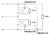
図1には電力計測ユニット15による電流検出の模式図を示す。
FIG. 1 shows a schematic diagram of current detection by the
なお、図中の符号R100は100Vの負荷、R200は200Vの負荷を示す。これら負荷R100,R200には分岐ブレーカ14を通じて交流電源が供給されるが、分岐ブレーカ14は図示を省略している。
In the figure, R100 indicates a 100V load, and R200 indicates a 200V load. Although AC power is supplied to these loads R100 and R200 through the
単相3線式の交流電源は、中性極Nおよび一対の電圧極L1,L2を有し、電圧極L1と中性極Nとの間および中性極Nと電圧極L2との間が100V、電圧極L1と電圧極L2との間が200Vとなっている。 The single-phase three-wire AC power supply has a neutral pole N and a pair of voltage poles L1 and L2. Between the voltage pole L1 and the neutral pole N and between the neutral pole N and the voltage pole L2 100V, and the voltage between the voltage electrode L1 and the voltage electrode L2 is 200V.
分岐ブレーカ14に100Vの負荷R100が接続される場合、上段側の分岐ブレーカ14においては電圧極L1と中性極Nとに接続され、下段側の分岐ブレーカ14においては中性極Nと電圧極L2とに接続され、それぞれ100Vの交流電源が負荷R100に供給される。
When a 100V load R100 is connected to the
分岐ブレーカ14に200Vの負荷R200が接続される場合、分岐ブレーカ14においては電圧極L1と電圧極L2とに接続され、200Vの交流電源が負荷R200に供給される。
When a 200V load R200 is connected to the
そして、100Vの負荷R100が接続される分岐ブレーカ14においては、負荷R100に対して電圧極L1,L2側の配線場所に電流検出手段38が設置される。すなわち、100Vの負荷R100が接続される上段側の分岐ブレーカ14においては、負荷R100と電圧極L1との間の配線場所に電流検出手段38が設置され、また、100Vの負荷R100が接続される下段側の分岐ブレーカ14においては、負荷R100と電圧極L2との間の配線場所に電流検出手段38が設置される。
In the
200Vの負荷R200に接続される分岐ブレーカ14においては、負荷R200と電圧極L2との間の配線場所に電流検出手段38が設置される。
In the
各電流検出手段38の設置は、上述のように決められた配線場所に設置されるように、分岐ブレーカ14に接続される一対の電線26のうち、分岐ブレーカ14の場所や負荷の電圧に応じて予め決められている一方の電線26が、センサ部32の挿通孔36つまり電流検出手段38に挿通される。すなわち、100Vの負荷R100用で上段側の分岐ブレーカ14に接続される一対の電線26のうち、電圧極L1側に接続する一方の電線26が、電流検出手段38に通してから分岐ブレーカ14に接続される。100Vの負荷R100用で下段側の分岐ブレーカ14に接続される一対の電線26のうち、電圧極L2側に接続する一方の電線26が、電流検出手段38に通してから分岐ブレーカ14に接続される。200Vの負荷R200用の一対の電線26のうち、電圧極L2側に接続する一方の電線26が、電流検出手段38に通してから分岐ブレーカ14に接続される。
The installation of each current detection means 38 depends on the location of the
このように、100Vの負荷R100を接続する上段側の分岐ブレーカ14と、100Vの負荷R100を接続する下段側の分岐ブレーカ14と、200Vの負荷R200を接続する分岐ブレーカ14とのそれぞれに応じて、予め決められた配線箇所に電流検出手段38が設置される。
Thus, according to each of the
予め決められた配線箇所に電流検出手段38が設置されることにより、図2に示すように、電圧検出手段41で検出される電圧の位相に対して、100Vの負荷R100と200Vの負荷R200とで電流検出手段38で検出された電流の位相が逆位相となる。すなわち、電圧検出手段41で検出される電圧の位相に対して、電流検出手段38で検出される100Vの負荷R100の電流の位相が同じ向きの位相となり、電流検出手段38で検出される200Vの負荷R200の電流の位相が逆位相となる。
By installing the current detection means 38 at a predetermined wiring location, a 100V load R100 and a 200V load R200 with respect to the phase of the voltage detected by the voltage detection means 41, as shown in FIG. Thus, the phase of the current detected by the current detection means 38 is reversed. That is, the phase of the current of the 100V load R100 detected by the
そして、演算部42は、電圧検出手段41で検出される電圧の位相に対する電流検出手段38で検出される100Vの負荷R100の電流の位相および200Vの負荷R200の電流の位相の情報、電流検出手段38が上段側の分岐ブレーカ14に接続される負荷に流れる電流を検出するのか下段側の分岐ブレーカ14に接続される負荷に流れる電流を検出するのかという情報などを予め保有している。そのため、電圧検出手段41で検出された電圧の位相と電流検出手段38で検出された電流の位相とから負荷の電圧を判断し、判断した負荷の電圧に基づいて電力を演算することができる。
Then, the
次に、電力計測ユニット15による電力計測動作を説明する。
Next, the power measurement operation by the
例えば、上段側の分岐ブレーカ14に接続される100Vの負荷R100で電力が使用されると、負荷R100に対して電圧極L1側に設置されている電流検出手段38により負荷R100に流れる電流が検出され、検出された検出信号が演算部42に入力される。そして、演算部42では、上段側の分岐ブレーカ14に接続される負荷に流れる電流を検出する電流検出手段38からの検出信号であることが分かっているため、図2に示すように、電圧検出手段41で検出される電圧の位相に対して、電流検出手段38からの検出信号の位相が同じ向きの位相となっていれば、100Vの負荷R100であると判断し、100Vの電圧で電力を演算する。
For example, when power is used in a 100V load R100 connected to the
また、下段側の分岐ブレーカ14に接続される100Vの負荷R100で電力が使用されると、負荷R100に対して電圧極L2側に設置されている電流検出手段38により負荷R100に流れる電流が検出され、検出された検出信号が演算部42に入力される。この場合、電圧極L1と中性極Nとの間の電流の位相に対して中性極Nと電圧極L2との間の電流の位相が逆位相となるが、負荷R100に対して電圧極L2側に電流検出手段38が設置されているため、この電流検出手段38で検出される電流の位相は、上段側の分岐ブレーカ14に接続される負荷R100に対して電圧極L1側に設置された電流検出手段38で検出される電流の位相と同じ向きの位相となる。そして、演算部42では、下段側の分岐ブレーカ14に接続される負荷に流れる電流を検出する電流検出手段38からの検出信号であることが分かっているため、図2に示すように、電圧検出手段41で検出される電圧の位相に対して、電流検出手段38からの検出信号の位相が同じ向きの位相となっていれば、100Vの負荷R100であると判断し、100Vの電圧で電力を演算する。
Further, when power is used with a 100V load R100 connected to the
また、分岐ブレーカ14に接続される200Vの負荷R200で電力が使用されると、負荷R200に対して電圧極L2側に設置された電流検出手段38により負荷R200に流れる電流が検出され、検出された検出信号が演算部42に入力される。そして、演算部42では、上段側または下段側の分岐ブレーカ14に接続される負荷に流れる電流を検出する電流検出手段38からの検出信号であることが分かっているため、図2に示すように、電圧検出手段41で検出される電圧の位相に対して、電流検出手段38から検出信号の位相が逆位相となっていれば、200Vの負荷R200であると判断し、200Vの電圧で電力を演算する。
Further, when power is used with a 200V load R200 connected to the
このように、電力計測ユニット15では、電圧検出手段41で検出される電圧の位相に対して100Vの負荷と200Vの負荷とで検出した電流の位相が逆位相となるように電流検出手段38を設置するとともに、電圧検出手段41で検出される電圧の位相に対する電流検出手段38で検出される100Vの負荷R100の電流の位相および200Vの負荷R200の電流の位相の情報を演算部42が予め保有していることにより、演算部42では、電圧検出手段41で検出された電圧の位相と電流検出手段38で検出された電流の位相とから負荷の電圧を自動的に判断し、判断した負荷の電圧に基づいて電力を演算できる。そのため、分岐ブレーカ14に接続される負荷の電圧の設定作業が不要になり、設定間違いがなく、正確な電力の計測ができる。
In this way, in the
なお、図2には電圧の位相と電流の位相とが同じ場合を示したが、負荷回路の影響によって位相が多少ずれていても、演算部42では負荷の電圧を判断できる。
Although FIG. 2 shows the case where the phase of the voltage and the phase of the current are the same, even if the phase is slightly shifted due to the influence of the load circuit, the
また、電圧検出手段41で検出される電圧の位相に対して、電流検出手段38で検出される100Vの負荷R100の電流の位相が逆位相となり、電流検出手段38で検出される200Vの負荷R200の電流の位相が同じ向きの位相となるようにしてもよい。この場合、100Vの負荷R100が接続される上段側の分岐ブレーカ14においては、負荷R100と中性極Nとの間の配線場所に電流検出手段38を設置し、また、100Vの負荷R100が接続される下段側の分岐ブレーカ14においては、負荷R100と中性極Nとの間の配線場所に電流検出手段38を設置し、また、200Vの負荷R200に接続される分岐ブレーカ14においては、負荷R200と電圧極L1との間の配線場所に電流検出手段38を設置すればよい。
Further, the phase of the current of the 100V load R100 detected by the current detection means 38 is opposite to the phase of the voltage detected by the voltage detection means 41, and the 200V load R200 detected by the current detection means 38. The phases of the currents may be in the same direction. In this case, in the
また、電流検出手段38にCTを用いる場合、CTの検出コイルで電流の方向を検出する向きがあるため、電圧検出手段41で検出される電圧の位相に対して100Vの負荷と200Vの負荷とで検出した電流の位相が逆位相となるように、CTの検出コイルで電流の方向を検出する向きを変えるようにしてもよい。 Further, when CT is used for the current detection means 38, there is a direction in which the direction of the current is detected by the CT detection coil, so that a load of 100V and a load of 200V with respect to the phase of the voltage detected by the voltage detection means 41 The direction in which the direction of the current is detected by the CT detection coil may be changed so that the phase of the current detected in step 1 is reversed.
本発明のいくつかの実施形態を説明したが、これらの実施形態は、例として提示したものであり、発明の範囲を限定することは意図していない。これら新規な実施形態は、その他の様々な形態で実施されることが可能であり、発明の要旨を逸脱しない範囲で、種々の省略、置き換え、変更を行うことができる。これら実施形態やその変形は、発明の範囲や要旨に含まれるとともに、特許請求の範囲に記載された発明とその均等の範囲に含まれる。 Although several embodiments of the present invention have been described, these embodiments are presented by way of example and are not intended to limit the scope of the invention. These novel embodiments can be implemented in various other forms, and various omissions, replacements, and changes can be made without departing from the scope of the invention. These embodiments and modifications thereof are included in the scope and gist of the invention, and are included in the invention described in the claims and the equivalents thereof.
10 分電盤
13 導電バー
14 分岐ブレーカ
15 電力計測ユニット
38 電流検出手段
41 電圧検出手段
42 演算部
10 Distribution board
13 Conductive bar
14 Branch breaker
15 Power measurement unit
38 Current detection means
41 Voltage detection means
42 Calculation unit
Claims (2)
導電バーに接続される分岐ブレーカから負荷側に流れる電流を検出するとともに、電圧検出手段で検出される電圧の位相に対して100Vの負荷と200Vの負荷とで検出した電流の位相が逆位相となるように設置される電流検出手段と;
電圧検出手段で検出される電圧の位相に対する電流検出手段で検出される100Vの負荷の電流の位相および200Vの負荷の電流の位相の情報を予め保有しており、電圧検出手段で検出された電圧の位相と電流検出手段で検出された電流の位相とから負荷の電圧を判断し、判断した負荷の電圧に基づいて電力を演算する演算部と;
を具備していることを特徴とする電力計測ユニット。 Voltage detecting means for detecting voltage from a conductive bar that supplies single-phase three-wire AC power;
The current flowing from the branch breaker connected to the conductive bar to the load side is detected, and the phase of the current detected by the 100 V load and the 200 V load is opposite to the phase of the voltage detected by the voltage detecting means. Current detection means installed to be;
Information on the phase of the 100V load current detected by the current detection means and the phase of the 200V load current detected by the current detection means with respect to the phase of the voltage detected by the voltage detection means is stored in advance, and the voltage detected by the voltage detection means A calculation unit that determines the voltage of the load from the phase of the current and the phase of the current detected by the current detection means, and calculates power based on the determined voltage of the load;
An electric power measurement unit comprising:
負荷側の電圧に応じた接続状態となるように導電バーに接続される複数の分岐ブレーカと;
請求項1記載の電力計測ユニットと;
を具備していることを特徴とする分電盤。 A conductive bar for supplying AC power in a single-phase three-wire system;
A plurality of branch breakers connected to the conductive bar so as to be connected according to the voltage on the load side;
A power measuring unit according to claim 1;
A distribution board characterized by comprising:
Priority Applications (1)
| Application Number | Priority Date | Filing Date | Title |
|---|---|---|---|
| JP2012103086A JP5871132B2 (en) | 2012-04-27 | 2012-04-27 | Power measurement unit and distribution board |
Applications Claiming Priority (1)
| Application Number | Priority Date | Filing Date | Title |
|---|---|---|---|
| JP2012103086A JP5871132B2 (en) | 2012-04-27 | 2012-04-27 | Power measurement unit and distribution board |
Publications (2)
| Publication Number | Publication Date |
|---|---|
| JP2013231642A JP2013231642A (en) | 2013-11-14 |
| JP5871132B2 true JP5871132B2 (en) | 2016-03-01 |
Family
ID=49678210
Family Applications (1)
| Application Number | Title | Priority Date | Filing Date |
|---|---|---|---|
| JP2012103086A Active JP5871132B2 (en) | 2012-04-27 | 2012-04-27 | Power measurement unit and distribution board |
Country Status (1)
| Country | Link |
|---|---|
| JP (1) | JP5871132B2 (en) |
Families Citing this family (2)
| Publication number | Priority date | Publication date | Assignee | Title |
|---|---|---|---|---|
| JP6541069B2 (en) * | 2015-09-29 | 2019-07-10 | パナソニックIpマネジメント株式会社 | Distribution board management system and program |
| JP6541068B2 (en) * | 2015-09-29 | 2019-07-10 | パナソニックIpマネジメント株式会社 | Circuit determination method, circuit determination system, and program |
Family Cites Families (3)
| Publication number | Priority date | Publication date | Assignee | Title |
|---|---|---|---|---|
| JP4545081B2 (en) * | 2005-10-31 | 2010-09-15 | 日置電機株式会社 | measuring device |
| KR20090028786A (en) * | 2006-11-27 | 2009-03-19 | 파나소닉 전공 주식회사 | Distribution board |
| JP5946689B2 (en) * | 2012-04-27 | 2016-07-06 | 河村電器産業株式会社 | Distribution board |
-
2012
- 2012-04-27 JP JP2012103086A patent/JP5871132B2/en active Active
Also Published As
| Publication number | Publication date |
|---|---|
| JP2013231642A (en) | 2013-11-14 |
Similar Documents
| Publication | Publication Date | Title |
|---|---|---|
| CN103424597B (en) | For d-c circuit breaker can the current sensing mechanism of detection of ground faults | |
| JP5994973B2 (en) | Distribution board | |
| US10732205B2 (en) | Device for measuring electric currents in electrical conductors | |
| JP5871132B2 (en) | Power measurement unit and distribution board | |
| JP6083017B2 (en) | Adapter for current measurement | |
| JP4500130B2 (en) | Method and apparatus for checking wiring connection of outlet with ground electrode | |
| JP2013183581A (en) | Distribution board | |
| JP2011036050A (en) | Distribution panel | |
| JP2016163363A (en) | Distribution panel | |
| JP6083018B2 (en) | Current measuring member | |
| JP2016163362A (en) | Distribution panel | |
| JP2006092913A (en) | Plug unit with current detector incorporated therein | |
| JP6323778B2 (en) | Distribution board cabinet and distribution board using the same | |
| JP6173739B2 (en) | Distribution board | |
| JP6471990B2 (en) | Conductive bar, distribution board cabinet and distribution board | |
| KR101290170B1 (en) | Dc current detecting apparatus for dc circuit breaker | |
| KR101277225B1 (en) | Current detecting mechanism capable of detecting ground fault for direct current circuit breaker | |
| JP2015198470A (en) | Cabinet for distribution board with measuring unit and distribution board | |
| JP6424547B2 (en) | Distribution board | |
| KR101653227B1 (en) | Connector having a Sensor module and Distributing Board using thereof | |
| JP2015208095A (en) | Current measurement unit and distribution panel using the same | |
| JP6573191B2 (en) | Residential distribution board | |
| JP6350825B2 (en) | Measuring unit and distribution board | |
| JP6340718B2 (en) | Internal device for distribution board and distribution board using the same | |
| JP6432856B2 (en) | Current measuring instruments, cabinets for distribution boards with measuring instruments and distribution boards |
Legal Events
| Date | Code | Title | Description |
|---|---|---|---|
| A621 | Written request for application examination |
Free format text: JAPANESE INTERMEDIATE CODE: A621 Effective date: 20150305 |
|
| TRDD | Decision of grant or rejection written | ||
| A01 | Written decision to grant a patent or to grant a registration (utility model) |
Free format text: JAPANESE INTERMEDIATE CODE: A01 Effective date: 20151216 |
|
| A977 | Report on retrieval |
Free format text: JAPANESE INTERMEDIATE CODE: A971007 Effective date: 20151216 |
|
| A61 | First payment of annual fees (during grant procedure) |
Free format text: JAPANESE INTERMEDIATE CODE: A61 Effective date: 20151229 |
|
| R151 | Written notification of patent or utility model registration |
Ref document number: 5871132 Country of ref document: JP Free format text: JAPANESE INTERMEDIATE CODE: R151 |
|
| R250 | Receipt of annual fees |
Free format text: JAPANESE INTERMEDIATE CODE: R250 |
|
| S111 | Request for change of ownership or part of ownership |
Free format text: JAPANESE INTERMEDIATE CODE: R313113 |
|
| R350 | Written notification of registration of transfer |
Free format text: JAPANESE INTERMEDIATE CODE: R350 |