JP5994973B2 - Distribution board - Google Patents
Distribution board Download PDFInfo
- Publication number
- JP5994973B2 JP5994973B2 JP2012103085A JP2012103085A JP5994973B2 JP 5994973 B2 JP5994973 B2 JP 5994973B2 JP 2012103085 A JP2012103085 A JP 2012103085A JP 2012103085 A JP2012103085 A JP 2012103085A JP 5994973 B2 JP5994973 B2 JP 5994973B2
- Authority
- JP
- Japan
- Prior art keywords
- detection signal
- unit
- groove
- distribution board
- branch
- Prior art date
- Legal status (The legal status is an assumption and is not a legal conclusion. Google has not performed a legal analysis and makes no representation as to the accuracy of the status listed.)
- Expired - Fee Related
Links
Images


Landscapes
- Patch Boards (AREA)
- Distribution Board (AREA)
Description
本発明の実施形態は、電力使用量の計測に対応した分電盤に関する。 Embodiments described herein relate generally to a distribution board that supports measurement of power consumption.
従来、住宅用の分電盤では、主幹ブレーカに導電バーが接続され、複数の分岐ブレーカが導電バーの両側に沿って並設されて導電バーに電気的に接続されている。 Conventionally, in a residential distribution board, a conductive bar is connected to the main breaker, and a plurality of branch breakers are arranged side by side along both sides of the conductive bar and are electrically connected to the conductive bar.
このような分電盤においては、各分岐ブレーカに接続された負荷毎の電力使用量や住宅全体の電力使用量を計測できるようにしたものがある。 In such a distribution board, there is one that can measure the power consumption for each load connected to each branch breaker and the power consumption of the entire house.
この分電盤では、分岐ブレーカと同数の電流センサを用い、各分岐ブレーカにそれぞれ接続される一対の電線のうちの一方の電線を各電流センサに挿通し、各電流センサの出力線を計測ユニットの端子部に接続している。計測ユニットには各分岐ブレーカに対応付けられた複数の端子部があり、各電流センサの出力線を計測ユニットの対応付けられている端子部に接続する必要がある。しかしながら、分岐ブレーカの数が多くなると、電流センサの数も多くなるため、電流センサの配線を計測ユニットの対応付けられている端子部に接続する配線作業が煩雑となり、接続間違えが発生しやすい問題がある。 In this distribution board, the same number of current sensors as branch breakers are used, one of the pair of wires connected to each branch breaker is inserted into each current sensor, and the output line of each current sensor is connected to the measurement unit. Is connected to the terminal. The measurement unit has a plurality of terminal portions associated with each branch breaker, and the output line of each current sensor needs to be connected to the terminal portion associated with the measurement unit. However, as the number of branch breakers increases, the number of current sensors also increases, so the wiring work for connecting the current sensor wiring to the terminal section associated with the measurement unit becomes complicated, and a connection error is likely to occur. There is.
また、基板上に複数の電流センサを設けたセンサユニットを用い、このセンサユニットを導電バーに組み込み、センサユニットの基板と計測ユニットとを接続するようにした分電盤がある。この分電盤では、配線作業の煩雑さや接続間違えの問題が解消されるが、各電流センサで各分岐ブレーカに流れる負荷電流を検出できるように、各電流センサを貫通して分岐ブレーカと接続されるように構成された特殊な導電バーを用いなければならない。さらに、特殊な導電バーの接続が可能なように専用の分岐ブレーカを用いなければならない。 There is also a distribution board in which a sensor unit having a plurality of current sensors on a substrate is used, the sensor unit is incorporated in a conductive bar, and the substrate of the sensor unit and the measurement unit are connected. This distribution board solves the problems of wiring work and incorrect connection, but each current sensor is connected to the branch breaker through each current sensor so that the load current flowing through each branch breaker can be detected. A special conductive bar configured to be used must be used. Furthermore, a dedicated branch breaker must be used so that a special conductive bar can be connected.
上述のように、センサユニットを導電バーに組み込むため、特殊な導電バーや専用の分岐ブレーカを用いなければならず、既存の一般的な導電バーや分岐ブレーカなどの構成部品を使用する分電盤には適用できない問題がある。 As described above, in order to incorporate the sensor unit into the conductive bar, a special conductive bar or a dedicated branch breaker must be used, and a distribution board using existing components such as a general conductive bar and branch breaker Has problems that are not applicable.
本発明が解決しようとする課題は、一般的な構成部品を使用する分電盤に適用可能でありながら、配線作業の煩雑さや接続間違えがなく、電力使用量の計測に対応することができる分電盤を提供することである。 The problem to be solved by the present invention can be applied to a distribution board using general components, but can be used for power consumption measurement without the complexity of wiring work and connection mistakes. It is to provide an electrical panel.
実施形態の分電盤は、筐体、筐体内に配置される複数の分岐ブレーカ、および複数の分岐ブレーカの並設方向に沿って筐体内に配置されるセンサユニットを備えている。センサユニットは、ユニット本体、複数の電流検出手段およびプリント配線基板を有する。ユニット本体には、各分岐ブレーカにそれぞれ接続される一対の電線のうちの一方の電線が挿通される複数の挿通孔が設けられるとともに他方の電線が挿通される複数の挿通溝が設けられる。複数の電流検出手段は、各挿通孔に挿通された各電線に流れる負荷電流に応じた検出信号をそれぞれ出力する。プリント配線基板に検出信号出力部が設けられ、プリント配線基板により各電流検出手段で検出された検出信号を検出信号出力部に伝送する。 The distribution board according to the embodiment includes a housing, a plurality of branch breakers disposed in the housing, and a sensor unit disposed in the housing along a parallel direction of the plurality of branch breakers. The sensor unit has a unit body, a plurality of current detection means, and a printed wiring board. The unit main body, that a plurality of insertion grooves in which a plurality of insertion holes one wire of a pair of wires to be connected to each branch breaker is inserted is inserted Rutotomoni other wire is provided is provided . The plurality of current detection means respectively output detection signals corresponding to load currents flowing through the electric wires inserted into the insertion holes. A detection signal output unit is provided on the printed wiring board, and a detection signal detected by each current detection means by the printed wiring board is transmitted to the detection signal output unit.
本発明によれば、各分岐ブレーカにそれぞれ接続される一対の電線のうちの一方の電線が挿通される複数の挿通孔が設けられたユニット本体、各挿通孔に挿通された各電線に流れる負荷電流に応じた検出信号をそれぞれ出力する複数の電流検出手段、および各電流検出手段で検出された検出信号を検出信号出力部に伝送するプリント配線基板を有するセンサユニットを用いるため、一般的な構成部品を使用する分電盤に適用可能でありながら、配線作業の煩雑さや接続間違えがなく、電力使用量の計測に対応することができる。 According to the present invention, a unit main body provided with a plurality of insertion holes through which one of the pair of electric wires connected to each branch breaker is inserted, and a load flowing through each electric wire inserted into each insertion hole Since a sensor unit having a plurality of current detection units that output detection signals corresponding to currents and a printed wiring board that transmits detection signals detected by the respective current detection units to a detection signal output unit is used, a general configuration While being applicable to a distribution board that uses parts, it is possible to cope with the measurement of power consumption without complication of wiring work and connection mistakes.
以下、第1の実施形態を、図1ないし図5を参照して説明する。 Hereinafter, the first embodiment will be described with reference to FIGS. 1 to 5.
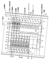
図1および図5に示すように、分電盤10は、壁面に設置される筐体11を有している。この筐体11内に、主幹ブレーカ12、複数の導電バー13、複数の分岐ブレーカ14、計測ユニット15、および複数のセンサユニット16などが配設されている。そして、導電バー13、複数の分岐ブレーカ14、計測ユニット15および複数のセンサユニット16などによって分岐機器部17が構成されている。
As shown in FIGS. 1 and 5, the
筐体11は、壁面に設置されるベース20、およびこのベース20の前面に着脱可能に取り付けられる前面カバー21を有している。前面カバー21の前側は開閉可能な開閉カバー22で覆われている。ベース20の背面の上下部には分電盤10に接続する複数の電線23を壁内から分電盤10内に引き込むための複数の開口部24が形成されている。
The
また、図1に示すように、分岐機器部17は、ベース20に取り付けられる取付板27を有している。この取付板27上に、導電バー13、複数の分岐ブレーカ14、計測ユニット15および複数のセンサユニット16などが一体的に取り付けられている。取付板27には、取付板27の上下方向中央域に導電バー13が左右方向に沿って水平に配置され、この導電バー13の配置域の上下に複数の分岐ブレーカ14を水平方向に並べて取り付ける複数の分岐ブレーカ取付部28が並設されている。
As shown in FIG. 1, the branch device unit 17 has an
また、導電バー13は、主幹ブレーカ12と複数の分岐ブレーカ14とを電気的に接続するもので、単相3線式の交流電源を供給するために中性極用および一対の電圧極用の3つの導電バー13が用いられている。これら3つの導電バー13は、分電盤10の前面から見て前後方向に重なるとともに分電盤10の左右方向に沿って水平に配置されている。
The
また、複数の分岐ブレーカ14は、導電バー13の上下に互いに向きを反対向きとして取付板27の各分岐ブレーカ取付部28に取り付けられているとともに、導電バー13に電気的に接続されている。
In addition, the plurality of
分岐ブレーカ14は、ケース31、このケース31内に配置された回路遮断ユニット(図示せず)を備えている。
The
ケース31は、絶縁性を有する合成樹脂により、ケース31の前面から見て横幅が狭く縦方向に細長い形状に形成されている。ケース31の前面側には回路遮断ユニットを手動操作するためのブレーカハンドル32が配置され、ケース31の前面側から見て長手方向の一端側には導電バー13に電気的に接続される電源側接続部33が形成されているとともに他端側には一対の電線23を接続する電線接続部34が形成されている。
The
電源側接続部33には、各導電バー13が差し込まれる3つの溝が形成されているとともに、3つの溝のうちの2つには導電バー13と電気的に接続される端子が配置されている。そして、分岐ブレーカ14に接続される負荷側が100V仕様の場合と200V仕様の場合とに応じて、端子が配置される溝が異なっているか切り換えられるように構成されている。
The power supply
電線接続部34は、負荷側に接続される一対の電線23を差し込む一対の差込孔35を有している。これら差込孔35内には差し込まれた電線23に電気接続状態で抜け止めする鎖錠端子が配設されている。そして、分岐ブレーカ14の一対の差込孔35は、導電バー13に対して反対側であって、ベース20の開口部24側に向けられている。なお、電線23には、導電線を被覆部で被覆した被覆電線が用いられている。
The electric
回路遮断ユニットは、電源側接続部33の端子と電線接続部34の鎖錠端子との間の接続回路を開閉可能とするもので、ブレーカハンドル32の操作に応じて接続回路を開閉するとともに、接続回路の閉成状態で設定値以上の過電流が流れたときに接続回路を自動的に開成するように構成されている。
The circuit breaker unit can open and close the connection circuit between the terminal of the power supply
また、計測ユニット15は、導電バー13の下側で複数の分岐ブレーカ14と並んで取付板27上に取り付けられている。取付板27上への計測ユニット15の取り付けには分岐ブレーカ取付部28が利用されている。また、計測ユニット15は、分岐ブレーカ14と同様に、導電バー13に電気的に接続され、電力の供給を受ける。さらに、計測ユニット15は、各センサユニット16と電気的に接続されるコネクタを有する一対のケーブル(図示せず)を備えている。
The
そして、計測ユニット15は、センサユニット16で検出される各電線23に流れる負荷電流に応じた検出信号、および主幹ブレーカ12側に流れる負荷電流に応じた検出信号を取得して処理し、各分岐ブレーカ14に接続された負荷毎の電力使用量や、住宅全体の電気使用量を計測し、計測結果を分電盤10の外部に設置される例えばホームゲートウェイなどの機器に送信する。
Then, the
また、センサユニット16は、上段側の複数の分岐ブレーカ14の並設方向に沿って配置されるセンサユニット16a、および下段側の複数の分岐ブレーカ14の並設方向に沿って配置されるセンサユニット16bを有している。これらセンサユニット16a,16bはそれぞれ取付板27に着脱可能に取り付けられている。
The
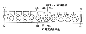
図1ないし図3に示すように、センサユニット16は、ユニット本体38、ユニット本体38内に収容されたプリント配線基板39を有している。さらに、プリント配線基板39には、複数の電流検出手段(分岐電流検出手段)40、出力コネクタ41および入力コネクタ42が搭載されている。
As shown in FIGS. 1 to 3, the
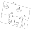
ユニット本体38は、絶縁性を有する例えば合成樹脂製で細長い平板状に形成されている。ユニット本体38には、長手方向に沿って、各分岐ブレーカ14にそれぞれ接続される一対の電線23のうちの予め決められている一方の電線23が挿通される複数の挿通孔44が設けられているとともに他方の電線23が挿通される複数の挿通溝45が設けられている。
The unit
挿通孔44は、ユニット本体38の前後に貫通する円形孔に形成されている。
The
挿通溝45は、ユニット本体38の前後に貫通するとともに分岐ブレーカ14に対向するユニット本体38の縁部側に対して反対の縁部側に開口されたU字形溝に形成されている。挿通溝45は、ユニット本体38の縁部側に開口された溝入口部45a、およびこの溝入口部45aの奥側の溝底部45bを有し、溝入口部45a側の溝幅が溝底部45b側の溝幅より狭い関係を有している。すなわち、溝入口部45a側の溝幅は電線23の直径(被覆部の直径)より狭く、溝底部45b側の溝幅は電線23の直径(被覆部の直径)より広く形成されている。
The
各挿通溝45はそれぞれ隣り合う挿通孔44の間に位置され、複数の挿通孔44と複数の挿通溝45とが千鳥状に位置されている。さらに、複数の挿通孔44と複数の挿通溝45とは、各分岐ブレーカ14にそれぞれ接続される一対の電線23と同じピッチで設けられている。すなわち、分岐ブレーカ14に接続される一対の電線23が挿通する挿通孔44と挿通溝45との中心間の間隔が、その分岐ブレーカ14に接続された一対の電線23の中心間の間隔と同じ寸法とされている。さらに、取付板27に分岐ブレーカ14およびセンサユニット16が取り付けられた状態では、分岐ブレーカ14に接続される一対の電線23の接続位置とその一対の電線23が挿通される挿通孔44および挿通溝45の位置とが上下方向に一致されている。
Each
プリント配線基板39は、一面に配線パターンが形成された配線面39aを有し、ユニット本体38の複数の挿通孔44および複数の挿通溝45に対応した位置に複数の挿通孔39bおよび複数の挿通溝39cがそれぞれ形成されている。プリント配線基板39の一端には出力コネクタ41が実装される検出信号出力部46が設けられ、他端には入力コネクタ42が実装される検出信号入力部47が設けられている。配線パターンは、各電流検出手段40毎および検出信号入力部47毎に設けられ、それぞれ検出信号出力部46の出力コネクタ41に接続されている。
The printed wiring board 39 has a
電流検出手段40は、例えばCT(Current Transformer)で構成され、各挿通孔44に挿通された各電線23に流れる負荷電流に応じた検出信号をそれぞれ出力する。各電流検出手段40はプリント配線基板39の各挿通孔39aの周囲に配置されて配線パターンに電気的に接続されている。そして、電線23に負荷電流が流れると、負荷電流に応じた検出信号がCTの検出コイルに誘起され、この検出信号が配線パターンを通じて検出信号出力部46に伝送される。
The current detection means 40 is composed of, for example, a CT (Current Transformer), and outputs a detection signal corresponding to the load current flowing through each
また、図4に示すように、主幹ブレーカ12には、単相3線式の交流電源を供給するための3本の電線50が接続される。3本の電線50のうち、1本は中性線で、残りの2本は電圧線である。
As shown in FIG. 4, the main breaker 12 is connected with three
また、分電盤10は、主幹ブレーカ12側に流れる負荷電流に応じた検出信号を出力するための主幹電流検出手段53を備えている。主幹電流検出手段53は、例えばCT(Current Transformer)で構成されている検出部54、および上段側のセンサユニット16aの入力コネクタ42に接続されるコネクタ部55を有している。検出部54にはいずれか1本の電圧線である電線50が挿通されている。そして、電線50に負荷電流が流れると、負荷電流に応じた検出信号が検出部54を構成するCTの検出コイルに誘起され、この検出信号がコネクタ部55から入力コネクタ42およびプリント回線基板39の配線パターンを通じて検出信号出力部46に伝送される。
Further, the
そして、分電盤10の施工時において、各負荷毎の一対の電線23をベース20の開口部24を通じてベース20の前側に引き込んで各分岐ブレーカ14に接続する際、一対の電線23のうちの予め決められている一方の電線23を挿通孔44に挿通させるとともに他方の電線23を挿通溝45に挿通させる。一方の電線23を挿通孔44に挿通させるには、一方の電線23の先端を挿通孔44に差し込む作業が必要となるが、他方の電線23を挿通溝45に挿通させるには、他方の電線23の中間部を溝入口部45a側から溝底部45b側に移動させればよいため、配線作業性がよい。
When the
センサユニット16が取付板27に取り付けられた状態で各電線23をセンサユニット16に挿通させる配線作業を行ってもよいし、センサユニット16を取付板27から外した状態で各電線23をセンサユニット16に挿通させる配線作業を行った後、センサユニット16を取付板27に取り付けてもよい。
A wiring operation may be performed in which each
センサユニット16(上下のセンサユニット16a,16b)の出力コネクタ41には、計測ユニット15と配線するケーブルのコネクタを接続する。
A connector of a cable to be wired to the
また、図4に示すように、電線50を主幹ブレーカ12に接続する際、いずれか1つの電圧線である電線50を主幹電流検出手段53に挿通させ、この主幹電流検出手段53のコネクタ部を入力コネクタ42に接続する。
As shown in FIG. 4, when connecting the
そして、分電盤10の使用時においては、各分岐ブレーカ14に接続された電線23を通じて負荷側で電力が使用され、電線23に負荷電流が流れると、負荷電流に応じた検出信号が電流検出手段40に誘起され、この検出信号がプリント配線基板39の配線パターンを通じて検出信号出力部46に伝送されるとともに出力コネクタ41やケーブルを通じて計測ユニット15に伝送される。
When the
さらに、負荷側で電力が使用され、主幹ブレーカ12に接続されている電線50に負荷電流が流れると、負荷電流に応じた検出信号が主幹電流検出手段53に誘起され、この検出信号がセンサユニット16の入力コネクタ42およびプリント配線基板39の配線パターンを通じて検出信号出力部46に伝送されるとともに出力コネクタ41やケーブルを通じて計測ユニット15に伝送される。
Further, when electric power is used on the load side and a load current flows through the
計測ユニット15では、各分岐ブレーカ14に流れる負荷電流に対応した検出信号を個別に取得するとともに、主幹ブレーカ12に流れる負荷電流に対応した検出信号を取得する。これにより、計測ユニット15では、各分岐ブレーカ14に電線23で接続された負荷毎の電力使用量や、住宅全体の電気使用量を計測し、計測結果を分電盤10の外部に設置される例えばホームゲートウェイなどの機器に送信する。
In the
このように構成された分電盤10では、センサユニット16を用いることにより、特殊な導電バーや専用の分岐ブレーカなどを用いることなく、既存の一般的な導電バー13や分岐ブレーカ14などの構成部品を使用する分電盤10に適用可能でありながら、配線作業の煩雑さや接続間違えがなく、電力使用量の計測に対応することができる分電盤10を提供できる。
In the
そのため、センサユニット16を既存の分電盤10に適用し、電力使用量の計測に対応させることができる。
Therefore, the
また、センサユニット16では、各分岐ブレーカ14にそれぞれ接続される一対の電線23のうちの一方の電線23が挿通される複数の挿通孔44が設けられたユニット本体38、各挿通孔44に挿通された各電線23に流れる負荷電流に応じた検出信号をそれぞれ出力する複数の電流検出手段40、および各電流検出手段40で検出された検出信号を検出信号出力部46に伝送するプリント配線基板39を有するため、分岐ブレーカ14毎に接続された電線23に流れる負荷電流の検出、検出された検出電流の個別の伝送および出力ができる。
Further, in the
ユニット本体38には、各分岐ブレーカ14にそれぞれ接続される一対の電線23のうちの他方の電線23が挿通される複数の挿通溝45が設けられているため、他方の電線23を挿通溝45で保持でき、しかも、他方の電線23を挿通溝45で容易に挿通させることができる。
Since the unit
各分岐ブレーカ14に接続していく各一対の電線23をセンサユニット16の各挿通孔44および各挿通溝45に挿通させていくことにより、多数の電線23を順序良く整列させることができ、配線作業性がよいとともに、配線間違いの発生を防止できる。
By inserting each pair of
複数の挿通溝45は、複数の分岐ブレーカ14に対向するユニット本体38の縁部側に対して反対の縁部側に開口されているため、電線23の取り回しがよく、配線作業を容易にできる。
Since the plurality of
挿通溝45の溝入口部45aの溝幅が溝底部45b側の溝幅より狭く、さらに、溝入口部45a側の溝幅は電線23の直径(被覆部の直径)より狭く、溝底部45b側の溝幅は電線23の直径(被覆部の直径)より広いため、挿通溝45に挿通させた電線23を挿通溝45内に保持できる。そのため、電線23が挿通溝45から外れて動き、配線作業の邪魔になるのを防止できる。
The groove width of the
挿通溝45は、それぞれ隣り合う挿通孔44の間に位置されているため、複数の分岐ブレーカ14の並設方向の設置範囲内に対応した限られた寸法内に、挿通孔44や電流検出手段40と挿通溝45とが干渉することなく配置することができ、センサユニット16を小形化できる。
Since the
複数の挿通孔44および複数の挿通溝45は、各分岐ブレーカ14にそれぞれ接続される一対の電線23と同じピッチで設けられているため、各分岐ブレーカ14にそれぞれ接続される一対の電線23を平行状態に整列させることができる。
Since the plurality of insertion holes 44 and the plurality of
分岐ブレーカ14に接続される一対の電線23の接続位置とその一対の電線23が挿通される挿通孔44および挿通溝45の位置とが上下方向に一致されているため、各分岐ブレーカ14にそれぞれ接続される一対の電線23を平行状態に整列させることができる。
Since the connection position of the pair of
また、プリント配線基板39は、主幹電流検出手段53で検出された検出信号についても検出信号入力部47から入力して検出信号出力部46に伝送することができる。
Further, the printed wiring board 39 can also input a detection signal detected by the main current detection means 53 from the detection
また、筐体11には、センサユニット16の後方に電線23を通す開口部24が形成されているため、電線23の配線作業を容易にできるとともに、電線23を無理に曲げるなどの負担がかからないようにできる。
In addition, since the
次に、図6に第2の実施形態を示す。なお、前記実施形態と同じ構成および作用については同じ符号を用いてその説明を省略する。 Next, FIG. 6 shows a second embodiment. In addition, about the same structure and effect | action as the said embodiment, the description is abbreviate | omitted using the same code | symbol.
センサユニット16の挿通溝45は、溝入口部45a側の溝幅が溝底部45b側の溝幅より狭い関係を有している。具体的には、挿通溝45の全体として溝幅は溝入口部45a側から溝底部45b側に亘って同じ寸法としているが、溝入口部45a側の両側に溝内方へ突出する突起58が設けられている。両側の突起58間の寸法は、電線23の直径(被覆部の直径)より狭くなっている。したがって、両側の突起58によって、溝入口部45a側の溝幅が溝底部45b側の溝幅より狭い関係が形成されている。この場合にも、挿通溝45に挿通させた電線23を挿通溝45内に保持できる。
The
本発明のいくつかの実施形態を説明したが、これらの実施形態は、例として提示したものであり、発明の範囲を限定することは意図していない。これら新規な実施形態は、その他の様々な形態で実施されることが可能であり、発明の要旨を逸脱しない範囲で、種々の省略、置き換え、変更を行うことができる。これら実施形態やその変形は、発明の範囲や要旨に含まれるとともに、特許請求の範囲に記載された発明とその均等の範囲に含まれる。 Although several embodiments of the present invention have been described, these embodiments are presented by way of example and are not intended to limit the scope of the invention. These novel embodiments can be implemented in various other forms, and various omissions, replacements, and changes can be made without departing from the scope of the invention. These embodiments and modifications thereof are included in the scope and gist of the invention, and are included in the invention described in the claims and the equivalents thereof.
10 分電盤
11 筐体
12 主幹ブレーカ
14 分岐ブレーカ
16 センサユニット
23 電線
24 開口部
38 ユニット本体
39 プリント配線基板
40 電流検出手段
44 挿通孔
45 挿通溝
45a 溝入口部
45b 溝底部
46 検出信号出力部
47 検出信号入力部
53 主幹電流検出手段
10 Distribution board
11 Enclosure
12 Core breaker
14 Branch breaker
16 Sensor unit
23 Electric wire
24 opening
38 Unit body
39 Printed circuit board
40 Current detection means
44 Insertion hole
45 Insertion groove
45a Groove entrance
45b groove bottom
46 Detection signal output section
47 Detection signal input section
53 Main current detection means
Claims (7)
筐体内に配置される複数の分岐ブレーカと;
各分岐ブレーカにそれぞれ接続される一対の電線のうちの一方の電線が挿通される複数の挿通孔が設けられるとともに他方の電線が挿通される複数の挿通溝が設けられたユニット本体、各挿通孔に挿通された各電線に流れる負荷電流に応じた検出信号をそれぞれ出力する複数の電流検出手段、および検出信号出力部が設けられ各電流検出手段で検出された検出信号を検出信号出力部に伝送するプリント配線基板を有し、複数の分岐ブレーカの並設方向に沿って筐体内に配置されるセンサユニットと;
を具備していることを特徴とする分電盤。 A housing;
A plurality of branch breakers arranged in the housing;
A pair of one of a plurality of insertion grooves unit body provided with a plurality of through holes is inserted Rutotomoni other wire provided electrical wire is inserted among the wires to be connected to each branch breakers, each inserted A plurality of current detection means each for outputting a detection signal corresponding to a load current flowing through each electric wire inserted into the hole, and a detection signal output section are provided, and the detection signal detected by each current detection means is provided as a detection signal output section A sensor unit that has a printed wiring board for transmission and is arranged in the housing along the direction in which the plurality of branch breakers are arranged;
Panelboard, characterized in that it comprises a.
ことを特徴とする請求項1記載の分電盤。 A plurality of insertion grooves, distribution board according to claim 1, characterized in that it is open on the edge side opposite to the edge side of the unit body opposite the plurality of branch breakers.
ことを特徴とする請求項2記載の分電盤。 The distribution board according to claim 2 , wherein each insertion groove has a groove inlet portion and a groove bottom portion, and the groove width on the groove inlet side is narrower than the groove width on the groove bottom portion side.
ことを特徴とする請求項1ないし3いずれか一記載の分電盤。 The distribution board according to any one of claims 1 to 3 , wherein each insertion groove is positioned between adjacent insertion holes.
ことを特徴とする請求項4記載の分電盤。 The distribution board according to claim 4 , wherein the plurality of insertion holes and the plurality of insertion grooves are provided at the same pitch as a pair of electric wires connected to each branch breaker.
主幹ブレーカ側に流れる負荷電流に応じた検出信号を出力する主幹電流検出手段と;
を具備し、
プリント配線基板は、主幹電流検出手段で検出された検出信号を入力する検出信号入力部が設けられ、主幹電流検出手段で検出された検出信号を検出信号出力部に伝送する
ことを特徴とする請求項1ないし5いずれか一記載の分電盤。 With the main breaker;
Main current detection means for outputting a detection signal corresponding to the load current flowing on the main breaker side;
Comprising
The printed wiring board is provided with a detection signal input unit for inputting a detection signal detected by the main current detection unit, and transmits the detection signal detected by the main current detection unit to the detection signal output unit. Item 6. The distribution board according to any one of Items 1 to 5 .
ことを特徴とする請求項1ないし6いずれか一記載の分電盤。 The distribution board according to any one of claims 1 to 6 , wherein the casing is formed with an opening through which an electric wire passes behind the sensor unit.
Priority Applications (1)
| Application Number | Priority Date | Filing Date | Title |
|---|---|---|---|
| JP2012103085A JP5994973B2 (en) | 2012-04-27 | 2012-04-27 | Distribution board |
Applications Claiming Priority (1)
| Application Number | Priority Date | Filing Date | Title |
|---|---|---|---|
| JP2012103085A JP5994973B2 (en) | 2012-04-27 | 2012-04-27 | Distribution board |
Publications (2)
| Publication Number | Publication Date |
|---|---|
| JP2013233023A JP2013233023A (en) | 2013-11-14 |
| JP5994973B2 true JP5994973B2 (en) | 2016-09-21 |
Family
ID=49678996
Family Applications (1)
| Application Number | Title | Priority Date | Filing Date |
|---|---|---|---|
| JP2012103085A Expired - Fee Related JP5994973B2 (en) | 2012-04-27 | 2012-04-27 | Distribution board |
Country Status (1)
| Country | Link |
|---|---|
| JP (1) | JP5994973B2 (en) |
Families Citing this family (6)
| Publication number | Priority date | Publication date | Assignee | Title |
|---|---|---|---|---|
| JP6299252B2 (en) * | 2014-02-10 | 2018-03-28 | 東京電力ホールディングス株式会社 | Self-powered current measuring device |
| JP6400431B2 (en) * | 2014-10-23 | 2018-10-03 | 日東工業株式会社 | Distribution board measuring device |
| JP6598108B2 (en) * | 2015-08-05 | 2019-10-30 | パナソニックIpマネジメント株式会社 | Current measuring device and distribution board using the same |
| KR101822808B1 (en) * | 2015-08-13 | 2018-01-29 | 주식회사 루텍 | Measuring Instrument For Multiple Single Phase Circuit |
| JP6920149B2 (en) * | 2017-09-13 | 2021-08-18 | 河村電器産業株式会社 | Residential distribution board |
| CN107942699A (en) * | 2017-12-14 | 2018-04-20 | 宁波智轩物联网科技有限公司 | A kind of standard trajectory intelligent domestic system |
Family Cites Families (7)
| Publication number | Priority date | Publication date | Assignee | Title |
|---|---|---|---|---|
| JPS5795015U (en) * | 1980-12-02 | 1982-06-11 | ||
| JP2991875B2 (en) * | 1992-11-17 | 1999-12-20 | 松下電工株式会社 | Switchboard |
| JP3045726U (en) * | 1997-07-29 | 1998-02-13 | 株式会社昭電 | Switchboard |
| JP2001103621A (en) * | 1999-09-28 | 2001-04-13 | Osaki Electric Co Ltd | Distribution board with measuring function |
| JP4552929B2 (en) * | 2006-11-27 | 2010-09-29 | パナソニック電工株式会社 | Distribution board |
| JP2009033914A (en) * | 2007-07-30 | 2009-02-12 | Toshiba Lighting & Technology Corp | Distribution panel |
| US20110074383A1 (en) * | 2009-09-29 | 2011-03-31 | Astec International Limited | Assemblies and Methods for Sensing Current Through Semiconductor Device Leads |
-
2012
- 2012-04-27 JP JP2012103085A patent/JP5994973B2/en not_active Expired - Fee Related
Also Published As
| Publication number | Publication date |
|---|---|
| JP2013233023A (en) | 2013-11-14 |
Similar Documents
| Publication | Publication Date | Title |
|---|---|---|
| JP5994973B2 (en) | Distribution board | |
| JP2009207237A (en) | Distribution switchboard | |
| JP2015186357A (en) | distribution board | |
| KR101565893B1 (en) | current sensor capable of easily attaching and detaching for power distribution panel | |
| JP6083017B2 (en) | Adapter for current measurement | |
| JP6083018B2 (en) | Current measuring member | |
| JP2013183581A (en) | Distribution board | |
| JP6519764B2 (en) | Measurement unit and distribution board | |
| JP2016163362A (en) | Distribution panel | |
| JP2016163363A (en) | Distribution panel | |
| JP5871132B2 (en) | Power measurement unit and distribution board | |
| JP6323778B2 (en) | Distribution board cabinet and distribution board using the same | |
| JP5804272B2 (en) | Distribution board | |
| JP4979062B2 (en) | Signal transmission circuit device | |
| JP6173739B2 (en) | Distribution board | |
| JP6350825B2 (en) | Measuring unit and distribution board | |
| JP2012074336A (en) | Circuit breaker ct output signal leader line accommodation structure | |
| KR101653227B1 (en) | Connector having a Sensor module and Distributing Board using thereof | |
| JP6340718B2 (en) | Internal device for distribution board and distribution board using the same | |
| JP6193309B2 (en) | Distribution board | |
| JP6573191B2 (en) | Residential distribution board | |
| JP2015061443A (en) | Distribution board | |
| JP4493621B2 (en) | Current converter | |
| JP5946689B2 (en) | Distribution board | |
| JP2014032083A (en) | Terminal board |
Legal Events
| Date | Code | Title | Description |
|---|---|---|---|
| A621 | Written request for application examination |
Free format text: JAPANESE INTERMEDIATE CODE: A621 Effective date: 20150305 |
|
| A977 | Report on retrieval |
Free format text: JAPANESE INTERMEDIATE CODE: A971007 Effective date: 20160128 |
|
| A131 | Notification of reasons for refusal |
Free format text: JAPANESE INTERMEDIATE CODE: A131 Effective date: 20160210 |
|
| A521 | Written amendment |
Free format text: JAPANESE INTERMEDIATE CODE: A523 Effective date: 20160408 |
|
| TRDD | Decision of grant or rejection written | ||
| A01 | Written decision to grant a patent or to grant a registration (utility model) |
Free format text: JAPANESE INTERMEDIATE CODE: A01 Effective date: 20160727 |
|
| A61 | First payment of annual fees (during grant procedure) |
Free format text: JAPANESE INTERMEDIATE CODE: A61 Effective date: 20160809 |
|
| R151 | Written notification of patent or utility model registration |
Ref document number: 5994973 Country of ref document: JP Free format text: JAPANESE INTERMEDIATE CODE: R151 |
|
| LAPS | Cancellation because of no payment of annual fees |