EP3255401B1 - Capteur de pression piézoélectrique destiné à la mesure de hautes pressions - Google Patents
Capteur de pression piézoélectrique destiné à la mesure de hautes pressions Download PDFInfo
- Publication number
- EP3255401B1 EP3255401B1 EP17173611.9A EP17173611A EP3255401B1 EP 3255401 B1 EP3255401 B1 EP 3255401B1 EP 17173611 A EP17173611 A EP 17173611A EP 3255401 B1 EP3255401 B1 EP 3255401B1
- Authority
- EP
- European Patent Office
- Prior art keywords
- pressure sensor
- housing
- crystal element
- sensor according
- piezoelectric pressure
- Prior art date
- Legal status (The legal status is an assumption and is not a legal conclusion. Google has not performed a legal analysis and makes no representation as to the accuracy of the status listed.)
- Active
Links
- 239000013078 crystal Substances 0.000 claims description 44
- 229910000154 gallium phosphate Inorganic materials 0.000 claims description 2
- GQYHUHYESMUTHG-UHFFFAOYSA-N lithium niobate Chemical compound [Li+].[O-][Nb](=O)=O GQYHUHYESMUTHG-UHFFFAOYSA-N 0.000 claims description 2
- 239000012528 membrane Substances 0.000 description 28
- 210000004379 membrane Anatomy 0.000 description 26
- 238000002485 combustion reaction Methods 0.000 description 9
- 230000000694 effects Effects 0.000 description 6
- 239000010453 quartz Substances 0.000 description 5
- VYPSYNLAJGMNEJ-UHFFFAOYSA-N silicon dioxide Inorganic materials O=[Si]=O VYPSYNLAJGMNEJ-UHFFFAOYSA-N 0.000 description 5
- 239000012634 fragment Substances 0.000 description 2
- 238000007789 sealing Methods 0.000 description 2
- 230000004308 accommodation Effects 0.000 description 1
- 230000015572 biosynthetic process Effects 0.000 description 1
- 239000004020 conductor Substances 0.000 description 1
- 238000010276 construction Methods 0.000 description 1
- 238000009795 derivation Methods 0.000 description 1
- 239000007789 gas Substances 0.000 description 1
- 239000000463 material Substances 0.000 description 1
- 230000000284 resting effect Effects 0.000 description 1
- 230000000717 retained effect Effects 0.000 description 1
- 230000035945 sensitivity Effects 0.000 description 1
- 230000001960 triggered effect Effects 0.000 description 1
Images
Classifications
-
- G—PHYSICS
- G01—MEASURING; TESTING
- G01L—MEASURING FORCE, STRESS, TORQUE, WORK, MECHANICAL POWER, MECHANICAL EFFICIENCY, OR FLUID PRESSURE
- G01L23/00—Devices or apparatus for measuring or indicating or recording rapid changes, such as oscillations, in the pressure of steam, gas, or liquid; Indicators for determining work or energy of steam, internal-combustion, or other fluid-pressure engines from the condition of the working fluid
- G01L23/08—Devices or apparatus for measuring or indicating or recording rapid changes, such as oscillations, in the pressure of steam, gas, or liquid; Indicators for determining work or energy of steam, internal-combustion, or other fluid-pressure engines from the condition of the working fluid operated electrically
- G01L23/10—Devices or apparatus for measuring or indicating or recording rapid changes, such as oscillations, in the pressure of steam, gas, or liquid; Indicators for determining work or energy of steam, internal-combustion, or other fluid-pressure engines from the condition of the working fluid operated electrically by pressure-sensitive members of the piezoelectric type
-
- G—PHYSICS
- G01—MEASURING; TESTING
- G01L—MEASURING FORCE, STRESS, TORQUE, WORK, MECHANICAL POWER, MECHANICAL EFFICIENCY, OR FLUID PRESSURE
- G01L9/00—Measuring steady of quasi-steady pressure of fluid or fluent solid material by electric or magnetic pressure-sensitive elements; Transmitting or indicating the displacement of mechanical pressure-sensitive elements, used to measure the steady or quasi-steady pressure of a fluid or fluent solid material, by electric or magnetic means
- G01L9/0041—Transmitting or indicating the displacement of flexible diaphragms
- G01L9/008—Transmitting or indicating the displacement of flexible diaphragms using piezoelectric devices
-
- G—PHYSICS
- G01—MEASURING; TESTING
- G01L—MEASURING FORCE, STRESS, TORQUE, WORK, MECHANICAL POWER, MECHANICAL EFFICIENCY, OR FLUID PRESSURE
- G01L1/00—Measuring force or stress, in general
- G01L1/16—Measuring force or stress, in general using properties of piezoelectric devices
-
- G—PHYSICS
- G01—MEASURING; TESTING
- G01L—MEASURING FORCE, STRESS, TORQUE, WORK, MECHANICAL POWER, MECHANICAL EFFICIENCY, OR FLUID PRESSURE
- G01L19/00—Details of, or accessories for, apparatus for measuring steady or quasi-steady pressure of a fluent medium insofar as such details or accessories are not special to particular types of pressure gauges
- G01L19/0061—Electrical connection means
- G01L19/0069—Electrical connection means from the sensor to its support
-
- G—PHYSICS
- G01—MEASURING; TESTING
- G01L—MEASURING FORCE, STRESS, TORQUE, WORK, MECHANICAL POWER, MECHANICAL EFFICIENCY, OR FLUID PRESSURE
- G01L19/00—Details of, or accessories for, apparatus for measuring steady or quasi-steady pressure of a fluent medium insofar as such details or accessories are not special to particular types of pressure gauges
- G01L19/06—Means for preventing overload or deleterious influence of the measured medium on the measuring device or vice versa
- G01L19/0618—Overload protection
-
- G—PHYSICS
- G01—MEASURING; TESTING
- G01L—MEASURING FORCE, STRESS, TORQUE, WORK, MECHANICAL POWER, MECHANICAL EFFICIENCY, OR FLUID PRESSURE
- G01L19/00—Details of, or accessories for, apparatus for measuring steady or quasi-steady pressure of a fluent medium insofar as such details or accessories are not special to particular types of pressure gauges
- G01L19/06—Means for preventing overload or deleterious influence of the measured medium on the measuring device or vice versa
- G01L19/0672—Leakage or rupture protection or detection
-
- G—PHYSICS
- G01—MEASURING; TESTING
- G01L—MEASURING FORCE, STRESS, TORQUE, WORK, MECHANICAL POWER, MECHANICAL EFFICIENCY, OR FLUID PRESSURE
- G01L19/00—Details of, or accessories for, apparatus for measuring steady or quasi-steady pressure of a fluent medium insofar as such details or accessories are not special to particular types of pressure gauges
- G01L19/14—Housings
-
- G—PHYSICS
- G01—MEASURING; TESTING
- G01L—MEASURING FORCE, STRESS, TORQUE, WORK, MECHANICAL POWER, MECHANICAL EFFICIENCY, OR FLUID PRESSURE
- G01L23/00—Devices or apparatus for measuring or indicating or recording rapid changes, such as oscillations, in the pressure of steam, gas, or liquid; Indicators for determining work or energy of steam, internal-combustion, or other fluid-pressure engines from the condition of the working fluid
- G01L23/22—Devices or apparatus for measuring or indicating or recording rapid changes, such as oscillations, in the pressure of steam, gas, or liquid; Indicators for determining work or energy of steam, internal-combustion, or other fluid-pressure engines from the condition of the working fluid for detecting or indicating knocks in internal-combustion engines; Units comprising pressure-sensitive members combined with ignitors for firing internal-combustion engines
- G01L23/221—Devices or apparatus for measuring or indicating or recording rapid changes, such as oscillations, in the pressure of steam, gas, or liquid; Indicators for determining work or energy of steam, internal-combustion, or other fluid-pressure engines from the condition of the working fluid for detecting or indicating knocks in internal-combustion engines; Units comprising pressure-sensitive members combined with ignitors for firing internal-combustion engines for detecting or indicating knocks in internal combustion engines
- G01L23/222—Devices or apparatus for measuring or indicating or recording rapid changes, such as oscillations, in the pressure of steam, gas, or liquid; Indicators for determining work or energy of steam, internal-combustion, or other fluid-pressure engines from the condition of the working fluid for detecting or indicating knocks in internal-combustion engines; Units comprising pressure-sensitive members combined with ignitors for firing internal-combustion engines for detecting or indicating knocks in internal combustion engines using piezoelectric devices
-
- G—PHYSICS
- G01—MEASURING; TESTING
- G01L—MEASURING FORCE, STRESS, TORQUE, WORK, MECHANICAL POWER, MECHANICAL EFFICIENCY, OR FLUID PRESSURE
- G01L9/00—Measuring steady of quasi-steady pressure of fluid or fluent solid material by electric or magnetic pressure-sensitive elements; Transmitting or indicating the displacement of mechanical pressure-sensitive elements, used to measure the steady or quasi-steady pressure of a fluid or fluent solid material, by electric or magnetic means
- G01L9/08—Measuring steady of quasi-steady pressure of fluid or fluent solid material by electric or magnetic pressure-sensitive elements; Transmitting or indicating the displacement of mechanical pressure-sensitive elements, used to measure the steady or quasi-steady pressure of a fluid or fluent solid material, by electric or magnetic means by making use of piezoelectric devices, i.e. electric circuits therefor
Definitions
- the invention relates to a piezoelectric pressure sensor, which is suitable for measuring high pressures, with a housing that can be inserted into a measuring bore and a piezoelectric measuring element that is arranged between a sensor membrane arranged on the front of the housing and an inner housing shoulder, the piezoelectric measuring element consisting of a single crystal element consists.
- Piezoelectric pressure sensors which are used, for example, to measure pressure in the combustion chambers of high-performance internal combustion engines, are exposed to high temperature and pressure loads, pressure peaks in the range of up to 1000 bar can occur. It is important to improve the breakthrough security and tightness of the pressure sensors.
- the piezoelectric measuring element breaks, which in conventional pressure sensors usually consists of a stack of disk-shaped or ring-shaped crystal elements (see e.g. DE 34 23 711 A1 or DE 38 38 014 A1 ) or from several standing, rod-shaped crystal elements (see e.g. AT 504 485 B1 ), no parts of the pressure sensor can get into the combustion chamber of the internal combustion engine and cause damage there.
- the WO 2009/015941 A1 a piezoelectric pressure sensor which has a sensor membrane with a central pressure stamp which is attached to a pressure piece.
- Several rod-shaped, piezoelectric crystal elements are arranged preloaded between the pressure piece and an inner housing shoulder in order to utilize the transverse piezo effect. If the piezoelectric crystal elements break as a result of overloading, a sealing shoulder of the pressure piece comes to rest against a sealing seat inside the sensor housing in order to prevent hot gases from escaping through the pressure sensor.
- the relatively complicated structure of the pressure sensor and its great overall height are disadvantageous
- a pressure sensor with overload protection has become known.
- the pressure plunger of a sensor membrane which acts on a piezoelectric measuring element arranged in a tube spring, is surrounded by an annular, elastic membrane area, whereby the membrane plunger can move in the direction of the membrane plunger when there is axial pressure.
- a fixed stop or shoulder is provided axially behind the elastic membrane area, viewed in the pressure direction behind a gap, the membrane being supported on the stop in the event of an overload on the pressure ram can. In the event of an overload, the membrane plunger moves in the direction of the measuring element, this path being limited only by the stop.
- a crystal element in the measuring element breaks - for example when measuring pressure in the combustion chamber of an internal combustion engine - after a few load changes or work cycles, all of the crystal elements arranged in the measuring element can break or crumble so that the central part of the membrane cannot dissipate any heat energy.
- the thin, elastic part of the sensor membrane overheats, becomes soft and can develop holes and cracks after further work cycles, so that the pressure sensor is also subjected to combustion pressure from the inside.
- the elastic membrane area can bend, bend back and forth, break off and get into the combustion chamber.
- a pressure sensor with a front-side sensor membrane which acts on a transducer element in the form of a piezo-quartz via an insulating body arranged in the housing of the sensor.
- the piezo-quartz which has a square cross-section, is arranged in a sensor holder, the extent to which the piezo-quartz is touched by the sensor holder is minimized in that only eight small ribs are provided inside a through opening of the sensor holder, so that in the event that a Touching the piezo-quartz is unavoidable, it only fails minimally and not over a large area. This means that if the piezoelectric crystal element breaks, its parts - especially in the areas between the ribs - cannot be held in position, especially since the sensor holder also has large lateral recesses for making electrical contact with the piezo-quartz.
- the object of the invention is to avoid the disadvantages mentioned and to propose a pressure sensor for measuring use at high temperatures and Pressures with pressure peaks in the range of up to 1000 bar is suitable. Furthermore, the pressure sensor should have a simple, compact and robust design. If the measuring element breaks, the central part of the sensor membrane should not be pressed into the pressure sensor.
- this is achieved in that the crystal element is clamped with its base surface and its opposite top surface between a pressure stamp of the sensor membrane and a discharge electrode supported on the housing shoulder, and that a lateral surface of the crystal element that connects the base surface with the top surface is largely arranged on one in the housing , electrically insulating positioning sleeve. Even if the single crystal element breaks, its parts are held in position so that the membrane stamp continues to be supported and the mechanical and thermal properties of the sensor can essentially be retained.
- the electrically insulating positioning sleeve is preferably supported in the radial direction on an inner wall of the housing of the pressure sensor.
- the crystal element is cuboid or rod-shaped.
- the transversal piezo effect is used, the introduction of force taking place normal to the electrical axis of the piezoelectric crystal element.
- the crystal element is designed in the form of a disk.
- the longitudinal piezo effect is used, the introduction of force taking place parallel to the electrical axis of the piezoelectric crystal element.
- the housing can consist of an outer housing and a pot-shaped inner housing arranged therein, the crystal element being arranged between the sensor membrane arranged on the front side of the inner housing and a housing shoulder of the inner housing.
- the crystal element can preferably consist of langasite (for example La 3 Ga 5 SiO 14 ), langatate (for example La 3 Ga 5.5 Ta 0.5 O 14 ), lithium niobate or of gallium orthophosphate.
- langasite for example La 3 Ga 5 SiO 14
- langatate for example La 3 Ga 5.5 Ta 0.5 O 14
- lithium niobate or of gallium orthophosphate.
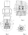
- the piezoelectric pressure sensor shown has a housing 1 which can be inserted into a measuring bore and which accommodates a piezoelectric measuring element 4 in its interior, which is arranged between a sensor membrane 5 arranged on the front or pressure side of the housing 1 and an inner housing shoulder 11a.
- the sensor membrane 5 consists essentially of the central pressure stamp 9 which is surrounded by an elastic membrane area 22 and terminates on the outside with a pot-shaped flange area 23, which is welded to the housing 1 and can accommodate a thermal protection element 24.
- the piezoelectric measuring element 4 consists of a single crystal element 6a, which is clamped with its base surface 13 and its opposite top surface 14 between the plunger 9 of the sensor membrane 5 and a discharge electrode 8 supported on the housing shoulder 11a.
- the lateral boundary surfaces i.e. a lateral surface 7a of the crystal element 6a connecting the base surface 13 to the top surface 14, for the most part (in the example shown, essentially over the entire surface) rests against a positioning sleeve 12a arranged in the housing 1.
- the positioning sleeve 12a is supported in the radial direction on an inner wall 15a of the housing 1 of the pressure sensor.
- the crystal element 6a is designed cuboid or rod-shaped using the transversal piezo effect, the greatest longitudinal extent of the crystal element 6a preferably being oriented normal to the central axis of the pressure sensor.
- the jacket surface 7a of the crystal element 6a which is composed of the longitudinal and transverse surfaces, rests essentially over the entire surface of the electrically insulating positioning sleeve 12a.
- the positioning sleeve 12a has a central area 16 with a preferably rectangular or square recess 17 for the crystal element 6a, which is adjoined at least on one side by an annular area 18 for at least partial accommodation of the discharge electrode 8 and / or the plunger 9.
- a slight axial clearance between the central area 16 of the positioning sleeve 12a and the plunger 9 or the discharge electrode 8 ensures an undisturbed introduction of force into the piezoelectric crystal element 6a.
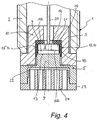
- Fig. 4 shows a pressure sensor with an outer housing 2, which accommodates a pot-shaped inner housing 10 while forming an annular gap 3, a piezoelectric measuring element 4 being prestressed against the inner pot base between the sensor membrane 5 arranged on the pressure side of the inner housing 10 and an inner pot base or inner housing shoulder 11b of the inner housing 10.
- the piezoelectric measuring element 4 consists of a single crystal element 6b, the in the illustrated embodiment, is disc-shaped and with its cylindrical or circular cylindrical jacket surface 7b rests at least for the most part on the electrically insulating positioning sleeve 12b.
- the relationship between the diameter and the thickness of the flat, disc-shaped crystal element 6b is preferably from 15: 1 to 5: 1, preferably from 12: 1 to 8: 1.
- the conductor electrode 8 can consist of a disk-shaped base body 19 resting against the positioning sleeve 12a, 12b with a central signal derivation 20, the disk-shaped base body 19 being positioned on the housing shoulder 11a of the housing 1 with a preferably circular insulating element 21 in between. Fig. 2 ) or the inner pot base or housing shoulder 11b of the inner housing 10 ( Fig. 4 ) is supported.
Landscapes
- Physics & Mathematics (AREA)
- General Physics & Mathematics (AREA)
- Chemical & Material Sciences (AREA)
- Engineering & Computer Science (AREA)
- Combustion & Propulsion (AREA)
- Analytical Chemistry (AREA)
- Measuring Fluid Pressure (AREA)
Claims (12)
- Capteur de pression piézoélectrique destiné à mesurer des hautes pressions comprenant un boîtier (1) se logeant dans un perçage de mesure ainsi qu'un élément de mesure piézoélectrique (4) placé entre une membrane de capteur (5) installée côté frontal du boîtier (1) et un épaulement intérieur de boîtier (11a, 11b),
l'élément de mesure piézoélectrique (4) étant composé d'un unique élément de cristal (6a, 6b),
capteur de pression caractérisé en ce que
l'élément de cristal (6a, 6b) est serré par sa surface de base (13) et sa surface de dessus (14) opposée, entre un poinçon (9) de la membrane de capteur (5) et une électrode de sortie (8) s'appuyant contre l'épaulement de boîtier (11a, 11b), et
une surface enveloppe (7a, 7b) de l'élément de cristal (6a, 6b) reliant la surface de base (13) à la surface supérieure (14) s'applique en grande partie contre un manchon de positionnement (12a, 12b) électro-isolant prévu dans le boîtier (1). - Capteur de pression piézoélectrique selon la revendication 1,
caractérisé en ce que
le manchon de positionnement électro-isolant (12a, 12b) s'appuie dans la direction radiale contre la paroi intérieure (15a, 15b) du boîtier (1). - Capteur de pression piézoélectrique selon la revendication 1 ou 2,
caractérisé en ce que
l'élément de cristal (6a) a une forme de parallélépipède ou de tige. - Capteur de pression piézoélectrique selon la revendication 3,
caractérisé en ce que
le manchon de positionnement (12a) a une zone centrale (16) avec un évidement (17) de forme rectangulaire ou carrée pour l'élément de cristal (6a), suivi sur au moins un côté, d'une zone (18) en forme d'anneau de cercle pour recevoir l'électrode de sortie (8) et/ou le poinçon (9). - Capteur de pression piézoélectrique selon la revendication 1 ou 2,
caractérisé en ce que
l'élément de cristal (6b) est en forme de disque. - Capteur de pression piézoélectrique selon la revendication 5,
caractérisé en ce que
le diamètre par rapport à l'épaisseur de l'élément de cristal (6b) en forme de disque est de 15:1 jusqu'à 5:1. - Capteur de pression piézoélectrique selon la revendication 6,
caractérisé en ce que
le diamètre par rapport à l'épaisseur, de l'élément de cristal en forme de disque (6b) correspond à un rapport de 12:1 jusqu'à 8:1. - Capteur de pression piézoélectrique selon l'une des revendications 1 à 7,
caractérisé en ce que
le boîtier (1) se compose d'un boîtier extérieur (2) et d'un boîtier intérieur (10) en forme de pot, logé dans celui-ci, l'élément de cristal (6a, 6b) étant prévu entre la membrane de capteur (5) sur le côté frontal du boîtier intérieur (10) et un épaulement (11b) du boîtier intérieur (10). - Capteur de pression piézoélectrique selon la revendication 8,
caractérisé en ce que
vers le boîtier extérieur (2) le boîtier intérieur (10) comporte un intervalle annulaire (3). - Capteur de pression piézoélectrique selon l'une des revendications 1 à 9,
caractérisé en ce que
l'électrode de sortie (8) a un corps de base (19) en forme de disque s'appliquant contre le manchon de positionnement (12a, 12b) et ayant une sortie centrale de signal (20), le corps de base (19) en forme de disque s'appuyant contre l'épaulement de boîtier (11a, 11b) avec interposition d'un élément isolant (21). - Capteur de pression piézoélectrique selon la revendication 10,
caractérisé en ce que
l'élément isolant (21) est en forme d'anneau de cercle. - Capteur de pression piézoélectrique selon l'une des revendications 1 à 11,
caractérisé en ce que
l'élément de cristal (6a, 6b) est la langasite, le langatate, le niobiat de lithium ou l'orthophosphate de gallium.
Applications Claiming Priority (1)
| Application Number | Priority Date | Filing Date | Title |
|---|---|---|---|
| ATA50519/2016A AT518650B1 (de) | 2016-06-07 | 2016-06-07 | Piezoelektrischer drucksensor zum messen hoher drücke |
Publications (2)
| Publication Number | Publication Date |
|---|---|
| EP3255401A1 EP3255401A1 (fr) | 2017-12-13 |
| EP3255401B1 true EP3255401B1 (fr) | 2021-03-31 |
Family
ID=58873712
Family Applications (1)
| Application Number | Title | Priority Date | Filing Date |
|---|---|---|---|
| EP17173611.9A Active EP3255401B1 (fr) | 2016-06-07 | 2017-05-31 | Capteur de pression piézoélectrique destiné à la mesure de hautes pressions |
Country Status (3)
| Country | Link |
|---|---|
| EP (1) | EP3255401B1 (fr) |
| CN (1) | CN107478380B (fr) |
| AT (1) | AT518650B1 (fr) |
Families Citing this family (2)
| Publication number | Priority date | Publication date | Assignee | Title |
|---|---|---|---|---|
| CN114526858B (zh) * | 2021-12-29 | 2023-10-20 | 浙江力夫传感技术有限公司 | 一种高可靠性压力变送器 |
| CN114486052B (zh) * | 2022-02-18 | 2023-03-21 | 中国空气动力研究与发展中心超高速空气动力研究所 | 一种外壳绝缘型压电式压力传感器 |
Citations (10)
| Publication number | Priority date | Publication date | Assignee | Title |
|---|---|---|---|---|
| GB404622A (en) | 1932-07-12 | 1934-01-12 | James Taylor | Improvements in or relating to pressure gauges |
| AT269515B (de) | 1967-02-20 | 1969-03-25 | H C Hans Dipl Ing Dr Dr List | Piezoelektrischer Meßwandler mit Beschleunigungskompensation |
| DE3828738A1 (de) | 1987-08-25 | 1989-03-09 | Ngk Spark Plug Co | Zuendkerze mit drucksensor |
| US5111699A (en) | 1990-04-05 | 1992-05-12 | Texas Instruments Incorporated | Sensor for measuring the pressure of a medium |
| EP0549346A2 (fr) | 1991-12-24 | 1993-06-30 | NGK Spark Plug Co. Ltd. | Capteur de pression de fluide piézoélectrique |
| DE102004054348A1 (de) | 2004-11-09 | 2006-05-11 | Hsb Selbstbausysteme Gmbh | Verfahren zur Herstellung eines Verbundglases und Verbundglas |
| WO2006089446A1 (fr) | 2005-02-24 | 2006-08-31 | Kistler Holding Ag | Composant pour capteurs de force ou de pression, dont les elements sont maintenus les uns avec les autres par un film electro-isolant |
| US20100294028A1 (en) | 2009-05-25 | 2010-11-25 | Siegenthaler Petra | Device for detecting a combustion chamber pressure of an internal combustion engine |
| EP3124944A1 (fr) | 2015-07-31 | 2017-02-01 | Kistler Holding AG | Capteur de pression piezoélectrique |
| EP3124943A1 (fr) | 2015-07-31 | 2017-02-01 | Kistler Holding AG | Capteur de pression piezoelectrique et procede de fabrication dudit capteur de pression piezoelectrique |
Family Cites Families (16)
| Publication number | Priority date | Publication date | Assignee | Title |
|---|---|---|---|---|
| US2894317A (en) * | 1954-06-07 | 1959-07-14 | Spence T Marks | Method for constructing a barium titanate blast velocity gauge |
| AT276810B (de) * | 1967-06-14 | 1969-12-10 | List Hans | Piezoelektrischer Meßwandler |
| CH587478A5 (fr) * | 1974-11-08 | 1977-04-29 | Kistler Instrumente Ag | |
| AT384676B (de) | 1983-07-07 | 1987-12-28 | Avl Verbrennungskraft Messtech | Messwertaufnehmer zur messung heisser medien und verfahren zur montage eines als druckaufnehmerausgebildeten messwertaufnehmers |
| US4604544A (en) * | 1983-10-17 | 1986-08-05 | Jeco Co., Ltd. | Piezoelectric pressure indicator |
| AT389170B (de) | 1987-11-19 | 1989-10-25 | Avl Verbrennungskraft Messtech | Piezoelektrisches messelement |
| AT394112B (de) * | 1989-03-30 | 1992-02-10 | Avl Verbrennungskraft Messtech | Druckaufnehmer |
| AT503816B1 (de) * | 2006-06-06 | 2008-01-15 | Piezocryst Advanced Sensorics | Piezoelektrischer sensor |
| AT504485B1 (de) | 2006-11-22 | 2008-06-15 | Piezocryst Advanced Sensorics | Piezoelektrischer drucksensor |
| AT505015B1 (de) | 2007-07-27 | 2008-10-15 | Piezocryst Advanced Sensorics | Drucksensor |
| CH705469A1 (de) | 2011-09-07 | 2013-03-15 | Kistler Holding Ag | Drucksensor mit Überlastschutz. |
| EP2827117B1 (fr) * | 2012-03-16 | 2018-12-05 | Citizen Finedevice Co., Ltd. | Moteur à combustion interne doté d'un dispositif de détection de la pression de combustion |
| WO2013147260A1 (fr) * | 2012-03-29 | 2013-10-03 | シチズンファインテックミヨタ株式会社 | Dispositif de détection de la pression, et moteur à combustion interne doté du dispositif de détection de la pression |
| JP2014070952A (ja) * | 2012-09-28 | 2014-04-21 | Citizen Finetech Miyota Co Ltd | 燃焼圧センサ |
| DE102013215860A1 (de) * | 2013-08-12 | 2015-02-12 | Robert Bosch Gmbh | Sensormodul für Druckmessglühstiftkerze |
| JP6605449B2 (ja) * | 2014-03-27 | 2019-11-13 | シチズンファインデバイス株式会社 | 燃焼圧センサ及びその製造方法 |
-
2016
- 2016-06-07 AT ATA50519/2016A patent/AT518650B1/de active
-
2017
- 2017-05-31 EP EP17173611.9A patent/EP3255401B1/fr active Active
- 2017-06-06 CN CN201710418183.2A patent/CN107478380B/zh active Active
Patent Citations (10)
| Publication number | Priority date | Publication date | Assignee | Title |
|---|---|---|---|---|
| GB404622A (en) | 1932-07-12 | 1934-01-12 | James Taylor | Improvements in or relating to pressure gauges |
| AT269515B (de) | 1967-02-20 | 1969-03-25 | H C Hans Dipl Ing Dr Dr List | Piezoelektrischer Meßwandler mit Beschleunigungskompensation |
| DE3828738A1 (de) | 1987-08-25 | 1989-03-09 | Ngk Spark Plug Co | Zuendkerze mit drucksensor |
| US5111699A (en) | 1990-04-05 | 1992-05-12 | Texas Instruments Incorporated | Sensor for measuring the pressure of a medium |
| EP0549346A2 (fr) | 1991-12-24 | 1993-06-30 | NGK Spark Plug Co. Ltd. | Capteur de pression de fluide piézoélectrique |
| DE102004054348A1 (de) | 2004-11-09 | 2006-05-11 | Hsb Selbstbausysteme Gmbh | Verfahren zur Herstellung eines Verbundglases und Verbundglas |
| WO2006089446A1 (fr) | 2005-02-24 | 2006-08-31 | Kistler Holding Ag | Composant pour capteurs de force ou de pression, dont les elements sont maintenus les uns avec les autres par un film electro-isolant |
| US20100294028A1 (en) | 2009-05-25 | 2010-11-25 | Siegenthaler Petra | Device for detecting a combustion chamber pressure of an internal combustion engine |
| EP3124944A1 (fr) | 2015-07-31 | 2017-02-01 | Kistler Holding AG | Capteur de pression piezoélectrique |
| EP3124943A1 (fr) | 2015-07-31 | 2017-02-01 | Kistler Holding AG | Capteur de pression piezoelectrique et procede de fabrication dudit capteur de pression piezoelectrique |
Non-Patent Citations (1)
| Title |
|---|
| "PIEZOELEKTRISCHE MESSTECHNIK. PHYSIKALISCHE GRUNDLAGEN, KRAFT-,DRUCK- UND BESCHLEUNIGUNGSAUFNEHMER, VERSTAERKER", 1 January 1980, article TICHY: "Piezoelektrische Messtechnik passage", pages: 1 - 47, XP055879149 |
Also Published As
| Publication number | Publication date |
|---|---|
| CN107478380B (zh) | 2021-06-29 |
| AT518650A4 (de) | 2017-12-15 |
| AT518650B1 (de) | 2017-12-15 |
| EP3255401A1 (fr) | 2017-12-13 |
| CN107478380A (zh) | 2017-12-15 |
Similar Documents
| Publication | Publication Date | Title |
|---|---|---|
| EP1082567B1 (fr) | Actionneur piezoelectrique | |
| EP2174107B1 (fr) | Capteur de pression piézoélectrique | |
| EP3255401B1 (fr) | Capteur de pression piézoélectrique destiné à la mesure de hautes pressions | |
| WO2015090757A1 (fr) | Capteur de pression | |
| EP2843385B1 (fr) | Capteur de pression | |
| EP3124943B1 (fr) | Capteur de pression piezoelectrique et procede de fabrication dudit capteur de pression piezoelectrique | |
| DE102007011283A1 (de) | Piezoelektrischer Drucksensor | |
| EP3124944B1 (fr) | Capteur de pression piezoélectrique | |
| EP1967834B1 (fr) | Bougie d'allumage avec un capteur de mesure de pression | |
| WO2005064298A2 (fr) | Capteur de pression | |
| DE102011077659A1 (de) | Keramikheizung mit Heizelement, das bei Zufuhr von Strom Wärme erzeugt | |
| EP0226742A2 (fr) | Capteur de pression pour mesurer des pressions à hautes températures | |
| DE102018113935A1 (de) | Membrandrucksensor mit Messfeder-Stützrohr und darauf beschichtetem Drucksensor | |
| EP3543671A1 (fr) | Capteur de pression | |
| EP1170578B1 (fr) | Capteur de pression résistant aux surcharges | |
| EP3285057B1 (fr) | Capteur de pression élevée | |
| EP3176555A1 (fr) | Capteur de pression piezoelectrique et son procédé de fabrication | |
| DE102006006076B4 (de) | Piezo-Aktor, Verfahren zum Herstellen eines Piezo-Aktors und Einspritzsystem mit einem solchen | |
| EP3124945B1 (fr) | Capteur de pression piezoélectrique | |
| CH709195B1 (de) | Drucksensor mit Wärmeleitelement. | |
| AT523625B1 (de) | Drucksensor | |
| DE102014105687B3 (de) | Zündkerze | |
| DE3714131C2 (fr) | ||
| DE102005062881A1 (de) | Zündkerze für eine Verbrennungskraftmaschine | |
| DE102016121346A1 (de) | Glühkerze |
Legal Events
| Date | Code | Title | Description |
|---|---|---|---|
| PUAI | Public reference made under article 153(3) epc to a published international application that has entered the european phase |
Free format text: ORIGINAL CODE: 0009012 |
|
| STAA | Information on the status of an ep patent application or granted ep patent |
Free format text: STATUS: THE APPLICATION HAS BEEN PUBLISHED |
|
| AK | Designated contracting states |
Kind code of ref document: A1 Designated state(s): AL AT BE BG CH CY CZ DE DK EE ES FI FR GB GR HR HU IE IS IT LI LT LU LV MC MK MT NL NO PL PT RO RS SE SI SK SM TR |
|
| AX | Request for extension of the european patent |
Extension state: BA ME |
|
| STAA | Information on the status of an ep patent application or granted ep patent |
Free format text: STATUS: REQUEST FOR EXAMINATION WAS MADE |
|
| 17P | Request for examination filed |
Effective date: 20180613 |
|
| RBV | Designated contracting states (corrected) |
Designated state(s): AL AT BE BG CH CY CZ DE DK EE ES FI FR GB GR HR HU IE IS IT LI LT LU LV MC MK MT NL NO PL PT RO RS SE SI SK SM TR |
|
| STAA | Information on the status of an ep patent application or granted ep patent |
Free format text: STATUS: EXAMINATION IS IN PROGRESS |
|
| 17Q | First examination report despatched |
Effective date: 20190522 |
|
| GRAP | Despatch of communication of intention to grant a patent |
Free format text: ORIGINAL CODE: EPIDOSNIGR1 |
|
| STAA | Information on the status of an ep patent application or granted ep patent |
Free format text: STATUS: GRANT OF PATENT IS INTENDED |
|
| INTG | Intention to grant announced |
Effective date: 20201210 |
|
| GRAS | Grant fee paid |
Free format text: ORIGINAL CODE: EPIDOSNIGR3 |
|
| GRAA | (expected) grant |
Free format text: ORIGINAL CODE: 0009210 |
|
| STAA | Information on the status of an ep patent application or granted ep patent |
Free format text: STATUS: THE PATENT HAS BEEN GRANTED |
|
| AK | Designated contracting states |
Kind code of ref document: B1 Designated state(s): AL AT BE BG CH CY CZ DE DK EE ES FI FR GB GR HR HU IE IS IT LI LT LU LV MC MK MT NL NO PL PT RO RS SE SI SK SM TR |
|
| REG | Reference to a national code |
Ref country code: GB Ref legal event code: FG4D Free format text: NOT ENGLISH Ref country code: CH Ref legal event code: EP |
|
| REG | Reference to a national code |
Ref country code: DE Ref legal event code: R096 Ref document number: 502017009860 Country of ref document: DE Ref country code: AT Ref legal event code: REF Ref document number: 1377463 Country of ref document: AT Kind code of ref document: T Effective date: 20210415 |
|
| REG | Reference to a national code |
Ref country code: IE Ref legal event code: FG4D Free format text: LANGUAGE OF EP DOCUMENT: GERMAN |
|
| REG | Reference to a national code |
Ref country code: LT Ref legal event code: MG9D |
|
| PG25 | Lapsed in a contracting state [announced via postgrant information from national office to epo] |
Ref country code: NO Free format text: LAPSE BECAUSE OF FAILURE TO SUBMIT A TRANSLATION OF THE DESCRIPTION OR TO PAY THE FEE WITHIN THE PRESCRIBED TIME-LIMIT Effective date: 20210630 Ref country code: FI Free format text: LAPSE BECAUSE OF FAILURE TO SUBMIT A TRANSLATION OF THE DESCRIPTION OR TO PAY THE FEE WITHIN THE PRESCRIBED TIME-LIMIT Effective date: 20210331 Ref country code: HR Free format text: LAPSE BECAUSE OF FAILURE TO SUBMIT A TRANSLATION OF THE DESCRIPTION OR TO PAY THE FEE WITHIN THE PRESCRIBED TIME-LIMIT Effective date: 20210331 Ref country code: BG Free format text: LAPSE BECAUSE OF FAILURE TO SUBMIT A TRANSLATION OF THE DESCRIPTION OR TO PAY THE FEE WITHIN THE PRESCRIBED TIME-LIMIT Effective date: 20210630 |
|
| PG25 | Lapsed in a contracting state [announced via postgrant information from national office to epo] |
Ref country code: SE Free format text: LAPSE BECAUSE OF FAILURE TO SUBMIT A TRANSLATION OF THE DESCRIPTION OR TO PAY THE FEE WITHIN THE PRESCRIBED TIME-LIMIT Effective date: 20210331 Ref country code: RS Free format text: LAPSE BECAUSE OF FAILURE TO SUBMIT A TRANSLATION OF THE DESCRIPTION OR TO PAY THE FEE WITHIN THE PRESCRIBED TIME-LIMIT Effective date: 20210331 Ref country code: LV Free format text: LAPSE BECAUSE OF FAILURE TO SUBMIT A TRANSLATION OF THE DESCRIPTION OR TO PAY THE FEE WITHIN THE PRESCRIBED TIME-LIMIT Effective date: 20210331 |
|
| REG | Reference to a national code |
Ref country code: NL Ref legal event code: MP Effective date: 20210331 |
|
| PG25 | Lapsed in a contracting state [announced via postgrant information from national office to epo] |
Ref country code: NL Free format text: LAPSE BECAUSE OF FAILURE TO SUBMIT A TRANSLATION OF THE DESCRIPTION OR TO PAY THE FEE WITHIN THE PRESCRIBED TIME-LIMIT Effective date: 20210331 Ref country code: SM Free format text: LAPSE BECAUSE OF FAILURE TO SUBMIT A TRANSLATION OF THE DESCRIPTION OR TO PAY THE FEE WITHIN THE PRESCRIBED TIME-LIMIT Effective date: 20210331 Ref country code: CZ Free format text: LAPSE BECAUSE OF FAILURE TO SUBMIT A TRANSLATION OF THE DESCRIPTION OR TO PAY THE FEE WITHIN THE PRESCRIBED TIME-LIMIT Effective date: 20210331 Ref country code: EE Free format text: LAPSE BECAUSE OF FAILURE TO SUBMIT A TRANSLATION OF THE DESCRIPTION OR TO PAY THE FEE WITHIN THE PRESCRIBED TIME-LIMIT Effective date: 20210331 Ref country code: LT Free format text: LAPSE BECAUSE OF FAILURE TO SUBMIT A TRANSLATION OF THE DESCRIPTION OR TO PAY THE FEE WITHIN THE PRESCRIBED TIME-LIMIT Effective date: 20210331 |
|
| PG25 | Lapsed in a contracting state [announced via postgrant information from national office to epo] |
Ref country code: IS Free format text: LAPSE BECAUSE OF FAILURE TO SUBMIT A TRANSLATION OF THE DESCRIPTION OR TO PAY THE FEE WITHIN THE PRESCRIBED TIME-LIMIT Effective date: 20210731 Ref country code: PL Free format text: LAPSE BECAUSE OF FAILURE TO SUBMIT A TRANSLATION OF THE DESCRIPTION OR TO PAY THE FEE WITHIN THE PRESCRIBED TIME-LIMIT Effective date: 20210331 Ref country code: PT Free format text: LAPSE BECAUSE OF FAILURE TO SUBMIT A TRANSLATION OF THE DESCRIPTION OR TO PAY THE FEE WITHIN THE PRESCRIBED TIME-LIMIT Effective date: 20210802 Ref country code: RO Free format text: LAPSE BECAUSE OF FAILURE TO SUBMIT A TRANSLATION OF THE DESCRIPTION OR TO PAY THE FEE WITHIN THE PRESCRIBED TIME-LIMIT Effective date: 20210331 Ref country code: SK Free format text: LAPSE BECAUSE OF FAILURE TO SUBMIT A TRANSLATION OF THE DESCRIPTION OR TO PAY THE FEE WITHIN THE PRESCRIBED TIME-LIMIT Effective date: 20210331 |
|
| REG | Reference to a national code |
Ref country code: DE Ref legal event code: R026 Ref document number: 502017009860 Country of ref document: DE |
|
| PLBI | Opposition filed |
Free format text: ORIGINAL CODE: 0009260 |
|
| PLAX | Notice of opposition and request to file observation + time limit sent |
Free format text: ORIGINAL CODE: EPIDOSNOBS2 |
|
| PG25 | Lapsed in a contracting state [announced via postgrant information from national office to epo] |
Ref country code: ES Free format text: LAPSE BECAUSE OF FAILURE TO SUBMIT A TRANSLATION OF THE DESCRIPTION OR TO PAY THE FEE WITHIN THE PRESCRIBED TIME-LIMIT Effective date: 20210331 Ref country code: DK Free format text: LAPSE BECAUSE OF FAILURE TO SUBMIT A TRANSLATION OF THE DESCRIPTION OR TO PAY THE FEE WITHIN THE PRESCRIBED TIME-LIMIT Effective date: 20210331 Ref country code: AL Free format text: LAPSE BECAUSE OF FAILURE TO SUBMIT A TRANSLATION OF THE DESCRIPTION OR TO PAY THE FEE WITHIN THE PRESCRIBED TIME-LIMIT Effective date: 20210331 Ref country code: LU Free format text: LAPSE BECAUSE OF NON-PAYMENT OF DUE FEES Effective date: 20210531 Ref country code: MC Free format text: LAPSE BECAUSE OF FAILURE TO SUBMIT A TRANSLATION OF THE DESCRIPTION OR TO PAY THE FEE WITHIN THE PRESCRIBED TIME-LIMIT Effective date: 20210331 |
|
| 26 | Opposition filed |
Opponent name: KISTLER INSTRUMENTE AG Effective date: 20211222 |
|
| REG | Reference to a national code |
Ref country code: BE Ref legal event code: MM Effective date: 20210531 |
|
| PG25 | Lapsed in a contracting state [announced via postgrant information from national office to epo] |
Ref country code: IE Free format text: LAPSE BECAUSE OF NON-PAYMENT OF DUE FEES Effective date: 20210531 |
|
| PLBB | Reply of patent proprietor to notice(s) of opposition received |
Free format text: ORIGINAL CODE: EPIDOSNOBS3 |
|
| PG25 | Lapsed in a contracting state [announced via postgrant information from national office to epo] |
Ref country code: IS Free format text: LAPSE BECAUSE OF FAILURE TO SUBMIT A TRANSLATION OF THE DESCRIPTION OR TO PAY THE FEE WITHIN THE PRESCRIBED TIME-LIMIT Effective date: 20210731 |
|
| PG25 | Lapsed in a contracting state [announced via postgrant information from national office to epo] |
Ref country code: BE Free format text: LAPSE BECAUSE OF NON-PAYMENT OF DUE FEES Effective date: 20210531 |
|
| PG25 | Lapsed in a contracting state [announced via postgrant information from national office to epo] |
Ref country code: HU Free format text: LAPSE BECAUSE OF FAILURE TO SUBMIT A TRANSLATION OF THE DESCRIPTION OR TO PAY THE FEE WITHIN THE PRESCRIBED TIME-LIMIT; INVALID AB INITIO Effective date: 20170531 |
|
| P01 | Opt-out of the competence of the unified patent court (upc) registered |
Effective date: 20230502 |
|
| PG25 | Lapsed in a contracting state [announced via postgrant information from national office to epo] |
Ref country code: CY Free format text: LAPSE BECAUSE OF FAILURE TO SUBMIT A TRANSLATION OF THE DESCRIPTION OR TO PAY THE FEE WITHIN THE PRESCRIBED TIME-LIMIT Effective date: 20210331 |
|
| REG | Reference to a national code |
Ref country code: AT Ref legal event code: MM01 Ref document number: 1377463 Country of ref document: AT Kind code of ref document: T Effective date: 20220531 |
|
| PG25 | Lapsed in a contracting state [announced via postgrant information from national office to epo] |
Ref country code: GR Free format text: LAPSE BECAUSE OF FAILURE TO SUBMIT A TRANSLATION OF THE DESCRIPTION OR TO PAY THE FEE WITHIN THE PRESCRIBED TIME-LIMIT Effective date: 20210331 Ref country code: AT Free format text: LAPSE BECAUSE OF NON-PAYMENT OF DUE FEES Effective date: 20220531 |
|
| PGFP | Annual fee paid to national office [announced via postgrant information from national office to epo] |
Ref country code: IT Payment date: 20230525 Year of fee payment: 7 Ref country code: FR Payment date: 20230523 Year of fee payment: 7 Ref country code: DE Payment date: 20230530 Year of fee payment: 7 Ref country code: CH Payment date: 20230602 Year of fee payment: 7 |
|
| PGFP | Annual fee paid to national office [announced via postgrant information from national office to epo] |
Ref country code: GB Payment date: 20230523 Year of fee payment: 7 |
|
| APBM | Appeal reference recorded |
Free format text: ORIGINAL CODE: EPIDOSNREFNO |
|
| APBP | Date of receipt of notice of appeal recorded |
Free format text: ORIGINAL CODE: EPIDOSNNOA2O |
|
| APAH | Appeal reference modified |
Free format text: ORIGINAL CODE: EPIDOSCREFNO |
|
| APBQ | Date of receipt of statement of grounds of appeal recorded |
Free format text: ORIGINAL CODE: EPIDOSNNOA3O |
|
| PG25 | Lapsed in a contracting state [announced via postgrant information from national office to epo] |
Ref country code: MK Free format text: LAPSE BECAUSE OF FAILURE TO SUBMIT A TRANSLATION OF THE DESCRIPTION OR TO PAY THE FEE WITHIN THE PRESCRIBED TIME-LIMIT Effective date: 20210331 |