EP3255208B1 - Modulare paneele zur herstellung eines installierbaren/entfernbaren temporären bodens und verfahren zur herstellung dieses bodens - Google Patents
Modulare paneele zur herstellung eines installierbaren/entfernbaren temporären bodens und verfahren zur herstellung dieses bodens Download PDFInfo
- Publication number
- EP3255208B1 EP3255208B1 EP17175384.1A EP17175384A EP3255208B1 EP 3255208 B1 EP3255208 B1 EP 3255208B1 EP 17175384 A EP17175384 A EP 17175384A EP 3255208 B1 EP3255208 B1 EP 3255208B1
- Authority
- EP
- European Patent Office
- Prior art keywords
- connecting plate
- rectangular
- floor
- designed
- panels
- Prior art date
- Legal status (The legal status is an assumption and is not a legal conclusion. Google has not performed a legal analysis and makes no representation as to the accuracy of the status listed.)
- Not-in-force
Links
Images


Classifications
-
- E—FIXED CONSTRUCTIONS
- E04—BUILDING
- E04F—FINISHING WORK ON BUILDINGS, e.g. STAIRS, FLOORS
- E04F15/00—Flooring
- E04F15/02—Flooring or floor layers composed of a number of similar elements
- E04F15/024—Sectional false floors, e.g. computer floors
- E04F15/02405—Floor panels
-
- E—FIXED CONSTRUCTIONS
- E01—CONSTRUCTION OF ROADS, RAILWAYS, OR BRIDGES
- E01C—CONSTRUCTION OF, OR SURFACES FOR, ROADS, SPORTS GROUNDS, OR THE LIKE; MACHINES OR AUXILIARY TOOLS FOR CONSTRUCTION OR REPAIR
- E01C5/00—Pavings made of prefabricated single units
- E01C5/005—Individual couplings or spacer elements for joining the prefabricated units
-
- E—FIXED CONSTRUCTIONS
- E01—CONSTRUCTION OF ROADS, RAILWAYS, OR BRIDGES
- E01C—CONSTRUCTION OF, OR SURFACES FOR, ROADS, SPORTS GROUNDS, OR THE LIKE; MACHINES OR AUXILIARY TOOLS FOR CONSTRUCTION OR REPAIR
- E01C9/00—Special pavings; Pavings for special parts of roads or airfields
- E01C9/08—Temporary pavings
- E01C9/086—Temporary pavings made of concrete, wood, bitumen, rubber or synthetic material or a combination thereof
Definitions
- the present patent application relates to modular panels for making an installable/removable temporary floor and a method for making said floor.
- the present invention relates to modular panels, which are designed to be arranged in adjacent positions, connected to each other, to form a temporary floor for protecting and covering a surface of an indoor or outdoor area/space intended, for example, to host an event, such as a sport, artistic or music event (a concert), or another similar event/occasion; the following presentation will make explicit reference to this without losing in general information.
- an event such as a sport, artistic or music event (a concert), or another similar event/occasion; the following presentation will make explicit reference to this without losing in general information.
- This type of floor is generally installable/removable and is provided with a plurality of modular panels that can be connected to each other to form a walkable floor, which covers the surface to be protected.
- the panels In use, before the event, the panels are positioned resting on the surface, side by side, touching each other, and they are jointly connected so that they can be dismantled after the event to free the surface below.
- Patent EP 0 861 351 B1 describes a floor, for example, provided with flat, reinforcing panels for the ground, wherein a pair of parallel rectilinear edges of each panel are fitted, one with built-in female locking elements and, the other with corresponding male locking elements, protruding in the plane of the panel, to engage removably, in a vertical direction to the plane of the panel, with the female locking elements of an adjacent panel, so that they cannot be disengaged from the female locking elements in the horizontal plane of the panel.
- the first male and female locking elements of the panel are made in the form of prismatic pins provided with wings, and the second from corresponding prismatic recesses. They are made so that, when engaged, they make a limited relative rotation about an axis parallel to the adjacent sides of the panels, in such a way that they are hinged in an interlocking manner.
- the previously described panels are advantageous as they create a temporary floor that adapts to the changing inclinations of the resting surface and they can be assembled/dismantled quickly and cheaply, on the axis parallel to the adjacent sides of the panels, in such a way that they are hinged in an interlocking manner.
- the previously described panels are advantageous as they create a temporary floor that adapts to the changing inclinations of the resting surface and they can be assembled/dismantled quickly and cheaply, on the other, they present the technical problem of the protruding prismatic pins being subject to breakage/damage. Naturally, when a single prismatic pin of a panel is damaged, the use of the whole panel is compromised, with consequent replacement and disposal costs.
- DE 196 00 318 C1 discloses a floor plate having over its circumference recesses which take connectors fitted from above to couple other plates;
- DE 203 02 434 U1 discloses garden path component made up of several panels held together by connectors;
- US2013/167458 A1 discloses a modular flooring system including a plurality of floor tiles and connection interfaces with opposing engagement surfaces;
- US2005/241243 discloses an assembly of modular resin components including separate base plates for the components;
- US 5971655A discloses a connection structure of deckings including an upward hook and a receptacle wherein the upward hook is inserted into the receptacle.
- the Applicant has carried out an in-depth study aimed at identifying a solution, which, on the one hand, preserves the advantages of the previously described panels, in other words their elevated adaptability to the resting surface and easy assembly/dismantling, while, on the other, overcoming the technical problem of said panels.
- an installable/removable temporary floor (in other words of the type that is easy to remove), which can be walked on (shown only partially) and preferably used for sports events, music events or other similar events/occasions that is designed to be arranged on a surface S to be protected so that it is temporarily covered/faced, is globally indicated with number 1.
- the floor 1 is designed to be installed/assembled, before the event, resting on the surface S (ground) so that it covers/faces the surface S and protects it from being walked on and then it is dismantled after the event, to free/uncover the previously covered surface S.
- the floor 1 can preferably be used to protect, for example, a surface in a sports stadium (not illustrated), such as, for example, a surface S covered with grass, or a wooden parquet floor, or any other similar surface, which requires temporary protection during an event and/or is not suitable, in terms of safety, for being walked on by a considerable/significant number of people.
- a surface in a sports stadium such as, for example, a surface S covered with grass, or a wooden parquet floor, or any other similar surface, which requires temporary protection during an event and/or is not suitable, in terms of safety, for being walked on by a considerable/significant number of people.
- the floor 1, the subject of the present invention is not limited to being specifically used for events, but it can be applied to other situations, where it is necessary to cover a surface temporarily to protect it from being walked on or from other elements associated with the surface, such as, for example, irrigation systems and/or heating systems immediately below the surface.
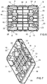
- the floor 1 comprises a plurality of tiles or panels 2, square or rectangular, which are arranged side by side, in positions adjacent to and substantially coplanar with one another, in other words resting on corresponding sides of adjacent panels 2, provided with at least one recess 3, on each of the four sides, which defines, with a corresponding recess 3 made in one side of an adjacent panel 2, a seat 4.
- the floor 1 also comprises a plurality of connecting plates 5, each of which is designed to be coupled, in a stable, but easily removable manner, to a relative seat 4, which is preferably rectangular, to make the joint connection between the two adjacent panels 2 in order to create the floor 1.
- each panel 2 is substantially planar, square or rectangular and has a plate-like body 6, whose flat upper surface defines (with the other panels) the upper walkable floor of the floor 1 and an external perimeter frame 7, which overhangs the external perimeter edge of the plate-like body 6 in a preferably orthogonal direction to the plane where the plate-like body lies and is designed, in use, for being positioned resting on the surface S to be covered/protected.
- each panel 1 preferably has two recesses 3 on each of the four sides, which are spaced apart along the common side of a set distance D.
- the panel 2 is square, as shown in the example in Figures 1 and 2 , the pairs of recesses 3 made on the four sides preferably have the same joint distance D. In this way, when two panels 2 are aligned and positioned side by side, during assembly, the pair of recesses 3 on one side of a panel 2 conveniently auto-align with the pair of recesses 3 on any one of the four sides of an adjacent panel 2, forming the relative seats 4 without the panels 2 needing to be in any particular direction, thus simplifying their assembly.
- connecting plates 5 are engaged "vertically" in relation to a lying plane of the floor 1, which, in use, is substantially horizontal as it generally corresponds to the resting surface S.
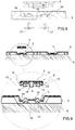
- the connecting plates 5 are rectangular and designed to be engaged manually, in a stable, but easily removable manner (as shown in Figures 8-12 and as subsequently described in detail), in the relative rectangular seats 4 along a direction A, which is substantially orthogonal to the plane on which the plate-like body 6 lies; they are provided with snap coupling members 8, which are designed, in turn, to be operated, during engagement, to make a snap coupling between the connecting plate 5 and the two adjacent panels 2, which are provided with recesses 3 forming the seat 4, to make the coupling between said panels 2.
- each connecting plate 5 comprises a rectangular-shaped flat sheet 9, which, in use, in other words after the coupling of the connecting plate 5 in the recess 3, lies on the same lying plane as the plate-like body 6 of the panel 2 so that the upper surface of the connecting plate 5 is substantially coplanar with the upper surface of the panel 2 forming the walkable surface of the floor 1.
- Each connecting plate 5 also comprises an external perimeter frame 10, which surrounds the external perimeter edge of the sheet 9 and overhangs the lower surface of the latter so that it is positioned substantially orthogonal to the sheet and preferably the reinforcing safety edges, which extend orthogonally to the sheet 9 and develop in preferably parallel and/or orthogonal directions to the L axis.
- the perimeter frame 10 of the connecting plate 5, in use, is substantially arranged close to the walls 11 (vertical in Figure 2 ) of the recesses 3 that laterally delimit the rectangular seat 4, with the lower edge/corner resting/abutting on the bottom wall 12 of the recesses 3 forming the seat 4.
- the snap coupling members 8 of each rectangular connecting plate 5 comprise two pairs of lateral teeth 13 that protrude from the outer surfaces of two parallel sides of the perimeter frame 10 of the connecting plate 5, and which are designed, in use, for snap coupling to two corresponding pairs of openings 14 made on the parallel walls 11 of the seats 4 ( Figure 2 ).
- the two pairs of teeth 13 are positioned on the respective larger sides opposite the connecting plate 5 specularly / symmetrically to each other in relation to the longitudinal axis L, so that each tooth 13 on a larger side is aligned with an opposite tooth 13 on the other larger side, along a common axis orthogonal to the L axis.
- the two teeth 13 on each larger side of the connecting plate 5 are positioned approximately at the longitudinal ends opposite the connecting plate 5, so that the opposite and aligned pairs of teeth 13 on the ends engage in the respective pairs of openings 14 in the relative two recesses 3, arranged side by side, forming the seat 4.
- each seat 4 comprises two pairs of openings 14, which are each made on a relative recess 3 to house the opposite, aligned teeth 13 on the end of the connecting plate 5.
- the internal walls 11 of each recess 3 preferably have an internal portion, which, in use, is orthogonal to the L axis of the connecting plate 5 and two lateral portions parallel to the L axis, facing each other, where the two openings 14 that house the teeth 13 are made.
- the teeth 13 can have an orthogonal section in relation to about the triangular L axis.
- a through eyelet or slot 15 can be made on the upper sheet 9, next to each tooth 13, i.e. on the perimeter edge that extends straight, preferably parallel, to the L axis and which is dimensioned in such a way that, in use, during engagement, the portion of perimeter frame supporting the tooth 13 bends elastically towards the inside of the connecting plate 5 under the pressure of the tooth 13 and then returns elastically to the initial position when the tooth 13 engages in the opening 14.
- the four slots 15 conveniently define four respective flexible wings on the perimeter frame 10, which support the teeth 13 and allow the teeth to make a limited movement (by a few millimetres) transversal to the L axis that causes the engagement in the corresponding opening 14.
- slots 15 can be made, alternatively, or in addition, on the plate-like body 6 immediately above the openings 14. In this case, during engagement, the portion of wall 11 next to the slots 15 above the opening 14 tends to flex under the pressure of the tooth 13 further assisting its engagement in the opening 14.
- the recesses 3 are provided on the outer perimeter edge of the panel 2 and are provided with circular through openings made on the bottom walls 12 of the recesses 3, to be engaged by corresponding stems or hubs 18 of the connecting plates 5.
- the circular through openings 16 and the corresponding hubs 18 are preferably designed for being engaged, in turn, by corresponding clamping screws 17 (shown in Figures 8 , 11 and 12 ), which create a stable and substantially rigid fixing of the connecting plates 5 to the panels 2.
- the connecting plate 5 comprises two hubs 18, which overhang the lower surface of the sheet 9 along relative axes orthogonal to the sheet so as to position, in use, the corresponding free ends resting/abutting on corresponding collars 19 on the bottom wall 12 of the recesses 3.
- the two hubs 18 of the connecting plate 5 are arranged parallel to each other, at a set distance from each other, so that they lie on a parallel plane to the L axis, while each collar 19 is arranged on the bottom wall 12 of the recess 3, in a coaxial position with the circular opening 16, so that it can be crossed, in use, by the stem of the clamping screw 17.
- the collar 19 can also preferably have a substantially self-centring tapered shape designed to favour the positioning of the hub 18 in the central concavity of the collar 19 so as to make the connecting plate 5 adopt the correct engagement position in the recess 3 and, at the same time, align the internal passage, preferably, but not necessarily threaded, of the hub 18 with the circular opening 16.
- the connecting plates 5 and the recesses 3 are also provided with stop members 20, which are designed to prevent the connecting plate 5, when engaged in the recesses 3, from moving inside the seat 4 along a direction parallel to the longitudinal axis L.
- the stop members 20 can comprise two pairs of protruding elements, in other words teeth 23, preferably rectangular, which are positioned on the connecting plate 5, preferably at respective longitudinal ends opposite the connecting plate 5, i.e. next to the two smaller sides of the plate, and are designed, in use, for abutting on a respective pair of shoulders 24 (shown in Figures 1 and 2 ) positioned on the bottom wall 12 of the recess 3.
- each shoulder 24 can comprise, for example, a substantially T-shaped profile, which has a smaller plate-like portion. Resting on this, in use, is a supporting face of a tooth 23 of the plate-like body 6 and a larger plate-like portion, which extends centrally from the relative smaller plate-like portion along a direction orthogonal to the same, designed for reinforcing the shoulder 24.
- the smaller plate-like portions of the two shoulders 24 in the recess 3 can lie on a same plane, which is preferably parallel to the internal portion of the walls 11 delimiting the recess 3 so that they are positioned, in use, abutting on the internal faces of the teeth 23.
- the connecting plate 5 and the recesses 3 can preferably be dimensioned in such a way that the width of the recess 3, measured along a direction orthogonal to the L axis, rounds up the width of the connecting plate 5, measured along a direction orthogonal to the L axis, and that the overall length of two recesses 3, arranged side by side, measured along a direction parallel to the L axis, rounds up the length of the connecting plate 5, measured along a direction parallel to the L axis.
- the two openings 14 of the recess 3 designed to house the teeth 13 are made on the two relative walls 11 of the recess 3, which extend parallel to each other, and to the longitudinal axis L of the plate 5, in symmetrical positions in relation to the middle plane of the recess 3 so that they are facing each other.
- the openings 14 have a substantially rectangular shape and a height measured along a direction orthogonal to the bottom wall 12, which is greater than the height of the tooth 13 measured along a direction orthogonal to the sheet 9.
- the tooth 13 can make millimetric vertical movements, orthogonal in relation to the bottom wall 12 of the recess 3, inside the opening 14 while remaining trapped inside the opening.
- Each opening 14 preferably has a width measured along a direction parallel to the L axis that is greater than the thickness of the tooth 13 measured along the same direction. In this way, the tooth 13 can make millimetric longitudinal movements inside the opening 14 while staying trapped inside the opening.
- the openings 14 can also preferably have rounded upper vertices, opposite the bottom wall, to facilitate the disengagement of the teeth 13 from the openings 14.
- the panels 2 and the connecting plates 5 can preferably be made of a plastic material by means of injection moulding, thermoforming or a similar process.
- the panels 2 and the connecting plates 5 can preferably be made, for example, of copolymer polypropylene.
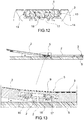
- the method comprises the steps of arranging at least one pair of panels 2, resting on the surface S (horizontal in Figure 8 ), in such a way as to position the side of an adjacent panel 2, which is preferably resting/abutted on/against the side of the other panel 2, bringing the recesses 3 together and making the seat 4; positioning the connecting plate 5 above the seat 4 made up of the two adjacent recesses 3, preferably keeping the connecting plate 5 on a plane almost parallel to the panels 2; moving the connecting plate 4, preferably keeping it on the plane parallel to the panels 2, along a direction A, which is substantially orthogonal to the panels 2, so that the hubs 18 are resting on the collars 19 and, at the same time, the two pairs of teeth 13 engage in the corresponding pairs of openings 14 in the two adjacent recesses 4 ( Figure 12 ).
- the teeth 13 bend slightly towards the inside of the connecting plate 5 thanks to the portions of wings in the frame 10 and snap couple in the respective openings 14 consequently making the connection between the two panels 2.
- the teeth 23 of the connecting plate 5 are arranged abutting on the shoulders 24, contrasting their longitudinal movement.
- the method also comprises the step of engaging the stem of the clamping screws 17 in the circular openings 16 in the bottom wall 12 of the recesses 3, and screwing the screws in the internal passages of the hubs 18, to fix the connecting plate 5 stably to the two panels 2, making the stable connection between said panels.
- the connecting plate 5 can be moved longitudinally until the teeth 23 are positioned abutting on the shoulders 24 and can, therefore, rotate partially about the axis, passing through the two aligned teeth 23.
- the connecting plate 5 allows the panels 2 to be inclined in relation to each other by a maximum set angle ⁇ without the plate 5 disengaging 5 from the seat.
- the set angle of inclination ⁇ of the adjacent panels 2 can preferably be comprised between about 7° and about 12°, preferably 10°. Thanks to this, the floor 1 can conveniently adapt to irregular surface profiles.
- the method can also comprise the steps of: making modular planar pre-assemblies 30, before laying the floor 1 on the surface S, (one of which is shown at the top, on the left in Figure 19 ), each comprising a plurality of panels 2, preferably eight panels 2, arranged on two parallel rows connected by four panels 2, each forming a rectangular walkable floor, and a plurality of first internal connecting plates, indicated by number 5' in Figure 19 , which stably fix the facing/connected sides of the panels 2, forming the modular planar pre-assembly 30, with clamping screws 17, and a series of second connecting plates, indicated by number 5" in Figure 19 , which are engaged and fixed stably with the clamping screws 17, in the recesses 3, on a larger external side and on a smaller external side of the pre-assembly.
- the two remaining larger and smaller sides of the pre-assembly 30 having recesses 3 free of plates.
- the method also comprises the step of juxtaposing the side of a modular planar pre-assembly 30, which has the second connecting plates 5" with the side of an adjacent modular planar pre-assembly 30 having free recesses 3 so as to snap couple the free ends of the second connecting plates 5" in the recesses, without screwing the clamping screws 17 in the portions of said plates, which engage in the recesses 3.
- the second connecting plates 5" can preferably be made so that they differ visually during the operations of dismantling.
- the second connecting plates 5" can be made with a surface finishing (for example smooth or with elevations) and/or a colour (for example red) different to the finishing and/or colour respectively of the first connecting plates 5'.
- the previously described floor makes it possible, on the one hand, to increase the speed of assembling/dismantling the panels, with a consequent reduction in costs and, on the other, to significantly limit the costs associated with maintaining/disposing of the panels in the event of breakage, as they are substantially limited to replacing the connecting plates, and do not require the replacement of the whole panel, as is the case with the currently adopted solutions.
- the embodiment illustrated in Figures 14 to 18 relates to a connecting plate 40, which is similar to the connecting plate 5 shown in Figures 3 to 7 , whose portions/components are distinguished, where possible, by the same reference numbers that distinguish corresponding portions/components of the connecting plate 5 described above.
- the connecting plate 40 differs from the connecting plate 5 in that the plate-like body 6 is subdivided into two substantially identical, rectangular semi-portions 6a and 6b, which are connected centrally, i.e.
- the central fold portion 41 can preferably have a thin strip of deformable/bendable material, which extends almost parallel to the upper surface of the two portions 6a and 6b along a substantially orthogonal direction to the longitudinal axis L. It is understood that the floor 1 and/or modular planar pre-assemblies 30 can comprise one or more connecting plates 5 and/or, in addition or alternatively, one or more connecting plates 40.
Landscapes
- Engineering & Computer Science (AREA)
- Architecture (AREA)
- Civil Engineering (AREA)
- Structural Engineering (AREA)
- General Engineering & Computer Science (AREA)
- Floor Finish (AREA)
- Road Paving Structures (AREA)
Claims (15)
- Installierbarer, temporärer modularer Boden (1), der ausgebildet ist, auf einer zu schützenden Fläche (S) ruhend angeordnet zu sein, sodass er die Fläche temporär abdeckt/verkleidet,
wobei der Boden (1) umfasst:mindestens zwei quadratische oder rechteckige Paneele (2), die nebeneinander in benachbarten Positionen und im Wesentlichen koplanar zueinander angeordnet sind und an jeder der vier Seiten mitmindestens einer Ausnehmung (3) versehen sind, die
einen Sitz (4) mit einer entsprechenden Ausnehmung (3), die auf einer Seite eines benachbarten Paneels (2) vorgenommen ist, definiert,mindestens eine Verbindungsplatte (5), die ausgebildet ist, in den Sitz (4) eingesetzt zu werden, um die Paneele (2) gegenseitig zu koppeln,wobei die Verbindungsplatte (5) so geformt ist, um manuell in stabiler, aber leicht entfernbarer Weise in den Sitz (4), entlang einer Richtung (A), die im Wesentlichen orthogonal zu der Ebene ist, auf der die Paneele (2) liegen eingesetzt zu werden, und mit Schnappkopplungselementen (8) versehen ist, die so ausgebildet sind, während des Eingriffs betätigt zu werden, um eine Schnappkopplung zwischen der Verbindungsplatte (5) und den Paneelen (2) herzustellen,wobei der Boden dadurch gekennzeichnet ist, dass die Verbindungsplatte (5) umfasst:eine rechteckig geformte flache Lage (9), die auf derselben Liegeebene wie das Panel (2) liegt, sodass die obere Fläche der Verbindungsplatte (5) im Wesentlichen koplanar mit der oberen Fläche des Panels (2) ist,und dabei die begehbare Fläche des Bodens (1) bildet,ein äußerer rechteckiger Umlaufrahmen (10), der eine äußere Umlaufkante der rechteckig geformten flachen Lage (9) umgibt und über eine untere Fläche der Lage hängt, so dass er im Wesentlichen orthogonal zu der rechteckig geformten flachen Lage (9) positioniert ist und im Wesentliche nahe der Wände (11) der Ausnehmungen angeordnet ist, die den rechtwinkligen Sitz (4) seitlich begrenzen, wobei eine untere Kante auf einer Bodenwand (12) der Ausnehmungen ruht/daran angrenzt, die den Sitz (4) bilden,wobei die Schnappkopplungselemente (8) zwei seitliche Zahnpaare (13) umfassen, die von äußeren Flächen zweier paralleler Seiten des äußerem rechteckigen Umlaufrahmens (10) der Verbindungsplatte (5) vorstehen, und für eine Schnappkopplung an zwei entsprechenden Öffnungspaaren (14) ausgebildet sind, die auf den parallelen Wänden (11) der Sitze (4) gebildet sind,wobei die zwei Zahnpaare (13) auf den jeweils größeren Seiten gegenüber der Verbindungsplatte (5) positioniert sind, symmetrisch zueinander im Verhältnis zur Längsachse (L) der Verbindungsplatte (5), sodass jeder Zahn (13) an einer größeren Seite mit einem gegenüberliegenden Zahn (13) auf der anderen größeren Seite ausgerichtet ist, entlang einer gemeinsamen Achse orthogonal zur Längsachse (L). - Boden nach Anspruch 1, wobei die Verbindungsplatte (5) zwei Naben (18) umfasst, die sich entlang entsprechender Achsen orthogonal zur Platte auf eine Art erstrecken, dass sie im Gebrauch in die entsprechenden freien Enden, die auf entsprechenden Manschetten (19) ruhen/angrenzen, auf der Bodenwand (12) der Ausnehmungen (3) anordnen.
- Boden nach Anspruch 2, wobei die Ausnehmungen (3) mit kreisförmigen Durchgangsöffnungen (16) versehen sind, die auf den Bodenwänden (2) der Ausnehmungen (3) ausgebildet sind, um durch die Naben (18) der Verbindungsplatten (5) in Eingriff genommen zu werden.
- Boden nach Anspruch 3, wobei die kreisförmigen Durchgangsöffnungen (16) und die entsprechenden Naben (18) vorzugsweise gestaltet sind, durch entsprechende Klemmschrauben (17) in Eingriff genommen zu werden, die eine stabile und im Wesentlichen starre Befestigung der Verbindungsplatte (5) mit den Paneelen (2) herstellen.
- Boden nach Anspruch 1, wobei die Verbindungsplatte (5) und die Ausnehmungen (3) mit Stoppelementen (20) versehen sind, die ausgebildet sind, die Bewegung der Verbindungsplatte (5) im Inneren des Sitzes (4) entlang einer Richtung parallel zur Längsachse (L) der Verbindungsplatte (5) zu begrenzen/zu stoppen.
- Boden nach Anspruch 1, wobei die Verbindungsplatte (5) einen zentralen Faltabschnitt (41) hat, der sich entlang einer Rotationsachse (K) orthogonal zur Längsachse (L) der Verbindungsplatte erstreckt, die so ausgebildet ist, dass sie es ermöglicht, einen ersten Abschnitt der Verbindungsplatte (5) teilweise um die Rotationsachse (W) im Verhältnis zu einem zweiten Abschnitt der Verbindungsplatte (5) zu rotieren.
- Boden nach einem der vorhergehenden Ansprüche, wobei ein Durchgangsschlitz (15) auf der rechteckig geformten flachen Lage (9) ausgebildet ist, neben jedem Zahn (13) auf der Umlaufkante; der Schlitz (15) erstreckt sich gerade und parallel zur Längsachse (L) erstreckt und ist so dimensioniert, dass bei Gebrauch während des Eingriffs der Abschnitt des äußeren rechteckigen Umlaufrahmens (10), der die Zähne (13) trägt, sich unter dem Druck des Zahns (13) auf elastische Weise in Richtung des Inneren der Verbindungsplatte (5) biegt und dann auf elastische Weise in die Ausgangsposition zurückkehrt, wenn der Zahn (13) in die Öffnung (14) eingreift.
- Boden nach Anspruch 7, umfassend vier Schlitze (15), die vier entsprechende flexible Flügel auf dem äußeren rechteckigen Umlaufrahmen (10) definieren, welche die Zähne (13) tragen und es ermöglichen, dass die Zähne eine begrenzte Bewegung querlaufend zur Längsachse (L) durchführen, was zu einem Eingriff in die entsprechende Öffnung (14) führt.
- Boden nach Anspruch 3, wobei die Manschette (19) eine im Wesentlichen selbstzentrierende konische Form hat, die ausgebildet ist, die Positionierung der Nabe (18) in der zentralen Wölbung der Manschette (19) so zu begünstigen, dass die Verbindungsplatte (5) die korrekte Eingriffsposition in der Ausnehmung (3) herstellt und gleichzeitig den internen, vorzugsweise, aber nicht zwingend gewundenen, Durchgang der Nabe (18) mit der kreisförmigen Durchgangsöffnung (16) ausrichtet.
- Boden nach Anspruch 5, wobei die Stoppelemente (20) zwei Paare rechtwinkliger Zähne (23) umfassen, die an entsprechenden Längsenden gegenüber der Verbindungsplatte (5) positioniert sind und ausgebildet sind, dass sie bei Gebrauch an einem entsprechenden Paar Schultern (24), das an der Bodenwand (12) der Ausnehmung (3) positioniert ist, anstoßen.
- Boden nach Anspruch 2 und 10, wobei die Schultern (24) über die Bodenwand (12) hängen und neben der kreisförmigen Öffnung (16) und der Manschette (19) durch gegenüberliegende Bänder positioniert sind, in symmetrischen Positionen im Verhältnis zur Mittelebene der Ausnehmung (3).
- Boden nach Anspruch 11, wobei die Schulter (24) ein im Wesentlichen T-förmiges Profil aufweist, welches einen kleineren plattenähnlichen Abschnitt hat; und darauf ruhend befindet sich bei Gebrauch eine Stützfläche eines Zahns (23) des plattenähnlichen Körpers und ein größerer plattenähnlicher Abschnitt, der sich zentral von dem entsprechenden kleineren plattenähnlichen Abschnitt entlang einer orthogonalen Richtung zum selbigen erstreckt, ausgebildet, um die Schulter (24) zu verstärken.
- Boden nach einem der vorhergehenden Ansprüche, wobei die Verbindungsplatte (5) und die Ausnehmungen (3) so dimensioniert sind, dass die Weite der Ausnehmung (3), die entlang einer Richtung orthogonal zur Längsachse (L) gemessen wird, die Weite der Verbindungsplatte (5), die entlang einer Richtung orthogonal zur Längsachse (L) gemessen wird, abrundet, und dass die Gesamtlänge der zwei nebeneinander angeordneten Ausnehmungen (3), die entlang einer Richtung parallel zur Längsachse (L) gemessen wird, die Länge der Verbindungsplatte (5) abrundet, die entlang einer Richtung parallel zur Längsachse (L) gemessen wird.
- Boden nach einem der vorhergehenden Ansprüche, wobei die zwei Öffnungen (14) der Ausnehmung (3) an den zwei relativen Wänden (11) der Ausnehmung (3) ausgebildet sind, die sich parallel zueinander erstrecken, und zur Längsachse der Platte (5) in symmetrischen Positionen im Verhältnis zur Mittelebene der Ausnehmung (3), so dass sie sich gegenüberliegen.
- Verfahren zur Herstellung eines installierbaren, temporären modularen Bodens, der ausgebildet ist, auf einer zu schützenden Fläche (S) angeordnet zu sein, um die Fläche temporär abzudecken/zu verkleiden, umfassend die folgenden Schritte:Anordnen von mindestens zwei rechteckigen oder quadratischen Paneelen (2), die auf den relativen Seiten mit mindestens einer Ausnehmung (3) ausgebildet sind,Positionieren der Paneele nebeneinander, auf der zu schützenden Oberfläche (S) ruhend, sodass die Ausnehmung (3), die auf einer Seite eines Paneels (2) gebildet ist, neben einer entsprechenden Ausnehmung (3) positioniert ist, die auf einer Seite eines angrenzenden Paneels (2) gebildet ist, um einen Sitz (4) zu bilden,Anordnen einer Verbindungsplatte (5) umfassend: eine rechteckig geformte flache Lage (9), einen äußeren rechteckigen Umlaufrahmen (10), der eine äußere Umlaufkante der rechteckig geformten flachen Lage (9) umgibt und über eine untere Fläche der Lage hängt, sodass er im Wesentlichen orthogonal zur rechteckig geformten flachen Lage (9) positioniert ist und ausgebildet ist, um im Wesentlichen nahe der Wände (11) der Ausnehmungen angeordnet zu sein, die den rechteckigen Sitz (4) seitlich begrenzen, mit einer unteren Kante, die auf einer Bodenwand (12) der Ausnehmungen, die den Sitz (4) bilden, ruht/angrenzt, wobei Schnappkopplungselemente (8) mit zwei Paaren seitlicher Zähne (13) versehen sind, die von äußeren Flächen zweier paralleler Seiten des äußeren rechteckigen Umlaufrahmens (10) der Verbindungsplatte (5) vorstehen und ausgebildet sind, um in zwei entsprechende Öffnungspaare (14), die auf den parallelen Wänden (11) der Sitze (4) ausgebildet sind, schnappend zu koppeln, wobei die zwei Zahnpaare (13) auf den entsprechenden größeren Seiten gegenüber der Verbindungsplatte (5) positioniert sind, symmetrisch zueinander im Verhältnis zur Längsachse (L) der Verbindungsplatte (5), sodass jeder Zahn (13) auf einer größeren Seite mit einem gegenüberliegenden Zahn (13) auf der anderen größeren Seite ausgerichtet ist, entlang einer gemeinsamen Achse orthogonal zur Längsachse (L) ausgerichtet ist,Eingreifen der Verbindungsplatte (5) in den Sitz (4) entlang einer Richtung (A), die im Wesentlichen orthogonal zu der Ebene ist, auf der die Paneele (2) liegen, um die Gelenkkopplung der Paneele (2) herzustellen, wobei sich während des Eingriffs die Zähne (13) geringfügig in Richtung des Inneren der Verbindungsplatte (5) biegen und in entsprechende Öffnungen (14) schnappend koppeln.
Priority Applications (1)
| Application Number | Priority Date | Filing Date | Title |
|---|---|---|---|
| PL17175384T PL3255208T3 (pl) | 2016-06-10 | 2017-06-09 | Panele modułowe do uzyskiwania montowalnej/demontowalnej tymczasowej podłogi oraz sposób wykonania wspomnianej podłogi |
Applications Claiming Priority (1)
| Application Number | Priority Date | Filing Date | Title |
|---|---|---|---|
| ITUA2016A004281A ITUA20164281A1 (it) | 2016-06-10 | 2016-06-10 | Pannelli modulari per la realizzazione di una pavimentazione temporanea calpestabile componibile/scomponibile e metodo per realizzare detta pavimentazione |
Publications (2)
| Publication Number | Publication Date |
|---|---|
| EP3255208A1 EP3255208A1 (de) | 2017-12-13 |
| EP3255208B1 true EP3255208B1 (de) | 2019-05-15 |
Family
ID=57184641
Family Applications (1)
| Application Number | Title | Priority Date | Filing Date |
|---|---|---|---|
| EP17175384.1A Not-in-force EP3255208B1 (de) | 2016-06-10 | 2017-06-09 | Modulare paneele zur herstellung eines installierbaren/entfernbaren temporären bodens und verfahren zur herstellung dieses bodens |
Country Status (5)
| Country | Link |
|---|---|
| US (1) | US10145124B2 (de) |
| EP (1) | EP3255208B1 (de) |
| DK (1) | DK3255208T3 (de) |
| IT (1) | ITUA20164281A1 (de) |
| PL (1) | PL3255208T3 (de) |
Families Citing this family (8)
| Publication number | Priority date | Publication date | Assignee | Title |
|---|---|---|---|---|
| CA2965450C (en) * | 2017-04-27 | 2021-10-12 | Busby Enterprises Ltd | System, apparatus and related method for raised ground cover mat |
| US20190063005A1 (en) * | 2017-08-28 | 2019-02-28 | Access Trax, LLC | Portable, foldable pathway for wheeled devices |
| USD891643S1 (en) * | 2017-12-01 | 2020-07-28 | Eps Italia Srl | Anti-vehicle barrier |
| CN110144791B (zh) * | 2019-06-14 | 2024-07-16 | 北京黑龙冰雪科技有限公司 | 一种用于冰场的积木托盘装置 |
| USD924444S1 (en) * | 2019-11-26 | 2021-07-06 | Soccer Park, LLC | Floor tile |
| GB2612034A (en) * | 2021-10-19 | 2023-04-26 | Jonathan Ardern Fergus | A panel connection |
| SI26574A (sl) * | 2023-12-21 | 2025-06-30 | Isokon D.O.O. | Konektor z izmenljivo matico in povezovalni sklop, ki vsebuje navedeni konektor |
| GB2638136A (en) * | 2024-02-08 | 2025-08-20 | Oxford Plastic Sys Ltd | Temporary surface cover |
Family Cites Families (24)
| Publication number | Priority date | Publication date | Assignee | Title |
|---|---|---|---|---|
| US4577448A (en) * | 1981-06-17 | 1986-03-25 | The British Picker Company, Ltd. | Floors |
| DE8427790U1 (de) * | 1984-09-21 | 1985-01-31 | Berleburger Schaumstoffwerk Gmbh, 5920 Bad Berleburg | Fahrdynamische Schwelle für Kraftverkehrswege |
| WO1994018392A1 (en) * | 1993-02-04 | 1994-08-18 | Viscount Plastics Pty. Ltd. | A device for fastening elements together |
| US5511353A (en) * | 1993-11-30 | 1996-04-30 | Jones; Stephen L. | Decking system and clips therefor |
| US5713175A (en) * | 1995-06-30 | 1998-02-03 | Mitchell; Steven Glenn | Protective flooring |
| GB2307260B (en) * | 1995-11-14 | 1999-10-27 | Fergus Johnathan Ardern | Ground reinforcement panels and multi-panel ground-decking arrays incorporating them |
| DE19600318C1 (de) * | 1996-01-08 | 1997-04-30 | Gerd Franz Knoebel | Bodenbelag |
| ITMI962315A1 (it) * | 1996-11-07 | 1998-05-07 | Pmf Lavorazioni Metalliche S R | Pavimento a piastrelle |
| JPH1161719A (ja) * | 1997-08-19 | 1999-03-05 | Miyagawa Kasei Ind Co Ltd | 敷板の連結構造 |
| US20020078652A1 (en) * | 2000-12-27 | 2002-06-27 | Hawkes E. Gerry | Modular structural surface assembly |
| US6669572B1 (en) * | 2002-04-03 | 2003-12-30 | David R. Barlow | Golf putting and chipping practice green |
| US6793586B2 (en) * | 2002-04-03 | 2004-09-21 | David R. Barlow | Golf putting and chipping practice green |
| CN2535488Y (zh) * | 2002-04-13 | 2003-02-12 | 何俊杰 | 防震地板垫块 |
| DK1589856T3 (da) * | 2003-01-30 | 2008-08-18 | Tac Fast Systems Sa | System til placering og forbindelse af et forankringsark |
| DE20302434U1 (de) * | 2003-02-14 | 2003-04-17 | Ying Jenn Enterprise Co., Ltd., Ho Mei Chen, Changhwa | Miteinander verbundene Gartenwegelemente |
| US20050102936A1 (en) * | 2003-11-03 | 2005-05-19 | Yao-Chung Chen | Raised access floor structure for networks |
| US7108902B2 (en) * | 2004-02-03 | 2006-09-19 | Reese Enterprises, Inc. | Roll-up floor mat |
| US20050241243A1 (en) * | 2004-04-22 | 2005-11-03 | Royal Group Technologies And Outback Essentials Div. Of 876864 Ontario Inc. | Modular assembly of resin components |
| AT501449B1 (de) * | 2004-12-21 | 2011-02-15 | Hrovath Josef Dipl Ing | Verbindungseinrichtung zum verbinden von bauteilen |
| WO2007087002A2 (en) * | 2006-01-17 | 2007-08-02 | Lrm Industries, Llc. | Molded panel, molded panel system and connection system |
| US8205407B2 (en) * | 2009-04-15 | 2012-06-26 | Genova Michael C | Modular decking system |
| US8733056B2 (en) * | 2009-07-02 | 2014-05-27 | Dollamur Lp | Mat connecting system |
| US8683769B2 (en) * | 2010-01-22 | 2014-04-01 | Connor Sport Court International, Llc | Modular sub-flooring system |
| US8881482B2 (en) * | 2010-01-22 | 2014-11-11 | Connor Sport Court International, Llc | Modular flooring system |
-
2016
- 2016-06-10 IT ITUA2016A004281A patent/ITUA20164281A1/it unknown
-
2017
- 2017-06-09 US US15/619,161 patent/US10145124B2/en not_active Expired - Fee Related
- 2017-06-09 EP EP17175384.1A patent/EP3255208B1/de not_active Not-in-force
- 2017-06-09 DK DK17175384.1T patent/DK3255208T3/da active
- 2017-06-09 PL PL17175384T patent/PL3255208T3/pl unknown
Non-Patent Citations (1)
| Title |
|---|
| None * |
Also Published As
| Publication number | Publication date |
|---|---|
| DK3255208T3 (da) | 2019-08-19 |
| US20170356192A1 (en) | 2017-12-14 |
| ITUA20164281A1 (it) | 2017-12-10 |
| PL3255208T3 (pl) | 2020-01-31 |
| US10145124B2 (en) | 2018-12-04 |
| EP3255208A1 (de) | 2017-12-13 |
Similar Documents
| Publication | Publication Date | Title |
|---|---|---|
| EP3255208B1 (de) | Modulare paneele zur herstellung eines installierbaren/entfernbaren temporären bodens und verfahren zur herstellung dieses bodens | |
| EP3194674B1 (de) | Kunststoffversickerungseinheit, system mit einer vielzahl von kunststoffversickerungseinheiten | |
| US8006443B2 (en) | Interlocking modular floor tile | |
| KR101121904B1 (ko) | 구조 패널 | |
| US8997419B1 (en) | Modular floor tile system with expansion joint | |
| US20090044473A1 (en) | System for constructing tread surfaces | |
| EP3318696B1 (de) | Hockeyfussbodenfliese | |
| US12000154B2 (en) | Interlocking tile | |
| EP3981917B1 (de) | Bodenbelagselement und verfahren zu deren verlegung | |
| EP2864558B1 (de) | Belüftungseinheiten | |
| US11015301B2 (en) | Fastening system | |
| US7950165B2 (en) | Alignment apparatus | |
| WO2017137736A1 (en) | Ground protection apparatus | |
| JPH02145137A (ja) | 芝生保護用踏盤 | |
| KR101961746B1 (ko) | 바닥재 설치모듈 | |
| GB2584719A (en) | Column covers, collars & collar segments |
Legal Events
| Date | Code | Title | Description |
|---|---|---|---|
| PUAI | Public reference made under article 153(3) epc to a published international application that has entered the european phase |
Free format text: ORIGINAL CODE: 0009012 |
|
| STAA | Information on the status of an ep patent application or granted ep patent |
Free format text: STATUS: THE APPLICATION HAS BEEN PUBLISHED |
|
| AK | Designated contracting states |
Kind code of ref document: A1 Designated state(s): AL AT BE BG CH CY CZ DE DK EE ES FI FR GB GR HR HU IE IS IT LI LT LU LV MC MK MT NL NO PL PT RO RS SE SI SK SM TR |
|
| AX | Request for extension of the european patent |
Extension state: BA ME |
|
| STAA | Information on the status of an ep patent application or granted ep patent |
Free format text: STATUS: REQUEST FOR EXAMINATION WAS MADE |
|
| 17P | Request for examination filed |
Effective date: 20180612 |
|
| RBV | Designated contracting states (corrected) |
Designated state(s): AL AT BE BG CH CY CZ DE DK EE ES FI FR GB GR HR HU IE IS IT LI LT LU LV MC MK MT NL NO PL PT RO RS SE SI SK SM TR |
|
| GRAP | Despatch of communication of intention to grant a patent |
Free format text: ORIGINAL CODE: EPIDOSNIGR1 |
|
| STAA | Information on the status of an ep patent application or granted ep patent |
Free format text: STATUS: GRANT OF PATENT IS INTENDED |
|
| INTG | Intention to grant announced |
Effective date: 20181207 |
|
| GRAS | Grant fee paid |
Free format text: ORIGINAL CODE: EPIDOSNIGR3 |
|
| GRAA | (expected) grant |
Free format text: ORIGINAL CODE: 0009210 |
|
| STAA | Information on the status of an ep patent application or granted ep patent |
Free format text: STATUS: THE PATENT HAS BEEN GRANTED |
|
| AK | Designated contracting states |
Kind code of ref document: B1 Designated state(s): AL AT BE BG CH CY CZ DE DK EE ES FI FR GB GR HR HU IE IS IT LI LT LU LV MC MK MT NL NO PL PT RO RS SE SI SK SM TR |
|
| REG | Reference to a national code |
Ref country code: CH Ref legal event code: EP |
|
| REG | Reference to a national code |
Ref country code: DE Ref legal event code: R096 Ref document number: 602017003829 Country of ref document: DE |
|
| REG | Reference to a national code |
Ref country code: IE Ref legal event code: FG4D |
|
| REG | Reference to a national code |
Ref country code: CH Ref legal event code: NV Representative=s name: RENTSCH PARTNER AG, CH |
|
| REG | Reference to a national code |
Ref country code: DK Ref legal event code: T3 Effective date: 20190816 |
|
| REG | Reference to a national code |
Ref country code: NL Ref legal event code: MP Effective date: 20190515 |
|
| REG | Reference to a national code |
Ref country code: LT Ref legal event code: MG4D |
|
| PG25 | Lapsed in a contracting state [announced via postgrant information from national office to epo] |
Ref country code: LT Free format text: LAPSE BECAUSE OF FAILURE TO SUBMIT A TRANSLATION OF THE DESCRIPTION OR TO PAY THE FEE WITHIN THE PRESCRIBED TIME-LIMIT Effective date: 20190515 Ref country code: NL Free format text: LAPSE BECAUSE OF FAILURE TO SUBMIT A TRANSLATION OF THE DESCRIPTION OR TO PAY THE FEE WITHIN THE PRESCRIBED TIME-LIMIT Effective date: 20190515 Ref country code: NO Free format text: LAPSE BECAUSE OF FAILURE TO SUBMIT A TRANSLATION OF THE DESCRIPTION OR TO PAY THE FEE WITHIN THE PRESCRIBED TIME-LIMIT Effective date: 20190815 Ref country code: SE Free format text: LAPSE BECAUSE OF FAILURE TO SUBMIT A TRANSLATION OF THE DESCRIPTION OR TO PAY THE FEE WITHIN THE PRESCRIBED TIME-LIMIT Effective date: 20190515 Ref country code: ES Free format text: LAPSE BECAUSE OF FAILURE TO SUBMIT A TRANSLATION OF THE DESCRIPTION OR TO PAY THE FEE WITHIN THE PRESCRIBED TIME-LIMIT Effective date: 20190515 Ref country code: HR Free format text: LAPSE BECAUSE OF FAILURE TO SUBMIT A TRANSLATION OF THE DESCRIPTION OR TO PAY THE FEE WITHIN THE PRESCRIBED TIME-LIMIT Effective date: 20190515 Ref country code: PT Free format text: LAPSE BECAUSE OF FAILURE TO SUBMIT A TRANSLATION OF THE DESCRIPTION OR TO PAY THE FEE WITHIN THE PRESCRIBED TIME-LIMIT Effective date: 20190915 Ref country code: AL Free format text: LAPSE BECAUSE OF FAILURE TO SUBMIT A TRANSLATION OF THE DESCRIPTION OR TO PAY THE FEE WITHIN THE PRESCRIBED TIME-LIMIT Effective date: 20190515 Ref country code: FI Free format text: LAPSE BECAUSE OF FAILURE TO SUBMIT A TRANSLATION OF THE DESCRIPTION OR TO PAY THE FEE WITHIN THE PRESCRIBED TIME-LIMIT Effective date: 20190515 |
|
| PG25 | Lapsed in a contracting state [announced via postgrant information from national office to epo] |
Ref country code: BG Free format text: LAPSE BECAUSE OF FAILURE TO SUBMIT A TRANSLATION OF THE DESCRIPTION OR TO PAY THE FEE WITHIN THE PRESCRIBED TIME-LIMIT Effective date: 20190815 Ref country code: GR Free format text: LAPSE BECAUSE OF FAILURE TO SUBMIT A TRANSLATION OF THE DESCRIPTION OR TO PAY THE FEE WITHIN THE PRESCRIBED TIME-LIMIT Effective date: 20190816 Ref country code: LV Free format text: LAPSE BECAUSE OF FAILURE TO SUBMIT A TRANSLATION OF THE DESCRIPTION OR TO PAY THE FEE WITHIN THE PRESCRIBED TIME-LIMIT Effective date: 20190515 Ref country code: RS Free format text: LAPSE BECAUSE OF FAILURE TO SUBMIT A TRANSLATION OF THE DESCRIPTION OR TO PAY THE FEE WITHIN THE PRESCRIBED TIME-LIMIT Effective date: 20190515 |
|
| REG | Reference to a national code |
Ref country code: AT Ref legal event code: MK05 Ref document number: 1133580 Country of ref document: AT Kind code of ref document: T Effective date: 20190515 |
|
| PG25 | Lapsed in a contracting state [announced via postgrant information from national office to epo] |
Ref country code: EE Free format text: LAPSE BECAUSE OF FAILURE TO SUBMIT A TRANSLATION OF THE DESCRIPTION OR TO PAY THE FEE WITHIN THE PRESCRIBED TIME-LIMIT Effective date: 20190515 Ref country code: SK Free format text: LAPSE BECAUSE OF FAILURE TO SUBMIT A TRANSLATION OF THE DESCRIPTION OR TO PAY THE FEE WITHIN THE PRESCRIBED TIME-LIMIT Effective date: 20190515 Ref country code: AT Free format text: LAPSE BECAUSE OF FAILURE TO SUBMIT A TRANSLATION OF THE DESCRIPTION OR TO PAY THE FEE WITHIN THE PRESCRIBED TIME-LIMIT Effective date: 20190515 Ref country code: CZ Free format text: LAPSE BECAUSE OF FAILURE TO SUBMIT A TRANSLATION OF THE DESCRIPTION OR TO PAY THE FEE WITHIN THE PRESCRIBED TIME-LIMIT Effective date: 20190515 |
|
| REG | Reference to a national code |
Ref country code: DE Ref legal event code: R097 Ref document number: 602017003829 Country of ref document: DE |
|
| PG25 | Lapsed in a contracting state [announced via postgrant information from national office to epo] |
Ref country code: SM Free format text: LAPSE BECAUSE OF FAILURE TO SUBMIT A TRANSLATION OF THE DESCRIPTION OR TO PAY THE FEE WITHIN THE PRESCRIBED TIME-LIMIT Effective date: 20190515 Ref country code: MC Free format text: LAPSE BECAUSE OF FAILURE TO SUBMIT A TRANSLATION OF THE DESCRIPTION OR TO PAY THE FEE WITHIN THE PRESCRIBED TIME-LIMIT Effective date: 20190515 Ref country code: IT Free format text: LAPSE BECAUSE OF FAILURE TO SUBMIT A TRANSLATION OF THE DESCRIPTION OR TO PAY THE FEE WITHIN THE PRESCRIBED TIME-LIMIT Effective date: 20190515 |
|
| PLBE | No opposition filed within time limit |
Free format text: ORIGINAL CODE: 0009261 |
|
| STAA | Information on the status of an ep patent application or granted ep patent |
Free format text: STATUS: NO OPPOSITION FILED WITHIN TIME LIMIT |
|
| REG | Reference to a national code |
Ref country code: BE Ref legal event code: MM Effective date: 20190630 |
|
| PG25 | Lapsed in a contracting state [announced via postgrant information from national office to epo] |
Ref country code: TR Free format text: LAPSE BECAUSE OF FAILURE TO SUBMIT A TRANSLATION OF THE DESCRIPTION OR TO PAY THE FEE WITHIN THE PRESCRIBED TIME-LIMIT Effective date: 20190515 |
|
| 26N | No opposition filed |
Effective date: 20200218 |
|
| PG25 | Lapsed in a contracting state [announced via postgrant information from national office to epo] |
Ref country code: IE Free format text: LAPSE BECAUSE OF NON-PAYMENT OF DUE FEES Effective date: 20190609 |
|
| PG25 | Lapsed in a contracting state [announced via postgrant information from national office to epo] |
Ref country code: LU Free format text: LAPSE BECAUSE OF NON-PAYMENT OF DUE FEES Effective date: 20190609 Ref country code: BE Free format text: LAPSE BECAUSE OF NON-PAYMENT OF DUE FEES Effective date: 20190630 Ref country code: SI Free format text: LAPSE BECAUSE OF FAILURE TO SUBMIT A TRANSLATION OF THE DESCRIPTION OR TO PAY THE FEE WITHIN THE PRESCRIBED TIME-LIMIT Effective date: 20190515 |
|
| PG25 | Lapsed in a contracting state [announced via postgrant information from national office to epo] |
Ref country code: FR Free format text: LAPSE BECAUSE OF NON-PAYMENT OF DUE FEES Effective date: 20190715 |
|
| PG25 | Lapsed in a contracting state [announced via postgrant information from national office to epo] |
Ref country code: RO Free format text: LAPSE BECAUSE OF FAILURE TO SUBMIT A TRANSLATION OF THE DESCRIPTION OR TO PAY THE FEE WITHIN THE PRESCRIBED TIME-LIMIT Effective date: 20190515 |
|
| PG25 | Lapsed in a contracting state [announced via postgrant information from national office to epo] |
Ref country code: CY Free format text: LAPSE BECAUSE OF FAILURE TO SUBMIT A TRANSLATION OF THE DESCRIPTION OR TO PAY THE FEE WITHIN THE PRESCRIBED TIME-LIMIT Effective date: 20190515 |
|
| PG25 | Lapsed in a contracting state [announced via postgrant information from national office to epo] |
Ref country code: IS Free format text: LAPSE BECAUSE OF FAILURE TO SUBMIT A TRANSLATION OF THE DESCRIPTION OR TO PAY THE FEE WITHIN THE PRESCRIBED TIME-LIMIT Effective date: 20190915 |
|
| PG25 | Lapsed in a contracting state [announced via postgrant information from national office to epo] |
Ref country code: HU Free format text: LAPSE BECAUSE OF FAILURE TO SUBMIT A TRANSLATION OF THE DESCRIPTION OR TO PAY THE FEE WITHIN THE PRESCRIBED TIME-LIMIT; INVALID AB INITIO Effective date: 20170609 Ref country code: MT Free format text: LAPSE BECAUSE OF FAILURE TO SUBMIT A TRANSLATION OF THE DESCRIPTION OR TO PAY THE FEE WITHIN THE PRESCRIBED TIME-LIMIT Effective date: 20190515 |
|
| PGFP | Annual fee paid to national office [announced via postgrant information from national office to epo] |
Ref country code: DK Payment date: 20211126 Year of fee payment: 5 Ref country code: DE Payment date: 20211126 Year of fee payment: 5 Ref country code: GB Payment date: 20211125 Year of fee payment: 5 |
|
| PGFP | Annual fee paid to national office [announced via postgrant information from national office to epo] |
Ref country code: CH Payment date: 20211126 Year of fee payment: 5 |
|
| PGFP | Annual fee paid to national office [announced via postgrant information from national office to epo] |
Ref country code: PL Payment date: 20211126 Year of fee payment: 5 |
|
| PG25 | Lapsed in a contracting state [announced via postgrant information from national office to epo] |
Ref country code: MK Free format text: LAPSE BECAUSE OF FAILURE TO SUBMIT A TRANSLATION OF THE DESCRIPTION OR TO PAY THE FEE WITHIN THE PRESCRIBED TIME-LIMIT Effective date: 20190515 |
|
| REG | Reference to a national code |
Ref country code: DE Ref legal event code: R119 Ref document number: 602017003829 Country of ref document: DE |
|
| REG | Reference to a national code |
Ref country code: DK Ref legal event code: EBP Effective date: 20220630 |
|
| REG | Reference to a national code |
Ref country code: CH Ref legal event code: PL |
|
| GBPC | Gb: european patent ceased through non-payment of renewal fee |
Effective date: 20220609 |
|
| PG25 | Lapsed in a contracting state [announced via postgrant information from national office to epo] |
Ref country code: LI Free format text: LAPSE BECAUSE OF NON-PAYMENT OF DUE FEES Effective date: 20220630 Ref country code: CH Free format text: LAPSE BECAUSE OF NON-PAYMENT OF DUE FEES Effective date: 20220630 |
|
| PG25 | Lapsed in a contracting state [announced via postgrant information from national office to epo] |
Ref country code: GB Free format text: LAPSE BECAUSE OF NON-PAYMENT OF DUE FEES Effective date: 20220609 Ref country code: DE Free format text: LAPSE BECAUSE OF NON-PAYMENT OF DUE FEES Effective date: 20230103 |
|
| PG25 | Lapsed in a contracting state [announced via postgrant information from national office to epo] |
Ref country code: DK Free format text: LAPSE BECAUSE OF NON-PAYMENT OF DUE FEES Effective date: 20220630 |
|
| PG25 | Lapsed in a contracting state [announced via postgrant information from national office to epo] |
Ref country code: PL Free format text: LAPSE BECAUSE OF NON-PAYMENT OF DUE FEES Effective date: 20220609 |