EP3254859A1 - Ribbon feed device and tape printing device provided therewith - Google Patents
Ribbon feed device and tape printing device provided therewith Download PDFInfo
- Publication number
- EP3254859A1 EP3254859A1 EP16746263.9A EP16746263A EP3254859A1 EP 3254859 A1 EP3254859 A1 EP 3254859A1 EP 16746263 A EP16746263 A EP 16746263A EP 3254859 A1 EP3254859 A1 EP 3254859A1
- Authority
- EP
- European Patent Office
- Prior art keywords
- reeling
- gear
- unreeling
- drive motor
- ribbon
- Prior art date
- Legal status (The legal status is an assumption and is not a legal conclusion. Google has not performed a legal analysis and makes no representation as to the accuracy of the status listed.)
- Granted
Links
Images



Classifications
-
- B—PERFORMING OPERATIONS; TRANSPORTING
- B41—PRINTING; LINING MACHINES; TYPEWRITERS; STAMPS
- B41J—TYPEWRITERS; SELECTIVE PRINTING MECHANISMS, i.e. MECHANISMS PRINTING OTHERWISE THAN FROM A FORME; CORRECTION OF TYPOGRAPHICAL ERRORS
- B41J2/00—Typewriters or selective printing mechanisms characterised by the printing or marking process for which they are designed
- B41J2/315—Typewriters or selective printing mechanisms characterised by the printing or marking process for which they are designed characterised by selective application of heat to a heat sensitive printing or impression-transfer material
- B41J2/32—Typewriters or selective printing mechanisms characterised by the printing or marking process for which they are designed characterised by selective application of heat to a heat sensitive printing or impression-transfer material using thermal heads
- B41J2/325—Typewriters or selective printing mechanisms characterised by the printing or marking process for which they are designed characterised by selective application of heat to a heat sensitive printing or impression-transfer material using thermal heads by selective transfer of ink from ink carrier, e.g. from ink ribbon or sheet
-
- B—PERFORMING OPERATIONS; TRANSPORTING
- B41—PRINTING; LINING MACHINES; TYPEWRITERS; STAMPS
- B41J—TYPEWRITERS; SELECTIVE PRINTING MECHANISMS, i.e. MECHANISMS PRINTING OTHERWISE THAN FROM A FORME; CORRECTION OF TYPOGRAPHICAL ERRORS
- B41J17/00—Mechanisms for manipulating page-width impression-transfer material, e.g. carbon paper
- B41J17/02—Feeding mechanisms
- B41J17/14—Automatic arrangements for reversing the feed direction
-
- B—PERFORMING OPERATIONS; TRANSPORTING
- B41—PRINTING; LINING MACHINES; TYPEWRITERS; STAMPS
- B41J—TYPEWRITERS; SELECTIVE PRINTING MECHANISMS, i.e. MECHANISMS PRINTING OTHERWISE THAN FROM A FORME; CORRECTION OF TYPOGRAPHICAL ERRORS
- B41J17/00—Mechanisms for manipulating page-width impression-transfer material, e.g. carbon paper
- B41J17/32—Detachable carriers or holders for impression-transfer material mechanism
-
- B—PERFORMING OPERATIONS; TRANSPORTING
- B41—PRINTING; LINING MACHINES; TYPEWRITERS; STAMPS
- B41J—TYPEWRITERS; SELECTIVE PRINTING MECHANISMS, i.e. MECHANISMS PRINTING OTHERWISE THAN FROM A FORME; CORRECTION OF TYPOGRAPHICAL ERRORS
- B41J23/00—Power drives for actions or mechanisms
- B41J23/02—Mechanical power drives
-
- B—PERFORMING OPERATIONS; TRANSPORTING
- B41—PRINTING; LINING MACHINES; TYPEWRITERS; STAMPS
- B41J—TYPEWRITERS; SELECTIVE PRINTING MECHANISMS, i.e. MECHANISMS PRINTING OTHERWISE THAN FROM A FORME; CORRECTION OF TYPOGRAPHICAL ERRORS
- B41J3/00—Typewriters or selective printing or marking mechanisms characterised by the purpose for which they are constructed
- B41J3/36—Typewriters or selective printing or marking mechanisms characterised by the purpose for which they are constructed for portability, i.e. hand-held printers or laptop printers
-
- B—PERFORMING OPERATIONS; TRANSPORTING
- B41—PRINTING; LINING MACHINES; TYPEWRITERS; STAMPS
- B41J—TYPEWRITERS; SELECTIVE PRINTING MECHANISMS, i.e. MECHANISMS PRINTING OTHERWISE THAN FROM A FORME; CORRECTION OF TYPOGRAPHICAL ERRORS
- B41J3/00—Typewriters or selective printing or marking mechanisms characterised by the purpose for which they are constructed
- B41J3/407—Typewriters or selective printing or marking mechanisms characterised by the purpose for which they are constructed for marking on special material
- B41J3/4075—Tape printers; Label printers
Definitions
- the present invention relates to a ribbon feeding apparatus that feeds an ink ribbon in a forward direction and a reverse direction, and a tape printing apparatus equipped with the same.
- a known apparatus includes a two-way drive mechanism that feeds an ink ribbon in a feed direction and a reverse feed direction by driving, for rotation, a ribbon unreeling core (ink ribbon supply spool) around which the ink ribbon is wound in such a way that it can be unreeled, and a ribbon reeling core (ink ribbon taking-up spool) onto which the ink ribbon unreeled from the ribbon unreeling core is reeled (see Patent Literature 1).
- the two-way drive mechanism includes: a drive motor, an ink ribbon supply gear that supports a ribbon supply shaft that is in engagement with the ribbon unreeling core, an ink ribbon taking-up gear that supports a ribbon taking-up shaft that is in engagement with the ribbon reeling core, and a pivotal drive gear assembly.
- the pivotal drive gear assembly includes: a pivotal gear that is connected via a gear train to the drive motor, a gear plate that turns in an accompanying manner as the pivotal gear rotates, and a first moving gear and a second moving gear that are mounted rotatably on the gear plate.
- the first moving gear is in meshing engagement with the pivotal gear and is brought into and out of meshing engagement with the ink ribbon taking-up gear as the gear plate turns.
- the second moving gear is in meshing engagement with the first moving gear and is brought into and out of meshing engagement with the ink ribbon supply gear as the gear plate turns.
- Patent Literature 1 Japanese Unexamined Patent Application Publication (Translation of PCT Application) No. 2007-502221
- a tension spring for applying a predetermined tension to an ink ribbon is mounted between an ink ribbon supply gear and an ink ribbon taking-up gear. Therefore, in the above tape printing apparatus according to prior art, when the connection to the drive motor is switched from the ink ribbon supply gear to the ink ribbon taking-up gear, a force accumulated in the tension spring (slip torque) interferes with the pivotal gear via the ink ribbon supply gear, the second moving gear, and the first moving gear, thereby obstructing the rotation of the pivotal gear. Since this interference causes a time lag in the rotation of the pivotal gear and a time lag in the turning of the gear plate, it is impossible to perform the connection switchover speedily.
- An object of the present invention is to provide a ribbon feeding apparatus that makes it possible to, with a simple structure, solve problems arising when a connection to a drive motor is switched from an unreeling side to a reeling side, and provide a tape printing apparatus equipped with the same.
- a ribbon feeding apparatus is an apparatus that feeds an ink ribbon in a forward direction and a reverse direction by driving a ribbon unreeling core and a ribbon reeling core for rotation, the ink ribbon being unreeled from the ribbon unreeling core, the ink ribbon unreeled from the ribbon unreeling core being reeled onto the ribbon reeling core, the apparatus comprising: a drive motor; an unreeling-side drive shaft that is in engagement with the ribbon unreeling core; an unreeling-side power transmission mechanism that transmits inputted motive power to the unreeling-side drive shaft; a reeling-side drive shaft that is in engagement with the ribbon reeling core; a reeling-side power transmission mechanism that transmits inputted motive power to the reeling-side drive shaft; an unreeling-side clutch mechanism that includes a sun gear and a planet gear, connects the drive motor and the unreeling-side power transmission mechanism to each other in accordance with reverse rotation of the drive motor, and disconnects the drive motor
- the reeling-side clutch mechanism should include a reeling-side sun gear that is provided upstream of the sun gear, and a reeling-side planet gear that is in meshing engagement with the sun gear and is brought into and out of meshing engagement with the unreeling-side power transmission mechanism.
- a tape printing apparatus comprises the above ribbon feeding apparatus.
- the tape printing apparatus performs printing while unreeling a printing tape and an ink ribbon from an attached tape cartridge, and cuts a printed part of the printing tape off to create a label (tape strip).
- the exterior of a tape printing apparatus 1 is made of an apparatus case 11, and a keyboard 12 including various keys is provided on the top of the front portion of the apparatus case 11.
- a wide open/close cover 13 is provided on the top, at the left-hand side, of the rear portion of the apparatus case 11, and a cover open button 14, which is for opening the open/close cover 13, is provided in front of the open/close cover 13.
- a rectangular display 15 for displaying the result of an input via the keyboard 12, etc. is provided on the top, at the right-hand side, of the rear portion of the apparatus case 11.
- a cartridge attachment portion 21, into which a tape cartridge C is to be detachably attached, is formed as a cavity appearing inside when the cover open button 14 is pressed to open the open/close cover 13.
- the tape cartridge C is attached into the cartridge attachment portion 21 in a state in which the open/close cover 13 is open.
- a tape exit 22, which is in communication with the cartridge attachment portion 21, is formed in the left side of the apparatus case 11, and a tape ejection path 23 is formed between the cartridge attachment portion 21 and the tape exit 22.
- a tape cutter 24 is built across the tape ejection path 23 inside the apparatus case 11.
- a thermal-type print head 31 which is housed in a head cover 30, a platen drive shaft 32, which is opposite to the print head 31, a reeling-side drive shaft 33, which is in engagement with a ribbon reeling core 43 described later, an unreeling-side drive shaft 34, which is in engagement with a ribbon unreeling core 42 described later, and a protrusion 35, which is for positioning a tape reel 41 described later, are provided in the cartridge attachment portion 21.
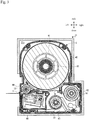
- Fig. 3 is a cross-sectional plan view taken at a middle position in the vertical direction of the tape cartridge C.
- the platen drive shaft 32, the reeling-side drive shaft 33, and the unreeling-side drive shaft 34 go through a bottom plate 21a of the cartridge attachment portion 21.
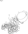
- a feeding power system 36 (see Fig. 4 ) for driving the platen drive shaft 32, the reeling-side drive shaft 33, and the unreeling-side drive shaft 34 for rotation is provided in a space under the bottom plate 21. A detailed explanation of the feeding power system 36 will be given later.
- a "ribbon feeding apparatus" is made up of the reeling-side drive shaft 33, the unreeling-side drive shaft 34, and the feeding power system 36.
- the print head 31 is a thermal print head in which plural heat generation elements (not illustrated) are arranged vertically in lines. Specifically, ink on an ink ribbon R is thermally transferred on a dot-by-dot basis onto a printing tape T by individually driving each of the heat generation elements provided in the print head 31 for generation of heat in a state in which the printing tape T and the ink ribbon R are nipped between the print head 31 and a platen roller 44 described later.
- the tape cartridge C includes: a tape reel 41, around which the printing tape T is wound in such a way that it can be unreeled, a ribbon unreeling core 42, around which the ink ribbon R is wound in such a way that it can be unreeled, a ribbon reeling core 43, onto which the ink ribbon R unreeled from the ribbon unreeling core 42 is reeled, a platen roller 44, which is opposite to the print head 31, and a cartridge case 45, in which they are housed.
- a head opening 46, into which the head cover 30 is to be inserted, is formed through the cartridge case 45.
- the head cover 30 When the tape cartridge C is attached into the cartridge attachment portion 21, the head cover 30 is inserted into the head opening 46, and the positioning protrusion 35 is inserted into the center hole of the tape reel 41.
- the center hole of the platen roller 44 is fitted onto the platen drive shaft 32, the center hole of the ribbon reeling core 43 is fitted onto the reeling-side drive shaft 33, and the center hole of the ribbon unreeling core 42 is fitted onto the unreeling-side drive shaft 34.
- the printing tape T is unreeled from the tape reel 41 into which the positioning protrusion 35 has been inserted.
- the printing tape T is fed to the tape ejection path 23 (tape feeding path).
- the ink ribbon R is unreeled from the ribbon unreeling core 42 having been fitted onto the unreeling-side drive shaft 34.
- the ink ribbon R goes around the surrounding walls of the head opening 46 to be reeled onto the ribbon reeling core 43 having been fitted onto the reeling-side drive shaft 33 (ribbon feeding path).
- the platen roller 44 While nipping the printing tape T and the ink ribbon R by working together with the print head 31, the platen roller 44 having been fitted onto the platen drive shaft 32 feeds the printing tape T in the forward direction and the reverse direction by being driven to rotate.
- the ribbon reeling core 43 having been fitted onto the reeling-side drive shaft 33 is driven to rotate in synchronization with forward feeding by the platen roller 44, thereby taking up the ink ribbon R.
- the ribbon unreeling core 42 having been fitted onto the unreeling-side drive shaft 34 is driven to rotate in synchronization with reverse feeding by the platen roller 44, thereby taking up (rewinding) the ink ribbon R.
- the printing tape T and the ink ribbon R are fed in the reverse direction to bring the leading end portion of the printing tape T back to the print position where printing is to be performed by the print head 31.
- print processing is performed onto the printing tape T by driving the print head 31 while feeding the printing tape T and the ink ribbon R in the forward direction.
- the printed part of the printing tape T is cut off by means of the tape cutter 24.
- the feeding power system 36 includes a drive motor 51, which is a power source that is able to rotate in the forward direction and the reverse direction, and a power transmission mechanism 52, which transmits the rotational power of the drive motor 51 to the platen drive shaft 32, the reeling-side drive shaft 33, and the unreeling-side drive shaft 34. That is, in the present embodiment, the drive motor 51 is used as a shared drive source for the platen drive shaft 32, the reeling-side drive shaft 33, and the unreeling-side drive shaft 34. The drive motor 51 is controlled for switching between forward rotation driving and reverse rotation driving by a control unit.
- the power transmission mechanism 52 includes a first clutch mechanism 61 (reeling-side clutch mechanism), into which motive power is inputted from the drive motor 51, an intermediate gear 62, which is in meshing engagement with a sun gear 72 of the first clutch mechanism 61, and a second clutch mechanism 63 (unreeling-side clutch mechanism), into which motive power is inputted from the intermediate gear 62.
- first clutch mechanism 61 coupling-side clutch mechanism
- intermediate gear 62 which is in meshing engagement with a sun gear 72 of the first clutch mechanism 61
- second clutch mechanism 63 unreeling-side clutch mechanism
- the power transmission mechanism 52 further includes a reeling-side gear train 64 (reeling-side power transmission mechanism), which transmits the inputted motive power to the reeling-side drive shaft 33, an unreeling-side gear train 65 (unreeling-side power transmission mechanism), which transmits the inputted motive power to the unreeling-side drive shaft 34, and a platen-side gear train 66, which transmits the inputted motive power to the platen drive shaft 32.
- the first clutch mechanism 61 establishes a connection between the drive motor 51 and the reeling-side gear train 64, and releases the connection.
- the second clutch mechanism 63 establishes a connection between the drive motor 51 and the unreeling-side gear train 65, and releases the connection.
- the platen-side gear train 66 is connected to a clutch input gear 81 of the second clutch mechanism 63 and is always connected to the drive motor 51.
- the first clutch mechanism 61 includes a clutch input gear 71, a sun gear 72 (reeling-side sun gear), a planet gear 73 (reeling-side planet gear), and a carrier 74 (clutch lever).
- the clutch input gear 71 is in meshing engagement with a gear 51a, which is formed on the drive shaft of the drive motor 51.
- the sun gear 72 is fixed coaxially with the clutch input gear 71 under the clutch input gear 71.
- the planet gear 73 is in meshing engagement with the sun gear 72.
- the carrier 74 supports the planet gear 73 rotatably.
- the carrier 74 is supported coaxially with the sun gear 72 in such a way as to be able to turn in an accompanying manner.
- the carrier 74 turns toward the right in Fig. 5 (accompanying turn). This turn brings the planet gear 73, which is supported by the carrier 74, out of meshing engagement with the reeling-side input gear 91, thereby disconnecting the drive motor 51 and the reeling-side gear train 64 from each other.
- the first clutch mechanism 61 establishes a connection between the drive motor 51 and the reeling-side gear train 64, and releases the connection, in accordance with the forward and reverse rotation of the drive motor 51.
- the sun gear 72 of the first clutch mechanism 61 is in meshing engagement with the intermediate gear 62, and the sun gear 72 is connected via the intermediate gear 62 to the second clutch mechanism 63. Therefore, irrespective of whether the drive motor 51 is driven to rotate in the forward direction or the reverse direction, the motive power of the drive motor 51 is inputted into the second clutch mechanism 63 via the intermediate gear 62 from the sun gear 72.
- the second clutch mechanism 63 includes a clutch input gear 81, a sun gear 82, a planet gear 83, and a carrier 84.
- the clutch input gear 81 is in meshing engagement with the intermediate gear 62.
- the sun gear 82 is fixed coaxially with the clutch input gear 81 under the clutch input gear 81.
- the planet gear 83 is in meshing engagement with the sun gear 82.
- the carrier 84 supports the planet gear 83 rotatably.
- the carrier 84 is supported coaxially with the sun gear 82 in such a way as to be able to turn in an accompanying manner.
- the sun gear 82 rotates in the reverse direction by being driven via the gears mentioned above due to this motor rotation. Because of the rotation of the sun gear 82 in the reverse direction, the carrier 84 turns upward in Fig. 5 (accompanying turn). This turn brings the planet gear 83, which is supported by the carrier 84, out of meshing engagement with the unreeling-side input gear 101, thereby disconnecting the drive motor 51 and the unreeling-side gear train 65 from each other. In this way, the second clutch mechanism 63 establishes a connection between the drive motor 51 and the unreeling-side gear train 65, and releases the connection, in accordance with the forward and reverse rotation of the drive motor 51.
- the reeling-side gear train 64 includes a reeling-side input gear 91, a reeling-side first intermediate gear 92, a reeling-side second intermediate gear 93, a reeling-side third intermediate gear 94, a reeling-side fourth intermediate gear 95, a reeling-side fifth intermediate gear 96, a reeling-side sixth intermediate gear 97, and a reeling-side output gear 98.
- the reeling-side input gear 91 is configured to be in meshing engagement with the planet gear 73 of the first clutch mechanism 61.
- the reeling-side first intermediate gear 92 is fixed coaxially with the reeling-side input gear 91 under the reeling-side input gear 91.
- the reeling-side second intermediate gear 93 is in meshing engagement with the reeling-side first intermediate gear 92.
- the reeling-side third intermediate gear 94 is in meshing engagement with the reeling-side second intermediate gear 93.
- the reeling-side fourth intermediate gear 95 is fixed coaxially with the reeling-side third intermediate gear 94 over the reeling-side third intermediate gear 94.
- the reeling-side fifth intermediate gear 96 is in meshing engagement with the reeling-side fourth intermediate gear 95.
- the reeling-side sixth intermediate gear 97 is fixed coaxially with the reeling-side fifth intermediate gear 96 under the reeling-side fifth intermediate gear 96.
- the reeling-side output gear 98 is in meshing engagement with the reeling-side sixth intermediate gear 97, and supports the reeling-side drive shaft 33.
- the reeling-side second intermediate gear 93 is provided coaxially with the clutch input gear 81 and the sun gear 82 of the second clutch mechanism 63 directly under the clutch input gear 81.
- the reeling-side second intermediate gear 93 is configured to be able to rotate independently of the clutch input gear 81 and the sun gear 82 of the second clutch mechanism 63.
- a tension spring (torsion-spring-type torque limiter) (not illustrated) is mounted between the reeling-side drive shaft 33 and the reeling-side output gear 98.
- the reeling-side drive shaft 33 is rotationally urged in the taking-up direction by the tension spring. This urging applies a predetermined tension to the ink ribbon R.
- the unreeling-side gear train 65 includes an unreeling-side input gear 101, an unreeling-side intermediate gear 102, and an unreeling-side output gear 103.
- the unreeling-side input gear 101 is configured to be in meshing engagement with the planet gear 83 of the second clutch mechanism 63.
- the unreeling-side intermediate gear 102 is fixed coaxially with the unreeling-side input gear 101 under the unreeling-side input gear 101.
- the unreeling-side output gear 103 is in meshing engagement with the unreeling-side intermediate gear 102, and supports the unreeling-side drive shaft 34.
- a tension spring 104 (torsion-spring-type torque limiter) is mounted between the unreeling-side drive shaft 34 and the unreeling-side output gear 103.
- the unreeling-side drive shaft 34 is rotationally urged in the taking-up direction by the tension spring. This urging applies a predetermined tension to the ink ribbon R.
- the platen-side gear train 66 includes a platen-side input gear 111, a platen-side first intermediate gear 112, a platen-side second intermediate gear 113, a platen-side third intermediate gear 114, and a platen-side output gear 115.
- the platen-side input gear 111 is in meshing engagement with the clutch input gear 81 of the second clutch mechanism 63.
- the platen-side first intermediate gear 112 is fixed coaxially with the platen-side input gear 111 over the platen-side input gear 111.
- the platen-side second intermediate gear 113 is in meshing engagement with the platen-side first intermediate gear 112.
- the platen-side third intermediate gear 114 is fixed coaxially with the platen-side second intermediate gear 113 over the platen-side second intermediate gear 113.
- the platen-side output gear 115 is in meshing engagement with the platen-side third intermediate gear 114, and supports the platen drive shaft 32. Because of the structure described above, motive power inputted into the platen-side input gear 111 from the clutch input gear 81 of the second clutch mechanism 63 is transmitted to the platen drive shaft 32.
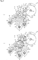
- the reverse feeding drive operation is the operation of switching the connection to the drive motor 51 from the side of the reeling-side drive shaft 33 to the side of the unreeling-side drive shaft 34 by causing the drive motor 51 to rotate in the reverse direction and of causing the platen drive shaft 32 and the unreeling-side drive shaft 34 to rotate.
- the motive power produced by the reverse rotation of the drive motor 51 is inputted into the clutch input gear 81 of the second clutch mechanism 63 via the intermediate gear 62 from the sun gear 72 of the first clutch mechanism 61.
- the clutch input gear 81 rotates by receiving the inputted power, and the sun gear 82 fixed thereto rotates in the forward direction.
- the rotation of the sun gear 82 in the forward direction causes the carrier 84 to turn in an accompanying manner downward in the drawing, thereby bringing the planet gear 83 into meshing engagement with the unreeling-side input gear 101 of the unreeling-side gear train 65.
- a connection between the drive motor 51 and the unreeling-side gear train 65 is established. Because of this connection, the power of the drive motor 51 is transmitted to the unreeling-side gear train 65, and then to the unreeling-side drive shaft 34.
- the unreeling-side drive shaft 34 rotates due to the reverse rotation of the drive motor 51. Accordingly, the ribbon unreeling core 42, which is in engagement with the unreeling-side drive shaft 34, is driven to rotate in the taking-up direction.
- the motive power produced by the reverse rotation of the drive motor 51 is inputted into the platen-side gear train 66 from the clutch input gear 81 of the second clutch mechanism 63.
- the motive power is transmitted via the platen-side gear train 66 to the platen drive shaft 32, and the platen drive shaft 32 rotates in the reverse direction.
- the platen roller 44 which is in engagement with the platen drive shaft 32, is driven to rotate in the reverse direction.
- the driving of the platen roller 44 for rotation in the reverse direction and the driving of the ribbon unreeling core 42 in the taking-up direction are performed at the same time in synchronization with each other. As a result of this operation, the printing tape T and the ink ribbon R are fed in the reverse direction.
- the forward feeding drive operation is the operation of switching the connection to the drive motor 51 from the side of the unreeling-side drive shaft 34 to the side of the reeling-side drive shaft 33 by causing the drive motor 51 to rotate in the forward direction and of causing the platen drive shaft 32 and the reeling-side drive shaft 33 to rotate.
- the power of the drive motor 51 is transmitted to the reeling-side gear train 64, and then to the reeling-side drive shaft 33. Therefore, the reeling-side drive shaft 33 rotates due to the forward rotation of the drive motor 51. Accordingly, the ribbon reeling core 43, which is in engagement with the reeling-side drive shaft 33, is driven to rotate in the taking-up direction.
- the motive power produced by the forward rotation of the drive motor 51 is inputted into the clutch input gear 81 of the second clutch mechanism 63 via the intermediate gear 62 from the sun gear 72 of the first clutch mechanism 61.
- the clutch input gear 81 rotates by receiving the inputted power, and the sun gear 82 fixed thereto rotates in the reverse direction.
- the rotation of the sun gear 82 in the reverse direction causes the carrier 84 to turn in an accompanying manner upward in the drawing, thereby bringing the planet gear 83 out of meshing engagement with the unreeling-side input gear 101 of the unreeling-side gear train 65.
- the connection between the drive motor 51 and the unreeling-side gear train 65 is released.
- the motive power produced by the forward rotation of the drive motor 51 is inputted into the platen-side gear train 66 from the clutch input gear 81 of the second clutch mechanism 63.
- the motive power is transmitted via the platen-side gear train 66 to the platen drive shaft 32, and the platen drive shaft 32 rotates in the forward direction.
- the platen roller 44 which is in engagement with the platen drive shaft 32, is driven to rotate in the forward direction.
- the driving of the platen roller 44 for rotation in the forward direction and the driving of the ribbon reeling core 43 in the taking-up direction are performed at the same time in synchronization with each other. As a result of this operation, the printing tape T and the ink ribbon R are fed in the forward direction.
- print processing is performed by feeding the printing tape T in the forward direction after bringing the leading end portion of the printing tape T back to the print position where printing is to be performed by the print head 31 by feeding the printing tape T in the reverse direction, it is possible to proceed into the print processing immediately after the pulling of the leading end portion of the printing tape T back.
- the reeling-side first clutch mechanism,61 is provided upstream of the sun gear 82 of the unreeling-side second clutch mechanism 63.
- the unreeling-side second clutch mechanism 63 may be provided upstream of the sun gear 72 of the reeling-side first clutch mechanism 61. That is, although a priority is given to the solution of problems (e.g., delay in switchover) arising when the connection to the drive motor 51 is switched from the unreeling side to the reeling side in the embodiment described above, similar problems could arise in switchover from the reeling side to the unreeling side because a tension spring is mounted on the reeling-side drive shaft 33, too.
- problems e.g., delay in switchover
- a conceivable structure for addressing this issue is to give a priority to the solution of problems arising in switchover from the reeling side to the unreeling side and to provide the unreeling-side second clutch mechanism 63 upstream of the sun gear 72 of the reeling-side first clutch mechanism 61.
- a second gear train branching off from the gear train leading to the unreeling-side second clutch mechanism 63 may be provided, and the reeling-side first clutch mechanism 61 may be provided on the second gear train. That is, the gear train may bifurcate upstream of each of the clutch mechanisms 61 and 63, and each of the clutch mechanisms 61 and 63 may be provided on the corresponding one of the two branch gear trains.
Landscapes
- Impression-Transfer Materials And Handling Thereof (AREA)
- Printers Characterized By Their Purpose (AREA)
Abstract
Description
- The present invention relates to a ribbon feeding apparatus that feeds an ink ribbon in a forward direction and a reverse direction, and a tape printing apparatus equipped with the same.
- In prior art, as a tape printing apparatus (printer) of this kind, a known apparatus includes a two-way drive mechanism that feeds an ink ribbon in a feed direction and a reverse feed direction by driving, for rotation, a ribbon unreeling core (ink ribbon supply spool) around which the ink ribbon is wound in such a way that it can be unreeled, and a ribbon reeling core (ink ribbon taking-up spool) onto which the ink ribbon unreeled from the ribbon unreeling core is reeled (see Patent Literature 1). The two-way drive mechanism includes: a drive motor, an ink ribbon supply gear that supports a ribbon supply shaft that is in engagement with the ribbon unreeling core, an ink ribbon taking-up gear that supports a ribbon taking-up shaft that is in engagement with the ribbon reeling core, and a pivotal drive gear assembly.
- The pivotal drive gear assembly includes: a pivotal gear that is connected via a gear train to the drive motor, a gear plate that turns in an accompanying manner as the pivotal gear rotates, and a first moving gear and a second moving gear that are mounted rotatably on the gear plate. The first moving gear is in meshing engagement with the pivotal gear and is brought into and out of meshing engagement with the ink ribbon taking-up gear as the gear plate turns. The second moving gear is in meshing engagement with the first moving gear and is brought into and out of meshing engagement with the ink ribbon supply gear as the gear plate turns. In the two-way drive mechanism described above, when the drive motor is driven to rotate in the forward direction, the gear plate turns toward the ink ribbon taking-up gear to bring the first moving gear into meshing engagement with the ink ribbon taking-up gear. As a result of this operation, the drive motor and the ink ribbon taking-up gear get connected to each other via the gear train, and, in this state, the ribbon reeling core is able to be driven to rotate by the drive motor. When the drive motor is driven to rotate in the reverse direction, the gear plate turns toward the ink ribbon supply gear to bring the second moving gear into meshing engagement with the ink ribbon supply gear. As a result of this operation, the drive motor and the ink ribbon supply gear get connected to each other via the gear train, and, in this state, the ribbon unreeling core is able to be driven to rotate by the drive motor. In this way, it is possible to switch the connection to the drive motor between the ink ribbon taking-up gear and the ink ribbon supply gear in accordance with the forward and reverse rotation of the drive motor.
- Patent Literature 1: Japanese Unexamined Patent Application Publication (Translation of PCT Application) No.
2007-502221 - However, in the above tape printing apparatus according to prior art, the following problems arise when the connection to the drive motor is switched from the ink ribbon supply gear to the ink ribbon taking-up gear.
- In a tape printing apparatus of this kind, it is common that a tension spring (torque limiter) for applying a predetermined tension to an ink ribbon is mounted between an ink ribbon supply gear and an ink ribbon taking-up gear. Therefore, in the above tape printing apparatus according to prior art, when the connection to the drive motor is switched from the ink ribbon supply gear to the ink ribbon taking-up gear, a force accumulated in the tension spring (slip torque) interferes with the pivotal gear via the ink ribbon supply gear, the second moving gear, and the first moving gear, thereby obstructing the rotation of the pivotal gear. Since this interference causes a time lag in the rotation of the pivotal gear and a time lag in the turning of the gear plate, it is impossible to perform the connection switchover speedily.
- Moreover, in the above tape printing apparatus according to prior art, the tension applied to the ink ribbon is released suddenly at the timing when the second moving gear is brought out of meshing engagement with the ink ribbon supply gear. Therefore, loosening in the ink ribbon wound occurs.
- An object of the present invention is to provide a ribbon feeding apparatus that makes it possible to, with a simple structure, solve problems arising when a connection to a drive motor is switched from an unreeling side to a reeling side, and provide a tape printing apparatus equipped with the same.
- A ribbon feeding apparatus according to the present invention is an apparatus that feeds an ink ribbon in a forward direction and a reverse direction by driving a ribbon unreeling core and a ribbon reeling core for rotation, the ink ribbon being unreeled from the ribbon unreeling core, the ink ribbon unreeled from the ribbon unreeling core being reeled onto the ribbon reeling core, the apparatus comprising: a drive motor; an unreeling-side drive shaft that is in engagement with the ribbon unreeling core; an unreeling-side power transmission mechanism that transmits inputted motive power to the unreeling-side drive shaft; a reeling-side drive shaft that is in engagement with the ribbon reeling core; a reeling-side power transmission mechanism that transmits inputted motive power to the reeling-side drive shaft; an unreeling-side clutch mechanism that includes a sun gear and a planet gear, connects the drive motor and the unreeling-side power transmission mechanism to each other in accordance with reverse rotation of the drive motor, and disconnects the drive motor and the unreeling-side power transmission mechanism from each other in accordance with forward rotation of the drive motor, the planet gear being in meshing engagement with the sun gear and being brought into and out of meshing engagement with the reeling-side power transmission mechanism; and a reeling-side clutch mechanism that is provided upstream of the sun gear, connects the drive motor and the reeling-side power transmission mechanism to each other in accordance with the forward rotation of the drive motor, and disconnects the drive motor and the reeling-side power transmission mechanism from each other in accordance with the reverse rotation of the drive motor.
- In this case, preferably, the reeling-side clutch mechanism should include a reeling-side sun gear that is provided upstream of the sun gear, and a reeling-side planet gear that is in meshing engagement with the sun gear and is brought into and out of meshing engagement with the unreeling-side power transmission mechanism.
- A tape printing apparatus according to the present invention comprises the above ribbon feeding apparatus.
- With the structure of these apparatuses, because of the separation of a clutch mechanism into the clutch mechanism at the unreeling side (unreeling-side clutch mechanism) and the clutch mechanism at the reeling side (reeling-side clutch mechanism), it is possible to establish a connection to the drive motor and release the connection at the reeling-side clutch mechanism almost without any interference from the tension spring. Therefore, when the connection to the drive motor is switched from the unreeling-side power transmission mechanism to the reeling-side power transmission mechanism, it is possible to establish a speedy connection between the drive motor and the reeling-side power transmission mechanism, thereby realizing speedy switchover from the unreeling-side power transmission mechanism to the reeling-side power transmission mechanism. Moreover, since the timing of activation of the reeling-side clutch mechanism is slightly earlier than the timing of activation of the unreeling-side clutch mechanism, the drive motor and the reeling-side power transmission mechanism get connected to each other before the disconnection of the drive motor and the unreeling-side power transmission mechanism from each other. That is, there exists a state of temporary connection to both of the power transmission mechanisms in the process of switchover. For this reason, the tension applied to the ink ribbon is released gradually, without a sudden release; therefore, it is possible to prevent the occurrence of loosening in the ink ribbon wound. As described herein, with a simple structure, it is possible to solve problems arising when the connection to the drive motor is switched from the unreeling side to the reeling side.
-
- [
Fig. 1 ] An external perspective view of a tape printing apparatus according to an exemplary embodiment that is in a cover-closed state; - [
Fig. 2 ] An external perspective view of the tape printing apparatus that is in a cover-opened state; - [
Fig. 3 ] A cross-sectional plan view of a cartridge attachment portion, and a tape cartridge attached to the cartridge attachment portion; - [
Fig. 4 ] A perspective view of a feeding power system; - [
Fig. 5 ] A plan view of the feeding power system; - [
Fig. 6 ] (a) A diagram for explaining reverse feeding drive operation performed by the feeding power system; (b) A diagram for explaining forward feeding drive operation performed by the feeding power system; - With reference to the accompanying drawings, a ribbon feeding apparatus according to an embodiment of the present invention, and a tape printing apparatus equipped with the same, will now be explained. The tape printing apparatus performs printing while unreeling a printing tape and an ink ribbon from an attached tape cartridge, and cuts a printed part of the printing tape off to create a label (tape strip).
- As illustrated in
Figs. 1 and2 , the exterior of a tape printing apparatus 1 is made of anapparatus case 11, and akeyboard 12 including various keys is provided on the top of the front portion of theapparatus case 11. A wide open/close cover 13 is provided on the top, at the left-hand side, of the rear portion of theapparatus case 11, and a coveropen button 14, which is for opening the open/close cover 13, is provided in front of the open/close cover 13. Arectangular display 15 for displaying the result of an input via thekeyboard 12, etc. is provided on the top, at the right-hand side, of the rear portion of theapparatus case 11. - A
cartridge attachment portion 21, into which a tape cartridge C is to be detachably attached, is formed as a cavity appearing inside when the coveropen button 14 is pressed to open the open/close cover 13. The tape cartridge C is attached into thecartridge attachment portion 21 in a state in which the open/close cover 13 is open. - A
tape exit 22, which is in communication with thecartridge attachment portion 21, is formed in the left side of theapparatus case 11, and atape ejection path 23 is formed between thecartridge attachment portion 21 and thetape exit 22. Atape cutter 24 is built across thetape ejection path 23 inside theapparatus case 11. - As illustrated in
Figs. 2 and3 , a thermal-type print head 31, which is housed in ahead cover 30, aplaten drive shaft 32, which is opposite to theprint head 31, a reeling-side drive shaft 33, which is in engagement with aribbon reeling core 43 described later, an unreeling-side drive shaft 34, which is in engagement with a ribbonunreeling core 42 described later, and aprotrusion 35, which is for positioning atape reel 41 described later, are provided in thecartridge attachment portion 21.Fig. 3 is a cross-sectional plan view taken at a middle position in the vertical direction of the tape cartridge C. Theplaten drive shaft 32, the reeling-side drive shaft 33, and the unreeling-side drive shaft 34 go through abottom plate 21a of thecartridge attachment portion 21. A feeding power system 36 (seeFig. 4 ) for driving theplaten drive shaft 32, the reeling-side drive shaft 33, and the unreeling-side drive shaft 34 for rotation is provided in a space under thebottom plate 21. A detailed explanation of thefeeding power system 36 will be given later. A "ribbon feeding apparatus" is made up of the reeling-side drive shaft 33, the unreeling-side drive shaft 34, and thefeeding power system 36. - The
print head 31 is a thermal print head in which plural heat generation elements (not illustrated) are arranged vertically in lines. Specifically, ink on an ink ribbon R is thermally transferred on a dot-by-dot basis onto a printing tape T by individually driving each of the heat generation elements provided in theprint head 31 for generation of heat in a state in which the printing tape T and the ink ribbon R are nipped between theprint head 31 and aplaten roller 44 described later. - On the other hand, the tape cartridge C includes: a
tape reel 41, around which the printing tape T is wound in such a way that it can be unreeled, a ribbonunreeling core 42, around which the ink ribbon R is wound in such a way that it can be unreeled, aribbon reeling core 43, onto which the ink ribbon R unreeled from the ribbonunreeling core 42 is reeled, aplaten roller 44, which is opposite to theprint head 31, and acartridge case 45, in which they are housed. A head opening 46, into which thehead cover 30 is to be inserted, is formed through thecartridge case 45. - When the tape cartridge C is attached into the
cartridge attachment portion 21, thehead cover 30 is inserted into the head opening 46, and thepositioning protrusion 35 is inserted into the center hole of thetape reel 41. In addition, at the same time, the center hole of theplaten roller 44 is fitted onto theplaten drive shaft 32, the center hole of theribbon reeling core 43 is fitted onto the reeling-side drive shaft 33, and the center hole of the ribbonunreeling core 42 is fitted onto the unreeling-side drive shaft 34. - As illustrated in
Fig. 3 , the printing tape T is unreeled from thetape reel 41 into which thepositioning protrusion 35 has been inserted. After passing through the position where theprint head 31 and theplaten roller 44 face each other, the printing tape T is fed to the tape ejection path 23 (tape feeding path). On the other hand, the ink ribbon R is unreeled from the ribbonunreeling core 42 having been fitted onto the unreeling-side drive shaft 34. After passing through the position where theprint head 31 and theplaten roller 44 face each other, the ink ribbon R goes around the surrounding walls of the head opening 46 to be reeled onto theribbon reeling core 43 having been fitted onto the reeling-side drive shaft 33 (ribbon feeding path). - While nipping the printing tape T and the ink ribbon R by working together with the
print head 31, theplaten roller 44 having been fitted onto theplaten drive shaft 32 feeds the printing tape T in the forward direction and the reverse direction by being driven to rotate. Theribbon reeling core 43 having been fitted onto the reeling-side drive shaft 33 is driven to rotate in synchronization with forward feeding by theplaten roller 44, thereby taking up the ink ribbon R. Theribbon unreeling core 42 having been fitted onto the unreeling-side drive shaft 34 is driven to rotate in synchronization with reverse feeding by theplaten roller 44, thereby taking up (rewinding) the ink ribbon R. By these drive rotations, the printing tape T and the ink ribbon R are fed in the forward direction and the reverse direction. - In label creation operation according to the present embodiment, first, the printing tape T and the ink ribbon R are fed in the reverse direction to bring the leading end portion of the printing tape T back to the print position where printing is to be performed by the
print head 31. After that, print processing is performed onto the printing tape T by driving theprint head 31 while feeding the printing tape T and the ink ribbon R in the forward direction. After completion of the print processing, the printed part of the printing tape T is cut off by means of thetape cutter 24. By this means, it is possible to create a label that has no white space arising from the distance between the head and the cutter. - With reference to
Figs. 4 and5 , the feedingpower system 36 will now be explained in detail. As illustrated inFigs. 4 and5 , the feedingpower system 36 includes adrive motor 51, which is a power source that is able to rotate in the forward direction and the reverse direction, and apower transmission mechanism 52, which transmits the rotational power of thedrive motor 51 to theplaten drive shaft 32, the reeling-side drive shaft 33, and the unreeling-side drive shaft 34. That is, in the present embodiment, thedrive motor 51 is used as a shared drive source for theplaten drive shaft 32, the reeling-side drive shaft 33, and the unreeling-side drive shaft 34. Thedrive motor 51 is controlled for switching between forward rotation driving and reverse rotation driving by a control unit. - The
power transmission mechanism 52 includes a first clutch mechanism 61 (reeling-side clutch mechanism), into which motive power is inputted from thedrive motor 51, anintermediate gear 62, which is in meshing engagement with asun gear 72 of the firstclutch mechanism 61, and a second clutch mechanism 63 (unreeling-side clutch mechanism), into which motive power is inputted from theintermediate gear 62. Thepower transmission mechanism 52 further includes a reeling-side gear train 64 (reeling-side power transmission mechanism), which transmits the inputted motive power to the reeling-side drive shaft 33, an unreeling-side gear train 65 (unreeling-side power transmission mechanism), which transmits the inputted motive power to the unreeling-side drive shaft 34, and a platen-side gear train 66, which transmits the inputted motive power to theplaten drive shaft 32. The firstclutch mechanism 61 establishes a connection between thedrive motor 51 and the reeling-side gear train 64, and releases the connection. The secondclutch mechanism 63 establishes a connection between thedrive motor 51 and the unreeling-side gear train 65, and releases the connection. On the other hand, the platen-side gear train 66 is connected to aclutch input gear 81 of the secondclutch mechanism 63 and is always connected to thedrive motor 51. - The first
clutch mechanism 61 includes aclutch input gear 71, a sun gear 72 (reeling-side sun gear), a planet gear 73 (reeling-side planet gear), and a carrier 74 (clutch lever). Theclutch input gear 71 is in meshing engagement with agear 51a, which is formed on the drive shaft of thedrive motor 51. Thesun gear 72 is fixed coaxially with theclutch input gear 71 under theclutch input gear 71. Theplanet gear 73 is in meshing engagement with thesun gear 72. Thecarrier 74 supports theplanet gear 73 rotatably. In addition, thecarrier 74 is supported coaxially with thesun gear 72 in such a way as to be able to turn in an accompanying manner. When thedrive motor 51 is driven to rotate in the forward direction, thesun gear 72 rotates in the forward direction by being driven via theclutch input gear 71 due to this motor rotation. Because of this gear rotation in the forward direction, thecarrier 74 turns toward the left inFig. 5 (accompanying turn). This turn brings theplanet gear 73, which is supported by thecarrier 74, into meshing engagement with an input gear (reeling-side input gear 91) of the reeling-side gear train 64, thereby connecting thedrive motor 51 and the reeling-side gear train 64 to each other. On the other hand, when thedrive motor 51 is driven to rotate in the reverse direction, thesun gear 72 rotates in the reverse direction by being driven via theclutch input gear 71 due to this motor rotation. Because of the rotation of thesun gear 72 in the reverse direction, thecarrier 74 turns toward the right inFig. 5 (accompanying turn). This turn brings theplanet gear 73, which is supported by thecarrier 74, out of meshing engagement with the reeling-side input gear 91, thereby disconnecting thedrive motor 51 and the reeling-side gear train 64 from each other. In this way, the firstclutch mechanism 61 establishes a connection between thedrive motor 51 and the reeling-side gear train 64, and releases the connection, in accordance with the forward and reverse rotation of thedrive motor 51. - As mentioned above, the
sun gear 72 of the firstclutch mechanism 61 is in meshing engagement with theintermediate gear 62, and thesun gear 72 is connected via theintermediate gear 62 to the secondclutch mechanism 63. Therefore, irrespective of whether thedrive motor 51 is driven to rotate in the forward direction or the reverse direction, the motive power of thedrive motor 51 is inputted into the secondclutch mechanism 63 via theintermediate gear 62 from thesun gear 72. - The second
clutch mechanism 63 includes aclutch input gear 81, asun gear 82, aplanet gear 83, and acarrier 84. Theclutch input gear 81 is in meshing engagement with theintermediate gear 62. Thesun gear 82 is fixed coaxially with theclutch input gear 81 under theclutch input gear 81. Theplanet gear 83 is in meshing engagement with thesun gear 82. Thecarrier 84 supports theplanet gear 83 rotatably. In addition, thecarrier 84 is supported coaxially with thesun gear 82 in such a way as to be able to turn in an accompanying manner. When thedrive motor 51 is driven to rotate in the reverse direction, thesun gear 82 rotates in the forward direction by being driven via theclutch input gear 71, thesun gear 72, theintermediate gear 62, and theclutch input gear 81 due to this motor rotation. Because of this gear rotation in the forward direction, thecarrier 84 turns downward inFig. 5 (accompanying turn). This turn brings theplanet gear 83, which is supported by thecarrier 84, into meshing engagement with an input gear (unreeling-side input gear 101) of the unreeling-side gear train 65, thereby connecting thedrive motor 51 and the unreeling-side gear train 65 to each other. On the other hand, when thedrive motor 51 is driven to rotate in the forward direction, thesun gear 82 rotates in the reverse direction by being driven via the gears mentioned above due to this motor rotation. Because of the rotation of thesun gear 82 in the reverse direction, thecarrier 84 turns upward inFig. 5 (accompanying turn). This turn brings theplanet gear 83, which is supported by thecarrier 84, out of meshing engagement with the unreeling-side input gear 101, thereby disconnecting thedrive motor 51 and the unreeling-side gear train 65 from each other. In this way, the secondclutch mechanism 63 establishes a connection between thedrive motor 51 and the unreeling-side gear train 65, and releases the connection, in accordance with the forward and reverse rotation of thedrive motor 51. - The reeling-
side gear train 64 includes a reeling-side input gear 91, a reeling-side firstintermediate gear 92, a reeling-side secondintermediate gear 93, a reeling-side thirdintermediate gear 94, a reeling-side fourthintermediate gear 95, a reeling-side fifthintermediate gear 96, a reeling-side sixthintermediate gear 97, and a reeling-side output gear 98. The reeling-side input gear 91 is configured to be in meshing engagement with theplanet gear 73 of the firstclutch mechanism 61. The reeling-side firstintermediate gear 92 is fixed coaxially with the reeling-side input gear 91 under the reeling-side input gear 91. The reeling-side secondintermediate gear 93 is in meshing engagement with the reeling-side firstintermediate gear 92. The reeling-side thirdintermediate gear 94 is in meshing engagement with the reeling-side secondintermediate gear 93. The reeling-side fourthintermediate gear 95 is fixed coaxially with the reeling-side thirdintermediate gear 94 over the reeling-side thirdintermediate gear 94. The reeling-side fifthintermediate gear 96 is in meshing engagement with the reeling-side fourthintermediate gear 95. The reeling-side sixthintermediate gear 97 is fixed coaxially with the reeling-side fifthintermediate gear 96 under the reeling-side fifthintermediate gear 96. The reeling-side output gear 98 is in meshing engagement with the reeling-side sixthintermediate gear 97, and supports the reeling-side drive shaft 33. Because of the structure described above, motive power inputted into the reeling-side input gear 91 from theplanet gear 73 of the firstclutch mechanism 61 is transmitted to the reeling-side drive shaft 33. The reeling-side secondintermediate gear 93 is provided coaxially with theclutch input gear 81 and thesun gear 82 of the secondclutch mechanism 63 directly under theclutch input gear 81. In addition, the reeling-side secondintermediate gear 93 is configured to be able to rotate independently of theclutch input gear 81 and thesun gear 82 of the secondclutch mechanism 63. - A tension spring (torsion-spring-type torque limiter) (not illustrated) is mounted between the reeling-
side drive shaft 33 and the reeling-side output gear 98. The reeling-side drive shaft 33 is rotationally urged in the taking-up direction by the tension spring. This urging applies a predetermined tension to the ink ribbon R. - The unreeling-
side gear train 65 includes an unreeling-side input gear 101, an unreeling-sideintermediate gear 102, and an unreeling-side output gear 103. The unreeling-side input gear 101 is configured to be in meshing engagement with theplanet gear 83 of the secondclutch mechanism 63. The unreeling-sideintermediate gear 102 is fixed coaxially with the unreeling-side input gear 101 under the unreeling-side input gear 101. The unreeling-side output gear 103 is in meshing engagement with the unreeling-sideintermediate gear 102, and supports the unreeling-side drive shaft 34. Because of the structure described above, motive power inputted into the reeling-side input gear 91 from theplanet gear 83 of the secondclutch mechanism 63 is transmitted to the unreeling-side drive shaft 34. A tension spring 104 (torsion-spring-type torque limiter) is mounted between the unreeling-side drive shaft 34 and the unreeling-side output gear 103. The unreeling-side drive shaft 34 is rotationally urged in the taking-up direction by the tension spring. This urging applies a predetermined tension to the ink ribbon R. - The platen-
side gear train 66 includes a platen-side input gear 111, a platen-side firstintermediate gear 112, a platen-side secondintermediate gear 113, a platen-side thirdintermediate gear 114, and a platen-side output gear 115. The platen-side input gear 111 is in meshing engagement with theclutch input gear 81 of the secondclutch mechanism 63. The platen-side firstintermediate gear 112 is fixed coaxially with the platen-side input gear 111 over the platen-side input gear 111. The platen-side secondintermediate gear 113 is in meshing engagement with the platen-side firstintermediate gear 112. The platen-side thirdintermediate gear 114 is fixed coaxially with the platen-side secondintermediate gear 113 over the platen-side secondintermediate gear 113. The platen-side output gear 115 is in meshing engagement with the platen-side thirdintermediate gear 114, and supports theplaten drive shaft 32. Because of the structure described above, motive power inputted into the platen-side input gear 111 from theclutch input gear 81 of the secondclutch mechanism 63 is transmitted to theplaten drive shaft 32. - Next, with reference to
Fig. 6 , forward feeding drive operation and reverse feeding drive operation performed by the feedingpower system 36 will now be explained. First, with reference toFig. 6(a) , reverse feeding drive operation will now be explained. The reverse feeding drive operation is the operation of switching the connection to thedrive motor 51 from the side of the reeling-side drive shaft 33 to the side of the unreeling-side drive shaft 34 by causing thedrive motor 51 to rotate in the reverse direction and of causing theplaten drive shaft 32 and the unreeling-side drive shaft 34 to rotate. It is assumed herein that this operation is performed from a state in which theplanet gear 73 has been brought into meshing engagement with the reeling-side gear train 64 due to the turning of thecarrier 74 of the firstclutch mechanism 61 leftward in the drawing and in which theplanet gear 83 has been brought out of meshing engagement with the unreeling-side gear train 65 due to the turning of thecarrier 84 of the secondclutch mechanism 63 upward in the drawing. - As illustrated in
Fig. 6(a) , when thedrive motor 51 is driven to rotate in the reverse direction, its power is inputted into theclutch input gear 71 of the firstclutch mechanism 61. In the firstclutch mechanism 61, theclutch input gear 71 rotates by receiving the inputted power, and thesun gear 72 fixed thereto rotates in the reverse direction. The rotation of thesun gear 72 in the reverse direction causes thecarrier 74 to turn in an accompanying manner toward the right in the drawing, thereby bringing theplanet gear 73 out of meshing engagement with the reeling-side input gear 91 of the reeling-side gear train 64. As a result of this operation, the connection between thedrive motor 51 and the reeling-side gear train 64 is released. - On the other hand, the motive power produced by the reverse rotation of the
drive motor 51 is inputted into theclutch input gear 81 of the secondclutch mechanism 63 via theintermediate gear 62 from thesun gear 72 of the firstclutch mechanism 61. - In the second
clutch mechanism 63, theclutch input gear 81 rotates by receiving the inputted power, and thesun gear 82 fixed thereto rotates in the forward direction. The rotation of thesun gear 82 in the forward direction causes thecarrier 84 to turn in an accompanying manner downward in the drawing, thereby bringing theplanet gear 83 into meshing engagement with the unreeling-side input gear 101 of the unreeling-side gear train 65. As a result of this operation, a connection between thedrive motor 51 and the unreeling-side gear train 65 is established. Because of this connection, the power of thedrive motor 51 is transmitted to the unreeling-side gear train 65, and then to the unreeling-side drive shaft 34. Therefore, the unreeling-side drive shaft 34 rotates due to the reverse rotation of thedrive motor 51. Accordingly, theribbon unreeling core 42, which is in engagement with the unreeling-side drive shaft 34, is driven to rotate in the taking-up direction. - In addition, the motive power produced by the reverse rotation of the
drive motor 51 is inputted into the platen-side gear train 66 from theclutch input gear 81 of the secondclutch mechanism 63. The motive power is transmitted via the platen-side gear train 66 to theplaten drive shaft 32, and theplaten drive shaft 32 rotates in the reverse direction. Because of this operation, theplaten roller 44, which is in engagement with theplaten drive shaft 32, is driven to rotate in the reverse direction. As described above, the driving of theplaten roller 44 for rotation in the reverse direction and the driving of theribbon unreeling core 42 in the taking-up direction are performed at the same time in synchronization with each other. As a result of this operation, the printing tape T and the ink ribbon R are fed in the reverse direction. - Next, with reference to Fig. 6(f), forward feeding drive operation will now be explained. The forward feeding drive operation is the operation of switching the connection to the
drive motor 51 from the side of the unreeling-side drive shaft 34 to the side of the reeling-side drive shaft 33 by causing thedrive motor 51 to rotate in the forward direction and of causing theplaten drive shaft 32 and the reeling-side drive shaft 33 to rotate. It is assumed herein that this operation is performed from a state in which theplanet gear 73 has been brought out of meshing engagement with the reeling-side gear train 64 due to the turning of thecarrier 74 of the firstclutch mechanism 61 rightward in the drawing and in which theplanet gear 83 has been brought into meshing engagement with the unreeling-side gear train 65 due to the turning of thecarrier 84 of the secondclutch mechanism 63 downward in the drawing. - As illustrated in
Fig. 6(b) , when thedrive motor 51 is driven to rotate in the forward direction, its power is inputted into theclutch input gear 71 of the firstclutch mechanism 61. In the firstclutch mechanism 61, theclutch input gear 71 rotates by receiving the inputted power, and thesun gear 72 fixed thereto rotates in the forward direction. The rotation of thesun gear 72 in the forward direction causes thecarrier 74 to turn in an accompanying manner toward the left in the drawing, thereby bringing theplanet gear 73 into meshing engagement with the reeling-side input gear 91 of the reeling-side gear train 64. As a result of this operation, a connection between thedrive motor 51 and the reeling-side gear train 64 is established. Because of this connection, the power of thedrive motor 51 is transmitted to the reeling-side gear train 64, and then to the reeling-side drive shaft 33. Therefore, the reeling-side drive shaft 33 rotates due to the forward rotation of thedrive motor 51. Accordingly, theribbon reeling core 43, which is in engagement with the reeling-side drive shaft 33, is driven to rotate in the taking-up direction. - On the other hand, the motive power produced by the forward rotation of the
drive motor 51 is inputted into theclutch input gear 81 of the secondclutch mechanism 63 via theintermediate gear 62 from thesun gear 72 of the firstclutch mechanism 61. - In the second
clutch mechanism 63, theclutch input gear 81 rotates by receiving the inputted power, and thesun gear 82 fixed thereto rotates in the reverse direction. The rotation of thesun gear 82 in the reverse direction causes thecarrier 84 to turn in an accompanying manner upward in the drawing, thereby bringing theplanet gear 83 out of meshing engagement with the unreeling-side input gear 101 of the unreeling-side gear train 65. As a result of this operation, the connection between thedrive motor 51 and the unreeling-side gear train 65 is released. - In addition, the motive power produced by the forward rotation of the
drive motor 51 is inputted into the platen-side gear train 66 from theclutch input gear 81 of the secondclutch mechanism 63. The motive power is transmitted via the platen-side gear train 66 to theplaten drive shaft 32, and theplaten drive shaft 32 rotates in the forward direction. Because of this operation, theplaten roller 44, which is in engagement with theplaten drive shaft 32, is driven to rotate in the forward direction. As described above, the driving of theplaten roller 44 for rotation in the forward direction and the driving of theribbon reeling core 43 in the taking-up direction are performed at the same time in synchronization with each other. As a result of this operation, the printing tape T and the ink ribbon R are fed in the forward direction. - With the structure described above, because of the separation of a clutch mechanism into the first
clutch mechanism 61 and the secondclutch mechanism 63, it is possible to establish a connection to thedrive motor 51 and release the connection at the firstclutch mechanism 61 almost without any interference from the unreeling-side tension spring 104. Therefore, when the connection to thedrive motor 51 is switched from the side of the unreeling-side drive shaft 34 to the side of the reeling-side drive shaft 33, it is possible to establish a speedy connection between thedrive motor 51 and the reeling-side gear train 64, thereby realizing speedy switchover from the side of the unreeling-side drive shaft 34 to the side of the reeling-side drive shaft 33. In particular, in a case where, as in the embodiment described above, print processing is performed by feeding the printing tape T in the forward direction after bringing the leading end portion of the printing tape T back to the print position where printing is to be performed by theprint head 31 by feeding the printing tape T in the reverse direction, it is possible to proceed into the print processing immediately after the pulling of the leading end portion of the printing tape T back. - Moreover, since the timing of activation of the first
clutch mechanism 61 is slightly earlier than the timing of activation of the secondclutch mechanism 63, thedrive motor 51 and the reeling-side gear train 64 get connected to each other before the disconnection of thedrive motor 51 and the unreeling-side gear train 65 from each other. That is, there exists a state of temporary connection to both of thegear trains drive motor 51 is switched from the unreeling side to the reeling side. - In the embodiment described above, the reeling-side first clutch mechanism,61 is provided upstream of the
sun gear 82 of the unreeling-side secondclutch mechanism 63. However, the unreeling-side secondclutch mechanism 63 may be provided upstream of thesun gear 72 of the reeling-side firstclutch mechanism 61. That is, although a priority is given to the solution of problems (e.g., delay in switchover) arising when the connection to thedrive motor 51 is switched from the unreeling side to the reeling side in the embodiment described above, similar problems could arise in switchover from the reeling side to the unreeling side because a tension spring is mounted on the reeling-side drive shaft 33, too. A conceivable structure for addressing this issue is to give a priority to the solution of problems arising in switchover from the reeling side to the unreeling side and to provide the unreeling-side secondclutch mechanism 63 upstream of thesun gear 72 of the reeling-side firstclutch mechanism 61. - A second gear train branching off from the gear train leading to the unreeling-side second
clutch mechanism 63 may be provided, and the reeling-side firstclutch mechanism 61 may be provided on the second gear train. That is, the gear train may bifurcate upstream of each of theclutch mechanisms clutch mechanisms drive motor 51 and the reeling-side gear train 64 at the firstclutch mechanism 61 almost without any interference from thetension spring 104 mounted on the unreeling-side drive shaft 34 when the connection to thedrive motor 51 is switched from the unreeling side to the reeling side. Moreover, it is possible to establish a connection between thedrive motor 51 and the unreeling-side gear train 65 at the secondclutch mechanism 63 almost without any interference from the tension spring mounted on the reeling-side drive shaft 33 when the connection to thedrive motor 51 is switched from the reeling side to the unreeling side. Therefore, it is possible to solve problems arising when the connection to thedrive motor 51 is switched from the unreeling side to the reeling side and, at the same time, it is possible to solve problems arising when the connection to thedrive motor 51 is switched from the reeling side to the unreeling side. -
- 33:
- reeling-side drive shaft
- 34:
- unreeling-side drive shaft
- 36:
- feeding power system
- 42:
- ribbon unreeling core
- 43:
- ribbon reeling core
- 51:
- drive motor
- 61:
- first clutch mechanism
- 63:
- second clutch mechanism
- 64:
- reeling-side gear train
- 65:
- unreeling-side gear train
- 82:
- sun gear
- 83:
- planet gear
- R:
- ink ribbon
Claims (3)
- A ribbon feeding apparatus that feeds an ink ribbon in a forward direction and a reverse direction by driving a ribbon unreeling core and a ribbon reeling core for rotation, the ink ribbon being unreeled from the ribbon unreeling core, the ink ribbon unreeled from the ribbon unreeling core being reeled onto the ribbon reeling core, the apparatus comprising:a drive motor;an unreeling-side drive shaft that is in engagement with the ribbon unreeling core;an unreeling-side power transmission mechanism that transmits inputted motive power to the unreeling-side drive shaft;a reeling-side drive shaft that is in engagement with the ribbon reeling core;a reeling-side power transmission mechanism that transmits inputted motive power to the reeling-side drive shaft;an unreeling-side clutch mechanism that includes a sun gear and a planet gear, connects the drive motor and the unreeling-side power transmission mechanism to each other in accordance with reverse rotation of the drive motor, and disconnects the drive motor and the unreeling-side power transmission mechanism from each other in accordance with forward rotation of the drive motor, the planet gear being in meshing engagement with the sun gear and being brought into and out of meshing engagement with the reeling-side power transmission mechanism; anda reeling-side clutch mechanism that is provided upstream of the sun gear, connects the drive motor and the reeling-side power transmission mechanism to each other in accordance with the forward rotation of the drive motor, and disconnects the drive motor and the reeling-side power transmission mechanism from each other in accordance with the reverse rotation of the drive motor.
- The ribbon feeding apparatus according to Claim 1, whe
rein the reeling-side clutch mechanism includesa reeling-side sun gear that is provided upstream of the sun gear, anda reeling-side planet gear that is in meshing engagement with the sun gear and is brought into and out of meshing engagement with the unreeling-side power transmission mechanism. - A tape printing apparatus, comprising:the ribbon feeding apparatus according to Claim 1 or 2.
Applications Claiming Priority (2)
| Application Number | Priority Date | Filing Date | Title |
|---|---|---|---|
| JP2015022073A JP6361522B2 (en) | 2015-02-06 | 2015-02-06 | Ribbon feeder and tape printing apparatus having the same |
| PCT/JP2016/000120 WO2016125429A1 (en) | 2015-02-06 | 2016-01-12 | Ribbon feed device and tape printing device provided therewith |
Publications (3)
| Publication Number | Publication Date |
|---|---|
| EP3254859A1 true EP3254859A1 (en) | 2017-12-13 |
| EP3254859A4 EP3254859A4 (en) | 2018-10-31 |
| EP3254859B1 EP3254859B1 (en) | 2020-02-19 |
Family
ID=56563786
Family Applications (1)
| Application Number | Title | Priority Date | Filing Date |
|---|---|---|---|
| EP16746263.9A Active EP3254859B1 (en) | 2015-02-06 | 2016-01-12 | Ribbon feed device and tape printing device provided therewith |
Country Status (6)
| Country | Link |
|---|---|
| US (2) | US10000071B2 (en) |
| EP (1) | EP3254859B1 (en) |
| JP (1) | JP6361522B2 (en) |
| KR (2) | KR101965622B1 (en) |
| CN (2) | CN109941005B (en) |
| WO (1) | WO2016125429A1 (en) |
Families Citing this family (10)
| Publication number | Priority date | Publication date | Assignee | Title |
|---|---|---|---|---|
| JP6329096B2 (en) | 2015-03-19 | 2018-05-23 | セイコーエプソン株式会社 | Tape cartridge |
| JP2018138387A (en) * | 2018-04-18 | 2018-09-06 | セイコーエプソン株式会社 | Tape cartridge |
| JP7259442B2 (en) * | 2019-03-19 | 2023-04-18 | セイコーエプソン株式会社 | Ribbon feeding mechanism and tape printer |
| JP7272030B2 (en) * | 2019-03-19 | 2023-05-12 | セイコーエプソン株式会社 | Ribbon feeding mechanism and tape printer |
| JP7395911B2 (en) | 2019-09-30 | 2023-12-12 | ブラザー工業株式会社 | Printing cassette and printing device |
| JP7322639B2 (en) * | 2019-09-30 | 2023-08-08 | ブラザー工業株式会社 | printing cassette |
| JP7484513B2 (en) | 2020-07-10 | 2024-05-16 | セイコーエプソン株式会社 | Ribbon winding mechanism and tape printing device |
| CN113829762B (en) * | 2021-10-28 | 2025-08-26 | 北京硕方电子科技有限公司 | Gear transmission system of label printer and reversible label printer |
| CN113978137B (en) * | 2021-10-28 | 2024-03-26 | 北京硕方电子科技有限公司 | Label printer and accurate positioning printing method for labels of label printer |
| JP2024130659A (en) | 2023-03-15 | 2024-09-30 | セイコーエプソン株式会社 | TAPE PRINTING APPARATUS AND METHOD FOR CONTROLLING TAPE PRINTING APPARATUS |
Family Cites Families (23)
| Publication number | Priority date | Publication date | Assignee | Title |
|---|---|---|---|---|
| JPH0756205Y2 (en) * | 1986-04-14 | 1995-12-25 | 日本ビクター株式会社 | Thermal transfer printer |
| JPH0224177A (en) * | 1988-07-12 | 1990-01-26 | Matsushita Electric Ind Co Ltd | Ink sheet carrying device |
| JPH02241770A (en) * | 1989-03-15 | 1990-09-26 | Nec Corp | Form feed mechanism of printing device |
| JP3129546B2 (en) * | 1992-10-13 | 2001-01-31 | セイコーエプソン株式会社 | Ink ribbon cartridge and printing equipment |
| JP3968130B2 (en) * | 1994-08-09 | 2007-08-29 | セイコーエプソン株式会社 | Tape cartridge |
| JPH0872347A (en) * | 1994-09-01 | 1996-03-19 | Murata Mach Ltd | Thermal transfer recording apparatus |
| JP2000218892A (en) * | 1999-01-29 | 2000-08-08 | Mitsubishi Electric Corp | Thermal transfer recording device |
| JP2002002053A (en) * | 2000-06-19 | 2002-01-08 | Alps Electric Co Ltd | Driving mechanism for carriage |
| JP2002096516A (en) | 2000-09-22 | 2002-04-02 | Brother Ind Ltd | Ribbon cassette and tape printer |
| JP3815266B2 (en) * | 2001-06-27 | 2006-08-30 | カシオ計算機株式会社 | Printing device |
| JP4092999B2 (en) | 2002-09-25 | 2008-05-28 | セイコーエプソン株式会社 | Tape processing unit |
| US7070347B2 (en) * | 2003-08-12 | 2006-07-04 | Brady Worldwide, Inc. | Printer with a pivoting gear mechanism |
| JP4192918B2 (en) | 2005-05-27 | 2008-12-10 | セイコーエプソン株式会社 | Cutting apparatus and sheet processing apparatus |
| TWI286103B (en) * | 2006-06-28 | 2007-09-01 | Lite On Technology Corp | Print control module of thermal printer |
| JP4877020B2 (en) | 2007-04-03 | 2012-02-15 | セイコーエプソン株式会社 | Printer feed drive device and printer |
| JP4436871B2 (en) * | 2008-01-22 | 2010-03-24 | シャープ株式会社 | Drive transmission mechanism of sheet conveying apparatus and document conveying apparatus |
| JP5361285B2 (en) * | 2008-08-22 | 2013-12-04 | キヤノン株式会社 | Drive transmission device and ink jet recording apparatus |
| JP5187513B2 (en) * | 2008-09-29 | 2013-04-24 | ティアック株式会社 | ink ribbon |
| JP2010162756A (en) | 2009-01-15 | 2010-07-29 | Seiko Epson Corp | Processing device for remaining image information of ink ribbon |
| JP2011183587A (en) * | 2010-03-05 | 2011-09-22 | Seiko Epson Corp | Stamp forming device |
| CN104507695B (en) * | 2012-11-30 | 2017-09-01 | 日本电产三协株式会社 | Ribbon holder and printing unit |
| JP5943817B2 (en) * | 2012-11-30 | 2016-07-05 | 日本電産サンキョー株式会社 | Ink ribbon cassette, ink ribbon cartridge and printing apparatus |
| JP6162416B2 (en) * | 2013-02-06 | 2017-07-12 | シチズン時計株式会社 | Printer |
-
2015
- 2015-02-06 JP JP2015022073A patent/JP6361522B2/en active Active
-
2016
- 2016-01-12 EP EP16746263.9A patent/EP3254859B1/en active Active
- 2016-01-12 KR KR1020187034983A patent/KR101965622B1/en active Active
- 2016-01-12 US US15/548,608 patent/US10000071B2/en active Active
- 2016-01-12 CN CN201910162976.1A patent/CN109941005B/en active Active
- 2016-01-12 CN CN201680007263.2A patent/CN107206813B/en active Active
- 2016-01-12 WO PCT/JP2016/000120 patent/WO2016125429A1/en not_active Ceased
- 2016-01-12 KR KR1020177024484A patent/KR101927232B1/en active Active
-
2018
- 2018-05-18 US US15/983,988 patent/US10118404B2/en active Active
Also Published As
| Publication number | Publication date |
|---|---|
| EP3254859B1 (en) | 2020-02-19 |
| EP3254859A4 (en) | 2018-10-31 |
| US20180264844A1 (en) | 2018-09-20 |
| US10000071B2 (en) | 2018-06-19 |
| KR20170110663A (en) | 2017-10-11 |
| WO2016125429A1 (en) | 2016-08-11 |
| US20180022110A1 (en) | 2018-01-25 |
| CN107206813B (en) | 2019-03-19 |
| CN109941005B (en) | 2020-11-06 |
| KR20180131649A (en) | 2018-12-10 |
| KR101927232B1 (en) | 2018-12-10 |
| US10118404B2 (en) | 2018-11-06 |
| CN109941005A (en) | 2019-06-28 |
| CN107206813A (en) | 2017-09-26 |
| JP2016144875A (en) | 2016-08-12 |
| KR101965622B1 (en) | 2019-04-04 |
| JP6361522B2 (en) | 2018-07-25 |
Similar Documents
| Publication | Publication Date | Title |
|---|---|---|
| EP3254859B1 (en) | Ribbon feed device and tape printing device provided therewith | |
| JP4877020B2 (en) | Printer feed drive device and printer | |
| EP2896505A2 (en) | Thermal printer | |
| EP3272546B1 (en) | Tape cartridge | |
| US20190030924A1 (en) | Printer | |
| JP5108653B2 (en) | Label issuing device | |
| WO2017038066A1 (en) | Tape processing apparatus and tape processing method | |
| JP2009214433A (en) | Tape cassette | |
| JP6521152B2 (en) | Tape printer | |
| JP2010082817A (en) | Tape printer | |
| EP2993051B1 (en) | Printer | |
| JP2014136370A (en) | Tape feeding device and tape printing device | |
| US20090086005A1 (en) | Thermal printer | |
| US20040258447A1 (en) | Heat-sensitive adhesive sheet thermal activation apparatus, and heat-sensitive adhesive sheet printer | |
| JP2012245599A (en) | Half cutting apparatus, tape printing apparatus having the same, and method of controlling stepping motor | |
| US20190030925A1 (en) | Printer | |
| JP5370511B2 (en) | Tape processing unit | |
| JP4720604B2 (en) | Printing device | |
| JP4941190B2 (en) | Tape processing unit | |
| JP2012254489A (en) | Tape cutting apparatus, tape printing apparatus including the same, and stepping motor control method |
Legal Events
| Date | Code | Title | Description |
|---|---|---|---|
| STAA | Information on the status of an ep patent application or granted ep patent |
Free format text: STATUS: THE INTERNATIONAL PUBLICATION HAS BEEN MADE |
|
| PUAI | Public reference made under article 153(3) epc to a published international application that has entered the european phase |
Free format text: ORIGINAL CODE: 0009012 |
|
| STAA | Information on the status of an ep patent application or granted ep patent |
Free format text: STATUS: REQUEST FOR EXAMINATION WAS MADE |
|
| 17P | Request for examination filed |
Effective date: 20170906 |
|
| AK | Designated contracting states |
Kind code of ref document: A1 Designated state(s): AL AT BE BG CH CY CZ DE DK EE ES FI FR GB GR HR HU IE IS IT LI LT LU LV MC MK MT NL NO PL PT RO RS SE SI SK SM TR |
|
| AX | Request for extension of the european patent |
Extension state: BA ME |
|
| RAP1 | Party data changed (applicant data changed or rights of an application transferred) |
Owner name: SEIKO EPSON CORPORATION |
|
| DAV | Request for validation of the european patent (deleted) | ||
| DAX | Request for extension of the european patent (deleted) | ||
| A4 | Supplementary search report drawn up and despatched |
Effective date: 20181001 |
|
| RIC1 | Information provided on ipc code assigned before grant |
Ipc: B41J 2/325 20060101ALI20180925BHEP Ipc: B41J 17/14 20060101AFI20180925BHEP Ipc: B41J 23/02 20060101ALI20180925BHEP Ipc: B41J 33/22 20060101ALI20180925BHEP Ipc: B41J 3/407 20060101ALI20180925BHEP Ipc: B41J 3/36 20060101ALI20180925BHEP |
|
| GRAP | Despatch of communication of intention to grant a patent |
Free format text: ORIGINAL CODE: EPIDOSNIGR1 |
|
| STAA | Information on the status of an ep patent application or granted ep patent |
Free format text: STATUS: GRANT OF PATENT IS INTENDED |
|
| INTG | Intention to grant announced |
Effective date: 20190528 |
|
| GRAS | Grant fee paid |
Free format text: ORIGINAL CODE: EPIDOSNIGR3 |
|
| GRAA | (expected) grant |
Free format text: ORIGINAL CODE: 0009210 |
|
| STAA | Information on the status of an ep patent application or granted ep patent |
Free format text: STATUS: THE PATENT HAS BEEN GRANTED |
|
| AK | Designated contracting states |
Kind code of ref document: B1 Designated state(s): AL AT BE BG CH CY CZ DE DK EE ES FI FR GB GR HR HU IE IS IT LI LT LU LV MC MK MT NL NO PL PT RO RS SE SI SK SM TR |
|
| REG | Reference to a national code |
Ref country code: CH Ref legal event code: EP |
|
| REG | Reference to a national code |
Ref country code: DE Ref legal event code: R096 Ref document number: 602016030106 Country of ref document: DE |
|
| REG | Reference to a national code |
Ref country code: AT Ref legal event code: REF Ref document number: 1234500 Country of ref document: AT Kind code of ref document: T Effective date: 20200315 |
|
| REG | Reference to a national code |
Ref country code: IE Ref legal event code: FG4D |
|
| REG | Reference to a national code |
Ref country code: NL Ref legal event code: MP Effective date: 20200219 |
|
| PG25 | Lapsed in a contracting state [announced via postgrant information from national office to epo] |
Ref country code: RS Free format text: LAPSE BECAUSE OF FAILURE TO SUBMIT A TRANSLATION OF THE DESCRIPTION OR TO PAY THE FEE WITHIN THE PRESCRIBED TIME-LIMIT Effective date: 20200219 Ref country code: FI Free format text: LAPSE BECAUSE OF FAILURE TO SUBMIT A TRANSLATION OF THE DESCRIPTION OR TO PAY THE FEE WITHIN THE PRESCRIBED TIME-LIMIT Effective date: 20200219 Ref country code: NO Free format text: LAPSE BECAUSE OF FAILURE TO SUBMIT A TRANSLATION OF THE DESCRIPTION OR TO PAY THE FEE WITHIN THE PRESCRIBED TIME-LIMIT Effective date: 20200519 |
|
| REG | Reference to a national code |
Ref country code: LT Ref legal event code: MG4D |
|
| PG25 | Lapsed in a contracting state [announced via postgrant information from national office to epo] |
Ref country code: GR Free format text: LAPSE BECAUSE OF FAILURE TO SUBMIT A TRANSLATION OF THE DESCRIPTION OR TO PAY THE FEE WITHIN THE PRESCRIBED TIME-LIMIT Effective date: 20200520 Ref country code: BG Free format text: LAPSE BECAUSE OF FAILURE TO SUBMIT A TRANSLATION OF THE DESCRIPTION OR TO PAY THE FEE WITHIN THE PRESCRIBED TIME-LIMIT Effective date: 20200519 Ref country code: HR Free format text: LAPSE BECAUSE OF FAILURE TO SUBMIT A TRANSLATION OF THE DESCRIPTION OR TO PAY THE FEE WITHIN THE PRESCRIBED TIME-LIMIT Effective date: 20200219 Ref country code: LV Free format text: LAPSE BECAUSE OF FAILURE TO SUBMIT A TRANSLATION OF THE DESCRIPTION OR TO PAY THE FEE WITHIN THE PRESCRIBED TIME-LIMIT Effective date: 20200219 Ref country code: SE Free format text: LAPSE BECAUSE OF FAILURE TO SUBMIT A TRANSLATION OF THE DESCRIPTION OR TO PAY THE FEE WITHIN THE PRESCRIBED TIME-LIMIT Effective date: 20200219 Ref country code: IS Free format text: LAPSE BECAUSE OF FAILURE TO SUBMIT A TRANSLATION OF THE DESCRIPTION OR TO PAY THE FEE WITHIN THE PRESCRIBED TIME-LIMIT Effective date: 20200619 |
|
| PG25 | Lapsed in a contracting state [announced via postgrant information from national office to epo] |
Ref country code: NL Free format text: LAPSE BECAUSE OF FAILURE TO SUBMIT A TRANSLATION OF THE DESCRIPTION OR TO PAY THE FEE WITHIN THE PRESCRIBED TIME-LIMIT Effective date: 20200219 |
|
| PG25 | Lapsed in a contracting state [announced via postgrant information from national office to epo] |
Ref country code: PT Free format text: LAPSE BECAUSE OF FAILURE TO SUBMIT A TRANSLATION OF THE DESCRIPTION OR TO PAY THE FEE WITHIN THE PRESCRIBED TIME-LIMIT Effective date: 20200712 Ref country code: SK Free format text: LAPSE BECAUSE OF FAILURE TO SUBMIT A TRANSLATION OF THE DESCRIPTION OR TO PAY THE FEE WITHIN THE PRESCRIBED TIME-LIMIT Effective date: 20200219 Ref country code: DK Free format text: LAPSE BECAUSE OF FAILURE TO SUBMIT A TRANSLATION OF THE DESCRIPTION OR TO PAY THE FEE WITHIN THE PRESCRIBED TIME-LIMIT Effective date: 20200219 Ref country code: CZ Free format text: LAPSE BECAUSE OF FAILURE TO SUBMIT A TRANSLATION OF THE DESCRIPTION OR TO PAY THE FEE WITHIN THE PRESCRIBED TIME-LIMIT Effective date: 20200219 Ref country code: ES Free format text: LAPSE BECAUSE OF FAILURE TO SUBMIT A TRANSLATION OF THE DESCRIPTION OR TO PAY THE FEE WITHIN THE PRESCRIBED TIME-LIMIT Effective date: 20200219 Ref country code: LT Free format text: LAPSE BECAUSE OF FAILURE TO SUBMIT A TRANSLATION OF THE DESCRIPTION OR TO PAY THE FEE WITHIN THE PRESCRIBED TIME-LIMIT Effective date: 20200219 Ref country code: RO Free format text: LAPSE BECAUSE OF FAILURE TO SUBMIT A TRANSLATION OF THE DESCRIPTION OR TO PAY THE FEE WITHIN THE PRESCRIBED TIME-LIMIT Effective date: 20200219 Ref country code: EE Free format text: LAPSE BECAUSE OF FAILURE TO SUBMIT A TRANSLATION OF THE DESCRIPTION OR TO PAY THE FEE WITHIN THE PRESCRIBED TIME-LIMIT Effective date: 20200219 Ref country code: SM Free format text: LAPSE BECAUSE OF FAILURE TO SUBMIT A TRANSLATION OF THE DESCRIPTION OR TO PAY THE FEE WITHIN THE PRESCRIBED TIME-LIMIT Effective date: 20200219 |
|
| REG | Reference to a national code |
Ref country code: AT Ref legal event code: MK05 Ref document number: 1234500 Country of ref document: AT Kind code of ref document: T Effective date: 20200219 |
|
| REG | Reference to a national code |
Ref country code: DE Ref legal event code: R097 Ref document number: 602016030106 Country of ref document: DE |
|
| PLBE | No opposition filed within time limit |
Free format text: ORIGINAL CODE: 0009261 |
|
| STAA | Information on the status of an ep patent application or granted ep patent |
Free format text: STATUS: NO OPPOSITION FILED WITHIN TIME LIMIT |
|
| 26N | No opposition filed |
Effective date: 20201120 |
|
| PG25 | Lapsed in a contracting state [announced via postgrant information from national office to epo] |
Ref country code: IT Free format text: LAPSE BECAUSE OF FAILURE TO SUBMIT A TRANSLATION OF THE DESCRIPTION OR TO PAY THE FEE WITHIN THE PRESCRIBED TIME-LIMIT Effective date: 20200219 Ref country code: AT Free format text: LAPSE BECAUSE OF FAILURE TO SUBMIT A TRANSLATION OF THE DESCRIPTION OR TO PAY THE FEE WITHIN THE PRESCRIBED TIME-LIMIT Effective date: 20200219 |
|
| PG25 | Lapsed in a contracting state [announced via postgrant information from national office to epo] |
Ref country code: PL Free format text: LAPSE BECAUSE OF FAILURE TO SUBMIT A TRANSLATION OF THE DESCRIPTION OR TO PAY THE FEE WITHIN THE PRESCRIBED TIME-LIMIT Effective date: 20200219 Ref country code: SI Free format text: LAPSE BECAUSE OF FAILURE TO SUBMIT A TRANSLATION OF THE DESCRIPTION OR TO PAY THE FEE WITHIN THE PRESCRIBED TIME-LIMIT Effective date: 20200219 |
|
| PG25 | Lapsed in a contracting state [announced via postgrant information from national office to epo] |
Ref country code: MC Free format text: LAPSE BECAUSE OF FAILURE TO SUBMIT A TRANSLATION OF THE DESCRIPTION OR TO PAY THE FEE WITHIN THE PRESCRIBED TIME-LIMIT Effective date: 20200219 |
|
| REG | Reference to a national code |
Ref country code: CH Ref legal event code: PL |
|
| PG25 | Lapsed in a contracting state [announced via postgrant information from national office to epo] |
Ref country code: LU Free format text: LAPSE BECAUSE OF NON-PAYMENT OF DUE FEES Effective date: 20210112 |
|
| REG | Reference to a national code |
Ref country code: BE Ref legal event code: MM Effective date: 20210131 |
|
| PG25 | Lapsed in a contracting state [announced via postgrant information from national office to epo] |
Ref country code: CH Free format text: LAPSE BECAUSE OF NON-PAYMENT OF DUE FEES Effective date: 20210131 Ref country code: LI Free format text: LAPSE BECAUSE OF NON-PAYMENT OF DUE FEES Effective date: 20210131 |
|
| PG25 | Lapsed in a contracting state [announced via postgrant information from national office to epo] |
Ref country code: IE Free format text: LAPSE BECAUSE OF NON-PAYMENT OF DUE FEES Effective date: 20210112 |
|
| PG25 | Lapsed in a contracting state [announced via postgrant information from national office to epo] |
Ref country code: BE Free format text: LAPSE BECAUSE OF NON-PAYMENT OF DUE FEES Effective date: 20210131 |
|
| PG25 | Lapsed in a contracting state [announced via postgrant information from national office to epo] |
Ref country code: CY Free format text: LAPSE BECAUSE OF FAILURE TO SUBMIT A TRANSLATION OF THE DESCRIPTION OR TO PAY THE FEE WITHIN THE PRESCRIBED TIME-LIMIT Effective date: 20200219 |
|
| PG25 | Lapsed in a contracting state [announced via postgrant information from national office to epo] |
Ref country code: HU Free format text: LAPSE BECAUSE OF FAILURE TO SUBMIT A TRANSLATION OF THE DESCRIPTION OR TO PAY THE FEE WITHIN THE PRESCRIBED TIME-LIMIT; INVALID AB INITIO Effective date: 20160112 |
|
| PG25 | Lapsed in a contracting state [announced via postgrant information from national office to epo] |
Ref country code: MK Free format text: LAPSE BECAUSE OF FAILURE TO SUBMIT A TRANSLATION OF THE DESCRIPTION OR TO PAY THE FEE WITHIN THE PRESCRIBED TIME-LIMIT Effective date: 20200219 |
|
| PG25 | Lapsed in a contracting state [announced via postgrant information from national office to epo] |
Ref country code: TR Free format text: LAPSE BECAUSE OF FAILURE TO SUBMIT A TRANSLATION OF THE DESCRIPTION OR TO PAY THE FEE WITHIN THE PRESCRIBED TIME-LIMIT Effective date: 20200219 |
|
| PG25 | Lapsed in a contracting state [announced via postgrant information from national office to epo] |
Ref country code: MT Free format text: LAPSE BECAUSE OF FAILURE TO SUBMIT A TRANSLATION OF THE DESCRIPTION OR TO PAY THE FEE WITHIN THE PRESCRIBED TIME-LIMIT Effective date: 20200219 |
|
| PGFP | Annual fee paid to national office [announced via postgrant information from national office to epo] |
Ref country code: GB Payment date: 20251127 Year of fee payment: 11 |
|
| PGFP | Annual fee paid to national office [announced via postgrant information from national office to epo] |
Ref country code: FR Payment date: 20251128 Year of fee payment: 11 |
|
| PGFP | Annual fee paid to national office [announced via postgrant information from national office to epo] |
Ref country code: DE Payment date: 20251203 Year of fee payment: 11 |