EP3252868A1 - Kommunikationsantenne, verfahren und vorrichtung zur steuerung davon und endgerät - Google Patents
Kommunikationsantenne, verfahren und vorrichtung zur steuerung davon und endgerät Download PDFInfo
- Publication number
- EP3252868A1 EP3252868A1 EP16200574.8A EP16200574A EP3252868A1 EP 3252868 A1 EP3252868 A1 EP 3252868A1 EP 16200574 A EP16200574 A EP 16200574A EP 3252868 A1 EP3252868 A1 EP 3252868A1
- Authority
- EP
- European Patent Office
- Prior art keywords
- communication antenna
- communication
- circuit
- antenna pattern
- terminal
- Prior art date
- Legal status (The legal status is an assumption and is not a legal conclusion. Google has not performed a legal analysis and makes no representation as to the accuracy of the status listed.)
- Granted
Links
- 238000004891 communication Methods 0.000 title claims abstract description 157
- 238000000034 method Methods 0.000 title claims abstract description 26
- 230000001105 regulatory effect Effects 0.000 claims abstract description 61
- 230000001276 controlling effect Effects 0.000 claims abstract description 19
- 230000000638 stimulation Effects 0.000 claims abstract description 18
- 239000003990 capacitor Substances 0.000 claims description 25
- 239000002184 metal Substances 0.000 claims description 25
- 230000003071 parasitic effect Effects 0.000 claims description 17
- 238000010586 diagram Methods 0.000 description 14
- 238000005516 engineering process Methods 0.000 description 8
- 230000008878 coupling Effects 0.000 description 4
- 238000010168 coupling process Methods 0.000 description 4
- 238000005859 coupling reaction Methods 0.000 description 4
- 230000003287 optical effect Effects 0.000 description 4
- 230000005236 sound signal Effects 0.000 description 4
- 230000000694 effects Effects 0.000 description 3
- 238000007726 management method Methods 0.000 description 3
- 230000009471 action Effects 0.000 description 2
- 230000008859 change Effects 0.000 description 2
- 230000003993 interaction Effects 0.000 description 2
- 230000001133 acceleration Effects 0.000 description 1
- 230000006978 adaptation Effects 0.000 description 1
- 238000003491 array Methods 0.000 description 1
- 238000013500 data storage Methods 0.000 description 1
- 238000003384 imaging method Methods 0.000 description 1
- 239000004973 liquid crystal related substance Substances 0.000 description 1
- 230000010355 oscillation Effects 0.000 description 1
- 230000002093 peripheral effect Effects 0.000 description 1
- 230000004044 response Effects 0.000 description 1
- 230000003068 static effect Effects 0.000 description 1
Images


Classifications
-
- H—ELECTRICITY
- H01—ELECTRIC ELEMENTS
- H01Q—ANTENNAS, i.e. RADIO AERIALS
- H01Q1/00—Details of, or arrangements associated with, antennas
- H01Q1/12—Supports; Mounting means
- H01Q1/22—Supports; Mounting means by structural association with other equipment or articles
- H01Q1/24—Supports; Mounting means by structural association with other equipment or articles with receiving set
- H01Q1/241—Supports; Mounting means by structural association with other equipment or articles with receiving set used in mobile communications, e.g. GSM
- H01Q1/242—Supports; Mounting means by structural association with other equipment or articles with receiving set used in mobile communications, e.g. GSM specially adapted for hand-held use
- H01Q1/243—Supports; Mounting means by structural association with other equipment or articles with receiving set used in mobile communications, e.g. GSM specially adapted for hand-held use with built-in antennas
-
- H—ELECTRICITY
- H01—ELECTRIC ELEMENTS
- H01Q—ANTENNAS, i.e. RADIO AERIALS
- H01Q1/00—Details of, or arrangements associated with, antennas
- H01Q1/12—Supports; Mounting means
- H01Q1/22—Supports; Mounting means by structural association with other equipment or articles
- H01Q1/24—Supports; Mounting means by structural association with other equipment or articles with receiving set
- H01Q1/241—Supports; Mounting means by structural association with other equipment or articles with receiving set used in mobile communications, e.g. GSM
- H01Q1/242—Supports; Mounting means by structural association with other equipment or articles with receiving set used in mobile communications, e.g. GSM specially adapted for hand-held use
-
- H—ELECTRICITY
- H01—ELECTRIC ELEMENTS
- H01Q—ANTENNAS, i.e. RADIO AERIALS
- H01Q1/00—Details of, or arrangements associated with, antennas
- H01Q1/44—Details of, or arrangements associated with, antennas using equipment having another main function to serve additionally as an antenna, e.g. means for giving an antenna an aesthetic aspect
-
- H—ELECTRICITY
- H01—ELECTRIC ELEMENTS
- H01Q—ANTENNAS, i.e. RADIO AERIALS
- H01Q1/00—Details of, or arrangements associated with, antennas
- H01Q1/48—Earthing means; Earth screens; Counterpoises
-
- H—ELECTRICITY
- H01—ELECTRIC ELEMENTS
- H01Q—ANTENNAS, i.e. RADIO AERIALS
- H01Q1/00—Details of, or arrangements associated with, antennas
- H01Q1/50—Structural association of antennas with earthing switches, lead-in devices or lightning protectors
-
- H—ELECTRICITY
- H01—ELECTRIC ELEMENTS
- H01Q—ANTENNAS, i.e. RADIO AERIALS
- H01Q23/00—Antennas with active circuits or circuit elements integrated within them or attached to them
-
- H—ELECTRICITY
- H01—ELECTRIC ELEMENTS
- H01Q—ANTENNAS, i.e. RADIO AERIALS
- H01Q5/00—Arrangements for simultaneous operation of antennas on two or more different wavebands, e.g. dual-band or multi-band arrangements
- H01Q5/10—Resonant antennas
-
- H—ELECTRICITY
- H01—ELECTRIC ELEMENTS
- H01Q—ANTENNAS, i.e. RADIO AERIALS
- H01Q5/00—Arrangements for simultaneous operation of antennas on two or more different wavebands, e.g. dual-band or multi-band arrangements
- H01Q5/30—Arrangements for providing operation on different wavebands
- H01Q5/307—Individual or coupled radiating elements, each element being fed in an unspecified way
- H01Q5/314—Individual or coupled radiating elements, each element being fed in an unspecified way using frequency dependent circuits or components, e.g. trap circuits or capacitors
-
- H—ELECTRICITY
- H01—ELECTRIC ELEMENTS
- H01Q—ANTENNAS, i.e. RADIO AERIALS
- H01Q5/00—Arrangements for simultaneous operation of antennas on two or more different wavebands, e.g. dual-band or multi-band arrangements
- H01Q5/30—Arrangements for providing operation on different wavebands
- H01Q5/307—Individual or coupled radiating elements, each element being fed in an unspecified way
- H01Q5/342—Individual or coupled radiating elements, each element being fed in an unspecified way for different propagation modes
- H01Q5/357—Individual or coupled radiating elements, each element being fed in an unspecified way for different propagation modes using a single feed point
- H01Q5/364—Creating multiple current paths
- H01Q5/371—Branching current paths
-
- H—ELECTRICITY
- H01—ELECTRIC ELEMENTS
- H01Q—ANTENNAS, i.e. RADIO AERIALS
- H01Q9/00—Electrically-short antennas having dimensions not more than twice the operating wavelength and consisting of conductive active radiating elements
- H01Q9/04—Resonant antennas
- H01Q9/30—Resonant antennas with feed to end of elongated active element, e.g. unipole
- H01Q9/42—Resonant antennas with feed to end of elongated active element, e.g. unipole with folded element, the folded parts being spaced apart a small fraction of the operating wavelength
-
- H—ELECTRICITY
- H04—ELECTRIC COMMUNICATION TECHNIQUE
- H04M—TELEPHONIC COMMUNICATION
- H04M1/00—Substation equipment, e.g. for use by subscribers
- H04M1/02—Constructional features of telephone sets
- H04M1/0202—Portable telephone sets, e.g. cordless phones, mobile phones or bar type handsets
Definitions
- the present disclosure relates to an antenna technology field, and more particularly, to a communication antenna, a method and an apparatus for controlling a communication antenna and a terminal.
- the present disclosure provides a communication antenna, a method and an apparatus for controlling a communication antenna and a terminal.
- a communication antenna which is applied in a mobile terminal with a metal frame.
- the communication antenna includes: a first passive unit, a stimulation receiving unit and a second passive unit; in which, the first passive unit and the second passive unit are coupled to ground respectively, the stimulation receiving unit is electrically coupled to a radio frequency module so as to receive an electrical signal transmitted by the radio frequency module;
- the first passive unit includes a regulating circuit, the regulating circuit includes a switch, a controller and a regulating assembly, the regulating assembly includes a plurality of electronic components, and the controller is configured to control the switch to connect different electronic components of the regulating assembly to the circuit, so as to make the communication antenna resonate in different frequency ranges.
- the first passive unit further includes a first antenna pattern, a first grounding node is disposed on the first antenna pattern, the first antenna pattern is electrically coupled to a first terminal of the regulating circuit via the first grounding node, a second terminal of the regulating circuit is coupled to ground;
- the stimulation receiving unit includes a second antenna pattern and a first matching circuit, a feeding node is disposed on the second antenna pattern, the second antenna pattern is electrically coupled to a first terminal of the first matching circuit via the feeding node, a second terminal of the first matching circuit is coupled to the radio frequency module;
- the second passive unit includes a third antenna pattern and a second matching circuit, a second grounding node is disposed on the third antenna pattern, the third antenna pattern is electrically coupled to a first terminal of the second matching circuit via the second grounding node, a second terminal of the second matching circuit is coupled to ground, in which the feeding node is located between the first grounding node and the second grounding node; a first break gap and a second break gap are formed at
- the second antenna pattern includes a connecting portion and a feeding portion, parts of the metal frame at two sides of the first break gap are electrically coupled by the connecting portion, and the feeding node is disposed on the feeding portion.
- a first parasitic branch is extended from the connecting portion in a first direction
- a second parasitic branch is extended from the feeding portion in a second direction
- the first parasitic branch is electrically coupled to the feeding portion, in which the first direction is a direction from the first break gap to the second break gap, and the second direction is a direction perpendicular to the first direction and pointing to the metal frame.
- the regulating assembly includes a resistor, a capacitor and an inductor.
- a resistance value of the resistor is equal to 0 ⁇ ; a capacitance value of the capacitor is in a range of 0.5 pF to 15 pF; and an inductance value of the inductor is in a range of 1 nH to 22 nH.
- a method for controlling a communication antenna is provided. The method is based on application of the communication antenna according the first aspect or any possible implementation of the first aspect and includes:
- selecting a first electronic component corresponding to the first frequency range from the regulating assembly of the first passive unit of the communication antenna and connecting the first electronic component to the circuit includes:
- an apparatus for controlling a communication antenna is provided.
- the apparatus is based on application of the communication antenna according the first aspect or any possible implementation of the first aspect and includes:
- the switching module includes:
- a terminal which includes:
- the regulating circuit is disposed in the passive unit, the regulating circuit includes the switch, the controller and the regulating assembly, the regulating assembly includes the plurality of electronic components, and the controller is configured to control the switch to connect different electronic components of the regulating assembly to the circuit, so as to make the communication antenna resonated in different frequency ranges, thereby extending communication frequency bands of the communication antenna, and further meeting communication requirements in different frequency bands.
- the parts of the metal frame at two sides of the first break gap are electrically coupled via the connecting portion of the stimulation receiving unit, the first parasitic branch is extended from the connecting portion of the stimulation receiving unit, and the second parasitic branch is extended from the feeding portion of the stimulation receiving unit, so as to regulate some communication frequency bands, thus improving communication quality of these communication frequency bands.
- the first frequency range is determined where the current communication frequency is located, and then the first electronic component corresponding to the first frequency range is selected from the regulating assembly of the first passive unit of the communication antenna and connected to the circuit, so that the communication antenna is resonated in the first frequency range.
- Communication frequency bands of the communication antenna are extended, thereby meeting communication requirements of the current communication.
- first, second, and third are used for description of various information in the present disclosure, these information are not limited to these terms. These terms are only used for distinguishing information with the same type.
- the first information may also be referred to as the second information; similarly, the second information may also be referred to as the first information.
- the words in the use of "if” can be interpreted as "when! or "when! or "response to define”.
- the terms “mounted,” “connected,” and “coupled” and variations thereof are used broadly and encompass such as mechanical or electrical mountings, connections and couplings, also can be inner mountings, connections and couplings of two components, and further can be direct and indirect mountings, connections, and couplings, which can be understood by those skilled in the art according to the detail embodiment of the present disclosure.
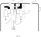
- Fig. 1A is a schematic diagram illustrating a communication antenna according to an example embodiment of the present disclosure.
- the communication antenna is configured to be applied in a mobile terminal with a metal frame.
- the mobile terminal may include but be not limited to a mobile terminal device such as a smart phone, a smart wearable device, a tablet, a personal digital assistant and the like.
- a first break gap 101 and a second break gap 102 are formed at a same side of the metal frame 100 of the mobile terminal. It can be understood that, the first break gap 101 and the second break gap 102 may be formed at any other location of the metal frame 100, which is not limited in embodiments of the present disclosure.
- the first break gap 101 and the second break gap 102 shown in Fig. 1 are illustrated as an example in all the following embodiments of the present disclosure.
- the communication antenna includes a first passive unit 110, a stimulation receiving unit 120 and a second passive unit 130.
- the first passive unit 110 may include a first antenna pattern 111 and a regulating circuit 112.
- the first antenna pattern 111 is disposed around the first break gap 101.
- a first terminal of the first antenna pattern 111 is electrically coupled to the part of the metal frame 103 between the first break gap 101 and the second break gap 102, and a second terminal of the first antenna pattern 111 is provided with a first grounding node 113.
- the first antenna pattern 111 may be electrically coupled to a first terminal of the regulating circuit 112 via the first grounding node 113, and a second terminal of the regulating circuit 112 is coupled to ground.
- the regulating circuit 112 may include a switch, a controller and a regulating assembly.
- the regulating assembly includes a plurality of electronic components, such as a resistor, a capacitor, or an inductor, or the like.
- the controller is configured to control the switch to connect different electronic components of the regulating assembly with the circuit under different communication requirements, so as to make the communication antenna resonated in different frequency ranges.
- Fig. 1B is a schematic diagram illustrating a circuit structure of a regulating circuit according to an example embodiment of the present disclosure.
- the regulating circuit 112 may include a switch 112a, a controller 112b and a regulating assembly 112c.
- the regulating assembly 112c includes a resistor R, a capacitor C, or an inductor L. Every time the switch 112a is able to only connect one of the resistor R, the capacitor C and the inductor L with the circuit.
- Such as a resistance value of the resistor is equal to 0 ⁇ ; a capacitance value of the capacitor is in a range of 0.5 pF to 15 pF; and an inductance value of the inductor is in a range of 1 nH to 22 nH.
- the above communication antenna may meet the communication requirements in a band range of 824 MHz to 894 MHz; under a condition that the capacitor C is connected to the circuit, the above communication antenna may meet the communication requirements in a band range of 880 MHz to 960 MHz; and under a condition that the inductor L is connected to the circuit, the above communication antenna may meet the communication requirements in a band range of 699 MHz to 803 MHz.
- the above resistor with the resistance value of 0 ⁇ may be replaced with a wire or a line, which is not limited in embodiments of the present disclosure.
- the communication frequency bands of the communication antenna is extended, thereby the communication frequency bands of the communication antenna may cover a band range of 700 MHz to 2700 MHz.
- the stimulation receiving unit 120 may include a second antenna pattern 121 and a first matching circuit 122.
- the second antenna pattern 121 is disposed around the first break gap 101.
- a first terminal of the second antenna pattern 121 is electrically coupled to the part of the metal frame 103 between the first break gap 101 and the second break gap 102.
- a feeding node 123 is disposed on the second antenna pattern 121.
- the second antenna pattern 121 may be electrically coupled to a first terminal of the first matching circuit 122 via the feeding node 123, and a second terminal of the first matching circuit 122 is coupled to the radio frequency module, so as to receive an electrical signal transmitted by the radio frequency module.
- the first matching circuit 122 may at least include a first capacitor.
- the first capacitor may be coupled between the feeding node 123 and the radio frequency module.
- the first matching circuit 122 may further include a second capacitor, a first inductor and a second inductor.
- parameter configuration may be performed on the first capacitor, the second capacitor, the first inductor and the second inductor, so that an impedance of the first matching circuit 122 is about 50 ⁇ .
- Fig. 1C is a schematic diagram illustrating a circuit structure of a first matching circuit according to an example embodiment of the present disclosure.
- the first matching circuit includes a first capacitor C1, a second capacitor C2, a first inductor L1 and a second inductor L2.
- a first terminal of the first capacitor C1 is connected to the feeding node 123, and a second terminal of the first capacitor C1 is connected to a first terminal of the second capacitor C2, and a second terminal of the second capacitor C2 is connected to the radio frequency module.
- a first terminal of the first inductor L1 is connected to the feeding node 123, and a second terminal of the first inductor L1 is connected to ground.
- a first terminal of the second inductor L2 is connected to a connecting node of the first capacitor C1 and the second capacitor C2, and a second terminal of the second inductor L2 is connected to ground.
- the second passive unit 130 may include a third antenna pattern 131 and a second matching circuit 132.
- the third antenna pattern 131 is disposed around the first break gap 101.
- a second grounding node 133 is disposed on the third antenna pattern 131.
- the third antenna pattern 131 may be electrically coupled to a first terminal of the second matching circuit 132 via the second grounding node 133, and a second terminal of the second matching circuit 132 is coupled to ground.
- the second matching circuit 132 may include a resistor.
- a first terminal of the resistor may be connected to the second grounding node 133, and a second terminal thereof is connected to ground.
- a resistance value of the resistor may be 0 ⁇ . It should be noted that, the above resistor with the resistance value of 0 ⁇ may be replaced with a wire or a line, which is not limited in embodiments of the present disclosure.
- the feeding node 123 is located between the first grounding node 113 and the second grounding node 133.
- the regulating circuit is disposed in the first passive unit, the regulating circuit includes the switch, the controller and the regulating assembly, the regulating assembly includes the plurality of electronic components, and the controller is configured to control the switch to connect different electronic components of the regulating assembly to the circuit, so as to make the communication antenna resonated in different frequency ranges, thereby extending communication frequency bands of the communication antenna, and further meeting communication requirements in different frequency bands.
- Fig. 2 is a schematic diagram illustrating another communication antenna according to an example embodiment of the present disclosure.
- the communication antenna is configured to be applied in a mobile terminal with a metal frame.
- a first break gap 101 and a second break gap 102 are formed at a same side of the metal frame 100 of the mobile terminal. It can be understood that, the first break gap 101 and the second break gap 102 may be formed at any other location of the metal frame 100, which is not limited in embodiments of the present disclosure.
- the communication antenna includes a first passive unit, a stimulation receiving unit and a second passive unit.
- the stimulation receiving unit may include a second antenna pattern and a first matching circuit.
- the second antenna pattern may include a connecting portion 121a and a feeding portion 121b. Parts of the metal frame at two sides of the first break gap 101 are electrically coupled by the connecting portion 121a.
- the feeding node is disposed on the feeding portion 121b.
- a first parasitic branch 121c is extended from the connecting portion 121a in a first direction.
- a second parasitic branch 121d is extended from the feeding portion 121b in a second direction.
- the first parasitic branch 121c is electrically coupled to the feeding portion 121b.
- a direction indicated by an arrow 201 refers to the first direction, which is a direction from the first break gap to the second break gap from.
- a direction indicated by an arrow 202 refers to the second direction, which is a direction perpendicular to the first direction and pointing to the metal frame.
- the second passive unit may include a third antenna pattern and a second matching circuit.
- the third antenna pattern may include a grounding portion 131 a.
- a second grounding node is disposed on the grounding portion 131a.
- a third parasitic branch 131b is extended from the grounding portion 131a in a direction opposite to the first direction.
- the first parasitic branch 121c extended from the connecting portion 121a may play a role of regulating communication frequency bands of high frequency, thereby improving communication quality of the frequency bands.
- the second parasitic branch 121d extended from the feeding portion 121b may play a role of regulating communication frequency bands of a band range of 2300 MHz to 2400 MHz and a band range of 2500 MHz to 2700 MHz, thereby improving communication quality of the above frequency bands.
- the third parasitic branch 131b extended from the grounding portion 131a may play a role of regulating communication frequency bands of a band range of 1710 MHz to 2170 MHz, thereby improving communication quality of this frequency band.
- the parts of the metal frame at two sides of the first break gap are electrically coupled via the connecting portion of the stimulation receiving unit, the first parasitic branch is extended from the connecting portion of the stimulation receiving unit, and the second parasitic branch is extended from the feeding portion of the stimulation receiving unit, so as to regulate some communication frequency bands, thus improving communication quality of these communication frequency bands.
- the coupling volume of each frequency band may be adjusted by distances among the first antenna pattern, the second antenna pattern and the third antenna pattern, trace thickness, trace length, etc., so that the adjustment of the communication quality of different frequency bands may be realized.
- the first antenna pattern, the second antenna pattern and the third antenna pattern should be separated apart from metal components, such as USB interface, microphone or motor, so as to reduce effects of these metal components on antenna performance.
- metal components such as USB interface, microphone or motor
- Fig. 3 is a flow chart showing a method for controlling a communication antenna according to an example embodiment of the present disclosure. As shown in Fig. 3 , the method is applied in a mobile terminal. The method is based on application of the communication antenna according to embodiments of Fig. 1A and Fig. 2 .
- the mobile terminal may include but be not limited to a mobile terminal device such as a smart phone, a smart wearable device, a tablet, a personal digital assistant and the like.
- the method includes followings.
- a first frequency range is determined where a current communication frequency is located.
- a first electronic component corresponding to the first frequency range is selected from the regulating assembly of the passive unit of the communication antenna and is connected to the circuit, so that the communication antenna is resonated at the first frequency range.
- the frequency band of the terminal communication is wide.
- the frequency band of the communication will become wider. Therefore the communication antenna needs to work in different frequency bands to meet different communication requirements.
- the regulating assembly of the first passive unit of the communication antenna may include a plurality of electronic components, such as a resistor, a capacitor, an inductor and the like.
- the controller of the first passive unit of the communication antenna may control the switch to connect different electronic components of the regulating assembly to the circuit. Different electronic components are connected to the circuit, so that the communication antenna may be resonated in different frequency ranges, and each electronic component may be corresponding to a certain frequency range.
- the communication antenna is resonated in a band range of 824 MHz to 894 MHz; under a condition that the capacitor is connected to the circuit, the communication antenna is resonated in a band range of 880 MHz to 960 MHz; and under a condition that the inductor is connected into the circuit, the communication antenna is resonated in a band range of 699 MHz to 803 MHz.
- Correspondence information of frequency ranges and electronic components is predetermined, for example, the resistor is corresponding to the band range of 824 MHz to 894 MHz, the capacitor is corresponding to the band range of 880 MHz to 960 MHz and the inductor is corresponding to the band range of 699 HMz to 803 MHz. Then the predetermined correspondence information of frequency ranges and electronic components is stored.
- the first frequency range is determined where the current communication frequency is located. For example, when the phone number needs to be dialled via the terminal, the band is determined where the phone communication is. Then, the correspondence information of frequency ranges and electronic components is acquired from pre-stored data. The electronic component corresponding to the first frequency range is found out from the correspondence information and to be used as the first electronic component. The first electronic component is connected to the circuit via the switch, so that the communication antenna may meet the requirements of the telephone communication.
- the first frequency range is determined where the current communication frequency is located, and then the first electronic component corresponding to the first frequency range is selected from the regulating assembly of the first passive unit of the communication antenna and connected to the circuit, so that the communication antenna is resonated in the first frequency range.
- Communication frequency bands of the communication antenna are extended, thereby meeting communication requirements of the current communication.
- embodiments of an apparatus for controlling a communication antenna and a terminal applying the apparatus are also provided by the present disclosure.
- Fig. 4 is a block diagram illustrating an apparatus for controlling a communication antenna according to an example embodiment of the present disclosure. As shown in Fig. 4 , the apparatus is based on application of the communication antenna according to embodiments of Fig. 1A and Fig. 2 .
- the apparatus includes a determining module 401 and a switching module 402.
- the determining module 401 is configured to determine a first frequency range where a current communication frequency is located.
- the switching module 402 is configured to select a first electronic component corresponding to the first frequency range from the regulating assembly of the first passive unit of the communication antenna and connect the first electronic component to the circuit, so that the communication antenna is resonated in the first frequency range.
- Fig. 5 is a block diagram illustrating another apparatus for controlling a communication antenna according to an example embodiment of the present disclosure.
- the switching module 402 includes an acquiring sub module 501, a searching sub module 502 and a connecting sub module 503.
- the acquiring sub module 501 is configured to acquire correspondence information of frequency ranges and electronic components from pre-stored data.
- the searching sub module 502 is configured to search for the first electronic component corresponding to the first frequency range in the correspondence information.
- the connecting sub module 503 is configured to connect the first electronic component to the circuit via the switch.
- the apparatus may be set in advance in the terminal, and may also be downloaded and loaded into the terminal. Corresponding modules in the apparatus may be cooperated with modules in the terminal to achieve a control scheme of the communication antenna.
- contents of the apparatus embodiments related to the device embodiments may also refer to the method embodiments.
- the above-described apparatus embodiments are merely illustrative, in which a unit described as a separate component may or may not be physically separated, a component displayed as a unit may or may not be a physical unit, i.e. may be located at one place, or may be distributed on multiple network units. A part or all of the modules may be selected according to practical needs so as to achieve the object of the solution of the present disclosure, which may be understood and implemented by those skilled in the art without creative labor.
- inventions of the present disclosure also provide a terminal.
- the terminal includes a processor; and a memory configured to store an instruction executable by the processor.
- the processor is configured to:
- Fig. 6 is a schematic diagram illustrating a device 2100 for controlling a communication antenna according to an example embodiment of the present disclosure.
- the device 2100 may be a mobile phone, a computer, a digital broadcasting terminal, a messaging device, a game console, a tablet device, a fitness equipment, a medical device, a Personal Digital Assistant PDA, etc.
- the device 2100 may include the following one or more components: a processing component 2102, a memory 2104, a power component 2106, a multimedia component 2108, an audio component 2110, an Input/Output (I/O) interface 2112, a sensor component 2114, and a communication component 2116.
- the processing component 2102 typically controls overall operations of the device 2100, such as the operations associated with display, telephone calls, data communications, camera operations, and recording operations.
- the processing component 2102 may include one or more processors 2120 to execute instructions to perform all or part of the blocks in the above described methods.
- the processing component 2102 may include one or more modules which facilitate the interaction between the processing component 2102 and other components.
- the processing component 2102 may include a multimedia module to facilitate the interaction between the multimedia component 2108 and the processing component 2102.
- the memory 2104 is configured to store various types of data to support the operation of the device 2100. Examples of such data include instructions for any applications or methods operated on the device 2100, contact data, phonebook data, messages, pictures, video, etc.
- the memory 2104 may be implemented using any type of volatile or non-volatile memory devices, or a combination thereof, such as a static random access memory (SRAM), an electrically erasable programmable read-only memory (EEPROM), an erasable programmable read-only memory (EPROM), a programmable read-only memory (PROM), a read-only memory (ROM), a magnetic memory, a flash memory, a magnetic or optical disk.
- SRAM static random access memory
- EEPROM electrically erasable programmable read-only memory
- EPROM erasable programmable read-only memory
- PROM programmable read-only memory
- ROM read-only memory
- magnetic memory a magnetic memory
- flash memory a flash memory
- magnetic or optical disk a magnetic
- the power component 2106 provides power to various components of the device 2100.
- the power component 2106 may include a power management system, one or more power sources, and any other components associated with the generation, management, and distribution of power in the device 2100.
- the multimedia component 2108 includes a screen providing an output interface between the device 2100 and the user.
- the screen may include a liquid crystal display (LCD) and a press panel (TP). If the screen includes the press panel, the screen may be implemented as a press screen to receive input signals from the user.
- the press panel includes one or more press sensors to sense presses, swipes, and other gestures on the press panel. The press sensors may not only sense a boundary of a press or swipe action, but also sense a duration time and a pressure associated with the press or swipe action.
- the multimedia component 2108 includes a front camera and/or a rear camera. The front camera and/or the rear camera may receive external multimedia data while the device 2100 is in an operation mode, such as a photographing mode or a video mode. Each of the front camera and the rear camera may be a fixed optical lens system or have focus and optical zoom capability.
- the audio component 2110 is configured to output and/or input audio signals.
- the audio component 2110 includes a microphone (MIC) configured to receive an external audio signal when the device 2100 is in an operation mode, such as a call mode, a recording mode, and a voice recognition mode.
- the received audio signal may be further stored in the memory 2104 or transmitted via the communication component 2116.
- the audio component 2110 further includes a speaker to output audio signals.
- the I/O interface 2112 provides an interface for the processing component 2102 and peripheral interface modules, such as a keyboard, a click wheel, buttons, and the like.
- the buttons may include, but are not limited to, a home button, a volume button, a starting button, and a locking button.
- the sensor component 2114 includes one or more sensors to provide status assessments of various aspects of the device 2100. For instance, the sensor component 2114 may detect an open/closed status of the device 2100 and relative positioning of components (e.g. the display and the keypad of the device 2100). The sensor component 2114 may also detect a change in position of the device 2100 or of a component in the device 2100, a presence or absence of user contact with the device 2100, an orientation or an acceleration/deceleration of the device 2100, and a change in temperature of the device 2100. The sensor component 2114 may include a proximity sensor configured to detect the presence of nearby objects without any physical contact.
- the sensor component 2114 may also include a light sensor, such as a CMOS or CCD image sensor, for use in imaging applications.
- the sensor component 2114 may also include an accelerometer sensor, a gyroscope sensor, a magnetic sensor, a pressure sensor, or a temperature sensor.
- the communication component 2116 is configured to facilitate wired or wireless communication between the device 2100 and other devices.
- the device 2100 can access a wireless network based on a communication standard, such as WIFI, 2G, or 3G, or a combination thereof.
- the communication component 2116 receives a broadcast signal or broadcast associated information from an external broadcast management system via a broadcast channel.
- the communication component 2116 further includes a near field communication (NFC) module to facilitate short-range communications.
- the NFC module may be implemented based on a radio frequency identification (RFID) technology, an infrared data association (IrDA) technology, an ultra-wideband (UWB) technology, a Bluetooth (BT) technology, and other technologies.
- RFID radio frequency identification
- IrDA infrared data association
- UWB ultra-wideband
- BT Bluetooth
- the device 2100 may be implemented with one or more application specific integrated circuits (ASICs), digital signal processors (DSPs), digital signal processing devices (DSPDs), programmable logic devices (PLDs), field programmable gate arrays (FPGAs), controllers, micro-controllers, microprocessors, or other electronic components, for performing the above described methods.
- ASICs application specific integrated circuits
- DSPs digital signal processors
- DSPDs digital signal processing devices
- PLDs programmable logic devices
- FPGAs field programmable gate arrays
- controllers micro-controllers, microprocessors, or other electronic components, for performing the above described methods.
- a non-transitory computer readable storage medium including instructions, such as the memory 2104 including instructions.
- the above instructions are executable by the processor 2120 in the device 2100, for performing the above-described methods.
- the non-transitory computer-readable storage medium may be a ROM, a RAM, a CD-ROM, a magnetic tape, a floppy disc, an optical data storage device, and the like.
- Other embodiments of the invention will be apparent to those skilled in the art from consideration of the specification and practice of the invention disclosed here. This application is intended to cover any variations, uses, or adaptations of the invention following the general principles thereof and including such departures from the present disclosure as come within known or customary practice in the art.
Landscapes
- Engineering & Computer Science (AREA)
- Computer Networks & Wireless Communication (AREA)
- Signal Processing (AREA)
- Support Of Aerials (AREA)
- Transceivers (AREA)
Applications Claiming Priority (1)
| Application Number | Priority Date | Filing Date | Title |
|---|---|---|---|
| CN201610371760.2A CN105977614B (zh) | 2016-05-30 | 2016-05-30 | 通信天线、通信天线的控制方法、装置及终端 |
Publications (2)
| Publication Number | Publication Date |
|---|---|
| EP3252868A1 true EP3252868A1 (de) | 2017-12-06 |
| EP3252868B1 EP3252868B1 (de) | 2019-03-20 |
Family
ID=57009826
Family Applications (1)
| Application Number | Title | Priority Date | Filing Date |
|---|---|---|---|
| EP16200574.8A Active EP3252868B1 (de) | 2016-05-30 | 2016-11-24 | Kommunikationsantenne, verfahren und vorrichtung zur steuerung davon und endgerät |
Country Status (4)
| Country | Link |
|---|---|
| US (1) | US10177443B2 (de) |
| EP (1) | EP3252868B1 (de) |
| CN (1) | CN105977614B (de) |
| WO (1) | WO2017206367A1 (de) |
Families Citing this family (38)
| Publication number | Priority date | Publication date | Assignee | Title |
|---|---|---|---|---|
| CN108023183B (zh) * | 2016-10-31 | 2022-01-04 | 北京小米移动软件有限公司 | 移动终端的天线结构及移动终端 |
| CN108123210B (zh) * | 2016-11-26 | 2020-07-28 | 北京小米移动软件有限公司 | 终端的天线 |
| CN108232412B (zh) * | 2016-12-09 | 2020-04-03 | 深圳富泰宏精密工业有限公司 | 天线结构及具有该天线结构的无线通信装置 |
| CN106450669B (zh) * | 2016-12-15 | 2019-09-17 | 奇酷互联网络科技(深圳)有限公司 | 移动终端及其天线装置 |
| CN106876891A (zh) * | 2016-12-29 | 2017-06-20 | 努比亚技术有限公司 | 一种天线、移动终端和其控制方法 |
| CN108539387A (zh) * | 2017-03-03 | 2018-09-14 | 北京小米移动软件有限公司 | 电子设备的天线模组和电子设备 |
| KR102208890B1 (ko) * | 2017-03-20 | 2021-01-27 | 후아웨이 테크놀러지 컴퍼니 리미티드 | 이동 단말기의 안테나와 이동 단말기 |
| EP3616259B1 (de) | 2017-05-12 | 2023-10-25 | Huawei Technologies Co., Ltd. | Kommunikationsvorrichtung |
| CN113571882B (zh) * | 2017-05-12 | 2023-02-03 | 华为技术有限公司 | 一种通信设备 |
| CN107331964A (zh) * | 2017-06-26 | 2017-11-07 | 北京小米移动软件有限公司 | 金属边框终端天线和终端 |
| TWI643397B (zh) * | 2017-08-22 | 2018-12-01 | 廣達電腦股份有限公司 | 行動裝置 |
| US10700416B2 (en) * | 2017-08-30 | 2020-06-30 | Lg Electronics Inc. | Mobile terminal |
| TWI648907B (zh) * | 2017-09-04 | 2019-01-21 | 廣達電腦股份有限公司 | 行動裝置 |
| JP2019050316A (ja) * | 2017-09-11 | 2019-03-28 | 東芝メモリ株式会社 | Sem検査装置およびパターンマッチング方法 |
| CN107834206B (zh) * | 2017-10-27 | 2020-07-21 | 北京小米移动软件有限公司 | 一种天线及移动终端 |
| CN109980333A (zh) * | 2017-12-27 | 2019-07-05 | 深圳富泰宏精密工业有限公司 | 天线结构及具有该天线结构的无线通信装置 |
| CN108258382B (zh) * | 2017-12-29 | 2020-09-18 | 瑞声科技(新加坡)有限公司 | 一种天线系统 |
| CN108336483B (zh) * | 2018-02-02 | 2021-03-02 | Oppo广东移动通信有限公司 | 天线组件、电子设备及天线切换方法 |
| CN108511905B (zh) * | 2018-04-19 | 2021-03-02 | Oppo广东移动通信有限公司 | 天线系统和移动终端 |
| EP3767742B1 (de) * | 2018-05-08 | 2023-11-22 | Huawei Technologies Co., Ltd. | Antennenvorrichtung und mobiles endgerät |
| CN108598666B (zh) * | 2018-05-28 | 2020-11-13 | 北京小米移动软件有限公司 | 终端壳体及终端 |
| CN108832272B (zh) * | 2018-05-29 | 2020-08-21 | 北京小米移动软件有限公司 | 电子设备及其天线结构 |
| CN110556620B (zh) * | 2018-06-01 | 2021-07-09 | 华为技术有限公司 | 天线及移动终端 |
| CN113629377B (zh) * | 2018-07-23 | 2023-11-10 | Oppo广东移动通信有限公司 | 天线组件及电子设备 |
| CN108987908B (zh) * | 2018-07-27 | 2021-05-18 | 北京小米移动软件有限公司 | 一种天线及移动终端 |
| CN109088148A (zh) * | 2018-08-26 | 2018-12-25 | 昆山亿趣信息技术研究院有限公司 | 一种高频手机天线 |
| CN109193129B (zh) | 2018-08-31 | 2021-04-27 | 北京小米移动软件有限公司 | 天线系统及终端 |
| CN111146570B (zh) * | 2018-11-02 | 2022-08-23 | 青岛海信移动通信技术股份有限公司 | 一种具有可重构天线的终端 |
| CN111261998A (zh) * | 2018-11-30 | 2020-06-09 | 北京小米移动软件有限公司 | 天线及具有其的终端设备 |
| CN109742512A (zh) * | 2018-12-24 | 2019-05-10 | 瑞声科技(南京)有限公司 | 天线模组及移动终端 |
| CN109728406B (zh) * | 2018-12-24 | 2021-07-02 | 瑞声精密制造科技(常州)有限公司 | 天线系统及电子设备 |
| WO2021045240A1 (ko) * | 2019-09-03 | 2021-03-11 | 엘지전자 주식회사 | 안테나 및 이를 구비하는 전자 기기 |
| CN113675592B (zh) * | 2020-05-13 | 2023-08-04 | 北京小米移动软件有限公司 | 一种天线模组和终端设备 |
| CN111786696A (zh) * | 2020-07-13 | 2020-10-16 | 维沃移动通信有限公司 | 天线调节方法、电路、装置和电子设备 |
| CN112531321B (zh) * | 2020-11-27 | 2022-05-06 | 捷开通讯(深圳)有限公司 | 天线组件及移动终端 |
| CN112768875B (zh) * | 2020-12-25 | 2023-07-25 | Oppo广东移动通信有限公司 | 电子设备 |
| CN115693094A (zh) * | 2021-07-30 | 2023-02-03 | 维沃移动通信有限公司 | 电子设备 |
| CN113629394A (zh) * | 2021-08-31 | 2021-11-09 | 山东炎一智能科技有限公司 | 用于天线中心频点频率调整的方法及装置 |
Citations (4)
| Publication number | Priority date | Publication date | Assignee | Title |
|---|---|---|---|---|
| CN103296385A (zh) * | 2013-05-29 | 2013-09-11 | 上海安费诺永亿通讯电子有限公司 | 一种可调式多频天线系统 |
| US20140323063A1 (en) * | 2013-04-26 | 2014-10-30 | Apple Inc. | Methods for Manufacturing an Antenna Tuning Element in an Electronic Device |
| CN105305067A (zh) * | 2015-10-29 | 2016-02-03 | 维沃移动通信有限公司 | 一种天线系统及移动终端 |
| US20160064801A1 (en) * | 2014-09-03 | 2016-03-03 | Apple Inc. | Electronic Device Antenna With Reduced Lossy Mode |
Family Cites Families (29)
| Publication number | Priority date | Publication date | Assignee | Title |
|---|---|---|---|---|
| US5815804A (en) * | 1997-04-17 | 1998-09-29 | Motorola | Dual-band filter network |
| US5969582A (en) * | 1997-07-03 | 1999-10-19 | Ericsson Inc. | Impedance matching circuit for power amplifier |
| US6188877B1 (en) | 1997-07-03 | 2001-02-13 | Ericsson Inc. | Dual-band, dual-mode power amplifier with reduced power loss |
| US6298244B1 (en) | 1997-07-03 | 2001-10-02 | Ericsson Inc. | Dual-band, dual-mode power amplifier |
| JP4044302B2 (ja) * | 2001-06-20 | 2008-02-06 | 株式会社村田製作所 | 表面実装型アンテナおよびそれを用いた無線機 |
| US7696928B2 (en) * | 2006-02-08 | 2010-04-13 | Hong Kong Applied Science And Technology Research Institute Co., Ltd. | Systems and methods for using parasitic elements for controlling antenna resonances |
| JP2008278219A (ja) * | 2007-04-27 | 2008-11-13 | Toshiba Corp | アンテナ装置 |
| US9941588B2 (en) * | 2007-08-20 | 2018-04-10 | Ethertronics, Inc. | Antenna with multiple coupled regions |
| FI20096134A0 (fi) * | 2009-11-03 | 2009-11-03 | Pulse Finland Oy | Säädettävä antenni |
| CN101714689A (zh) * | 2009-12-21 | 2010-05-26 | 徐锋 | 用于手持通讯设备的内置天线 |
| CN102804490A (zh) * | 2010-03-31 | 2012-11-28 | 日本电气株式会社 | 便携式无线装置 |
| CN101873382B (zh) * | 2010-06-30 | 2014-10-22 | 深圳市经纬科技有限公司 | 一种手机及其电视内置天线动态调谐方法和装置 |
| US20130010842A1 (en) * | 2011-07-05 | 2013-01-10 | Broadcom Corporation | Programmable multiple interwoven spiral antenna assembly |
| US9306276B2 (en) * | 2011-07-13 | 2016-04-05 | Qualcomm Incorporated | Wideband antenna system with multiple antennas and at least one parasitic element |
| US9325064B2 (en) * | 2011-08-18 | 2016-04-26 | Sony Corporation | Mobile terminal |
| DK2640094T3 (en) | 2012-03-13 | 2016-02-29 | Bernafon Ag | Hearing and detection device |
| CN103094717B (zh) * | 2013-02-19 | 2017-02-15 | 魅族科技(中国)有限公司 | 一种终端设备的天线和终端设备 |
| WO2014142411A1 (ko) * | 2013-03-15 | 2014-09-18 | 엘지전자 주식회사 | 안테나 모듈 및 이를 구비하는 이동 단말기 |
| EP3032646B1 (de) * | 2013-08-06 | 2018-10-10 | LG Electronics Inc. | Antennenvorrichtung und mobiles endgerät damit |
| KR102102644B1 (ko) * | 2013-12-24 | 2020-04-21 | 엘지전자 주식회사 | 이동 단말기 |
| CN104810605B (zh) * | 2014-01-23 | 2018-02-02 | 维沃移动通信有限公司 | 一种分开耦合馈入的天线装置 |
| CN203895602U (zh) * | 2014-06-05 | 2014-10-22 | 上海安费诺永亿通讯电子有限公司 | 新型环形天线装置 |
| US10008775B2 (en) * | 2014-06-30 | 2018-06-26 | Intel IP Corporation | Antenna configuration with a coupler element for wireless communication |
| CN105576349A (zh) * | 2014-10-15 | 2016-05-11 | 深圳富泰宏精密工业有限公司 | 天线结构及具有该天线结构的无线通信装置 |
| US20160112551A1 (en) * | 2015-01-06 | 2016-04-21 | Mediatek Inc. | Metal-Frame Slot Antenna With Matching Circuit And Apparatus Thereof |
| CN104577334B (zh) * | 2015-02-11 | 2017-07-21 | 小米科技有限责任公司 | 天线模块及移动终端 |
| CN204681375U (zh) * | 2015-05-20 | 2015-09-30 | 上海与德通讯技术有限公司 | 一种射频前端电路 |
| CN108321542B (zh) * | 2015-06-12 | 2020-08-21 | Oppo广东移动通信有限公司 | 天线系统及应用该天线系统的通信终端 |
| CN107240765B (zh) * | 2016-03-29 | 2019-12-13 | 北京小米移动软件有限公司 | 一种wifi天线 |
-
2016
- 2016-05-30 CN CN201610371760.2A patent/CN105977614B/zh active Active
- 2016-08-17 WO PCT/CN2016/095644 patent/WO2017206367A1/zh active Application Filing
- 2016-11-24 EP EP16200574.8A patent/EP3252868B1/de active Active
- 2016-12-14 US US15/378,635 patent/US10177443B2/en active Active
Patent Citations (4)
| Publication number | Priority date | Publication date | Assignee | Title |
|---|---|---|---|---|
| US20140323063A1 (en) * | 2013-04-26 | 2014-10-30 | Apple Inc. | Methods for Manufacturing an Antenna Tuning Element in an Electronic Device |
| CN103296385A (zh) * | 2013-05-29 | 2013-09-11 | 上海安费诺永亿通讯电子有限公司 | 一种可调式多频天线系统 |
| US20160064801A1 (en) * | 2014-09-03 | 2016-03-03 | Apple Inc. | Electronic Device Antenna With Reduced Lossy Mode |
| CN105305067A (zh) * | 2015-10-29 | 2016-02-03 | 维沃移动通信有限公司 | 一种天线系统及移动终端 |
Also Published As
| Publication number | Publication date |
|---|---|
| CN105977614B (zh) | 2020-02-07 |
| US10177443B2 (en) | 2019-01-08 |
| US20170346159A1 (en) | 2017-11-30 |
| CN105977614A (zh) | 2016-09-28 |
| WO2017206367A1 (zh) | 2017-12-07 |
| EP3252868B1 (de) | 2019-03-20 |
Similar Documents
| Publication | Publication Date | Title |
|---|---|---|
| EP3252868B1 (de) | Kommunikationsantenne, verfahren und vorrichtung zur steuerung davon und endgerät | |
| US10186755B2 (en) | Antenna module and mobile terminal using the same | |
| KR101622731B1 (ko) | 이동 단말기 | |
| US10680330B2 (en) | Antenna and electronic device | |
| US10998610B2 (en) | Electronic device, method for adjusting operating frequency band of antenna of electronic device | |
| CN107026314B (zh) | 移动终端的天线 | |
| CN107196042B (zh) | 天线模块、终端和电子设备 | |
| CN107453034B (zh) | 一种用于终端设备的天线 | |
| US9961173B2 (en) | Antenna and mobile terminal including the same | |
| CN108598683B (zh) | 天线组件及终端 | |
| CN106229627B (zh) | 一种天线组件和移动终端 | |
| US10490884B2 (en) | Metal cover and electronic device | |
| CN109346852B (zh) | 天线模组、电子设备 | |
| CN107369923B (zh) | 天线组件及终端 | |
| CN108270069B (zh) | 天线模组和电子设备 | |
| CN111384582A (zh) | 天线组件以及移动终端 | |
| CN110620289A (zh) | 射频装置及终端设备 | |
| CN111509365B (zh) | 天线组件以及移动终端 | |
| EP3761444A1 (de) | Endgerät | |
| CN107171054B (zh) | 天线装置及终端 | |
| KR20160141426A (ko) | 휴대용 액세서리 장치 | |
| CN108123211B (zh) | 终端天线系统及控制终端天线系统辐射频段的方法和装置 | |
| CN107994318B (zh) | 天线模组和电子设备 | |
| CN118099710A (zh) | 一种电子设备 | |
| CN118099711A (zh) | 一种电子设备 |
Legal Events
| Date | Code | Title | Description |
|---|---|---|---|
| PUAI | Public reference made under article 153(3) epc to a published international application that has entered the european phase |
Free format text: ORIGINAL CODE: 0009012 |
|
| STAA | Information on the status of an ep patent application or granted ep patent |
Free format text: STATUS: THE APPLICATION HAS BEEN PUBLISHED |
|
| AK | Designated contracting states |
Kind code of ref document: A1 Designated state(s): AL AT BE BG CH CY CZ DE DK EE ES FI FR GB GR HR HU IE IS IT LI LT LU LV MC MK MT NL NO PL PT RO RS SE SI SK SM TR |
|
| AX | Request for extension of the european patent |
Extension state: BA ME |
|
| STAA | Information on the status of an ep patent application or granted ep patent |
Free format text: STATUS: REQUEST FOR EXAMINATION WAS MADE |
|
| 17P | Request for examination filed |
Effective date: 20180604 |
|
| RBV | Designated contracting states (corrected) |
Designated state(s): AL AT BE BG CH CY CZ DE DK EE ES FI FR GB GR HR HU IE IS IT LI LT LU LV MC MK MT NL NO PL PT RO RS SE SI SK SM TR |
|
| GRAP | Despatch of communication of intention to grant a patent |
Free format text: ORIGINAL CODE: EPIDOSNIGR1 |
|
| STAA | Information on the status of an ep patent application or granted ep patent |
Free format text: STATUS: GRANT OF PATENT IS INTENDED |
|
| INTG | Intention to grant announced |
Effective date: 20181023 |
|
| GRAS | Grant fee paid |
Free format text: ORIGINAL CODE: EPIDOSNIGR3 |
|
| GRAA | (expected) grant |
Free format text: ORIGINAL CODE: 0009210 |
|
| STAA | Information on the status of an ep patent application or granted ep patent |
Free format text: STATUS: THE PATENT HAS BEEN GRANTED |
|
| AK | Designated contracting states |
Kind code of ref document: B1 Designated state(s): AL AT BE BG CH CY CZ DE DK EE ES FI FR GB GR HR HU IE IS IT LI LT LU LV MC MK MT NL NO PL PT RO RS SE SI SK SM TR |
|
| REG | Reference to a national code |
Ref country code: GB Ref legal event code: FG4D |
|
| REG | Reference to a national code |
Ref country code: CH Ref legal event code: EP |
|
| REG | Reference to a national code |
Ref country code: DE Ref legal event code: R096 Ref document number: 602016011247 Country of ref document: DE |
|
| REG | Reference to a national code |
Ref country code: AT Ref legal event code: REF Ref document number: 1111460 Country of ref document: AT Kind code of ref document: T Effective date: 20190415 |
|
| REG | Reference to a national code |
Ref country code: IE Ref legal event code: FG4D |
|
| REG | Reference to a national code |
Ref country code: NL Ref legal event code: MP Effective date: 20190320 |
|
| PG25 | Lapsed in a contracting state [announced via postgrant information from national office to epo] |
Ref country code: LT Free format text: LAPSE BECAUSE OF FAILURE TO SUBMIT A TRANSLATION OF THE DESCRIPTION OR TO PAY THE FEE WITHIN THE PRESCRIBED TIME-LIMIT Effective date: 20190320 Ref country code: NO Free format text: LAPSE BECAUSE OF FAILURE TO SUBMIT A TRANSLATION OF THE DESCRIPTION OR TO PAY THE FEE WITHIN THE PRESCRIBED TIME-LIMIT Effective date: 20190620 Ref country code: FI Free format text: LAPSE BECAUSE OF FAILURE TO SUBMIT A TRANSLATION OF THE DESCRIPTION OR TO PAY THE FEE WITHIN THE PRESCRIBED TIME-LIMIT Effective date: 20190320 Ref country code: SE Free format text: LAPSE BECAUSE OF FAILURE TO SUBMIT A TRANSLATION OF THE DESCRIPTION OR TO PAY THE FEE WITHIN THE PRESCRIBED TIME-LIMIT Effective date: 20190320 |
|
| REG | Reference to a national code |
Ref country code: LT Ref legal event code: MG4D |
|
| PG25 | Lapsed in a contracting state [announced via postgrant information from national office to epo] |
Ref country code: HR Free format text: LAPSE BECAUSE OF FAILURE TO SUBMIT A TRANSLATION OF THE DESCRIPTION OR TO PAY THE FEE WITHIN THE PRESCRIBED TIME-LIMIT Effective date: 20190320 Ref country code: RS Free format text: LAPSE BECAUSE OF FAILURE TO SUBMIT A TRANSLATION OF THE DESCRIPTION OR TO PAY THE FEE WITHIN THE PRESCRIBED TIME-LIMIT Effective date: 20190320 Ref country code: BG Free format text: LAPSE BECAUSE OF FAILURE TO SUBMIT A TRANSLATION OF THE DESCRIPTION OR TO PAY THE FEE WITHIN THE PRESCRIBED TIME-LIMIT Effective date: 20190620 Ref country code: GR Free format text: LAPSE BECAUSE OF FAILURE TO SUBMIT A TRANSLATION OF THE DESCRIPTION OR TO PAY THE FEE WITHIN THE PRESCRIBED TIME-LIMIT Effective date: 20190621 Ref country code: LV Free format text: LAPSE BECAUSE OF FAILURE TO SUBMIT A TRANSLATION OF THE DESCRIPTION OR TO PAY THE FEE WITHIN THE PRESCRIBED TIME-LIMIT Effective date: 20190320 Ref country code: NL Free format text: LAPSE BECAUSE OF FAILURE TO SUBMIT A TRANSLATION OF THE DESCRIPTION OR TO PAY THE FEE WITHIN THE PRESCRIBED TIME-LIMIT Effective date: 20190320 |
|
| REG | Reference to a national code |
Ref country code: AT Ref legal event code: MK05 Ref document number: 1111460 Country of ref document: AT Kind code of ref document: T Effective date: 20190320 |
|
| PG25 | Lapsed in a contracting state [announced via postgrant information from national office to epo] |
Ref country code: EE Free format text: LAPSE BECAUSE OF FAILURE TO SUBMIT A TRANSLATION OF THE DESCRIPTION OR TO PAY THE FEE WITHIN THE PRESCRIBED TIME-LIMIT Effective date: 20190320 Ref country code: SK Free format text: LAPSE BECAUSE OF FAILURE TO SUBMIT A TRANSLATION OF THE DESCRIPTION OR TO PAY THE FEE WITHIN THE PRESCRIBED TIME-LIMIT Effective date: 20190320 Ref country code: ES Free format text: LAPSE BECAUSE OF FAILURE TO SUBMIT A TRANSLATION OF THE DESCRIPTION OR TO PAY THE FEE WITHIN THE PRESCRIBED TIME-LIMIT Effective date: 20190320 Ref country code: PT Free format text: LAPSE BECAUSE OF FAILURE TO SUBMIT A TRANSLATION OF THE DESCRIPTION OR TO PAY THE FEE WITHIN THE PRESCRIBED TIME-LIMIT Effective date: 20190720 Ref country code: CZ Free format text: LAPSE BECAUSE OF FAILURE TO SUBMIT A TRANSLATION OF THE DESCRIPTION OR TO PAY THE FEE WITHIN THE PRESCRIBED TIME-LIMIT Effective date: 20190320 Ref country code: RO Free format text: LAPSE BECAUSE OF FAILURE TO SUBMIT A TRANSLATION OF THE DESCRIPTION OR TO PAY THE FEE WITHIN THE PRESCRIBED TIME-LIMIT Effective date: 20190320 Ref country code: AL Free format text: LAPSE BECAUSE OF FAILURE TO SUBMIT A TRANSLATION OF THE DESCRIPTION OR TO PAY THE FEE WITHIN THE PRESCRIBED TIME-LIMIT Effective date: 20190320 Ref country code: IT Free format text: LAPSE BECAUSE OF FAILURE TO SUBMIT A TRANSLATION OF THE DESCRIPTION OR TO PAY THE FEE WITHIN THE PRESCRIBED TIME-LIMIT Effective date: 20190320 |
|
| PG25 | Lapsed in a contracting state [announced via postgrant information from national office to epo] |
Ref country code: PL Free format text: LAPSE BECAUSE OF FAILURE TO SUBMIT A TRANSLATION OF THE DESCRIPTION OR TO PAY THE FEE WITHIN THE PRESCRIBED TIME-LIMIT Effective date: 20190320 Ref country code: SM Free format text: LAPSE BECAUSE OF FAILURE TO SUBMIT A TRANSLATION OF THE DESCRIPTION OR TO PAY THE FEE WITHIN THE PRESCRIBED TIME-LIMIT Effective date: 20190320 |
|
| PG25 | Lapsed in a contracting state [announced via postgrant information from national office to epo] |
Ref country code: AT Free format text: LAPSE BECAUSE OF FAILURE TO SUBMIT A TRANSLATION OF THE DESCRIPTION OR TO PAY THE FEE WITHIN THE PRESCRIBED TIME-LIMIT Effective date: 20190320 Ref country code: IS Free format text: LAPSE BECAUSE OF FAILURE TO SUBMIT A TRANSLATION OF THE DESCRIPTION OR TO PAY THE FEE WITHIN THE PRESCRIBED TIME-LIMIT Effective date: 20190720 |
|
| REG | Reference to a national code |
Ref country code: DE Ref legal event code: R097 Ref document number: 602016011247 Country of ref document: DE |
|
| PLBE | No opposition filed within time limit |
Free format text: ORIGINAL CODE: 0009261 |
|
| STAA | Information on the status of an ep patent application or granted ep patent |
Free format text: STATUS: NO OPPOSITION FILED WITHIN TIME LIMIT |
|
| PG25 | Lapsed in a contracting state [announced via postgrant information from national office to epo] |
Ref country code: DK Free format text: LAPSE BECAUSE OF FAILURE TO SUBMIT A TRANSLATION OF THE DESCRIPTION OR TO PAY THE FEE WITHIN THE PRESCRIBED TIME-LIMIT Effective date: 20190320 |
|
| 26N | No opposition filed |
Effective date: 20200102 |
|
| PG25 | Lapsed in a contracting state [announced via postgrant information from national office to epo] |
Ref country code: SI Free format text: LAPSE BECAUSE OF FAILURE TO SUBMIT A TRANSLATION OF THE DESCRIPTION OR TO PAY THE FEE WITHIN THE PRESCRIBED TIME-LIMIT Effective date: 20190320 |
|
| PG25 | Lapsed in a contracting state [announced via postgrant information from national office to epo] |
Ref country code: TR Free format text: LAPSE BECAUSE OF FAILURE TO SUBMIT A TRANSLATION OF THE DESCRIPTION OR TO PAY THE FEE WITHIN THE PRESCRIBED TIME-LIMIT Effective date: 20190320 |
|
| REG | Reference to a national code |
Ref country code: CH Ref legal event code: PL |
|
| PG25 | Lapsed in a contracting state [announced via postgrant information from national office to epo] |
Ref country code: LU Free format text: LAPSE BECAUSE OF NON-PAYMENT OF DUE FEES Effective date: 20191124 Ref country code: MC Free format text: LAPSE BECAUSE OF FAILURE TO SUBMIT A TRANSLATION OF THE DESCRIPTION OR TO PAY THE FEE WITHIN THE PRESCRIBED TIME-LIMIT Effective date: 20190320 Ref country code: LI Free format text: LAPSE BECAUSE OF NON-PAYMENT OF DUE FEES Effective date: 20191130 Ref country code: CH Free format text: LAPSE BECAUSE OF NON-PAYMENT OF DUE FEES Effective date: 20191130 |
|
| REG | Reference to a national code |
Ref country code: BE Ref legal event code: MM Effective date: 20191130 |
|
| PG25 | Lapsed in a contracting state [announced via postgrant information from national office to epo] |
Ref country code: IE Free format text: LAPSE BECAUSE OF NON-PAYMENT OF DUE FEES Effective date: 20191124 |
|
| PG25 | Lapsed in a contracting state [announced via postgrant information from national office to epo] |
Ref country code: BE Free format text: LAPSE BECAUSE OF NON-PAYMENT OF DUE FEES Effective date: 20191130 |
|
| PG25 | Lapsed in a contracting state [announced via postgrant information from national office to epo] |
Ref country code: CY Free format text: LAPSE BECAUSE OF FAILURE TO SUBMIT A TRANSLATION OF THE DESCRIPTION OR TO PAY THE FEE WITHIN THE PRESCRIBED TIME-LIMIT Effective date: 20190320 |
|
| PG25 | Lapsed in a contracting state [announced via postgrant information from national office to epo] |
Ref country code: MT Free format text: LAPSE BECAUSE OF FAILURE TO SUBMIT A TRANSLATION OF THE DESCRIPTION OR TO PAY THE FEE WITHIN THE PRESCRIBED TIME-LIMIT Effective date: 20190320 Ref country code: HU Free format text: LAPSE BECAUSE OF FAILURE TO SUBMIT A TRANSLATION OF THE DESCRIPTION OR TO PAY THE FEE WITHIN THE PRESCRIBED TIME-LIMIT; INVALID AB INITIO Effective date: 20161124 |
|
| PG25 | Lapsed in a contracting state [announced via postgrant information from national office to epo] |
Ref country code: MK Free format text: LAPSE BECAUSE OF FAILURE TO SUBMIT A TRANSLATION OF THE DESCRIPTION OR TO PAY THE FEE WITHIN THE PRESCRIBED TIME-LIMIT Effective date: 20190320 |
|
| P01 | Opt-out of the competence of the unified patent court (upc) registered |
Effective date: 20230523 |
|
| PGFP | Annual fee paid to national office [announced via postgrant information from national office to epo] |
Ref country code: GB Payment date: 20231123 Year of fee payment: 8 |
|
| PGFP | Annual fee paid to national office [announced via postgrant information from national office to epo] |
Ref country code: FR Payment date: 20231120 Year of fee payment: 8 Ref country code: DE Payment date: 20231121 Year of fee payment: 8 |