EP3252425A1 - Vorrichtung zum unidirektionalen messen der längenveränderung zwischen zwei punkten einer oberfläche - Google Patents
Vorrichtung zum unidirektionalen messen der längenveränderung zwischen zwei punkten einer oberfläche Download PDFInfo
- Publication number
- EP3252425A1 EP3252425A1 EP17172575.7A EP17172575A EP3252425A1 EP 3252425 A1 EP3252425 A1 EP 3252425A1 EP 17172575 A EP17172575 A EP 17172575A EP 3252425 A1 EP3252425 A1 EP 3252425A1
- Authority
- EP
- European Patent Office
- Prior art keywords
- measuring
- point
- measuring element
- pin
- cleat
- Prior art date
- Legal status (The legal status is an assumption and is not a legal conclusion. Google has not performed a legal analysis and makes no representation as to the accuracy of the status listed.)
- Granted
Links
Images
Classifications
-
- G—PHYSICS
- G01—MEASURING; TESTING
- G01B—MEASURING LENGTH, THICKNESS OR SIMILAR LINEAR DIMENSIONS; MEASURING ANGLES; MEASURING AREAS; MEASURING IRREGULARITIES OF SURFACES OR CONTOURS
- G01B5/00—Measuring arrangements characterised by the use of mechanical techniques
- G01B5/14—Measuring arrangements characterised by the use of mechanical techniques for measuring distance or clearance between spaced objects or spaced apertures
-
- G—PHYSICS
- G01—MEASURING; TESTING
- G01B—MEASURING LENGTH, THICKNESS OR SIMILAR LINEAR DIMENSIONS; MEASURING ANGLES; MEASURING AREAS; MEASURING IRREGULARITIES OF SURFACES OR CONTOURS
- G01B5/00—Measuring arrangements characterised by the use of mechanical techniques
- G01B5/30—Measuring arrangements characterised by the use of mechanical techniques for measuring the deformation in a solid, e.g. mechanical strain gauge
Definitions
- the field of the invention is that of the unidirectional measurement of the variation in length between a point A and a point B of at least one surface.
- Devices such as that described in the present invention, are particularly used in the field of building, to control the stability of a facade of a building, measure their evolution, and thus prevent a possible danger. These devices are generally fixed on walls to measure the evolution of a crack, for example.
- a crack is characterized by a crack plane and a crack front. It can evolve in three modes that can possibly be combined: a so-called opening mode in which the displacement is perpendicular to the plane of the crack, a so-called plane slip mode in which the displacement is parallel to the plane of the crack and normal to the crack front and a so-called anti-plane slip mode in which the displacement is parallel to the plane of the crack and the crack front.
- a device for measuring the evolution of a crack comprising a slider provided with graduations sliding in a support provided with a vernier, the slider and the vernier being able to be fixed each to a respective part of the wall on either side of crack with adhesives as fasteners.
- This device is particularly suitable for measuring the evolution of a crack according to a single mode of evolution of a crack, in particular according to an opening mode.
- the invention aims to overcome at least one of the disadvantages mentioned above.
- an object of the invention is to propose a device for unidirectionally measuring the variation in length between a point A and a point B of at least one surface which is reliable and which remains usable despite a variation of position of the points A and B in a direction orthogonal to the measurement direction.
- Another object of the invention is to propose a device for unidirectionally measuring the variation in length between a point A and a point B of at least one surface which is reliable and which remains usable regardless of the variation of position of said points A and B.
- Another object of the invention is to provide a device for unidirectionally measuring the variation in length between a point A and a point B of at least one surface that is inexpensive, practical and easy to install by anyone.
- Another object of the invention is, at least according to one embodiment, to propose a device for unidirectionally measuring the variation in length between a point A and a point B that can be fixed to all the surfaces commonly encountered in the field. of the building.
- the invention relates to a device for measuring the variation in length between a point A and a point B of at least one surface in a measurement direction.
- surface means the outer part of a material, the material may be able to plastically deform or be able to deform elastically or capable of propagation of cracks.
- said at least one surface is generally a wall section, a ceiling or a floor, which are formed of materials that are not plastically or elastically deformable and in which cracks can propagate.
- the device according to the invention comprises a first measuring element intended to be fixed at the point A and a second measuring element, each having means for measuring the relative displacement in translation along said measurement direction of said first measuring element with respect to said measuring element. second measuring element.
- the device further comprises a retaining element intended to be fixed at the point B and cooperating with the second measuring element by a connecting element, the said connecting element comprising a slider in a lumen having two parallel flanks extending in a direction orthogonal to said measurement direction.
- the term "light” means any opening in a room to allow the passage of another room.
- the light according to the invention allows the passage of the pin.
- the spacing between the two parallel flanks extending in a direction orthogonal to said measurement direction defines the "width of the light”.
- the light has an oblong or rectangular shape.
- the pin according to the invention may be of different forms insofar as one of these forms is adapted to allow sliding of the pin through said light in a direction orthogonal to the measurement direction.
- the pin is a cylinder or a rectangular parallelepiped.
- the connecting element comprising a sliding pin in a slot having parallel flanks extending in a direction orthogonal to said measurement direction has a zero degree of freedom in translation along said measurement direction.
- the connecting element comprises a cylindrical pin sliding in an oblong slot, the section diameter of the pin being substantially equal to but less than the width of the light.
- the connecting element comprises a rectangular parallelepiped shaped pin sliding in a rectangular light, the section width of the pin being substantially equal to but less than the width of the light.
- substantially equal can be interpreted by those skilled in the art as a difference of micrometric order to allow a sliding of the pin through the light in a direction orthogonal to the direction of measure but leaving no clearance between the pawn and the light according to the direction of measurement.
- the light is disposed in the thickness of the second measuring element and the pin is disposed on said retaining element.
- the pin is surmounted by a cleat.
- the cleat has a length in said measuring direction larger than the width in said measurement direction of said light. It makes it possible to limit the amplitude of the sliding of the pin through the light by forming a stop.
- the cleat is preferably shaped to fit through said lumen in at least one orientation. This has the advantage of making the connecting element according to the present invention removable.
- the cleat is a sphere of diameter substantially equal to but greater than the width of said light: it can then pass through said light by being introduced or by being removed by forcing.
- the retaining element comprises at least one groove for folding said retaining element.
- the retaining element can then be folded according to the need to allow fixing the device according to the invention to most commonly encountered surfaces in the field of the building, without the use of an additional part, such as an angle.
- the retaining element can then be folded according to the need to allow to fix the device according to the invention in a plucked.
- the retainer is advantageously made of a polymer having plastic properties such as polypropylene or polyamide. Any other polymer conventionally used by those skilled in the art for its plastic properties may also be used.
- one of said first and second measuring elements is a slider sliding in a support, said support being the other of said first and second measuring elements.
- Said measuring means make it possible to measure with a given precision, in centimeters, in millimeters, in tenths of millimeters or in any other unit of length.
- Said measuring means may consist of graduations carried on said support in the measurement direction, in relation to which is placed a vernier disposed on said strip, as described in the application FR 2 274 021 filed by the plaintiff.
- said measurement means consist of a set of lines of graduations carried on the slide in the direction of measurement and a set of lines of reading windows carried on the support, as described in the application.
- said measurement means are constituted by dial graduations disposed on the support, a needle and means for converting the translational movement of the slide in rotational movement of the needle, said needle being rotated by the means conversion of the translational movement of the slide in rotational movement of the needle.
- Such measuring means have been described in particular in the application FR 2,665,527 filed by the plaintiff.
- said first measurement element and / or said second measurement element comprises (nt) a table reserved for recording measurement measurements.
- the first measuring element and / or the retaining element comprises (nt) at least one orifice for the passage of anchoring means, such as nails or screws associated or not with ankles.
- the invention also relates to a kit for unidirectionally measuring the variation in length between a point A and a point B of at least one surface in a measurement direction, this kit comprising a device for the unidirectional measurement of the variation in length. between a point A and a point B of at least one surface in a direction of measurement and fixing means for fixing the device at said points A and B.
- the fastening means may comprise adhesives.
- the adhesives are advantageously chosen as a function of their low creep property, despite significant tangential stresses, so as not to distort the reliability of the measurements.
- the adhesives may in particular be a double-sided self-adhesive element or an adhesive.
- the fixing means may comprise anchoring means in said at least one surface. The anchoring means are advantageously chosen to prevent any rotation of the first measuring element fixed at point A and the retention element fixed at point B.
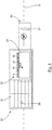
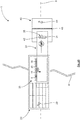
- the device 1 comprises a first measuring element 20, a second measuring element 30 and a retaining element 40. It is fixed at a point A and a point B of a surface on either side of a crack 8 and makes it possible to measure the variation in length between the point A and the point B in a measurement direction 5.
- the device 1 can be fixed on a wall, a ceiling or a floor or in a pluck formed by the intersection of two wall sections, the intersection of a ceiling and a section of wall or the intersection of a floor and a wall section.
- the first measuring element 20 is a support comprising graduations with millimeter precision in the measuring direction 5, a reading window 21 and a table 22. It also comprises at least one orifice 29 allowing the passage of a screw, for example, for its attachment to the point A. It may include in particular two orifices 29 allowing the passage of screws, the fixing at two distinct points of the support preventing any rotational movement of the support.
- the second measuring element 30 is a strip comprising a vernier with a precision of one tenth of a millimeter and a slot 31.
- the slot 31 is an oblong hole elongated in a direction orthogonal to the measurement direction 5.
- the oblong hole 31 may for example be obtained by drilling and then moving in a direction perpendicular to the measuring direction 5 of a bur in the thickness of the strip 30.
- the graduations of the support 20 opposite the vernier of the slider 30 form measuring means 25 which allow easy reading with a precision to the tenth of a millimeter, reliable and without risk of error of measuring the relative displacement in translation of the slider 30 with respect to the support 20.
- Table 22 on slide 30 allows to enter different data such as measurements made over time or general observations on the evolution of the crack 8.
- the support 20 and the strip 30 may be manufactured using any material sufficiently rigid and resistant to variations in humidity and / or temperature.
- the material must have a low coefficient of linear expansion.
- the material may be for example extruded PVC or polycarbonate.
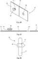
- the retaining element 40 may be manufactured in particular by a method of injection molding of plastic material.
- the plastic material used is a polypropylene, a polyamide or any other polymer commonly used for its plastic properties by those skilled in the art.
- the retaining retaining element 40 comprises a base 43 on which is disposed a stud 41, itself surmounted by a cleat 42. It also comprises at least one orifice 49 allowing the passage of a screw, for example, for its attachment to the point B. It may include in particular two orifices 49 allowing the passage of screws, the fixing at two distinct points of the retaining element preventing any rotational movement of the support. Said at least one orifice 49 may be provided by the injection mold or if it is not provided by the injection mold to be pierced in the injected part.
- the stud 41 is a straight cylinder whose base has a diameter substantially equal to but less than the width of the oblong hole 31 and whose height is greater than the thickness of the strip 30.
- a connecting element 35 is formed by the stud 41 sliding in the oblong hole 31 only in a direction orthogonal to the measuring direction 5.
- the connecting element 35 makes it possible to perform a reliable and error-free measurement of the variation of length between the point A and the point B in the measurement direction 5 even in the case where A and B are no longer aligned in the measuring direction 5.
- the connecting element 35 also ensures the integrity of the device 1.
- the cleat 42 is a rectangular parallelepiped having a width less than the diameter of the oblong hole 31 and a length strictly greater than the width of the oblong hole 31. It also has a doubly strange face. Its particular shape makes the connecting element 35 easily removable. Indeed, according to a first orientation of the retaining element 40, the cleat 42 can pass through the aperture 31. According to other orientations of the retaining element 40, in particular by rotating 90.degree. the axis of revolution of the stud 41, the cleat 42 on the contrary forms a stop.
- the retaining element 40 further comprises a groove 45 disposed on the base 43 between the stud 41 and the orifice 49.
- the groove 45 may be provided by the injection mold or if it is not provided by the mold injection be obtained by standard techniques of removal of material or punching on the injected part.
- the retainer 40 may then be bent at the groove as needed to allow attachment of the device 1 to points A and B.
Landscapes
- Physics & Mathematics (AREA)
- General Physics & Mathematics (AREA)
- Length-Measuring Instruments Using Mechanical Means (AREA)
- A Measuring Device Byusing Mechanical Method (AREA)
Applications Claiming Priority (1)
| Application Number | Priority Date | Filing Date | Title |
|---|---|---|---|
| FR1654940A FR3051895A1 (fr) | 2016-05-31 | 2016-05-31 | Dispositif de mesure unidirectionnelle de la variation de longueur entre deux points d'une surface |
Publications (2)
| Publication Number | Publication Date |
|---|---|
| EP3252425A1 true EP3252425A1 (de) | 2017-12-06 |
| EP3252425B1 EP3252425B1 (de) | 2018-12-12 |
Family
ID=56684058
Family Applications (1)
| Application Number | Title | Priority Date | Filing Date |
|---|---|---|---|
| EP17172575.7A Active EP3252425B1 (de) | 2016-05-31 | 2017-05-23 | Vorrichtung zum unidirektionalen messen der längenveränderung zwischen zwei punkten einer oberfläche |
Country Status (2)
| Country | Link |
|---|---|
| EP (1) | EP3252425B1 (de) |
| FR (1) | FR3051895A1 (de) |
Citations (6)
| Publication number | Priority date | Publication date | Assignee | Title |
|---|---|---|---|---|
| GB2110372A (en) * | 1981-11-13 | 1983-06-15 | Roger William Johnson | Monitoring cracks in buildings |
| DE4129032A1 (de) * | 1991-06-19 | 1992-12-24 | Reto Martinelli | Mauerwerksanker |
| DE9400755U1 (de) * | 1994-01-18 | 1994-03-10 | PPW-Polyplan Werkzeuge GmbH, 22457 Hamburg | Rißprüfer für Bauwerke |
| FR2784178A1 (fr) * | 1998-10-01 | 2000-04-07 | Janpierre Saugnac | Dispositif pour mesurer l'evolution de la distance entre un premier point et un second point d'une structure |
| FR2884911A1 (fr) * | 2005-04-25 | 2006-10-27 | Janpierre Saugnac | Dispositif de mesure de l'evolution d'une fissure fixee de facon amovible et profonde sur une paroi et ensemble a monter correspondant |
| WO2009028971A2 (en) * | 2007-08-31 | 2009-03-05 | Neostrain Sp. Z.O.O. | Device for measuring a divergence width of scratches, fractures and gaps in building objects |
-
2016
- 2016-05-31 FR FR1654940A patent/FR3051895A1/fr not_active Ceased
-
2017
- 2017-05-23 EP EP17172575.7A patent/EP3252425B1/de active Active
Patent Citations (6)
| Publication number | Priority date | Publication date | Assignee | Title |
|---|---|---|---|---|
| GB2110372A (en) * | 1981-11-13 | 1983-06-15 | Roger William Johnson | Monitoring cracks in buildings |
| DE4129032A1 (de) * | 1991-06-19 | 1992-12-24 | Reto Martinelli | Mauerwerksanker |
| DE9400755U1 (de) * | 1994-01-18 | 1994-03-10 | PPW-Polyplan Werkzeuge GmbH, 22457 Hamburg | Rißprüfer für Bauwerke |
| FR2784178A1 (fr) * | 1998-10-01 | 2000-04-07 | Janpierre Saugnac | Dispositif pour mesurer l'evolution de la distance entre un premier point et un second point d'une structure |
| FR2884911A1 (fr) * | 2005-04-25 | 2006-10-27 | Janpierre Saugnac | Dispositif de mesure de l'evolution d'une fissure fixee de facon amovible et profonde sur une paroi et ensemble a monter correspondant |
| WO2009028971A2 (en) * | 2007-08-31 | 2009-03-05 | Neostrain Sp. Z.O.O. | Device for measuring a divergence width of scratches, fractures and gaps in building objects |
Also Published As
| Publication number | Publication date |
|---|---|
| EP3252425B1 (de) | 2018-12-12 |
| FR3051895A1 (fr) | 2017-12-01 |
Similar Documents
| Publication | Publication Date | Title |
|---|---|---|
| FR2940437A1 (fr) | Outil, ensemble d'outillages et procede de reglage du pas des pales d'une helice de maquette | |
| US20140270623A1 (en) | Capillary action fiber sensor | |
| EP3252425B1 (de) | Vorrichtung zum unidirektionalen messen der längenveränderung zwischen zwei punkten einer oberfläche | |
| WO2017187090A1 (fr) | Dispositif de mesure de deformations endogenes | |
| EP3333317A1 (de) | Schienenführungssystem für eisenbahn | |
| EP3460437A1 (de) | Vorrichtung zur dynamischen kalibrierung eines drehmoments und/oder einer kraft | |
| FR3055914B1 (fr) | Dispositif d'entretoisement reglable en longueur | |
| BR112013012705B1 (pt) | Método e dispositivo para inspecionar a superfície de enroscamento de uma ligação tubular utilizada na indústria do petróleo | |
| EP1945881A1 (de) | Verfahren zur befestigung von blättern an einer stützstruktur und verbessertes befestigungselement | |
| EP2795141A1 (de) | System zum befestigen eines objekts an einem element mit befestigungsrille(n) und befestigungsvorrichtung für ein solches system | |
| FR3057628B1 (fr) | Dispositif indicateur de desserrage d'ecrou. | |
| EP4222446B1 (de) | System zur messung eines sich ändernden risses in einer wand oder dergleichen | |
| EP2072995B1 (de) | Messverfahren des Kriechens einer Dünnschicht, die zwischen zwei starre Substrate eingeschoben ist und deren eines Ende eingeklemmt wird | |
| US9593925B2 (en) | Measuring jig | |
| WO2025131752A1 (fr) | Dispositif de mesure de variations d'effort, de deformations mecaniques, de pressions hydrostatiques et de temperature, et procede de mesure associe | |
| EP3296465B1 (de) | Parkplatzschrankenvorrichtung | |
| FR2570487A1 (fr) | Appareil pour la mesure de diametres de pieces cylindriques | |
| EP1887316A1 (de) | Device for the measurement of deformations of a profile subject to one or more forces | |
| FR3041007A1 (fr) | Dispositif de maintien d'un element de parement a distance d'une membrane pare-vapeur et systeme constructif a double armature comprenant un tel dispositif | |
| EP3871562B1 (de) | Befestigungsvorrichtung für ein regal, und regal, das eine solche vorrichtung umfasst | |
| FR3108650A1 (fr) | Dispositif de fixation d’un dormant de menuiserie | |
| FR2665527A2 (fr) | Dispositif de mesure de la variation d'ouverture d'une fissure comportant un cadran de lecture a distance. | |
| EP1750099B1 (de) | Vorrichtung und Verfahren zur relativen Positionsmessung einer periodischen oder quasi-periodischen Markierung | |
| CN118641370B (zh) | 一种锚具静载试验台 | |
| WO2024213738A1 (fr) | Dispositif de fixation amovible d'un equipement et equipement correspondant |
Legal Events
| Date | Code | Title | Description |
|---|---|---|---|
| PUAI | Public reference made under article 153(3) epc to a published international application that has entered the european phase |
Free format text: ORIGINAL CODE: 0009012 |
|
| STAA | Information on the status of an ep patent application or granted ep patent |
Free format text: STATUS: THE APPLICATION HAS BEEN PUBLISHED |
|
| AK | Designated contracting states |
Kind code of ref document: A1 Designated state(s): AL AT BE BG CH CY CZ DE DK EE ES FI FR GB GR HR HU IE IS IT LI LT LU LV MC MK MT NL NO PL PT RO RS SE SI SK SM TR |
|
| AX | Request for extension of the european patent |
Extension state: BA ME |
|
| STAA | Information on the status of an ep patent application or granted ep patent |
Free format text: STATUS: REQUEST FOR EXAMINATION WAS MADE |
|
| 17P | Request for examination filed |
Effective date: 20180205 |
|
| RBV | Designated contracting states (corrected) |
Designated state(s): AL AT BE BG CH CY CZ DE DK EE ES FI FR GB GR HR HU IE IS IT LI LT LU LV MC MK MT NL NO PL PT RO RS SE SI SK SM TR |
|
| GRAP | Despatch of communication of intention to grant a patent |
Free format text: ORIGINAL CODE: EPIDOSNIGR1 |
|
| STAA | Information on the status of an ep patent application or granted ep patent |
Free format text: STATUS: GRANT OF PATENT IS INTENDED |
|
| RIC1 | Information provided on ipc code assigned before grant |
Ipc: G01B 5/30 20060101ALI20180601BHEP Ipc: E04G 23/00 20060101ALI20180601BHEP Ipc: G01B 5/14 20060101AFI20180601BHEP |
|
| INTG | Intention to grant announced |
Effective date: 20180625 |
|
| GRAS | Grant fee paid |
Free format text: ORIGINAL CODE: EPIDOSNIGR3 |
|
| GRAA | (expected) grant |
Free format text: ORIGINAL CODE: 0009210 |
|
| STAA | Information on the status of an ep patent application or granted ep patent |
Free format text: STATUS: THE PATENT HAS BEEN GRANTED |
|
| AK | Designated contracting states |
Kind code of ref document: B1 Designated state(s): AL AT BE BG CH CY CZ DE DK EE ES FI FR GB GR HR HU IE IS IT LI LT LU LV MC MK MT NL NO PL PT RO RS SE SI SK SM TR |
|
| REG | Reference to a national code |
Ref country code: GB Ref legal event code: FG4D Free format text: NOT ENGLISH |
|
| REG | Reference to a national code |
Ref country code: CH Ref legal event code: EP |
|
| REG | Reference to a national code |
Ref country code: AT Ref legal event code: REF Ref document number: 1076601 Country of ref document: AT Kind code of ref document: T Effective date: 20181215 |
|
| REG | Reference to a national code |
Ref country code: DE Ref legal event code: R096 Ref document number: 602017001335 Country of ref document: DE |
|
| REG | Reference to a national code |
Ref country code: IE Ref legal event code: FG4D Free format text: LANGUAGE OF EP DOCUMENT: FRENCH |
|
| REG | Reference to a national code |
Ref country code: NL Ref legal event code: MP Effective date: 20181212 |
|
| REG | Reference to a national code |
Ref country code: LT Ref legal event code: MG4D |
|
| PG25 | Lapsed in a contracting state [announced via postgrant information from national office to epo] |
Ref country code: FI Free format text: LAPSE BECAUSE OF FAILURE TO SUBMIT A TRANSLATION OF THE DESCRIPTION OR TO PAY THE FEE WITHIN THE PRESCRIBED TIME-LIMIT Effective date: 20181212 Ref country code: HR Free format text: LAPSE BECAUSE OF FAILURE TO SUBMIT A TRANSLATION OF THE DESCRIPTION OR TO PAY THE FEE WITHIN THE PRESCRIBED TIME-LIMIT Effective date: 20181212 Ref country code: NO Free format text: LAPSE BECAUSE OF FAILURE TO SUBMIT A TRANSLATION OF THE DESCRIPTION OR TO PAY THE FEE WITHIN THE PRESCRIBED TIME-LIMIT Effective date: 20190312 Ref country code: LV Free format text: LAPSE BECAUSE OF FAILURE TO SUBMIT A TRANSLATION OF THE DESCRIPTION OR TO PAY THE FEE WITHIN THE PRESCRIBED TIME-LIMIT Effective date: 20181212 Ref country code: ES Free format text: LAPSE BECAUSE OF FAILURE TO SUBMIT A TRANSLATION OF THE DESCRIPTION OR TO PAY THE FEE WITHIN THE PRESCRIBED TIME-LIMIT Effective date: 20181212 Ref country code: LT Free format text: LAPSE BECAUSE OF FAILURE TO SUBMIT A TRANSLATION OF THE DESCRIPTION OR TO PAY THE FEE WITHIN THE PRESCRIBED TIME-LIMIT Effective date: 20181212 Ref country code: BG Free format text: LAPSE BECAUSE OF FAILURE TO SUBMIT A TRANSLATION OF THE DESCRIPTION OR TO PAY THE FEE WITHIN THE PRESCRIBED TIME-LIMIT Effective date: 20190312 |
|
| REG | Reference to a national code |
Ref country code: AT Ref legal event code: MK05 Ref document number: 1076601 Country of ref document: AT Kind code of ref document: T Effective date: 20181212 |
|
| PG25 | Lapsed in a contracting state [announced via postgrant information from national office to epo] |
Ref country code: AL Free format text: LAPSE BECAUSE OF FAILURE TO SUBMIT A TRANSLATION OF THE DESCRIPTION OR TO PAY THE FEE WITHIN THE PRESCRIBED TIME-LIMIT Effective date: 20181212 Ref country code: SE Free format text: LAPSE BECAUSE OF FAILURE TO SUBMIT A TRANSLATION OF THE DESCRIPTION OR TO PAY THE FEE WITHIN THE PRESCRIBED TIME-LIMIT Effective date: 20181212 Ref country code: GR Free format text: LAPSE BECAUSE OF FAILURE TO SUBMIT A TRANSLATION OF THE DESCRIPTION OR TO PAY THE FEE WITHIN THE PRESCRIBED TIME-LIMIT Effective date: 20190313 Ref country code: RS Free format text: LAPSE BECAUSE OF FAILURE TO SUBMIT A TRANSLATION OF THE DESCRIPTION OR TO PAY THE FEE WITHIN THE PRESCRIBED TIME-LIMIT Effective date: 20181212 |
|
| PG25 | Lapsed in a contracting state [announced via postgrant information from national office to epo] |
Ref country code: NL Free format text: LAPSE BECAUSE OF FAILURE TO SUBMIT A TRANSLATION OF THE DESCRIPTION OR TO PAY THE FEE WITHIN THE PRESCRIBED TIME-LIMIT Effective date: 20181212 |
|
| PG25 | Lapsed in a contracting state [announced via postgrant information from national office to epo] |
Ref country code: CZ Free format text: LAPSE BECAUSE OF FAILURE TO SUBMIT A TRANSLATION OF THE DESCRIPTION OR TO PAY THE FEE WITHIN THE PRESCRIBED TIME-LIMIT Effective date: 20181212 Ref country code: PT Free format text: LAPSE BECAUSE OF FAILURE TO SUBMIT A TRANSLATION OF THE DESCRIPTION OR TO PAY THE FEE WITHIN THE PRESCRIBED TIME-LIMIT Effective date: 20190412 Ref country code: PL Free format text: LAPSE BECAUSE OF FAILURE TO SUBMIT A TRANSLATION OF THE DESCRIPTION OR TO PAY THE FEE WITHIN THE PRESCRIBED TIME-LIMIT Effective date: 20181212 Ref country code: IT Free format text: LAPSE BECAUSE OF FAILURE TO SUBMIT A TRANSLATION OF THE DESCRIPTION OR TO PAY THE FEE WITHIN THE PRESCRIBED TIME-LIMIT Effective date: 20181212 |
|
| PG25 | Lapsed in a contracting state [announced via postgrant information from national office to epo] |
Ref country code: EE Free format text: LAPSE BECAUSE OF FAILURE TO SUBMIT A TRANSLATION OF THE DESCRIPTION OR TO PAY THE FEE WITHIN THE PRESCRIBED TIME-LIMIT Effective date: 20181212 Ref country code: IS Free format text: LAPSE BECAUSE OF FAILURE TO SUBMIT A TRANSLATION OF THE DESCRIPTION OR TO PAY THE FEE WITHIN THE PRESCRIBED TIME-LIMIT Effective date: 20190412 Ref country code: SM Free format text: LAPSE BECAUSE OF FAILURE TO SUBMIT A TRANSLATION OF THE DESCRIPTION OR TO PAY THE FEE WITHIN THE PRESCRIBED TIME-LIMIT Effective date: 20181212 Ref country code: RO Free format text: LAPSE BECAUSE OF FAILURE TO SUBMIT A TRANSLATION OF THE DESCRIPTION OR TO PAY THE FEE WITHIN THE PRESCRIBED TIME-LIMIT Effective date: 20181212 Ref country code: SK Free format text: LAPSE BECAUSE OF FAILURE TO SUBMIT A TRANSLATION OF THE DESCRIPTION OR TO PAY THE FEE WITHIN THE PRESCRIBED TIME-LIMIT Effective date: 20181212 |
|
| REG | Reference to a national code |
Ref country code: DE Ref legal event code: R097 Ref document number: 602017001335 Country of ref document: DE |
|
| PLBE | No opposition filed within time limit |
Free format text: ORIGINAL CODE: 0009261 |
|
| STAA | Information on the status of an ep patent application or granted ep patent |
Free format text: STATUS: NO OPPOSITION FILED WITHIN TIME LIMIT |
|
| PG25 | Lapsed in a contracting state [announced via postgrant information from national office to epo] |
Ref country code: DK Free format text: LAPSE BECAUSE OF FAILURE TO SUBMIT A TRANSLATION OF THE DESCRIPTION OR TO PAY THE FEE WITHIN THE PRESCRIBED TIME-LIMIT Effective date: 20181212 Ref country code: AT Free format text: LAPSE BECAUSE OF FAILURE TO SUBMIT A TRANSLATION OF THE DESCRIPTION OR TO PAY THE FEE WITHIN THE PRESCRIBED TIME-LIMIT Effective date: 20181212 Ref country code: SI Free format text: LAPSE BECAUSE OF FAILURE TO SUBMIT A TRANSLATION OF THE DESCRIPTION OR TO PAY THE FEE WITHIN THE PRESCRIBED TIME-LIMIT Effective date: 20181212 |
|
| 26N | No opposition filed |
Effective date: 20190913 |
|
| PG25 | Lapsed in a contracting state [announced via postgrant information from national office to epo] |
Ref country code: MC Free format text: LAPSE BECAUSE OF FAILURE TO SUBMIT A TRANSLATION OF THE DESCRIPTION OR TO PAY THE FEE WITHIN THE PRESCRIBED TIME-LIMIT Effective date: 20181212 |
|
| REG | Reference to a national code |
Ref country code: BE Ref legal event code: MM Effective date: 20190531 |
|
| PG25 | Lapsed in a contracting state [announced via postgrant information from national office to epo] |
Ref country code: LU Free format text: LAPSE BECAUSE OF NON-PAYMENT OF DUE FEES Effective date: 20190523 |
|
| PG25 | Lapsed in a contracting state [announced via postgrant information from national office to epo] |
Ref country code: TR Free format text: LAPSE BECAUSE OF FAILURE TO SUBMIT A TRANSLATION OF THE DESCRIPTION OR TO PAY THE FEE WITHIN THE PRESCRIBED TIME-LIMIT Effective date: 20181212 |
|
| PG25 | Lapsed in a contracting state [announced via postgrant information from national office to epo] |
Ref country code: IE Free format text: LAPSE BECAUSE OF NON-PAYMENT OF DUE FEES Effective date: 20190523 |
|
| PG25 | Lapsed in a contracting state [announced via postgrant information from national office to epo] |
Ref country code: BE Free format text: LAPSE BECAUSE OF NON-PAYMENT OF DUE FEES Effective date: 20190531 |
|
| PG25 | Lapsed in a contracting state [announced via postgrant information from national office to epo] |
Ref country code: CH Free format text: LAPSE BECAUSE OF NON-PAYMENT OF DUE FEES Effective date: 20200531 Ref country code: LI Free format text: LAPSE BECAUSE OF NON-PAYMENT OF DUE FEES Effective date: 20200531 |
|
| PG25 | Lapsed in a contracting state [announced via postgrant information from national office to epo] |
Ref country code: CY Free format text: LAPSE BECAUSE OF FAILURE TO SUBMIT A TRANSLATION OF THE DESCRIPTION OR TO PAY THE FEE WITHIN THE PRESCRIBED TIME-LIMIT Effective date: 20181212 |
|
| PG25 | Lapsed in a contracting state [announced via postgrant information from national office to epo] |
Ref country code: MT Free format text: LAPSE BECAUSE OF FAILURE TO SUBMIT A TRANSLATION OF THE DESCRIPTION OR TO PAY THE FEE WITHIN THE PRESCRIBED TIME-LIMIT Effective date: 20181212 Ref country code: HU Free format text: LAPSE BECAUSE OF FAILURE TO SUBMIT A TRANSLATION OF THE DESCRIPTION OR TO PAY THE FEE WITHIN THE PRESCRIBED TIME-LIMIT; INVALID AB INITIO Effective date: 20170523 |
|
| GBPC | Gb: european patent ceased through non-payment of renewal fee |
Effective date: 20210523 |
|
| PG25 | Lapsed in a contracting state [announced via postgrant information from national office to epo] |
Ref country code: GB Free format text: LAPSE BECAUSE OF NON-PAYMENT OF DUE FEES Effective date: 20210523 |
|
| REG | Reference to a national code |
Ref country code: FR Ref legal event code: PLFP Year of fee payment: 6 |
|
| PG25 | Lapsed in a contracting state [announced via postgrant information from national office to epo] |
Ref country code: MK Free format text: LAPSE BECAUSE OF FAILURE TO SUBMIT A TRANSLATION OF THE DESCRIPTION OR TO PAY THE FEE WITHIN THE PRESCRIBED TIME-LIMIT Effective date: 20181212 |
|
| REG | Reference to a national code |
Ref country code: DE Ref legal event code: R081 Ref document number: 602017001335 Country of ref document: DE Owner name: SAUGNAC JAUGES, FR Free format text: FORMER OWNER: PRYL, GIEZ, FR |
|
| PGFP | Annual fee paid to national office [announced via postgrant information from national office to epo] |
Ref country code: DE Payment date: 20250527 Year of fee payment: 9 |
|
| PGFP | Annual fee paid to national office [announced via postgrant information from national office to epo] |
Ref country code: FR Payment date: 20250523 Year of fee payment: 9 |