EP3252300A1 - Valve mechanism and high-pressure fuel supply pump provided with same - Google Patents
Valve mechanism and high-pressure fuel supply pump provided with same Download PDFInfo
- Publication number
- EP3252300A1 EP3252300A1 EP16743050.3A EP16743050A EP3252300A1 EP 3252300 A1 EP3252300 A1 EP 3252300A1 EP 16743050 A EP16743050 A EP 16743050A EP 3252300 A1 EP3252300 A1 EP 3252300A1
- Authority
- EP
- European Patent Office
- Prior art keywords
- outer peripheral
- valve
- seat
- valve body
- peripheral surface
- Prior art date
- Legal status (The legal status is an assumption and is not a legal conclusion. Google has not performed a legal analysis and makes no representation as to the accuracy of the status listed.)
- Granted
Links
Images



Classifications
-
- F—MECHANICAL ENGINEERING; LIGHTING; HEATING; WEAPONS; BLASTING
- F02—COMBUSTION ENGINES; HOT-GAS OR COMBUSTION-PRODUCT ENGINE PLANTS
- F02M—SUPPLYING COMBUSTION ENGINES IN GENERAL WITH COMBUSTIBLE MIXTURES OR CONSTITUENTS THEREOF
- F02M59/00—Pumps specially adapted for fuel-injection and not provided for in groups F02M39/00 -F02M57/00, e.g. rotary cylinder-block type of pumps
- F02M59/20—Varying fuel delivery in quantity or timing
- F02M59/36—Varying fuel delivery in quantity or timing by variably-timed valves controlling fuel passages to pumping elements or overflow passages
-
- F—MECHANICAL ENGINEERING; LIGHTING; HEATING; WEAPONS; BLASTING
- F02—COMBUSTION ENGINES; HOT-GAS OR COMBUSTION-PRODUCT ENGINE PLANTS
- F02M—SUPPLYING COMBUSTION ENGINES IN GENERAL WITH COMBUSTIBLE MIXTURES OR CONSTITUENTS THEREOF
- F02M59/00—Pumps specially adapted for fuel-injection and not provided for in groups F02M39/00 -F02M57/00, e.g. rotary cylinder-block type of pumps
- F02M59/44—Details, components parts, or accessories not provided for in, or of interest apart from, the apparatus of groups F02M59/02 - F02M59/42; Pumps having transducers, e.g. to measure displacement of pump rack or piston
- F02M59/46—Valves
- F02M59/462—Delivery valves
-
- F—MECHANICAL ENGINEERING; LIGHTING; HEATING; WEAPONS; BLASTING
- F02—COMBUSTION ENGINES; HOT-GAS OR COMBUSTION-PRODUCT ENGINE PLANTS
- F02M—SUPPLYING COMBUSTION ENGINES IN GENERAL WITH COMBUSTIBLE MIXTURES OR CONSTITUENTS THEREOF
- F02M63/00—Other fuel-injection apparatus having pertinent characteristics not provided for in groups F02M39/00 - F02M57/00 or F02M67/00; Details, component parts, or accessories of fuel-injection apparatus, not provided for in, or of interest apart from, the apparatus of groups F02M39/00 - F02M61/00 or F02M67/00; Combination of fuel pump with other devices, e.g. lubricating oil pump
- F02M63/0012—Valves
- F02M63/0031—Valves characterized by the type of valves, e.g. special valve member details, valve seat details, valve housing details
- F02M63/0054—Check valves
-
- F—MECHANICAL ENGINEERING; LIGHTING; HEATING; WEAPONS; BLASTING
- F02—COMBUSTION ENGINES; HOT-GAS OR COMBUSTION-PRODUCT ENGINE PLANTS
- F02M—SUPPLYING COMBUSTION ENGINES IN GENERAL WITH COMBUSTIBLE MIXTURES OR CONSTITUENTS THEREOF
- F02M2200/00—Details of fuel-injection apparatus, not otherwise provided for
- F02M2200/04—Fuel-injection apparatus having means for avoiding effect of cavitation, e.g. erosion
Definitions
- the present invention relates to a high-pressure fuel supply pump that supplies fuel to an engine with high pressure and particularly relates to a discharge valve mechanism.
- a known high-pressure fuel pump described in JP 2011-80391 A is provided with a discharge mechanism including a discharge valve member, a valve seat member, a discharge valve spring, and a valve retaining member connected with the valve seat member so as to enclose a seat surface and the discharge valve spring to form a valve storage section inside the valve retaining member.
- the discharge valve mechanism including the valve retaining member formed to store the valve inside thereof, however, can merely ensure a limited fuel passage as illustrated in 8d of FIG. 13 of JP 2011-80391 A , leading to a problem of a limited flow of fuel due to the limited fuel flow-path.
- closing of the valve after completion of discharge causes a pressure difference across the valve leading to a backward flow of once-discharged fuel.
- the occurrence of the backward flow concentrates on the limited fuel passage, leading to a higher fuel flow rate at the time of the backward flow. This easily induces cavitation and decay energy of the generated cavitation might damage the seat surface, making it difficult to maintain the valve functions.
- the object of the present invention is to provide a high-quality valve mechanism capable of preventing the occurrence of damage in the valve function, and provide a high-pressure fuel supply pump including the same valve mechanism.
- the present invention provides a valve mechanism including a seat member having a seat section, a valve body to be attached to or detached from the seat section, and a housing member arranged on an outer peripheral side of the seat member.
- a first fluid flow-path is formed to connect an inner peripheral side and an outer peripheral side of the seat section in a case where the valve body is detached from the seat section
- a second fluid flow-path is formed to be connected with the first fluid flow-path, between an outer peripheral surface of the seat member and an inner peripheral surface of the housing member, or between an outer peripheral surface of the valve body and the inner peripheral surface of the housing member.
- the cross-sectional area along the axial direction of the valve mechanism of the second fluid flow-path is determined to be 0.18 mm square or above.
- the fuel flows backwards along a first fuel passage and a second fuel passage when the once-discharged fuel flows backwards due to the occurrence of the pressure difference across the valve, making it possible to reduce the flow rate of the fuel at the time of the backward flow.
- This can suppress the occurrence of cavitation and damage in the seat surface due to cavitation collapse, making it possible to enhance the quality of the valve functions.
- FIGS. 1 to 11 a configuration and operation of a high-pressure fuel supply pump according to a first embodiment of the present invention will be described with reference to FIGS. 1 to 11 .
- FIG. 1 is a general configuration of the high-pressure fuel supply system that uses the high-pressure fuel supply pump according to the first embodiment of the present invention.
- FIG. 1 a portion surrounded by a broken line indicates a pump housing 1 of the high-pressure fuel supply pump, with mechanisms and components indicated within this broken line being incorporated into the pump housing 1, so as to constitute the high-pressure fuel supply pump of the present embodiment. Moreover, dotted lines in the diagram indicate flows of electrical signals.
- the fuel in a fuel tank 20 is pumped up by a feed pump 21, then, fed to a fuel inlet 10a of the pump housing 1 via an intake pipe 28.
- the fuel that passes through the fuel inlet 10a reaches an intake port 30a of an electromagnetic intake valve mechanism 30 constituting a variable displacement mechanism, via a pressure pulsation reduction mechanism 9 and an intake passage 10c.
- the electromagnetic intake valve mechanism 30 includes an electromagnetic coil 30b. In a state where the electromagnetic coil 30b is energized, an electromagnetic plunger 30c compresses a spring 33 to come to a state of being moved to the left as illustrated in FIG. 1 , and this state is maintained. At this time, an intake valve body 31 attached on an end of the electromagnetic plunger 30c opens an inlet 32 that communicates with a pressurizing chamber 11 of the high-pressure fuel supply pump. When the electromagnetic coil 30b is not energized and there is no fluid differential pressure between the intake passage 10c (intake port 30a) and the pressurizing chamber 11, biasing force of the spring 33 biases the intake valve body 31 in a valve closing direction (right direction in FIG. 1 ), so as to put the inlet 32 into a closed state, and this state is maintained.
- FIG. 1 illustrates a state where the inlet 32 is closed.
- a plunger 2 is retained in the pressurizing chamber 11, slidably in the up-down direction in FIG. 1 .
- the volume of the pressurizing chamber 11 is increased and the fuel pressure therein is decreased.
- valve opening force due to fluid differential pressure of the fuel force to displace the intake valve body 31 leftward in FIG. 1
- the intake valve body 31 overcomes the biasing force of the spring 33 and opens the valve, then, opens the inlet 32.
- the plunger 2 is transitioned from the intake process to the compression process (rising process from a lower start point to an upper start point) while application of input voltage is maintained on the electromagnetic intake valve mechanism 30.
- the magnetic biasing force is maintained since an energization state of the electromagnetic coil 30b is maintained, and thus, the intake valve body 31 continuously maintains the open state of the valve.
- the volume of the pressurizing chamber 11 decreases together with a compression movement of the plunger 2
- the fuel once taken into the pressurizing chamber 11 passes again through a portion between the intake valve body 31 in the valve-open state and the inlet 32, and returns to the intake passage 10c (intake port 30a). Accordingly, there is no increase in the pressure of the pressurizing chamber 11. This process is referred to as a return process.
- the magnetic biasing force working on the electromagnetic plunger 30c is eliminated after a predetermined time (magnetic and mechanical delay time). Consequently, the biasing force of the spring 33 constantly working on the intake valve body 31, and fluid force generated by pressure loss of the inlet 32 causes the intake valve body 31 to move rightward in FIG. 1 , so as to close the inlet 32. From the point on which the inlet 32 is closed, the fuel pressure within the pressurizing chamber 11 increases with the rise of the plunger 2.
- the fuel remaining in the pressurizing chamber 11 is discharged under high pressure via a discharge valve unit (discharge valve mechanism) 8, and supplied to the common rail 23.
- a discharge valve unit discharge valve mechanism 8
- This process is referred to as a discharge process.
- the compression process of the plunger 2 includes the return process and the discharge process.
- the ECU 27 controls the timing of de-energization of the electromagnetic coil 30c of the electromagnetic intake valve mechanism 30, thereby enabling the control of the amount of discharged high-pressure fuel.
- the timing of de-energization of the electromagnetic coil 30b is advanced, the ratio of the return process among the compression process is decreased while the ratio of the discharge process among the compression process is increased. That is, the fuel returned to the intake passage 10c (intake port 30a) is decreased, and the discharged fuel with high-pressure is increased.
- the above-described timing of de-energization is delayed, the ratio of the return process among the compression process is increased while the ratio of the discharge process among the compression process is decreased. That is, the fuel returned to the intake passage 10c is increased, and the discharged fuel with high-pressure is decreased.
- the above-described de-energization timing is controlled by an instruction from the ECU 27.
- the ECU 27 controls the timing of de-energization of the electromagnetic coil, thereby enabling discharging the fuel with high pressure in the amount needed by the internal combustion engine.
- the discharge valve unit (discharge valve mechanism) 8 is provided between an exit side of the pressurizing chamber 11 and the outlet (discharge-side piping connection portion) 13.
- the discharge valve unit (discharge valve mechanism) 8 includes a valve seat member 8a, a discharge valve member 8b, a discharge valve spring 8c, and a valve retaining member 8d. In a state where there is no fuel differential pressure between the pressurizing chamber 11 and the outlet 13, the discharge valve member 8b is press-bonded to the valve seat member 8a due to the biasing force by the discharge valve spring 8c and in a valve-closed state.
- discharge valve member 8b opens against the discharge valve spring 8c, then, the fuel within the pressurizing chamber 11 is discharged to the outlet 13 via the discharge valve unit (discharge valve mechanism) 8.
- the discharge valve member 8b opens the valve, and thereafter, comes in contact with a stopper 805 formed on the valve retaining member 8d, whereby, the operation of the discharge valve member 8b is limited. Therefore, the stroke of the discharge valve member 8b is appropriately determined by the valve retaining member 8d.
- the discharge valve unit (discharge valve mechanism) 8 operates as a check valve for limiting the flow direction of the fuel. Note that details of the configuration of the discharge valve unit (discharge valve mechanism) 8 will be described below with reference to FIGS. 2 to 5 , FIG.7 , and FIG. 11 .
- the fuel directed to the fuel inlet 10a is pressurized to a high pressure by a needed amount within the pressurizing chamber 11 of the pump housing 1 by reciprocation of the plunger 2, and then, pumped from the outlet 13 to the common rail 23 as a high-pressure pipe, via the discharge valve unit (discharge valve mechanism) 8.
- An injector 24 and a pressure sensor 26 are attached on the common rail 23.
- the injector 24 is attached in accordance with the number of cylinders.
- the injector 24 performs open/close operation and injects a predetermined amount of fuel into the cylinder in accordance with the control signal from the ECU 27.
- discharge valve unit 8 discharge valve mechanism 8 used in the high-pressure fuel supply pump according to the present embodiment will be described with reference to FIGS. 2 and 3 .
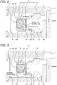
- FIG. 2 is an enlarged view of the discharge valve mechanism portion (compression process state).
- FIG. 3 is an enlarged view of the discharge valve mechanism portion (intake process state).
- the discharge valve unit (discharge valve mechanism) 8 is provided at an exit of the pressurizing chamber 11.
- the discharge valve unit (discharge valve mechanism) 8 includes the valve seat member 8a, the discharge valve member 8b, the discharge valve spring 8c, and the valve retaining member 8d as a discharge valve stopper.
- the discharge valve unit (discharge valve mechanism) 8 is assembled outside the pump housing 1 by performing laser welding onto a weld portion 8e, and thereafter, the assembled discharge valve unit (discharge valve mechanism) 8 is press-fit into the pump housing 1 and fixed at a press-fit portion 8a1.
- attachment jig is applied to a load receiving portion 8a2 formed as a stepped surface larger than the weld portion 8e in diameter, and force is applied to the right side in the figure, so as to perform press-fitting and fixing onto the pump housing 1.
- a passage 8d2 is provided at a discharge-side end of the valve retaining member 8d. Therefore, in a state where there is no fuel differential pressure between the pressurizing chamber 11 and the outlet 12 on the discharge valve unit (discharge valve mechanism) 8, the discharge valve member 8b is pressed against a seat surface portion 8a3 of the valve seat member 8a by the biasing force of the discharge valve spring 8c, in a seated state (valve-closed state).
- the discharge valve member 8b opens against the discharge valve spring 8c, as illustrated in FIG.
- the fuel within the pressurizing chamber 11 is discharged to the common rail 23 via the outlet 12.
- the fuel passes through a single or a plurality of passages 8d1 provided on the valve retaining member 8d and is pumped from the pressurizing chamber 11 to the outlet 12.
- the discharge valve member 8b returns to the initial closed state. With this configuration, it is possible to close the discharge valve member 8b after discharging the high-pressure fuel.
- valve opening pressure of the discharge valve member 8b is set to 0.1 MPa or below.
- the feed pressure is 0.4 MPa, and the discharge valve member 8b is opened by the feed pressure.
- the discharge valve member 8b When the discharge valve member 8b opens the valve, the discharge valve member 8b comes in contact with a stopper 805 provided on an inner peripheral portion of the valve retaining member 8d, whereby the operation of the discharge valve member 8b is limited. Accordingly, the stroke of the discharge valve member 8b is appropriately determined with a step formed by the stopper 805 provided at the inner peripheral portion of the valve retaining member 8d. Moreover, when the discharge valve member 8b repeats valve opening motion and valve closing motion, the inner peripheral surface 806 of the valve retaining member 8d guides the motion such that the discharge valve member 8b moves solely in the stroke direction.
- the discharge valve unit (discharge valve mechanism) 8 operates as a check valve for limiting the flow direction of the fuel.
- a fluid flow-path on which the fuel passes toward an inner peripheral side and an outer peripheral side of the valve seat member 8a, and further passes through the passage 8d1 provided on the valve retaining member 8d among the passage of the fuel pumped from the pressurizing chamber 11 to the outlet 12, is defined as a first fluid flow-path 8f1, and a fluid flow-path for the fuel that flows from the inner peripheral side to the outer peripheral surface of the valve seat member 8a, and that is connected with the first fluid flow-path 8f1 at a portion formed with the inner peripheral wall of the valve retaining member 8d, or between the outer peripheral surface of the discharge valve member 8b and the inner peripheral wall of the valve retaining member 8d, is defined as a second fluid flow-path 8f2.
- the fuel is compressed within the pressurizing chamber 11 together with the rise of the plunger 2, and when the fuel pressure within the pressurizing chamber 11 exceeds the fuel pressure of the outlet 12, that is, when the fuel pressure increases to the valve opening pressure by the discharge valve spring 8c, or above, the discharge valve member 8b opens against the discharge valve spring 8c as illustrated in FIG. 2 . Subsequently, the fuel within the pressurizing chamber 11 passes through the first fluid flow-path 8f1, the second fluid flow-path 8f2, and the outlet 12, and then, is discharged to the common rail 23.
- the discharge valve member 8b returns to the initial closed state. While this enables closing of the discharge valve member 8b after discharging high-pressure fuel, the fuel pressure within the pressurizing chamber 11 is decreased due to the movement of the plunger 2 that has transitioned from the compression process to the intake process during the valve closing operation. This leads to the state where the fuel pressure at the outlet 12 > the fuel pressure of the pressurizing chamber 11. This causes the high-pressure fuel to flow backwards to the low-pressure pressurizing chamber 11 in a process of closing of the discharge valve member 8b after discharging high-pressure fuel ( FIG. 3 ).
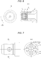
- FIG. 7 illustrating a known discharge valve portion mechanism is a cross-sectional view taken along the seat surface 8a3 that is orthogonal to a stroke axis of the discharge valve member 8b of the discharge valve unit (discharge valve mechanism) 8 and formed when the valve seat member 8a and the discharge valve member 8b face with each other when the valve is closed.
- the fuel that flows backwards from the outlet 12 to the pressurizing chamber 11 can only be flown backwards through the fluid flow-path 8f1 that passes through the passage 8d1 provided on the valve retaining member 8d. This causes the fuel that flows backwards to be concentrated at the fluid flow-path 8f1, leading to a higher flow rate. Consequently, the backwards flowing fuel reaches a pressure that is the above-described saturated vapor pressure or below and this generates cavitation. When cavitation collapse occurs, the valve seat member 8a and the discharge valve member 8b would be damaged.
- FIG. 8 illustrating a discharge valve portion mechanism according to the present embodiment is a cross-sectional view taken along the seat surface 8a3 that is orthogonal to a stroke axis of the discharge valve member 8b of the discharge valve unit (discharge valve mechanism) 8 and formed when the valve seat member 8a and the discharge valve member 8b face with each other when the valve is closed.
- the fuel that flows backwards from the outlet 12 toward the pressurizing chamber 11 can flow backwards from a full circumference of 360° including the fluid flow-path 8f1 that passes through the passage 8d1 provided on the valve retaining member 8d and the second fluid passage 8f2.
- the fuel that flows backwards can flow evenly without causing the backward flow to be concentrated on the backward fluid flow-path 8f1 on the known discharge valve mechanism illustrated in FIG. 7 , making it possible to suppress an increase in the flow rate.
- the valve mechanism includes the seat member 8a having the seat section (seat surface 8a3), the valve body (discharge valve member 8b) that is attached to or detached from the seat surface 8a3, and the housing member (valve retaining member 8d) arranged on the outer peripheral side of the seat member 8a.
- the first fluid flow-path (fluid flow-path 8f1) connecting the inner peripheral side and the outer peripheral side of the seat section (seat surface 8a3) is formed in a case where the valve body (discharge valve member 8b) is detached from the seat section (seat surface 8a3), and the second fluid flow-path 8f2 connected with the first fluid flow-path (fluid flow-path 8f1) is formed between the outer peripheral surface of the seat member 8a and the inner peripheral surface of the housing member (valve retaining member 8d) or between the outer peripheral surface of the valve body (discharge valve member 8b) and the inner peripheral surface of the housing member (valve retaining member 8d).
- the present exemplary embodiment is characterized by having a cross-sectional area of the second fluid flow-path 8f2 along the axial direction of the valve mechanism is 0.18 square mm or above.
- the horizontal axis of FIG. 9 indicates a cross-sectional area 8g of the second fluid flow-path 8f2 along the axial direction of the valve mechanism, as a variable, and the vertical axis of FIG. 9 indicates a cavitation occurrence index.
- the cavitation index represents an index obtained by fluid analysis. The greater the cavitation index, the more likely the cavitation occurs.
- the cross-sectional area 8g of the second fluid flow-path 8f2 along the axial direction of the valve mechanism indicates that it is possible to suppress the occurrence of cavitation by setting the size preferably to 0.18 square mm or above.
- a flow-path area 8i at a time of the maximum stroke of the discharge valve member 8b at an entrance of the housing member (valve retaining member 8d) of the first fluid flow-path 8f1 is 0.29 square mm.
- the flow-path area 8i is defined as the area of a cross-section obtained by projecting the cross-section of the fluid flow-path 8f1 to the passage 8d1 of the valve retaining member 8d, when the fluid flow-path 8f1 is viewed from the side surface (lower side of FIG. 5 ) in a state where the stroke of the discharge valve member 8b is at the maximum in FIG. 5 .
- the both sides of the cross-section of the fluid flow-path 8f1, facing with each other, are constituted with a portion of the passage 8d1 of the valve retaining member 8d.
- another set of both sides is constituted with the seat surface 8a3 and its opposing attachment surface of the discharge valve member 8b.
- the above-described cross-sectional area 8g of the second fluid flow-path 8f2 is 2/3 times or more of the above-described flow-path area 8i of the first fluid flow-path 8f1.
- the passage 8d1 of the valve retaining member 8d is provided in plural and in a form of circle, and the cross-sectional area (fluid flow-path area) of the passage 8d1 in the flow direction is 1.89 square mm.
- the passage 8d1 of the valve retaining member 8d is the passage as illustrated in FIG. 3 , in which a tapered surface is not considered.
- the above-described cross-sectional area 8g of the second fluid flow-path 8f2 is formed to be 1/10 times or more of the fluid flow-path area of the passage 8d1 of the valve retaining member 8d. This makes it possible to suppress the occurrence of the above-described cavitation.
- the cross-sectional area 8g of the second fluid flow-path 8f2 includes the outer peripheral surface of the seat member 8a, the outer peripheral surface of the discharge valve member 8b, and the inner peripheral surface of the valve retaining member 8d.
- the cross-sectional area 8g of the second fluid flow-path 8f2 is formed with a seat member-side cross-sectional area and a discharge valve member-side cross-sectional area.
- the seat member-side cross-sectional area includes the outer peripheral surface of the valve seat member 8a, the inner peripheral surface of the valve retaining member 8d, and an extension line extending in an outer peripheral direction, that is perpendicular to the axial direction, from the seat section, and is formed along the axial direction.
- the discharge valve member-side cross-sectional area is constituted with the outer peripheral surface of the discharge valve member 8b, the inner peripheral surface of the valve retaining member 8d, and the above-described extension line, and is formed along the axial direction.
- the seat member-side cross sectional area is supposed to be greater than the discharge valve member-side cross sectional area.
- the size of the seat member-side cross sectional area in the axial direction is preferably greater than the size of the discharge valve member-side cross sectional area in the axial direction.
- the second fluid flow-path 8f2 is preferably formed on the outer peripheral side of the valve seat member 8a, or preferably formed at a full circumference of the outer peripheral side of the discharge valve body 8b.
- a cylinder is provided within the pressurizing chamber 11, and the second fluid flow-path 8f2 is arranged so as to span an upper end portion of the cylinder in a piston motion direction within the pressurizing chamber 11.
- a stepped portion 8a4 is formed on the outer peripheral side of the valve seat member 8a.
- the stepped portion 8a4 is a recess that is recessed toward the inside, on the inner peripheral side opposite to the side of the discharge valve body 8b.
- a gap is formed between the recess and the housing member, thereby forming the second fluid flow-path 8f2.
- This stepped portion 8a4 allows the valve body retaining member to be inserted without riding on the seat member, making possible to enhance the valve unit assembly efficiency.
- FIG. 11 A second exemplary embodiment of the present invention will be described with reference to FIG. 11 .
- valve body housing 8d might bump a right-angled stepped portion of the seat member 8A when the valve body housing 8d is attached to the seat member 8A.
- a seat member slope 8h is formed on the outer peripheral surface of the valve seat member 8a.
- the seat member slope 8h is formed to expand toward the outer peripheral side, in a direction from the discharge valve member 8b toward the seat member 8a.
- a gap is formed between the seat member slope 8h and the housing member (valve retaining member 8d).
- the fuel that flows backwards from the exit 12 toward the pressurizing chamber 11 can flow backwards from a full circumference of 360° including a flow-path 8f4 that passes through the passage 8d1 provided on the valve retaining member 8d and the second fluid flow-path 8f3. Accordingly, the fuel that flows backwards can flow evenly without causing the backward flow to be concentrated on the backward fluid flow-path 8f1 on the known discharge valve mechanism illustrated in FIG. 7 , making it possible to suppress an increase in the flow rate. This leads to suppression of the occurrence of cavitation and suppression of damage on the seat surface due to cavitation collapse, making it possible to maintain the function of a check valve of limiting the flow direction of the fuel in the discharge valve unit (discharge valve mechanism) 8.
- a flat portion is formed on a portion closer to the discharge valve member 8b than the seat member slope.
- the flat portion is substantially parallel to the inner peripheral surface of the valve body retaining member 8d. This makes it possible to ensure the size of the second fluid flow-path 8f3 formed between the flat portion and the valve body retaining member 8d. Accordingly, the fuel that flows backwards from the exit 12 to the pressurizing chamber 11 can flow backwards from a full circumference of 360° including the fluid flow-path 8f4 that passes through the passage 8d1 provided on the valve retaining member 8d and the second fluid passage 8f3.
- the fuel that flows backwards can flow evenly without causing the backward flow to be concentrated on the backward fluid flow-path 8f1 on the known discharge valve mechanism illustrated in FIG. 7 , making it possible to suppress an increase in the flow rate.
- This can suppress the occurrence of cavitation and ultimately suppress the damage of the seat surface due to cavitation collapse.
- the discharge valve body 8b illustrated in FIG. 11 is configured to have a valve body slope to be expanding from the valve seat member 8a toward the outer peripheral side along the direction toward the discharge valve body 8b on the outer peripheral side of the contact surface with the valve seat member 8a.
- This configuration forms a gap between the valve body slope and the valve body retaining member 8d.
- the slope angle formed between the seat surface and the both ends of the valve seat member slope is made to be greater than the inclination angle formed between the seat surface and the end portion of the discharge valve body slope.
- the fuel that flows backwards from the exit 12 to the pressurizing chamber 11 can flow backwards from a full circumference of 360° including the fluid flow-path 8f1 that passes through the passage 8d1 provided on the valve retaining member 8d and the second fluid passage 8f3.
- the fuel that flows backwards can flow evenly without causing the backward flow to be concentrated on the backward fluid flow-path 8f1 on the known discharge valve mechanism illustrated in FIG. 7 , making it possible to suppress an increase in the flow rate.
- This makes it possible to suppress the generation of cavitation, leading to ultimate suppression of the damage in the seat surface 8a3 due to cavitation collapse, or makes it possible to maintain the function as a check valve of limiting the flow direction of the fuel of the discharge valve unit (discharge valve mechanism) 8.
- the inclination angle is formed to be smaller than the valve seat member slope, and thus, it is possible to ensure the sliding length of the outer peripheral surface of the discharge valve member 8b and the valve body retaining member 8d, and to suppress inclination of the discharge valve member 8b, leading to achievement of smooth opening/closing of the valve.
- a flat portion 8k is formed on a portion opposite to the discharge valve body 8b, more than the valve seat member slope 8h.
- the flat portion 8k is substantially parallel to the inner peripheral surface of the valve body retaining member 8d.
- the outer peripheral surface of the valve seat member 8a is recessed toward the inner peripheral side, on the opposite side of the valve body across the flat portion to form a stepped portion 8a4, and a gap is formed between the stepped portion 8a4 and the valve body retaining member 8d. Accordingly, when the valve body retaining member 8d is assembled to the valve seat member 8a, it is possible to suppress riding of the valve body retaining member 8d onto the valve seat member 8a ( FIG. 11 ).
- valve seat member slope is formed to be inclined to the outer peripheral side from the end portion of the flat portion of the valve seat section, it is possible to achieve an effect similar to the effects of the present exemplary embodiment.
- the seat member slope is preferably formed in a tapered shape. While the exemplary embodiments of the present invention have been described as above, by combining the configurations described in Exemplary Embodiments 1 and 2, it is possible to synergistically obtain the effects that would be obtained by individual exemplary embodiments.
Landscapes
- Engineering & Computer Science (AREA)
- Chemical & Material Sciences (AREA)
- Combustion & Propulsion (AREA)
- Mechanical Engineering (AREA)
- General Engineering & Computer Science (AREA)
- Fuel-Injection Apparatus (AREA)
- Check Valves (AREA)
- Details Of Valves (AREA)
Abstract
Description
- The present invention relates to a high-pressure fuel supply pump that supplies fuel to an engine with high pressure and particularly relates to a discharge valve mechanism.
- A known high-pressure fuel pump described in
JP 2011-80391 A -
- PTL 1:
JP 2011-80391 A - PTL 2:
JP 5180365 B2 - With the configuration of the discharge valve mechanism including the valve retaining member formed to store the valve inside thereof, however, can merely ensure a limited fuel passage as illustrated in 8d of FIG. 13 of
JP 2011-80391 A - The object of the present invention is to provide a high-quality valve mechanism capable of preventing the occurrence of damage in the valve function, and provide a high-pressure fuel supply pump including the same valve mechanism.
- In order to achieve the above-described object, the present invention provides a valve mechanism including a seat member having a seat section, a valve body to be attached to or detached from the seat section, and a housing member arranged on an outer peripheral side of the seat member. In this, a first fluid flow-path is formed to connect an inner peripheral side and an outer peripheral side of the seat section in a case where the valve body is detached from the seat section, a second fluid flow-path is formed to be connected with the first fluid flow-path, between an outer peripheral surface of the seat member and an inner peripheral surface of the housing member, or between an outer peripheral surface of the valve body and the inner peripheral surface of the housing member. The cross-sectional area along the axial direction of the valve mechanism of the second fluid flow-path is determined to be 0.18 mm square or above.
- According to the present invention configured as above, the fuel flows backwards along a first fuel passage and a second fuel passage when the once-discharged fuel flows backwards due to the occurrence of the pressure difference across the valve, making it possible to reduce the flow rate of the fuel at the time of the backward flow. This can suppress the occurrence of cavitation and damage in the seat surface due to cavitation collapse, making it possible to enhance the quality of the valve functions.
-
- [
FIG. 1] FIG. 1 is an exemplary fuel supply system using a high-pressure fuel supply pump according to a first exemplary embodiment of the present invention. - [
FIG. 2] FIG. 2 is a longitudinal cross-sectional view of a discharge process of a discharge valve mechanism according to the first exemplary embodiment of the present invention. - [
FIG. 3] FIG. 3 is a longitudinal cross-sectional view of an intake process of a discharge valve mechanism according to the first exemplary embodiment of the present invention. - [
FIG. 4] FIG. 4 is a cross-sectional view of the discharge valve mechanism when the valve is open, according to the first exemplary embodiment of the present invention. - [
FIG. 5] FIG. 5 is an enlarged view of the discharge valve mechanism when the valve is open, illustrating a fluid flow-path, according to the first exemplary embodiment of the present invention. - [
FIG. 6] FIG. 6 is a cross-sectional view of a discharge valve mechanism when the valve is closed, for explaining an object of the present invention. - [
FIG. 7] FIG. 7 is a transverse cross-sectional view of discharge valve mechanism, illustrating the flow of fuel at backward flow, for explaining the object of the present invention. - [
FIG. 8] FIG. 8 is a transverse cross-sectional view of discharge valve mechanism, illustrating the flow of fuel at backward flow, according to the first exemplary embodiment of the present invention. - [
FIG. 9] FIG. 9 is a graph illustrating a relationship between the cross-sectional area of a fuel passage and damage in the seat section due to cavitation. - [
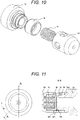
FIG. 10] FIG. 10 is an exploded perspective view of the discharge valve mechanism according to the first exemplary embodiment of the present invention. - [
FIG. 11] FIG. 11 is a longitudinal cross-sectional view of a discharge valve mechanism according to a second exemplary embodiment of the present invention. - Hereinafter, exemplary embodiments of the present invention will be described with reference to the drawings.
- Hereinafter, a configuration and operation of a high-pressure fuel supply pump according to a first embodiment of the present invention will be described with reference to
FIGS. 1 to 11 . - First, a configuration of a high-pressure fuel supply system that uses the high-pressure fuel supply pump according to the present embodiment will be described with reference to
FIG. 1 . -
FIG. 1 is a general configuration of the high-pressure fuel supply system that uses the high-pressure fuel supply pump according to the first embodiment of the present invention. - In
FIG. 1 , a portion surrounded by a broken line indicates apump housing 1 of the high-pressure fuel supply pump, with mechanisms and components indicated within this broken line being incorporated into thepump housing 1, so as to constitute the high-pressure fuel supply pump of the present embodiment. Moreover, dotted lines in the diagram indicate flows of electrical signals. - The fuel in a
fuel tank 20 is pumped up by afeed pump 21, then, fed to afuel inlet 10a of thepump housing 1 via anintake pipe 28. The fuel that passes through thefuel inlet 10a reaches anintake port 30a of an electromagneticintake valve mechanism 30 constituting a variable displacement mechanism, via a pressurepulsation reduction mechanism 9 and anintake passage 10c. - The electromagnetic
intake valve mechanism 30 includes anelectromagnetic coil 30b. In a state where theelectromagnetic coil 30b is energized, anelectromagnetic plunger 30c compresses aspring 33 to come to a state of being moved to the left as illustrated inFIG. 1 , and this state is maintained. At this time, anintake valve body 31 attached on an end of theelectromagnetic plunger 30c opens aninlet 32 that communicates with a pressurizingchamber 11 of the high-pressure fuel supply pump. When theelectromagnetic coil 30b is not energized and there is no fluid differential pressure between theintake passage 10c (intake port 30a) and the pressurizingchamber 11, biasing force of thespring 33 biases theintake valve body 31 in a valve closing direction (right direction inFIG. 1 ), so as to put theinlet 32 into a closed state, and this state is maintained.FIG. 1 illustrates a state where theinlet 32 is closed. - A
plunger 2 is retained in the pressurizingchamber 11, slidably in the up-down direction inFIG. 1 . When theplunger 2 is displaced downward inFIG. 1 being in a state of an intake process due to rotation of a cam in an internal combustion engine, the volume of the pressurizingchamber 11 is increased and the fuel pressure therein is decreased. In this process, when the fuel pressure within the pressurizingchamber 11 is decreased below the pressure of theintake passage 10c (intake port 30a), valve opening force due to fluid differential pressure of the fuel (force to displace theintake valve body 31 leftward inFIG. 1 ) is generated on theintake valve body 31. Due to this valve opening force, theintake valve body 31 overcomes the biasing force of thespring 33 and opens the valve, then, opens theinlet 32. In this state, when a control signal from anECU 27 is applied to the electromagneticintake valve mechanism 30, an electric current flows through theelectromagnetic coil 30b of theelectromagnetic intake valve 30, and then, magnetic biasing force moves theelectromagnetic plunger 30c leftward inFIG. 1 , so as to maintain theinlet 32 in an open state. - The
plunger 2 is transitioned from the intake process to the compression process (rising process from a lower start point to an upper start point) while application of input voltage is maintained on the electromagneticintake valve mechanism 30. At this time, the magnetic biasing force is maintained since an energization state of theelectromagnetic coil 30b is maintained, and thus, theintake valve body 31 continuously maintains the open state of the valve. While the volume of the pressurizingchamber 11 decreases together with a compression movement of theplunger 2, the fuel once taken into the pressurizingchamber 11 passes again through a portion between theintake valve body 31 in the valve-open state and theinlet 32, and returns to theintake passage 10c (intake port 30a). Accordingly, there is no increase in the pressure of the pressurizingchamber 11. This process is referred to as a return process. - When energization of the
electromagnetic coil 30b is stopped in the return process, the magnetic biasing force working on theelectromagnetic plunger 30c is eliminated after a predetermined time (magnetic and mechanical delay time). Consequently, the biasing force of thespring 33 constantly working on theintake valve body 31, and fluid force generated by pressure loss of theinlet 32 causes theintake valve body 31 to move rightward inFIG. 1 , so as to close theinlet 32. From the point on which theinlet 32 is closed, the fuel pressure within the pressurizingchamber 11 increases with the rise of theplunger 2. Subsequently, when the fuel pressure within the pressurizingchamber 11 exceeds a pressure that is greater than the fuel pressure at theoutlet 13 by a predetermined value, the fuel remaining in the pressurizingchamber 11 is discharged under high pressure via a discharge valve unit (discharge valve mechanism) 8, and supplied to thecommon rail 23. This process is referred to as a discharge process. As described above, the compression process of theplunger 2 includes the return process and the discharge process. - While pressure pulsation occurs on the intake passage due to the fuel returned to the
intake passage 10c during the return process, the pressure pulsation occurs as a slight backward flow from theinlet 10a to theintake pipe 28. Most portion of the returned fuel is absorbed by the pressurepulsation reduction mechanism 9. - The
ECU 27 controls the timing of de-energization of theelectromagnetic coil 30c of the electromagneticintake valve mechanism 30, thereby enabling the control of the amount of discharged high-pressure fuel. When the timing of de-energization of theelectromagnetic coil 30b is advanced, the ratio of the return process among the compression process is decreased while the ratio of the discharge process among the compression process is increased. That is, the fuel returned to theintake passage 10c (intake port 30a) is decreased, and the discharged fuel with high-pressure is increased. In contrast, when the above-described timing of de-energization is delayed, the ratio of the return process among the compression process is increased while the ratio of the discharge process among the compression process is decreased. That is, the fuel returned to theintake passage 10c is increased, and the discharged fuel with high-pressure is decreased. The above-described de-energization timing is controlled by an instruction from theECU 27. - As described above, the
ECU 27 controls the timing of de-energization of the electromagnetic coil, thereby enabling discharging the fuel with high pressure in the amount needed by the internal combustion engine. - Within the
pump housing 1, the discharge valve unit (discharge valve mechanism) 8 is provided between an exit side of the pressurizingchamber 11 and the outlet (discharge-side piping connection portion) 13. The discharge valve unit (discharge valve mechanism) 8 includes avalve seat member 8a, adischarge valve member 8b, adischarge valve spring 8c, and avalve retaining member 8d. In a state where there is no fuel differential pressure between the pressurizingchamber 11 and theoutlet 13, thedischarge valve member 8b is press-bonded to thevalve seat member 8a due to the biasing force by thedischarge valve spring 8c and in a valve-closed state. When the fuel pressure within the pressurizingchamber 11 exceeds the pressure that is greater than the fuel pressure at theoutlet 13 by a predetermined value, thedischarge valve member 8b opens against thedischarge valve spring 8c, then, the fuel within the pressurizingchamber 11 is discharged to theoutlet 13 via the discharge valve unit (discharge valve mechanism) 8. - The
discharge valve member 8b opens the valve, and thereafter, comes in contact with astopper 805 formed on thevalve retaining member 8d, whereby, the operation of thedischarge valve member 8b is limited. Therefore, the stroke of thedischarge valve member 8b is appropriately determined by thevalve retaining member 8d. - Moreover, when the
discharge valve member 8b repeats valve opening motion and valve closing motion, aninner wall 806 of thevalve retaining member 8d guides the motion to enable the motion to be done smoothly in the stroke direction. By the above-described configuration, the discharge valve unit (discharge valve mechanism) 8 operates as a check valve for limiting the flow direction of the fuel. Note that details of the configuration of the discharge valve unit (discharge valve mechanism) 8 will be described below with reference toFIGS. 2 to 5 ,FIG.7 , andFIG. 11 . - As described above, the fuel directed to the
fuel inlet 10a is pressurized to a high pressure by a needed amount within the pressurizingchamber 11 of thepump housing 1 by reciprocation of theplunger 2, and then, pumped from theoutlet 13 to thecommon rail 23 as a high-pressure pipe, via the discharge valve unit (discharge valve mechanism) 8. - Hereinabove, an exemplary case where a normal-closed electromagnetic valve configured to be closed at a time of non-energization and opens at a time of energization has been described. In contrast, it is also allowable to use an normal-open electromagnetic valve configured to be open at a time of non-energization and closed at a time of energization. In this case, ON and OFF are reversed with each other in a flow control command from the
ECU 27. - An
injector 24 and apressure sensor 26 are attached on thecommon rail 23. Theinjector 24 is attached in accordance with the number of cylinders. Theinjector 24 performs open/close operation and injects a predetermined amount of fuel into the cylinder in accordance with the control signal from theECU 27. - Next, the configuration of the discharge valve unit (discharge valve mechanism) 8 used in the high-pressure fuel supply pump according to the present embodiment will be described with reference to
FIGS. 2 and 3 . -
FIG. 2 is an enlarged view of the discharge valve mechanism portion (compression process state). -
FIG. 3 is an enlarged view of the discharge valve mechanism portion (intake process state). - The discharge valve unit (discharge valve mechanism) 8 is provided at an exit of the pressurizing
chamber 11. The discharge valve unit (discharge valve mechanism) 8 includes thevalve seat member 8a, thedischarge valve member 8b, thedischarge valve spring 8c, and thevalve retaining member 8d as a discharge valve stopper. First, the discharge valve unit (discharge valve mechanism) 8 is assembled outside thepump housing 1 by performing laser welding onto aweld portion 8e, and thereafter, the assembled discharge valve unit (discharge valve mechanism) 8 is press-fit into thepump housing 1 and fixed at a press-fit portion 8a1. When the press-fitting is performed, attachment jig is applied to a load receiving portion 8a2 formed as a stepped surface larger than theweld portion 8e in diameter, and force is applied to the right side in the figure, so as to perform press-fitting and fixing onto thepump housing 1. - A passage 8d2 is provided at a discharge-side end of the
valve retaining member 8d. Therefore, in a state where there is no fuel differential pressure between the pressurizingchamber 11 and theoutlet 12 on the discharge valve unit (discharge valve mechanism) 8, thedischarge valve member 8b is pressed against a seat surface portion 8a3 of thevalve seat member 8a by the biasing force of thedischarge valve spring 8c, in a seated state (valve-closed state). When the fuel pressure within the pressurizingchamber 11 exceeds the fuel pressure at theoutlet 12, that is, when it increases to the valve opening pressure of thedischarge valve spring 8c, or above, thedischarge valve member 8b opens against thedischarge valve spring 8c, as illustrated inFIG. 2 , and then, the fuel within the pressurizingchamber 11 is discharged to thecommon rail 23 via theoutlet 12. At this time, the fuel passes through a single or a plurality of passages 8d1 provided on thevalve retaining member 8d and is pumped from the pressurizingchamber 11 to theoutlet 12. Thereafter, when the sum of the fuel pressure at theoutlet 12 and the valve opening pressure of thedischarge valve spring 8c exceeds the fuel pressure within the pressurizingchamber 11, thedischarge valve member 8b returns to the initial closed state. With this configuration, it is possible to close thedischarge valve member 8b after discharging the high-pressure fuel. - Note that the valve opening pressure of the
discharge valve member 8b is set to 0.1 MPa or below. As described above, the feed pressure is 0.4 MPa, and thedischarge valve member 8b is opened by the feed pressure. With this configuration, even in a case where high-pressure application of the fuel is disabled due to a failure of the high-pressure fuel supply pump, or the like, the fuel is supplied to the common rail with the feed pressure, enabling theinjector 24 to inject the fuel. - When the
discharge valve member 8b opens the valve, thedischarge valve member 8b comes in contact with astopper 805 provided on an inner peripheral portion of thevalve retaining member 8d, whereby the operation of thedischarge valve member 8b is limited. Accordingly, the stroke of thedischarge valve member 8b is appropriately determined with a step formed by thestopper 805 provided at the inner peripheral portion of thevalve retaining member 8d. Moreover, when thedischarge valve member 8b repeats valve opening motion and valve closing motion, the innerperipheral surface 806 of thevalve retaining member 8d guides the motion such that thedischarge valve member 8b moves solely in the stroke direction. - With the above-described configuration, the discharge valve unit (discharge valve mechanism) 8 operates as a check valve for limiting the flow direction of the fuel.
- Next, characteristic configuration of the discharge valve unit (discharge valve mechanism) 8 according to the present embodiment will be described.
- In the present exemplary embodiment, with respect to the movement direction of the
discharge valve member 8b in a case where thedischarge valve member 8b is detached from thevalve seat member 8a, a fluid flow-path on which the fuel passes toward an inner peripheral side and an outer peripheral side of thevalve seat member 8a, and further passes through the passage 8d1 provided on thevalve retaining member 8d among the passage of the fuel pumped from the pressurizingchamber 11 to theoutlet 12, is defined as a first fluid flow-path 8f1, and a fluid flow-path for the fuel that flows from the inner peripheral side to the outer peripheral surface of thevalve seat member 8a, and that is connected with the first fluid flow-path 8f1 at a portion formed with the inner peripheral wall of thevalve retaining member 8d, or between the outer peripheral surface of thedischarge valve member 8b and the inner peripheral wall of thevalve retaining member 8d, is defined as a second fluid flow-path 8f2. The fuel is compressed within the pressurizingchamber 11 together with the rise of theplunger 2, and when the fuel pressure within the pressurizingchamber 11 exceeds the fuel pressure of theoutlet 12, that is, when the fuel pressure increases to the valve opening pressure by thedischarge valve spring 8c, or above, thedischarge valve member 8b opens against thedischarge valve spring 8c as illustrated inFIG. 2 . Subsequently, the fuel within the pressurizingchamber 11 passes through the first fluid flow-path 8f1, the second fluid flow-path 8f2, and theoutlet 12, and then, is discharged to thecommon rail 23. - Thereafter, when the sum of the fuel pressure at the
outlet 12 and the valve opening pressure of thedischarge valve spring 8c exceeds the fuel pressure within the pressurizingchamber 11, thedischarge valve member 8b returns to the initial closed state. While this enables closing of thedischarge valve member 8b after discharging high-pressure fuel, the fuel pressure within the pressurizingchamber 11 is decreased due to the movement of theplunger 2 that has transitioned from the compression process to the intake process during the valve closing operation. This leads to the state where the fuel pressure at theoutlet 12 > the fuel pressure of the pressurizingchamber 11. This causes the high-pressure fuel to flow backwards to the low-pressure pressurizing chamber 11 in a process of closing of thedischarge valve member 8b after discharging high-pressure fuel (FIG. 3 ). - This backward flow continues until the
discharge valve member 8b is closed completely after discharge of high-pressure fuel. The flow rate of this backward flow is maximized immediately before complete closing of the valve. The increase in the flow rate of the fuel reduces the pressure of the fuel, and when the pressure reaches a saturated vapor pressure, cavitation is generated. When the decreased fuel pressure around the cavitation recovers to the saturated vapor pressure or above, the generated cavitation collapses with a great amount of decay energy. When the cavitation collapse occurs in the neighborhood of thevalve seat member 8a and thedischarge valve member 8b, this would damage thevalve seat member 8a and thedischarge valve member 8b. In the worst case, repeated occurrence of cavitation collapse would damage the seat surface 8a3 formed between thevalve seat member 8a and thedischarge valve member 8b facing each other and would disable closing of the valve. This would disable the function as a check valve of limiting the flow direction of the fuel of the discharge valve unit (discharge valve mechanism) 8. - Achieving reduction of the flow rate of the backward flow would suppress the generation of cavitation, leading to achieving suppression of the damage in the seat surface due to cavitation collapse, making it possible to maintain the function as a check valve of limiting the flow direction of the fuel of the discharge valve unit (discharge valve mechanism) 8.
- Now, the flow of fuel at backward low at a known discharge valve portion mechanism described in
JP 2011-80391 A FIG. 7 , and the flow of fuel at backward low at the discharge valve unit (discharge valve mechanism) 8 according to the present embodiment will be illustrated with reference toFIG. 8 . -
FIG. 7 illustrating a known discharge valve portion mechanism is a cross-sectional view taken along the seat surface 8a3 that is orthogonal to a stroke axis of thedischarge valve member 8b of the discharge valve unit (discharge valve mechanism) 8 and formed when thevalve seat member 8a and thedischarge valve member 8b face with each other when the valve is closed. The fuel that flows backwards from theoutlet 12 to the pressurizingchamber 11 can only be flown backwards through the fluid flow-path 8f1 that passes through the passage 8d1 provided on thevalve retaining member 8d. This causes the fuel that flows backwards to be concentrated at the fluid flow-path 8f1, leading to a higher flow rate. Consequently, the backwards flowing fuel reaches a pressure that is the above-described saturated vapor pressure or below and this generates cavitation. When cavitation collapse occurs, thevalve seat member 8a and thedischarge valve member 8b would be damaged. - In contrast,
FIG. 8 illustrating a discharge valve portion mechanism according to the present embodiment is a cross-sectional view taken along the seat surface 8a3 that is orthogonal to a stroke axis of thedischarge valve member 8b of the discharge valve unit (discharge valve mechanism) 8 and formed when thevalve seat member 8a and thedischarge valve member 8b face with each other when the valve is closed. The fuel that flows backwards from theoutlet 12 toward the pressurizingchamber 11 can flow backwards from a full circumference of 360° including the fluid flow-path 8f1 that passes through the passage 8d1 provided on thevalve retaining member 8d and the second fluid passage 8f2. Accordingly, the fuel that flows backwards can flow evenly without causing the backward flow to be concentrated on the backward fluid flow-path 8f1 on the known discharge valve mechanism illustrated inFIG. 7 , making it possible to suppress an increase in the flow rate. This leads to suppression of the occurrence of cavitation and suppression of the damage on the seat surface due to cavitation collapse, making it possible to maintain the function of a check valve of limiting the flow direction of the fuel in the discharge valve unit (discharge valve mechanism) 8. - As described above, the valve mechanism according to the present exemplary embodiment includes the
seat member 8a having the seat section (seat surface 8a3), the valve body (discharge valve member 8b) that is attached to or detached from the seat surface 8a3, and the housing member (valve retaining member 8d) arranged on the outer peripheral side of theseat member 8a. Moreover, the first fluid flow-path (fluid flow-path 8f1) connecting the inner peripheral side and the outer peripheral side of the seat section (seat surface 8a3) is formed in a case where the valve body (discharge valve member 8b) is detached from the seat section (seat surface 8a3), and the second fluid flow-path 8f2 connected with the first fluid flow-path (fluid flow-path 8f1) is formed between the outer peripheral surface of theseat member 8a and the inner peripheral surface of the housing member (valve retaining member 8d) or between the outer peripheral surface of the valve body (discharge valve member 8b) and the inner peripheral surface of the housing member (valve retaining member 8d). In addition, the present exemplary embodiment is characterized by having a cross-sectional area of the second fluid flow-path 8f2 along the axial direction of the valve mechanism is 0.18 square mm or above. - The horizontal axis of
FIG. 9 indicates a cross-sectional area 8g of the second fluid flow-path 8f2 along the axial direction of the valve mechanism, as a variable, and the vertical axis ofFIG. 9 indicates a cavitation occurrence index. The cavitation index represents an index obtained by fluid analysis. The greater the cavitation index, the more likely the cavitation occurs. The cross-sectional area 8g of the second fluid flow-path 8f2 along the axial direction of the valve mechanism indicates that it is possible to suppress the occurrence of cavitation by setting the size preferably to 0.18 square mm or above. - Note that, in the present exemplary embodiment, a flow-path area 8i at a time of the maximum stroke of the
discharge valve member 8b at an entrance of the housing member (valve retaining member 8d) of the first fluid flow-path 8f1 is 0.29 square mm. The flow-path area 8i is defined as the area of a cross-section obtained by projecting the cross-section of the fluid flow-path 8f1 to the passage 8d1 of thevalve retaining member 8d, when the fluid flow-path 8f1 is viewed from the side surface (lower side ofFIG. 5 ) in a state where the stroke of thedischarge valve member 8b is at the maximum inFIG. 5 . That is, the both sides of the cross-section of the fluid flow-path 8f1, facing with each other, are constituted with a portion of the passage 8d1 of thevalve retaining member 8d. Moreover, another set of both sides is constituted with the seat surface 8a3 and its opposing attachment surface of thedischarge valve member 8b. In comparison of this with the cross-sectional area 8g, it is preferable that the above-described cross-sectional area 8g of the second fluid flow-path 8f2 is 2/3 times or more of the above-described flow-path area 8i of the first fluid flow-path 8f1. In the present exemplary embodiment, the passage 8d1 of thevalve retaining member 8d is provided in plural and in a form of circle, and the cross-sectional area (fluid flow-path area) of the passage 8d1 in the flow direction is 1.89 square mm. The passage 8d1 of thevalve retaining member 8d is the passage as illustrated inFIG. 3 , in which a tapered surface is not considered. In comparison of this with the cross-sectional area 8g, the above-described cross-sectional area 8g of the second fluid flow-path 8f2 is formed to be 1/10 times or more of the fluid flow-path area of the passage 8d1 of thevalve retaining member 8d. This makes it possible to suppress the occurrence of the above-described cavitation. - Moreover, as illustrated in a hatched portion in the right diagram in
FIG. 4 , the cross-sectional area 8g of the second fluid flow-path 8f2 includes the outer peripheral surface of theseat member 8a, the outer peripheral surface of thedischarge valve member 8b, and the inner peripheral surface of thevalve retaining member 8d. The cross-sectional area 8g of the second fluid flow-path 8f2 is formed with a seat member-side cross-sectional area and a discharge valve member-side cross-sectional area. Specifically, the seat member-side cross-sectional area includes the outer peripheral surface of thevalve seat member 8a, the inner peripheral surface of thevalve retaining member 8d, and an extension line extending in an outer peripheral direction, that is perpendicular to the axial direction, from the seat section, and is formed along the axial direction. Moreover, the discharge valve member-side cross-sectional area is constituted with the outer peripheral surface of thedischarge valve member 8b, the inner peripheral surface of thevalve retaining member 8d, and the above-described extension line, and is formed along the axial direction. In the present exemplary embodiment, the seat member-side cross sectional area is supposed to be greater than the discharge valve member-side cross sectional area. This enables ensuring the cross-sectional area of the second fluid flow-path 8f2 merely by the seat member side, and enables downsizing of the discharge valve member-side cross sectional area for the opening/closing portion. Moreover, it is possible to ensure the sliding length on the outer peripheral surface of thedischarge valve member 8b with the valvebody retaining member 8d, and thus to suppress inclination of thedischarge valve member 8b, leading to achievement of smooth opening/closing of the valve. - Note that the size of the seat member-side cross sectional area in the axial direction is preferably greater than the size of the discharge valve member-side cross sectional area in the axial direction. Moreover, the second fluid flow-path 8f2 is preferably formed on the outer peripheral side of the
valve seat member 8a, or preferably formed at a full circumference of the outer peripheral side of thedischarge valve body 8b. A cylinder is provided within the pressurizingchamber 11, and the second fluid flow-path 8f2 is arranged so as to span an upper end portion of the cylinder in a piston motion direction within the pressurizingchamber 11. - In the present exemplary embodiment, a stepped portion 8a4 is formed on the outer peripheral side of the
valve seat member 8a. The stepped portion 8a4 is a recess that is recessed toward the inside, on the inner peripheral side opposite to the side of thedischarge valve body 8b. Moreover, a gap is formed between the recess and the housing member, thereby forming the second fluid flow-path 8f2. This stepped portion 8a4 allows the valve body retaining member to be inserted without riding on the seat member, making possible to enhance the valve unit assembly efficiency. - A second exemplary embodiment of the present invention will be described with reference to
FIG. 11 . - The function of the discharge valve mechanism has been described in
Exemplary Embodiment 1, therefore, description thereof will be omitted. - In a configuration in which the
valve body housing 8d is attached to the seat member 8A inJP 5180365 B2 valve body housing 8d. - This, however, has an assembly efficiency problem in that the
valve body housing 8d might bump a right-angled stepped portion of the seat member 8A when thevalve body housing 8d is attached to the seat member 8A. - In the present exemplary embodiment, a
seat member slope 8h is formed on the outer peripheral surface of thevalve seat member 8a. Theseat member slope 8h is formed to expand toward the outer peripheral side, in a direction from thedischarge valve member 8b toward theseat member 8a. A gap is formed between theseat member slope 8h and the housing member (valve retaining member 8d). With the slope expanding toward the outer peripheral side, being formed on the outer peripheral surface of thevalve seat member 8a, it is possible to soften the impact at a time of attaching thevalve retaining member 8d to thevalve seat member 8a, and to enhance the assembly efficiency. Moreover, the slope leads to formation of a second fluid flow-path 8f3 between the outer peripheral surface of thevalve seat member 8a and thevalve retaining member 8d. Accordingly, the fuel that flows backwards from theexit 12 toward the pressurizingchamber 11 can flow backwards from a full circumference of 360° including a flow-path 8f4 that passes through the passage 8d1 provided on thevalve retaining member 8d and the second fluid flow-path 8f3. Accordingly, the fuel that flows backwards can flow evenly without causing the backward flow to be concentrated on the backward fluid flow-path 8f1 on the known discharge valve mechanism illustrated inFIG. 7 , making it possible to suppress an increase in the flow rate. This leads to suppression of the occurrence of cavitation and suppression of damage on the seat surface due to cavitation collapse, making it possible to maintain the function of a check valve of limiting the flow direction of the fuel in the discharge valve unit (discharge valve mechanism) 8. - On the outer peripheral surface of the
valve seat member 8a, a flat portion is formed on a portion closer to thedischarge valve member 8b than the seat member slope. The flat portion is substantially parallel to the inner peripheral surface of the valvebody retaining member 8d. This makes it possible to ensure the size of the second fluid flow-path 8f3 formed between the flat portion and the valvebody retaining member 8d. Accordingly, the fuel that flows backwards from theexit 12 to the pressurizingchamber 11 can flow backwards from a full circumference of 360° including the fluid flow-path 8f4 that passes through the passage 8d1 provided on thevalve retaining member 8d and the second fluid passage 8f3. Accordingly, the fuel that flows backwards can flow evenly without causing the backward flow to be concentrated on the backward fluid flow-path 8f1 on the known discharge valve mechanism illustrated inFIG. 7 , making it possible to suppress an increase in the flow rate. This can suppress the occurrence of cavitation and ultimately suppress the damage of the seat surface due to cavitation collapse. Furthermore, it is possible to maintain the function as a check valve of limiting the flow direction of the fuel of the discharge valve unit (discharge valve mechanism) 8. - Furthermore, the
discharge valve body 8b illustrated inFIG. 11 is configured to have a valve body slope to be expanding from thevalve seat member 8a toward the outer peripheral side along the direction toward thedischarge valve body 8b on the outer peripheral side of the contact surface with thevalve seat member 8a. This configuration forms a gap between the valve body slope and the valvebody retaining member 8d. Moreover, the slope angle formed between the seat surface and the both ends of the valve seat member slope is made to be greater than the inclination angle formed between the seat surface and the end portion of the discharge valve body slope. With this configuration, a space is formed also on the discharge valve body side, making it possible to further expand the size of the second fluid flow-path 8f3. Accordingly, the fuel that flows backwards from theexit 12 to the pressurizingchamber 11 can flow backwards from a full circumference of 360° including the fluid flow-path 8f1 that passes through the passage 8d1 provided on thevalve retaining member 8d and the second fluid passage 8f3. - Accordingly, the fuel that flows backwards can flow evenly without causing the backward flow to be concentrated on the backward fluid flow-path 8f1 on the known discharge valve mechanism illustrated in
FIG. 7 , making it possible to suppress an increase in the flow rate. This makes it possible to suppress the generation of cavitation, leading to ultimate suppression of the damage in the seat surface 8a3 due to cavitation collapse, or makes it possible to maintain the function as a check valve of limiting the flow direction of the fuel of the discharge valve unit (discharge valve mechanism) 8. In addition, the inclination angle is formed to be smaller than the valve seat member slope, and thus, it is possible to ensure the sliding length of the outer peripheral surface of thedischarge valve member 8b and the valvebody retaining member 8d, and to suppress inclination of thedischarge valve member 8b, leading to achievement of smooth opening/closing of the valve. - Moreover, in the present exemplary embodiment as illustrated in
FIG. 11 , on the outer peripheral surface of thevalve seat member 8a, aflat portion 8k is formed on a portion opposite to thedischarge valve body 8b, more than the valveseat member slope 8h. Theflat portion 8k is substantially parallel to the inner peripheral surface of the valvebody retaining member 8d. With this configuration, the valvebody retaining member 8d comes in contact with theflat portion 8k, thereby making it possible to retain thevalve seat member 8a. - Moreover, the outer peripheral surface of the
valve seat member 8a is recessed toward the inner peripheral side, on the opposite side of the valve body across the flat portion to form a stepped portion 8a4, and a gap is formed between the stepped portion 8a4 and the valvebody retaining member 8d. Accordingly, when the valvebody retaining member 8d is assembled to thevalve seat member 8a, it is possible to suppress riding of the valvebody retaining member 8d onto thevalve seat member 8a (FIG. 11 ). - Even when the valve seat member slope is formed to be inclined to the outer peripheral side from the end portion of the flat portion of the valve seat section, it is possible to achieve an effect similar to the effects of the present exemplary embodiment. Note that the seat member slope is preferably formed in a tapered shape. While the exemplary embodiments of the present invention have been described as above, by combining the configurations described in
Exemplary Embodiments -
- 1 pump housing
- 2 plunger
- 8 discharge valve unit (discharge valve mechanism)
- 8a valve seat member
- 8b discharge valve member
- 8c discharge valve spring
- 8d valve retaining member
- 8e weld portion
- 8g cross-sectional area of second fluid flow-path
- 8h slope
- 8i flow-path area at entrance of
valve retaining member 8d of first fluid flow-path 8f1 - 8k flat portion
- 8a1 press-fit portion
- 8a2 load receiving portion
- 8a3 seat surface portion
- 8a4 stepped portion
- 8d1 passage provided on valve body retaining member
- 8f1 first fluid flow-path
- 8f2 second fluid flow-path
- 8f3 fluid flow-path on valve seat member side
- 8f4 fluid flow-path on discharge valve member side
- 9 pressure pulsation reduction mechanism
- 10c intake passage
- 11 pressurizing chamber
- 13 outlet
- 20 fuel tank
- 23 common rail
- 24 injector
- 26 pressure sensor
- 27 ECU
- 30 electromagnetic intake valve mechanism
- 805 stopper
- 806 inner wall of valve body retaining member
Claims (15)
- A valve mechanism comprising:a seat member having a seat section;a valve body configured to attach to or detached from the seat section; anda housing member arranged on an outer peripheral side of the seat member,wherein a first fluid flow-path is formed to connect an inner peripheral side with an outer peripheral side of the seat section in a case where the valve body is detached from the seat section, a second fluid flow-path is formed to be connected with the first fluid flow-path, between an outer peripheral surface of the seat member and an inner peripheral surface of the housing member, or between an outer peripheral surface of the valve body and the inner peripheral surface of the housing member, anda cross-sectional area along the axial direction of the valve mechanism of the second fluid flow-path is 0.18 mm square or above.
- A valve mechanism comprising:a seat member having a seat section;a valve body configured to attach to or detached from the seat section; anda housing member arranged on an outer peripheral side of the seat member,wherein a first fluid flow-path is formed to connect an inner peripheral side and an outer peripheral side of the seat section in a case where the valve body is detached from the seat section,a second fluid flow-path is formed to be connected with the first fluid flow-path, between an outer peripheral surface of the seat member and an inner peripheral surface of the housing member, or between an outer peripheral surface of the valve body and the inner peripheral surface of the housing member, andthe cross-sectional area of the second fluid flow-path becomes 2/3 times or more of the fluid flow-path area of the first fluid flow-path, in a state where a stroke of the valve body is at the maximum.
- The valve mechanism according to claim 1 or 2,
wherein the cross-sectional area of the second fluid flow-path includes the outer peripheral surface of the seat member, the outer peripheral surface of the valve body, and the inner peripheral surface of the housing member. - The valve mechanism according to claim 1 or 2,
wherein a seat member-side cross-sectional area that includes the outer peripheral surface of the seat member, the inner peripheral surface of the housing member, and an extension line extending in an outer peripheral direction, that is perpendicular to the axial direction, from the seat section, and that is provided in a direction along the axial direction, is formed to be greater than a valve body-side cross-sectional area that includes the outer peripheral surface of the valve body, the inner peripheral surface of the housing member, and the extension line, and that is provided in a direction along the axial direction. - The valve mechanism according to claim 4,
wherein a size of the seat member-side cross-sectional area in the axial direction is formed to be greater than the size of the valve body-side cross-sectional area in the axial direction. - The valve mechanism according to claim 1 or 2,
wherein, the second fluid flow-path is formed on the outer peripheral side of the seat member, or formed along a full circumference of the valve body on the outer peripheral side. - The valve mechanism according to claim 1 or 2,
wherein, a stepped portion that is recessed inwardly is formed on the outer peripheral side of the seat member, and the stepped portion allows a valve body retaining member to be inserted without riding on the seat member. - A valve mechanism comprising:a valve body;a seat member having a seat section that comes in contact with the valve body; anda housing member configured to retain the seat member on an outer peripheral side of the seat member,wherein, on the outer peripheral surface of the seat member, a seat member slope is formed to expand toward the outer peripheral side in a direction from the valve body toward the seat member, anda gap is formed between the slope and the housing member.
- The valve mechanism according to claim 8,
wherein, on the outer peripheral surface of the seat member, a flat portion is formed to be substantially parallel with the inner peripheral surface of the housing member, on the side closer to the valve body more than the seat member slope, and a gap is formed between the flat portion and the housing member. - The valve mechanism according to claim 8,
wherein the valve body is configured to have a valve body slope to be expanding from the seat member toward the outer peripheral side along the direction toward the valve body on the outer peripheral side of the contact surface with the seat section,
a gap is formed between the valve body slope and the housing member, and
an inclination angle formed by the contact surface and both end portions of the seat member slope is greater than an inclination angle formed by the contact surface and both end portions of the valve body slope. - The valve mechanism according to claim 8,
wherein, on the outer peripheral surface of the seat member, a flat portion is formed to be substantially parallel with the inner peripheral surface of the housing member, on the side opposite to the valve body more than the seat member slope, and the housing member retains the seat member by coming in contact with the flat portion. - The valve mechanism according to claim 11,
wherein, the outer peripheral surface of the seat member is configured such that a recess is formed on an inner peripheral side further opposite to the side of the valve body, on the flat portion, and a gap is formed between the recess and the housing member. - The valve mechanism according to claim 8,
wherein the seat member slope is formed to be inclined to the outer peripheral side from the end portion of the flat portion of the seat section. - The valve mechanism according to claim 8,
wherein the seat member slope is formed in a tapered shape. - A high-pressure fuel supply pump comprising:a pressurizing chamber configured to pressurize fuel; anda discharge valve configured to discharge the fuel pressurized in the pressurizing chamber,wherein the valve mechanism according to one of claims 1, 2, and 8 is attached as the discharge valve.
Applications Claiming Priority (2)
| Application Number | Priority Date | Filing Date | Title |
|---|---|---|---|
| JP2015011933 | 2015-01-26 | ||
| PCT/JP2016/050413 WO2016121446A1 (en) | 2015-01-26 | 2016-01-08 | Valve mechanism and high-pressure fuel supply pump provided with same |
Publications (3)
| Publication Number | Publication Date |
|---|---|
| EP3252300A1 true EP3252300A1 (en) | 2017-12-06 |
| EP3252300A4 EP3252300A4 (en) | 2018-08-08 |
| EP3252300B1 EP3252300B1 (en) | 2021-07-07 |
Family
ID=56543066
Family Applications (1)
| Application Number | Title | Priority Date | Filing Date |
|---|---|---|---|
| EP16743050.3A Active EP3252300B1 (en) | 2015-01-26 | 2016-01-08 | Valve mechanism and high-pressure fuel supply pump provided with same |
Country Status (5)
| Country | Link |
|---|---|
| US (1) | US20170356412A1 (en) |
| EP (1) | EP3252300B1 (en) |
| JP (1) | JP6342020B2 (en) |
| CN (1) | CN107208591B (en) |
| WO (1) | WO2016121446A1 (en) |
Families Citing this family (3)
| Publication number | Priority date | Publication date | Assignee | Title |
|---|---|---|---|---|
| JP6588161B2 (en) * | 2016-06-27 | 2019-10-09 | 日立オートモティブシステムズ株式会社 | High pressure fuel supply pump |
| CN110762257B (en) * | 2018-07-27 | 2025-07-11 | 中核苏阀科技实业股份有限公司 | A check valve with a medium self-driven unbalanced valve core |
| CN116624638B (en) * | 2023-06-19 | 2026-04-14 | 湖北工业大学 | High-tightness three-way electromagnetic valve and application thereof |
Family Cites Families (14)
| Publication number | Priority date | Publication date | Assignee | Title |
|---|---|---|---|---|
| DE2930499A1 (en) * | 1979-07-27 | 1981-02-12 | Bosch Gmbh Robert | Fuel injection pump for diesel engine - has annular groove round discharge valve seat to reduce cavitation in fuel |
| US4706705A (en) * | 1986-04-01 | 1987-11-17 | The Lee Company | Check valve |
| JPH0286958A (en) * | 1988-09-26 | 1990-03-27 | Diesel Kiki Co Ltd | Two-way delivery valve gear for fuel injection pump |
| JPH057958U (en) * | 1991-07-16 | 1993-02-02 | 三菱自動車工業株式会社 | Fuel discharge valve |
| JPH07259696A (en) * | 1994-03-18 | 1995-10-09 | Yanmar Diesel Engine Co Ltd | Fuel injection pump delivery valve |
| JP2003097387A (en) * | 2001-09-27 | 2003-04-03 | Mitsubishi Electric Corp | High pressure fuel supply |
| EP1411238B1 (en) * | 2002-10-15 | 2006-01-11 | Robert Bosch Gmbh | Pressure regulating valve for an injection system |
| JP2006207451A (en) * | 2005-01-27 | 2006-08-10 | Toyota Motor Corp | Fuel pump and discharge valve provided in the fuel pump |
| DE102007016134A1 (en) * | 2006-04-25 | 2007-11-08 | Robert Bosch Gmbh | High pressure fuel pump, has throttle arrangement provided at high pressure side of valve seat of pressure limiting valve, where cross section of arrangement is approximately equal to desired maximum opening cross section of valve |
| JP2008057451A (en) * | 2006-08-31 | 2008-03-13 | Hitachi Ltd | High pressure fuel supply pump |
| KR100940820B1 (en) * | 2009-09-30 | 2010-02-04 | 동일기계공업 주식회사 | Suction valve of variable capacity compressor for vehicle |
| JP5286221B2 (en) * | 2009-10-06 | 2013-09-11 | 日立オートモティブシステムズ株式会社 | High-pressure fuel supply pump discharge valve mechanism |
| CN102619660B (en) * | 2011-01-28 | 2015-06-24 | 株式会社电装 | High pressure pump |
| DE102012222823A1 (en) * | 2012-06-28 | 2014-01-02 | Robert Bosch Gmbh | Piston fuel pump |
-
2016
- 2016-01-08 CN CN201680006513.0A patent/CN107208591B/en active Active
- 2016-01-08 WO PCT/JP2016/050413 patent/WO2016121446A1/en not_active Ceased
- 2016-01-08 JP JP2016571895A patent/JP6342020B2/en active Active
- 2016-01-08 EP EP16743050.3A patent/EP3252300B1/en active Active
- 2016-01-08 US US15/540,740 patent/US20170356412A1/en not_active Abandoned
Also Published As
| Publication number | Publication date |
|---|---|
| US20170356412A1 (en) | 2017-12-14 |
| JP6342020B2 (en) | 2018-06-13 |
| JPWO2016121446A1 (en) | 2017-08-03 |
| EP3252300B1 (en) | 2021-07-07 |
| CN107208591B (en) | 2019-11-05 |
| WO2016121446A1 (en) | 2016-08-04 |
| EP3252300A4 (en) | 2018-08-08 |
| CN107208591A (en) | 2017-09-26 |
Similar Documents
| Publication | Publication Date | Title |
|---|---|---|
| JP6293290B2 (en) | High pressure fuel supply pump | |
| JP5180365B2 (en) | High pressure fuel supply pump and discharge valve unit used therefor | |
| EP3252300B1 (en) | Valve mechanism and high-pressure fuel supply pump provided with same | |
| US10731616B2 (en) | High-pressure fuel supply pump | |
| JPWO2018012211A1 (en) | High pressure fuel supply pump | |
| JP6710045B2 (en) | Control method of high-pressure fuel supply pump and high-pressure fuel supply pump using the same | |
| US20240003322A1 (en) | Fuel pump | |
| JP2017002759A (en) | High-pressure fuel supply pump | |
| CN109253006A (en) | fuel injection system for internal combustion engine | |
| WO2019107101A1 (en) | High-pressure fuel supply pump | |
| WO2016103945A1 (en) | Valve mechanism and high-pressure fuel supply pump with same | |
| JP6670720B2 (en) | High pressure fuel supply pump | |
| JP2019090365A (en) | Fuel supply pump | |
| JP6959109B2 (en) | Relief valve mechanism and fuel supply pump equipped with it | |
| JP6588161B2 (en) | High pressure fuel supply pump | |
| JP6754902B2 (en) | Electromagnetic suction valve and high-pressure fuel pump equipped with it | |
| JP6770193B2 (en) | High pressure fuel supply pump | |
| EP3786442B1 (en) | Fuel supply pump and method for manufacturing fuel supply pump | |
| JP2017141725A (en) | High pressure fuel supply pump | |
| US12460612B2 (en) | Fuel pump | |
| US20260055751A1 (en) | Fuel Pump | |
| JP7397729B2 (en) | Fuel pump | |
| CN116438375A (en) | fuel pump |
Legal Events
| Date | Code | Title | Description |
|---|---|---|---|
| STAA | Information on the status of an ep patent application or granted ep patent |
Free format text: STATUS: THE INTERNATIONAL PUBLICATION HAS BEEN MADE |
|
| PUAI | Public reference made under article 153(3) epc to a published international application that has entered the european phase |
Free format text: ORIGINAL CODE: 0009012 |
|
| STAA | Information on the status of an ep patent application or granted ep patent |
Free format text: STATUS: REQUEST FOR EXAMINATION WAS MADE |
|
| 17P | Request for examination filed |
Effective date: 20170828 |
|
| AK | Designated contracting states |
Kind code of ref document: A1 Designated state(s): AL AT BE BG CH CY CZ DE DK EE ES FI FR GB GR HR HU IE IS IT LI LT LU LV MC MK MT NL NO PL PT RO RS SE SI SK SM TR |
|
| AX | Request for extension of the european patent |
Extension state: BA ME |
|
| DAV | Request for validation of the european patent (deleted) | ||
| DAX | Request for extension of the european patent (deleted) | ||
| A4 | Supplementary search report drawn up and despatched |
Effective date: 20180705 |
|
| RIC1 | Information provided on ipc code assigned before grant |
Ipc: F02M 63/00 20060101ALI20180629BHEP Ipc: F02M 59/44 20060101ALI20180629BHEP Ipc: F02M 59/46 20060101AFI20180629BHEP Ipc: F02M 59/36 20060101ALI20180629BHEP |
|
| STAA | Information on the status of an ep patent application or granted ep patent |
Free format text: STATUS: EXAMINATION IS IN PROGRESS |
|
| 17Q | First examination report despatched |
Effective date: 20191016 |
|
| GRAP | Despatch of communication of intention to grant a patent |
Free format text: ORIGINAL CODE: EPIDOSNIGR1 |
|
| STAA | Information on the status of an ep patent application or granted ep patent |
Free format text: STATUS: GRANT OF PATENT IS INTENDED |
|
| INTG | Intention to grant announced |
Effective date: 20201013 |
|
| RIN1 | Information on inventor provided before grant (corrected) |
Inventor name: AKIYAMA, MORITSUGU Inventor name: OMATA, SHIGEHIKO Inventor name: KOBAYASHI, KATSUTOSHI Inventor name: TAHARA, SHIGENORI Inventor name: TOKUO, KENICHIROU |
|
| GRAJ | Information related to disapproval of communication of intention to grant by the applicant or resumption of examination proceedings by the epo deleted |
Free format text: ORIGINAL CODE: EPIDOSDIGR1 |
|
| STAA | Information on the status of an ep patent application or granted ep patent |
Free format text: STATUS: EXAMINATION IS IN PROGRESS |
|
| INTC | Intention to grant announced (deleted) | ||
| GRAP | Despatch of communication of intention to grant a patent |
Free format text: ORIGINAL CODE: EPIDOSNIGR1 |
|
| STAA | Information on the status of an ep patent application or granted ep patent |
Free format text: STATUS: GRANT OF PATENT IS INTENDED |
|
| INTG | Intention to grant announced |
Effective date: 20210326 |
|
| GRAS | Grant fee paid |
Free format text: ORIGINAL CODE: EPIDOSNIGR3 |
|
| GRAA | (expected) grant |
Free format text: ORIGINAL CODE: 0009210 |
|
| STAA | Information on the status of an ep patent application or granted ep patent |
Free format text: STATUS: THE PATENT HAS BEEN GRANTED |
|
| AK | Designated contracting states |
Kind code of ref document: B1 Designated state(s): AL AT BE BG CH CY CZ DE DK EE ES FI FR GB GR HR HU IE IS IT LI LT LU LV MC MK MT NL NO PL PT RO RS SE SI SK SM TR |
|
| REG | Reference to a national code |
Ref country code: GB Ref legal event code: FG4D |
|
| REG | Reference to a national code |
Ref country code: AT Ref legal event code: REF Ref document number: 1408817 Country of ref document: AT Kind code of ref document: T Effective date: 20210715 |
|
| REG | Reference to a national code |
Ref country code: DE Ref legal event code: R096 Ref document number: 602016060323 Country of ref document: DE |
|
| REG | Reference to a national code |
Ref country code: IE Ref legal event code: FG4D |
|
| REG | Reference to a national code |
Ref country code: DE Ref legal event code: R081 Ref document number: 602016060323 Country of ref document: DE Owner name: HITACHI ASTEMO, LTD., HITACHINAKA-SHI, JP Free format text: FORMER OWNER: HITACHI AUTOMOTIVE SYSTEMS, LTD., HITACHINAKA-SHI, IBARAKI, JP |
|
| RAP4 | Party data changed (patent owner data changed or rights of a patent transferred) |
Owner name: HITACHI ASTEMO, LTD. |
|
| REG | Reference to a national code |
Ref country code: LT Ref legal event code: MG9D |
|
| REG | Reference to a national code |
Ref country code: NL Ref legal event code: MP Effective date: 20210707 |
|
| REG | Reference to a national code |
Ref country code: AT Ref legal event code: MK05 Ref document number: 1408817 Country of ref document: AT Kind code of ref document: T Effective date: 20210707 |
|
| PG25 | Lapsed in a contracting state [announced via postgrant information from national office to epo] |
Ref country code: RS Free format text: LAPSE BECAUSE OF FAILURE TO SUBMIT A TRANSLATION OF THE DESCRIPTION OR TO PAY THE FEE WITHIN THE PRESCRIBED TIME-LIMIT Effective date: 20210707 Ref country code: SE Free format text: LAPSE BECAUSE OF FAILURE TO SUBMIT A TRANSLATION OF THE DESCRIPTION OR TO PAY THE FEE WITHIN THE PRESCRIBED TIME-LIMIT Effective date: 20210707 Ref country code: LT Free format text: LAPSE BECAUSE OF FAILURE TO SUBMIT A TRANSLATION OF THE DESCRIPTION OR TO PAY THE FEE WITHIN THE PRESCRIBED TIME-LIMIT Effective date: 20210707 Ref country code: BG Free format text: LAPSE BECAUSE OF FAILURE TO SUBMIT A TRANSLATION OF THE DESCRIPTION OR TO PAY THE FEE WITHIN THE PRESCRIBED TIME-LIMIT Effective date: 20211007 Ref country code: AT Free format text: LAPSE BECAUSE OF FAILURE TO SUBMIT A TRANSLATION OF THE DESCRIPTION OR TO PAY THE FEE WITHIN THE PRESCRIBED TIME-LIMIT Effective date: 20210707 Ref country code: NL Free format text: LAPSE BECAUSE OF FAILURE TO SUBMIT A TRANSLATION OF THE DESCRIPTION OR TO PAY THE FEE WITHIN THE PRESCRIBED TIME-LIMIT Effective date: 20210707 Ref country code: NO Free format text: LAPSE BECAUSE OF FAILURE TO SUBMIT A TRANSLATION OF THE DESCRIPTION OR TO PAY THE FEE WITHIN THE PRESCRIBED TIME-LIMIT Effective date: 20211007 Ref country code: PT Free format text: LAPSE BECAUSE OF FAILURE TO SUBMIT A TRANSLATION OF THE DESCRIPTION OR TO PAY THE FEE WITHIN THE PRESCRIBED TIME-LIMIT Effective date: 20211108 Ref country code: ES Free format text: LAPSE BECAUSE OF FAILURE TO SUBMIT A TRANSLATION OF THE DESCRIPTION OR TO PAY THE FEE WITHIN THE PRESCRIBED TIME-LIMIT Effective date: 20210707 Ref country code: FI Free format text: LAPSE BECAUSE OF FAILURE TO SUBMIT A TRANSLATION OF THE DESCRIPTION OR TO PAY THE FEE WITHIN THE PRESCRIBED TIME-LIMIT Effective date: 20210707 Ref country code: HR Free format text: LAPSE BECAUSE OF FAILURE TO SUBMIT A TRANSLATION OF THE DESCRIPTION OR TO PAY THE FEE WITHIN THE PRESCRIBED TIME-LIMIT Effective date: 20210707 |
|
| PG25 | Lapsed in a contracting state [announced via postgrant information from national office to epo] |
Ref country code: PL Free format text: LAPSE BECAUSE OF FAILURE TO SUBMIT A TRANSLATION OF THE DESCRIPTION OR TO PAY THE FEE WITHIN THE PRESCRIBED TIME-LIMIT Effective date: 20210707 Ref country code: LV Free format text: LAPSE BECAUSE OF FAILURE TO SUBMIT A TRANSLATION OF THE DESCRIPTION OR TO PAY THE FEE WITHIN THE PRESCRIBED TIME-LIMIT Effective date: 20210707 Ref country code: GR Free format text: LAPSE BECAUSE OF FAILURE TO SUBMIT A TRANSLATION OF THE DESCRIPTION OR TO PAY THE FEE WITHIN THE PRESCRIBED TIME-LIMIT Effective date: 20211008 |
|
| REG | Reference to a national code |
Ref country code: DE Ref legal event code: R097 Ref document number: 602016060323 Country of ref document: DE |
|
| PG25 | Lapsed in a contracting state [announced via postgrant information from national office to epo] |
Ref country code: DK Free format text: LAPSE BECAUSE OF FAILURE TO SUBMIT A TRANSLATION OF THE DESCRIPTION OR TO PAY THE FEE WITHIN THE PRESCRIBED TIME-LIMIT Effective date: 20210707 |
|
| PLBE | No opposition filed within time limit |
Free format text: ORIGINAL CODE: 0009261 |
|
| STAA | Information on the status of an ep patent application or granted ep patent |
Free format text: STATUS: NO OPPOSITION FILED WITHIN TIME LIMIT |
|
| PG25 | Lapsed in a contracting state [announced via postgrant information from national office to epo] |
Ref country code: SM Free format text: LAPSE BECAUSE OF FAILURE TO SUBMIT A TRANSLATION OF THE DESCRIPTION OR TO PAY THE FEE WITHIN THE PRESCRIBED TIME-LIMIT Effective date: 20210707 Ref country code: SK Free format text: LAPSE BECAUSE OF FAILURE TO SUBMIT A TRANSLATION OF THE DESCRIPTION OR TO PAY THE FEE WITHIN THE PRESCRIBED TIME-LIMIT Effective date: 20210707 Ref country code: RO Free format text: LAPSE BECAUSE OF FAILURE TO SUBMIT A TRANSLATION OF THE DESCRIPTION OR TO PAY THE FEE WITHIN THE PRESCRIBED TIME-LIMIT Effective date: 20210707 Ref country code: EE Free format text: LAPSE BECAUSE OF FAILURE TO SUBMIT A TRANSLATION OF THE DESCRIPTION OR TO PAY THE FEE WITHIN THE PRESCRIBED TIME-LIMIT Effective date: 20210707 Ref country code: CZ Free format text: LAPSE BECAUSE OF FAILURE TO SUBMIT A TRANSLATION OF THE DESCRIPTION OR TO PAY THE FEE WITHIN THE PRESCRIBED TIME-LIMIT Effective date: 20210707 Ref country code: AL Free format text: LAPSE BECAUSE OF FAILURE TO SUBMIT A TRANSLATION OF THE DESCRIPTION OR TO PAY THE FEE WITHIN THE PRESCRIBED TIME-LIMIT Effective date: 20210707 |
|
| 26N | No opposition filed |
Effective date: 20220408 |
|
| PG25 | Lapsed in a contracting state [announced via postgrant information from national office to epo] |
Ref country code: IT Free format text: LAPSE BECAUSE OF FAILURE TO SUBMIT A TRANSLATION OF THE DESCRIPTION OR TO PAY THE FEE WITHIN THE PRESCRIBED TIME-LIMIT Effective date: 20210707 |
|
| PG25 | Lapsed in a contracting state [announced via postgrant information from national office to epo] |
Ref country code: MC Free format text: LAPSE BECAUSE OF FAILURE TO SUBMIT A TRANSLATION OF THE DESCRIPTION OR TO PAY THE FEE WITHIN THE PRESCRIBED TIME-LIMIT Effective date: 20210707 |
|
| REG | Reference to a national code |
Ref country code: CH Ref legal event code: PL |
|
| GBPC | Gb: european patent ceased through non-payment of renewal fee |
Effective date: 20220108 |
|
| REG | Reference to a national code |
Ref country code: BE Ref legal event code: MM Effective date: 20220131 |
|
| PG25 | Lapsed in a contracting state [announced via postgrant information from national office to epo] |
Ref country code: LU Free format text: LAPSE BECAUSE OF NON-PAYMENT OF DUE FEES Effective date: 20220108 Ref country code: GB Free format text: LAPSE BECAUSE OF NON-PAYMENT OF DUE FEES Effective date: 20220108 |
|
| PG25 | Lapsed in a contracting state [announced via postgrant information from national office to epo] |
Ref country code: FR Free format text: LAPSE BECAUSE OF NON-PAYMENT OF DUE FEES Effective date: 20220131 Ref country code: BE Free format text: LAPSE BECAUSE OF NON-PAYMENT OF DUE FEES Effective date: 20220131 |
|
| PG25 | Lapsed in a contracting state [announced via postgrant information from national office to epo] |
Ref country code: LI Free format text: LAPSE BECAUSE OF NON-PAYMENT OF DUE FEES Effective date: 20220131 Ref country code: CH Free format text: LAPSE BECAUSE OF NON-PAYMENT OF DUE FEES Effective date: 20220131 |
|
| PG25 | Lapsed in a contracting state [announced via postgrant information from national office to epo] |
Ref country code: IE Free format text: LAPSE BECAUSE OF NON-PAYMENT OF DUE FEES Effective date: 20220108 |
|
| PG25 | Lapsed in a contracting state [announced via postgrant information from national office to epo] |
Ref country code: HU Free format text: LAPSE BECAUSE OF FAILURE TO SUBMIT A TRANSLATION OF THE DESCRIPTION OR TO PAY THE FEE WITHIN THE PRESCRIBED TIME-LIMIT; INVALID AB INITIO Effective date: 20160108 |
|
| PG25 | Lapsed in a contracting state [announced via postgrant information from national office to epo] |
Ref country code: MK Free format text: LAPSE BECAUSE OF FAILURE TO SUBMIT A TRANSLATION OF THE DESCRIPTION OR TO PAY THE FEE WITHIN THE PRESCRIBED TIME-LIMIT Effective date: 20210707 Ref country code: CY Free format text: LAPSE BECAUSE OF FAILURE TO SUBMIT A TRANSLATION OF THE DESCRIPTION OR TO PAY THE FEE WITHIN THE PRESCRIBED TIME-LIMIT Effective date: 20210707 |
|
| PG25 | Lapsed in a contracting state [announced via postgrant information from national office to epo] |
Ref country code: MT Free format text: LAPSE BECAUSE OF FAILURE TO SUBMIT A TRANSLATION OF THE DESCRIPTION OR TO PAY THE FEE WITHIN THE PRESCRIBED TIME-LIMIT Effective date: 20210707 |
|
| PG25 | Lapsed in a contracting state [announced via postgrant information from national office to epo] |
Ref country code: TR Free format text: LAPSE BECAUSE OF FAILURE TO SUBMIT A TRANSLATION OF THE DESCRIPTION OR TO PAY THE FEE WITHIN THE PRESCRIBED TIME-LIMIT Effective date: 20210707 |
|
| PGFP | Annual fee paid to national office [announced via postgrant information from national office to epo] |
Ref country code: DE Payment date: 20251203 Year of fee payment: 11 |