EP3251985A1 - Procédé de fonctionnement d'un moteur linéaire à stator déployé - Google Patents
Procédé de fonctionnement d'un moteur linéaire à stator déployé Download PDFInfo
- Publication number
- EP3251985A1 EP3251985A1 EP17172343.0A EP17172343A EP3251985A1 EP 3251985 A1 EP3251985 A1 EP 3251985A1 EP 17172343 A EP17172343 A EP 17172343A EP 3251985 A1 EP3251985 A1 EP 3251985A1
- Authority
- EP
- European Patent Office
- Prior art keywords
- transport
- transport unit
- controller
- drive coil
- speed
- Prior art date
- Legal status (The legal status is an assumption and is not a legal conclusion. Google has not performed a legal analysis and makes no representation as to the accuracy of the status listed.)
- Withdrawn
Links
Images


Classifications
-
- H—ELECTRICITY
- H02—GENERATION; CONVERSION OR DISTRIBUTION OF ELECTRIC POWER
- H02K—DYNAMO-ELECTRIC MACHINES
- H02K41/00—Propulsion systems in which a rigid body is moved along a path due to dynamo-electric interaction between the body and a magnetic field travelling along the path
- H02K41/02—Linear motors; Sectional motors
- H02K41/03—Synchronous motors; Motors moving step by step; Reluctance motors
- H02K41/031—Synchronous motors; Motors moving step by step; Reluctance motors of the permanent magnet type
-
- B—PERFORMING OPERATIONS; TRANSPORTING
- B60—VEHICLES IN GENERAL
- B60L—PROPULSION OF ELECTRICALLY-PROPELLED VEHICLES; SUPPLYING ELECTRIC POWER FOR AUXILIARY EQUIPMENT OF ELECTRICALLY-PROPELLED VEHICLES; ELECTRODYNAMIC BRAKE SYSTEMS FOR VEHICLES IN GENERAL; MAGNETIC SUSPENSION OR LEVITATION FOR VEHICLES; MONITORING OPERATING VARIABLES OF ELECTRICALLY-PROPELLED VEHICLES; ELECTRIC SAFETY DEVICES FOR ELECTRICALLY-PROPELLED VEHICLES
- B60L13/00—Electric propulsion for monorail vehicles, suspension vehicles or rack railways; Magnetic suspension or levitation for vehicles
- B60L13/03—Electric propulsion by linear motors
-
- B—PERFORMING OPERATIONS; TRANSPORTING
- B60—VEHICLES IN GENERAL
- B60L—PROPULSION OF ELECTRICALLY-PROPELLED VEHICLES; SUPPLYING ELECTRIC POWER FOR AUXILIARY EQUIPMENT OF ELECTRICALLY-PROPELLED VEHICLES; ELECTRODYNAMIC BRAKE SYSTEMS FOR VEHICLES IN GENERAL; MAGNETIC SUSPENSION OR LEVITATION FOR VEHICLES; MONITORING OPERATING VARIABLES OF ELECTRICALLY-PROPELLED VEHICLES; ELECTRIC SAFETY DEVICES FOR ELECTRICALLY-PROPELLED VEHICLES
- B60L13/00—Electric propulsion for monorail vehicles, suspension vehicles or rack railways; Magnetic suspension or levitation for vehicles
- B60L13/10—Combination of electric propulsion and magnetic suspension or levitation
-
- B—PERFORMING OPERATIONS; TRANSPORTING
- B60—VEHICLES IN GENERAL
- B60L—PROPULSION OF ELECTRICALLY-PROPELLED VEHICLES; SUPPLYING ELECTRIC POWER FOR AUXILIARY EQUIPMENT OF ELECTRICALLY-PROPELLED VEHICLES; ELECTRODYNAMIC BRAKE SYSTEMS FOR VEHICLES IN GENERAL; MAGNETIC SUSPENSION OR LEVITATION FOR VEHICLES; MONITORING OPERATING VARIABLES OF ELECTRICALLY-PROPELLED VEHICLES; ELECTRIC SAFETY DEVICES FOR ELECTRICALLY-PROPELLED VEHICLES
- B60L15/00—Methods, circuits, or devices for controlling the traction-motor speed of electrically-propelled vehicles
- B60L15/002—Methods, circuits, or devices for controlling the traction-motor speed of electrically-propelled vehicles for control of propulsion for monorail vehicles, suspension vehicles or rack railways; for control of magnetic suspension or levitation for vehicles for propulsion purposes
- B60L15/005—Methods, circuits, or devices for controlling the traction-motor speed of electrically-propelled vehicles for control of propulsion for monorail vehicles, suspension vehicles or rack railways; for control of magnetic suspension or levitation for vehicles for propulsion purposes for control of propulsion for vehicles propelled by linear motors
-
- B—PERFORMING OPERATIONS; TRANSPORTING
- B60—VEHICLES IN GENERAL
- B60L—PROPULSION OF ELECTRICALLY-PROPELLED VEHICLES; SUPPLYING ELECTRIC POWER FOR AUXILIARY EQUIPMENT OF ELECTRICALLY-PROPELLED VEHICLES; ELECTRODYNAMIC BRAKE SYSTEMS FOR VEHICLES IN GENERAL; MAGNETIC SUSPENSION OR LEVITATION FOR VEHICLES; MONITORING OPERATING VARIABLES OF ELECTRICALLY-PROPELLED VEHICLES; ELECTRIC SAFETY DEVICES FOR ELECTRICALLY-PROPELLED VEHICLES
- B60L15/00—Methods, circuits, or devices for controlling the traction-motor speed of electrically-propelled vehicles
- B60L15/32—Control or regulation of multiple-unit electrically-propelled vehicles
- B60L15/38—Control or regulation of multiple-unit electrically-propelled vehicles with automatic control
-
- H—ELECTRICITY
- H02—GENERATION; CONVERSION OR DISTRIBUTION OF ELECTRIC POWER
- H02K—DYNAMO-ELECTRIC MACHINES
- H02K11/00—Structural association of dynamo-electric machines with electric components or with devices for shielding, monitoring or protection
- H02K11/30—Structural association with control circuits or drive circuits
-
- H—ELECTRICITY
- H02—GENERATION; CONVERSION OR DISTRIBUTION OF ELECTRIC POWER
- H02K—DYNAMO-ELECTRIC MACHINES
- H02K41/00—Propulsion systems in which a rigid body is moved along a path due to dynamo-electric interaction between the body and a magnetic field travelling along the path
- H02K41/02—Linear motors; Sectional motors
- H02K41/03—Synchronous motors; Motors moving step by step; Reluctance motors
- H02K41/031—Synchronous motors; Motors moving step by step; Reluctance motors of the permanent magnet type
- H02K41/033—Synchronous motors; Motors moving step by step; Reluctance motors of the permanent magnet type with armature and magnets on one member, the other member being a flux distributor
-
- H—ELECTRICITY
- H02—GENERATION; CONVERSION OR DISTRIBUTION OF ELECTRIC POWER
- H02P—CONTROL OR REGULATION OF ELECTRIC MOTORS, ELECTRIC GENERATORS OR DYNAMO-ELECTRIC CONVERTERS; CONTROLLING TRANSFORMERS, REACTORS OR CHOKE COILS
- H02P21/00—Arrangements or methods for the control of electric machines by vector control, e.g. by control of field orientation
- H02P21/13—Observer control, e.g. using Luenberger observers or Kalman filters
-
- H—ELECTRICITY
- H02—GENERATION; CONVERSION OR DISTRIBUTION OF ELECTRIC POWER
- H02P—CONTROL OR REGULATION OF ELECTRIC MOTORS, ELECTRIC GENERATORS OR DYNAMO-ELECTRIC CONVERTERS; CONTROLLING TRANSFORMERS, REACTORS OR CHOKE COILS
- H02P21/00—Arrangements or methods for the control of electric machines by vector control, e.g. by control of field orientation
- H02P21/14—Estimation or adaptation of machine parameters, e.g. flux, current or voltage
-
- H—ELECTRICITY
- H02—GENERATION; CONVERSION OR DISTRIBUTION OF ELECTRIC POWER
- H02P—CONTROL OR REGULATION OF ELECTRIC MOTORS, ELECTRIC GENERATORS OR DYNAMO-ELECTRIC CONVERTERS; CONTROLLING TRANSFORMERS, REACTORS OR CHOKE COILS
- H02P25/00—Arrangements or methods for the control of AC motors characterised by the kind of AC motor or by structural details
- H02P25/02—Arrangements or methods for the control of AC motors characterised by the kind of AC motor or by structural details characterised by the kind of motor
- H02P25/06—Linear motors
-
- B—PERFORMING OPERATIONS; TRANSPORTING
- B60—VEHICLES IN GENERAL
- B60L—PROPULSION OF ELECTRICALLY-PROPELLED VEHICLES; SUPPLYING ELECTRIC POWER FOR AUXILIARY EQUIPMENT OF ELECTRICALLY-PROPELLED VEHICLES; ELECTRODYNAMIC BRAKE SYSTEMS FOR VEHICLES IN GENERAL; MAGNETIC SUSPENSION OR LEVITATION FOR VEHICLES; MONITORING OPERATING VARIABLES OF ELECTRICALLY-PROPELLED VEHICLES; ELECTRIC SAFETY DEVICES FOR ELECTRICALLY-PROPELLED VEHICLES
- B60L2200/00—Type of vehicles
- B60L2200/40—Working vehicles
- B60L2200/44—Industrial trucks or floor conveyors
-
- B—PERFORMING OPERATIONS; TRANSPORTING
- B60—VEHICLES IN GENERAL
- B60L—PROPULSION OF ELECTRICALLY-PROPELLED VEHICLES; SUPPLYING ELECTRIC POWER FOR AUXILIARY EQUIPMENT OF ELECTRICALLY-PROPELLED VEHICLES; ELECTRODYNAMIC BRAKE SYSTEMS FOR VEHICLES IN GENERAL; MAGNETIC SUSPENSION OR LEVITATION FOR VEHICLES; MONITORING OPERATING VARIABLES OF ELECTRICALLY-PROPELLED VEHICLES; ELECTRIC SAFETY DEVICES FOR ELECTRICALLY-PROPELLED VEHICLES
- B60L2240/00—Control parameters of input or output; Target parameters
- B60L2240/40—Drive Train control parameters
- B60L2240/42—Drive Train control parameters related to electric machines
- B60L2240/429—Current
-
- B—PERFORMING OPERATIONS; TRANSPORTING
- B65—CONVEYING; PACKING; STORING; HANDLING THIN OR FILAMENTARY MATERIAL
- B65G—TRANSPORT OR STORAGE DEVICES, e.g. CONVEYORS FOR LOADING OR TIPPING, SHOP CONVEYOR SYSTEMS OR PNEUMATIC TUBE CONVEYORS
- B65G54/00—Non-mechanical conveyors not otherwise provided for
- B65G54/02—Non-mechanical conveyors not otherwise provided for electrostatic, electric, or magnetic
-
- H—ELECTRICITY
- H02—GENERATION; CONVERSION OR DISTRIBUTION OF ELECTRIC POWER
- H02K—DYNAMO-ELECTRIC MACHINES
- H02K41/00—Propulsion systems in which a rigid body is moved along a path due to dynamo-electric interaction between the body and a magnetic field travelling along the path
- H02K41/02—Linear motors; Sectional motors
- H02K41/03—Synchronous motors; Motors moving step by step; Reluctance motors
-
- Y—GENERAL TAGGING OF NEW TECHNOLOGICAL DEVELOPMENTS; GENERAL TAGGING OF CROSS-SECTIONAL TECHNOLOGIES SPANNING OVER SEVERAL SECTIONS OF THE IPC; TECHNICAL SUBJECTS COVERED BY FORMER USPC CROSS-REFERENCE ART COLLECTIONS [XRACs] AND DIGESTS
- Y02—TECHNOLOGIES OR APPLICATIONS FOR MITIGATION OR ADAPTATION AGAINST CLIMATE CHANGE
- Y02P—CLIMATE CHANGE MITIGATION TECHNOLOGIES IN THE PRODUCTION OR PROCESSING OF GOODS
- Y02P90/00—Enabling technologies with a potential contribution to greenhouse gas [GHG] emissions mitigation
- Y02P90/60—Electric or hybrid propulsion means for production processes
-
- Y—GENERAL TAGGING OF NEW TECHNOLOGICAL DEVELOPMENTS; GENERAL TAGGING OF CROSS-SECTIONAL TECHNOLOGIES SPANNING OVER SEVERAL SECTIONS OF THE IPC; TECHNICAL SUBJECTS COVERED BY FORMER USPC CROSS-REFERENCE ART COLLECTIONS [XRACs] AND DIGESTS
- Y02—TECHNOLOGIES OR APPLICATIONS FOR MITIGATION OR ADAPTATION AGAINST CLIMATE CHANGE
- Y02T—CLIMATE CHANGE MITIGATION TECHNOLOGIES RELATED TO TRANSPORTATION
- Y02T10/00—Road transport of goods or passengers
- Y02T10/60—Other road transportation technologies with climate change mitigation effect
- Y02T10/64—Electric machine technologies in electromobility
Definitions
- the subject invention relates to a method for operating a Langstatorlinearmotors with a transport path along which a plurality of drive coils are arranged one behind the other and with at least one transport unit which is moved along the transport path, wherein each drive coil is controlled by a drive coil controller.
- a long stator linear motor In a long stator linear motor, a plurality of electric drive coils constituting the stator are arranged along a transport path. On a transport unit a number of excitation magnets, either as permanent magnets or as an electrical coil or short-circuit winding, are arranged, which cooperate with the drive coils of the stator.
- the long stator linear motor can be designed as a synchronous machine, either self-excited or externally excited, or as an asynchronous machine.
- a long-stator linear motor is characterized in particular by a better and more flexible utilization over the entire working range of the movement (speed, acceleration), an individual regulation / control of the transport units along the transport route, improved energy utilization, the reduction of maintenance costs due to the smaller number of wearing parts easy exchange of transport units, efficient monitoring and fault detection and optimization of the product flow along the Transport route off.
- Examples of such long stator linear motors may be the WO 2013/143783 A1 , of the US 6,876,107 B2 , of the US 2013/0074724 A1 or the WO 2004/103792 A1 be removed.
- the drive coils of the stator are arranged at the top of the transport path.
- the permanent magnets are arranged on the underside of the transport units.
- the permanent magnets are provided on both sides of the centrally arranged drive coils, whereby the permanent magnets surround the stator of the long stator linear motor and the drive coils interact with the permanent magnets arranged on both sides.
- the leadership of the transport units along the transport route is carried out either mechanically, for example by guide rollers, such as in the WO 2013/143783 A1 or the US 6,876,107 B2 , or by magnetic guidance, such as in the WO 2004/103792 A1 , Combinations of mechanical and magnetic guidance are also conceivable.
- magnetic guidance guide magnets may be provided on both sides of the transport units, which cooperate with arranged on the transport path guide rods.
- the guide rods form a magnetic yoke which close the magnetic circuit of the guide magnets.
- the magnetic guide circles thus formed counteract a lateral movement of the transport units, whereby the transport units are guided laterally.
- a similar magnetic side guide can also US 6,101,952 A be removed.
- transfer positions for example in the form of switches, are also necessary in order to enable complex and intelligent path planning or path realizations of the transport device. These transfer positions have often been realized with the help of additional mechanical release units.
- An example of this can be found in the US 2013/0074724 A1 in the form of a mechanically triggered switch by means of movable deflecting arms or a turntable.
- transport devices have also become known in which additional electrical auxiliary coils are used in order to realize a switch initiation.
- the auxiliary coils are arranged on the magnetic yoke of the magnetic guide circuit, while the auxiliary coils in the US 2013/0074724 A1 are arranged laterally on the transport path.
- DE 1 963 505 A1 of the WO 2015/036302 A1 and the WO 2015/042409 A1 are magnetically activated points of a Langstatorlinearmotors described, which manage without additional auxiliary coils.
- a long stator linear motor places high demands on the regulation of the movement of the transport units.
- a plurality of regulators are usually arranged along the transport path, which regulate the stator currents of the drive coils in order to move the transport units as intended along the transport path.
- each drive coil is controlled separately to ensure a smooth, controlled and stable movement of the transport units along the transport route.
- move a variety of transport units which is why various transport units are controlled by different drive coils.
- the transport units moved along the transport path can differ in their properties. For example, transport units can be loaded differently, have different states of wear, cause different executives due to manufacturing imperfections, cause different frictional forces, etc. It is also conceivable that transport units are moved with different design or different size along the transport route. All these factors influence the regulation of the transport units.
- the individual transport units but also subject to different wear, which makes the maintenance of the transport units or the Langstatorlinearmotors difficult. It is simple and possible to service or even exchange all transport units at predetermined times, but it is also expensive and expensive, since it may also be used to service or replace transport units in which it would not even be necessary.
- the traveling resistance of individual transport units may increase due to deteriorating friction between the transport units and the guide. This would also lead to higher power losses, since the drive power of the transport units would have to be increased.
- the current state of wear of the transport unit also influences its regulation,
- a predefined movement profile is traversed by the transport unit and at least one system parameter of a model of the controlled system is determined by means of a parameter estimation method, wherein the temporal course of the value of the system parameter is detected and is closed from the time course to a state of wear of the transport unit and / or the transport path.
- the drive coil controller can first be parameterized as explained below.
- the system parameter reflects the condition of the transport route. By observing the temporal course of the system parameter, it is therefore possible to conclude on possible wear.
- the current state of wear of the transport unit and / or the transport route can then be used in various ways.
- control can be adapted to the state of wear, for example, in which the controller parameters are changed, or it can also be carried out a maintenance of the transport unit and / or the transport route. It is an aspired goal to keep the necessary control interventions, in particular in the form of the amplitudes of the manipulated variables, as low as possible.
- the system parameter is determined in an advantageous embodiment by detecting a stator current set on a drive coil and at the same time calculating it from the model of the controlled system and minimizing an error between the detected and calculated stator current by varying the at least one system parameter of the model.
- the control behavior of the control can be improved if a feedforward control is implemented, which acts on the input of the drive coil controller.
- the pilot control regulates the control error to a large extent.
- the drive coil controller only needs to compensate for more non-linearities, unknown external influences and disturbances that are not controlled by the feedforward control.
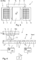
- Fig.1 is a transport device 1 in the form of a Langstatorlinearmotors exemplified.
- the transport device 1 consists of a number n of transport sections A1... A9 (generally An), which are assembled to the transport device 1.
- This modular design allows a very flexible design of the transport device 1, but also requires a plurality of transfer positions U1 ... U9, where the transported on the transport device 1 transport units T1 ... Tx (for reasons of clarity are in Fig.1 not all transport units are identified by a reference numeral) can be transferred from one transport section A1... A9 to another.
- the transport device 1 is designed as a long stator linear motor, in which the transport sections A1... A9 form a part of a long stator of a long stator linear motor in a manner known per se.
- a multiplicity of electrical drive coils are arranged in the longitudinal direction in a known manner (in FIG Fig.1 not shown for reasons of clarity), which with excitation magnets on the transport units T1 ... Tx (see Figure 3 ) interact.
- the electrical stator current i A of the individual drive coils 7 ... Tx generates 8 for each of the transport units T1 independently a propulsive force F v, the transport units T1 ...
- Each of the transport units T1 ... Tx can be moved individually (speed, acceleration, lane) and independently (except for the avoidance of possible collisions) from the other transport units T1 ... Tx.
- transfer positions U1 ... U10 are arranged. Different types of transfer positions U1... U10 are conceivable here.
- a switch is provided, while the other transfer positions U1, U3 ... U6, U8, U9 e.g. are executed as change points from one transport section A1 ... A8 to another.
- a transport unit T6 can for example be moved further on the transport section A2 or the transport section A3.
- a transport unit T5 is transferred from the unilateral transport section A1 to the unilateral transport section A2. The transfer from one transport section to another transport section can take place in any desired manner.
- the workstation S1 can be designed, for example, as a sluice-in and / or outfeed station, in which finished components are removed and components to be processed are transferred to a transport unit T1... Tx.
- any processing steps can be performed on the components.
- the transport units T1 ... Tx can be stopped in a workstation S1 ... S4 for processing, for example in a filling station, in which empty bottles are filled, or moved through, for example, in a temperature control in the components are temperature-treated, if necessary at a different speed than between the workstations S1 ... S4.
- FIG.2 Another example of a transport device 1 is in Fig.2 shown.
- the transport section A2 ... A4 serve here for the introduction of various components at the workstations S1 ... S3.
- a workstation S4 of a transport section A5 these components are interconnected or otherwise processed and discharged from the transport device 1.
- Another transport section A1 serves to transfer the components from the transport sections A2, A3, A4 into the transport section A5.
- transfer positions U1, U2, U3 are provided in order to transfer the transport units Tx with the various components into the transport section A1.
- a transfer position U4 is provided, in which the transport units Tx are transferred with the various components in the transport section A5.
- the transport device 1 can be made almost arbitrary and can be composed of different transport section A, and if necessary, transfer positions U and work stations S can be provided.
- Figure 3 shows a cross section through an arbitrary transport section An and a transport unit Tx moved thereon.
- a transport unit Tx consists of a base body 2 and a component receptacle 3 arranged thereon for receiving a component to be transported (not shown), the component receptacle 3 basically being able to be arranged at any point of the base body 2, in particular also on the underside for hanging components.
- the number of excitation magnets 4, 5 of the long stator linear motor is arranged on the base body 2, preferably on both sides of the transport unit Tx.
- the transport path of the transport device 1, or a transport section An is formed by a stationary guide structure 6, on which the drive coils 7, 8 of the long stator linear motor are arranged.
- the main body 2 with the permanent magnets arranged on both sides as excitation magnets 4, 5 is arranged between the drive coils 7, 8 in the embodiment shown.
- the transport unit Tx between the guide structure 6 with the drive coils 7, 8 and along the transport path is movable.
- guiding elements 9 may also be provided on the base body 2 and / or on the component receptacle 3 (not shown here for reasons of clarity), in order to transport the transport unit Tx along the To lead transport route.
- the guide elements 9 of the transport unit Tx act together for guidance with the stationary guide structure 6, e.g. in which the guide elements 9 are supported on the guide structure 6, slide on it or unroll, etc.
- the leadership of the transport unit Tx but can also be done by the provision of guide magnets.
- other arrangements of the drive coils 7, 8 and the cooperating excitation magnets 4, 5 are conceivable.
- excitation magnets may be provided on only one side of a transport unit Tx. In this case, drive coils on only one side of the transport unit Tx would be sufficient.
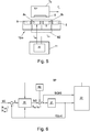
- a stator current i A is impressed in the drive coils 7, 8 in the region of the transport unit Tx ( Figure 4 ), wherein in different drive coils 7, 8 also different stator currents i A (in magnitude and vectorial direction) can be impressed. It is also sufficient only in the drive coils 7, 8 to impress a stator current i A , which can just interact with the excitation magnet 4, 5 on the transport unit Tx.
- a drive coil 7, 8 is energized with a stator current i A with a current component i Aq that generates a driving force.
- the drive coils 7, 8 arranged on both sides need not be energized at the same time by impressing a stator current i A. It is basically sufficient if the driving force F v acting on the transport unit Tx for movement is generated only by means of the drive coils 7, 8 of one side. At track sections of the transport route at which a large propulsion force F v is required, eg in the case of a gradient, a heavy load or in areas of acceleration of the transport unit Tx, the drive coils 7, 8 can be energized on both sides (eg transport section A9 in FIG Fig.1 ), whereby the driving force F v can be increased.
- a transport segment TS can each be controlled by an associated segment control unit 11, such as in the US 6,876,107 B2 described and in Fig. 4 is shown.
- a transport unit Tx which is located in a transport segment TSm, is therefore controlled by the associated segment control unit 11m.
- the segment control unit 11 m controls the drive coils 7, 8 of the associated transport segment TSm such that the transport unit Tx is moved in the desired manner (speed, acceleration) along the transport segment TSm by the generated propulsion force F V.
- a transport unit Tx moves from a transport segment TSm to the next transport segment TSm + 1, the control of the transport unit Tx is also transferred in an orderly manner to the segment control unit 11m + 1 of the next transport segment TSm + 1.
- the movement of the transport unit Tx by the transport device 1 can be monitored in a higher-level system control unit 10, which is connected to the segment control units 11.
- the system control unit 10 controls, for example, by position specifications s soll or speed specifications v soll the movement of the transport unit Tx by the transport device 1.
- the segment control units 11 then regulate a possible error between the target size and actual size by the drive coils 7, 8 of the transport segment TSm with a stator current i A be charged.
- each segment with its own segment control unit 11 for the drive coils 7, 8, wherein the segment control units 11 may also be connected to one another on each side via a data line and data, for example measured values of an actual variable, can be exchanged with one another.
- an actual variable such as an actual position s or an actual speed v
- Each segment control unit 11 generates from the setpoint specifications s soll or v soll and the actual variables s and v a stator current i A , with which the required drive coils 7, 8 are applied.
- a stator current i A is a current vector (current space vector) which comprises a propulsion-force-forming q-component i Aq for generating the propulsive force F v , and possibly also a lateral force-forming d-component i Ad , and which effects a magnetic flux ⁇ .
- a drive coil controller 20 is implemented in a segment control unit 11, which regulates all drive coils 7, 8 of the transport segment TSm, as in FIG Figure 5 shown.
- FIG 6 is the basic control concept and the basic inventive concept for identifying the controller parameters RP of a drive coil controller 20 of a drive coil 8a, 8b shown as a block diagram.
- the controlled system 21 essentially the technical system or the components between introducing the manipulated variable, for example in the form of the stator current i A and detecting (measuring, estimating, calculating) the actual size IG in the form of an actual position s or actual speed v of the transport unit Tx, ie in particular drive coils 8a, 8b, transport unit Tx with excitation magnet 5 and also the interaction of the transport unit Tx with the transport section An
- the drive coil controller 20 for each drive coil 8a, 8b in a conventional manner in a closed loop.
- an actual variable IG for example an actual position s or actual speed v of the transport unit Tx, is detected and returned in a known manner.
- the actual size IG can be measured, derived from other measured, calculated or known quantities or determined in a control-technical observer.
- the actual size IG can therefore be assumed to be known and can also be supplied to the drive coil controller 20, as in Figure 6 indicated.
- the drive coil controller 20 determines a manipulated variable StG, eg a stator current i Aa , i Ab for each drive coil 8a, 8b to be energized.
- the drive coil controller 20 may comprise a controller cascade of a position controller RL and a speed controller RV, as in Figure 7 shown. In itself but only a position controller RL or only a speed controller RV would be sufficient.
- the position controller RL calculates a speed v R to be adjusted from the desired value SG and the actual variable IG, from which the speed controller RV again calculates a driving force F R to be adjusted, wherein the actual variable IG can also be taken into account.
- This satisfiedegelnde driving force F R is finally converted in a conversion block 25 in the stator current i A as manipulated variable StG.
- the input driving force F R or the stator current i A to be regulated is also applied by all drive coils 7, 8 acting on the transport unit Tx.
- the dormitornde driving force F R is therefore still according to the current (known) position s of the transport unit Tx on the individual acting drive coils 7, 8 divide, as in Figure 8 is shown.
- the manipulated variable StG in the form of the stator current i A is divided in a current distribution unit 23 into the individual desired drive coil currents i Asoll ', i Asoll ", i Asoll “' of the acting drive coils 7, 8. From the current position is known at any time, what proportion each acting drive coil 7, 8 contributes.
- the single coil controller 24, or its parameters can be set in advance, or assumed to be known. For this reason, the individual coil controllers 24 are preferably also assigned to the controlled system 21, as in FIG Figure 8 shown. Likewise, the distribution of the manipulated variable StG in sizes of the individual acting drive coils 7, 8 is preferably assigned to the controlled system 21.
- the coil voltages u A ', u A ", u A "' of the acting drive coils 8 ', 8 ", 8'” are then applied to the motor hardware 26 of the long stator linear motor.
- the distribution of the manipulated variable StG in sizes of the individual acting drive coils 7, 8 could of course also be performed in the drive coil controller 20.
- the output of the drive coil controller 20 would then be a manipulated variable StG for each acting drive coil 7, 8.
- a plurality of excitation signals AS, just an excitation signal AS for each acting drive coil 7, 8, should be provided.
- the manipulated variables StG would just be voltages, which means that the starting signal AS is also a voltage. However, this does not change the inventive idea.
- the drive coil controller 20, or the controllers implemented therein has a number of controller parameters RP to be set, so that a stable and sufficiently dynamic regulation of the movement of the transport unit Tx is possible.
- the controller parameters RP are usually set once, usually before or during startup of the transport device 1, for example via the system control unit 10. It should be noted that the controller parameters of the individual coil controller 24 are not parameterized in the rule, since the single coil controller 24 essentially only from the concrete, known embodiment of the drive coils 7, 8 is dependent. These controller parameters of the single coil controllers 24 are therefore normally known and need not be changed. Consequently, the controller parameters of the controller units assigned to the transport unit Tx, ie, e.g. of the position controller RL and the speed controller RV.
- the determination of the controller parameters RP is difficult.
- the controlled path drive coils 7, 8, transport unit Tx with excitation magnets 4, 5
- the interaction of the transport unit Tx with the transport section An can change.
- Such a change may, for example, already result from the fact that the transport unit Tx is loaded with different loads.
- friction between the transport unit Tx and the guide structure 6 of the transport section An also has an effect, wherein the friction in turn may depend on the current state of wear of the transport unit Tx and the transport section A.
- operating parameters such as the current speed of the transport unit Tx or an ambient temperature, can act on the controlled system 21, for example by speed-dependent or temperature-dependent friction, and influence the control.
- the drive coil controller 20 can control robust and stable at these very different, fluctuating conditions in a wide range, the drive coil controller 20 had previously been designed to be very conservative about the controller parameters. This, however, reduces the dynamics of the controller, in the sense of rapid control interventions, such as rapid changes in speed. To improve this problem, the procedure according to the invention is as follows, wherein the Fig.5 and Fig.6 Reference is made.
- a measuring cell MZ is defined, wherein the measuring cell MZ comprises at least two drive coils 8a, 8b of one side, which interact with the transport unit Tx, preferably at least two adjacent drive coils 8a, 8b, as in FIG Figure 5 shown.
- the measuring cell MZ preferably comprises all drive coils 8 of a transport segment TSm or all drive coils 8 of several transport segments TSm.
- a coarse parameterization of the controller parameters RP is performed. This can be done on the basis of the known mass of the transport unit Tx (including the expected load) and the known design data of the long stator linear motor, the controller parameters RP are usually set so that the closed loop a greatly reduced bandwidth (low dynamics), However, a great robustness (high stability) has.
- various methods for controller parameterization are known, with which a rough parameterization can be performed. The rough parameterization is merely to ensure that the transport unit Tx can be moved and positioned without placing high demands on dynamics and accuracy. With this coarse parameterization, a specific operating point can be approached with the transport unit Tx by specifying a corresponding desired value SG.
- a specific position s (standstill of the transport unit Tx) or a specific speed v of the transport unit Tx is understood as the operating point.
- Start-up means, of course, that the operating point is approached in the region of the measuring cell MZ, ie that the transport unit Tx is moved through the measuring cell MZ at a certain speed, for example, or that the transport unit Tx is moved into the area of the measuring cell MZ and stopped therein.
- an excitation signal AS is introduced into the closed control loop by superposing the manipulated variable StG with the excitation signal AS.
- the starting signal AS is impressed on all drive coils 8a, 8b of the measuring cell MZ.
- the start signal AS comprises a specific, predetermined frequency band.
- Possible excitation signals AS are, for example, a known pseudo-random binary sequence signal (PRBS) or sine-sweep signal.
- PRBS pseudo-random binary sequence signal
- the frequencies in the excitation signal AS and the amplitudes of the excitation signal AS are chosen so that the system responses are sufficiently informative, ie that the system responses in the frequency range of interest are sufficiently large in order to be able to evaluate signal technology.
- a frequency range of interest is, in particular, the range in which resonance or antiresonance is expected.
- the amplitudes of the starting signal AS can be based on the rated current (or rated voltage) of the long stator linear motor and are typically in the range of 1/10 of the rated current (or rated voltage).
- the start signal AS should preferably be zero in the mean value, with which the controlled system (controlled system 21) itself remains as uninfluenced as possible on average.
- the desired movement of the transport unit Tx (given by the position specifications s soll or speed specifications v soll for starting the operating point) is superimposed on an excitation movement, which is only possible if the measuring cell MZ comprises at least two drive coils 8a, 8b.
- the control variable StGAS superposed with the starting signal AS and the response of the controlled system 21 to this excitation, which corresponds to the actual quantity IG, are fed to an evaluation unit 22.
- the response of the controlled system 21 is of course the current state of motion of the transport unit Tx in the form of the actual position s or actual speed v.
- the response of the controlled system 21 can be measured directly, derived from other measured variables or can also be calculated by an observer or otherwise estimated.
- the frequency response (with amplitude response and phase response) is determined in a known manner from the control variable StGAS superimposed with the excitation signal AS and the response of the controlled system 21, typically by filtering and discrete Fourier transformation of the two signals and subsequent element-wise division of the two Signals according to the scheme output divided by input.
- the frequency response can be determined for the open and / or closed loop.
- the starting signal AS must be impressed, for the determination of the controller parameters RP but only the superimposed control variable StGAS one of the drive coils 8a, 8b of the measuring cell MZ must be evaluated.
- the frequency response is referred to below, this is the frequency response associated with the transport unit Tx and a drive coil 8a, 8b cooperating with the transport unit Tx.
- the frequency response can serve as a basis for determining the optimal controller parameters RP.
- the controller parameters RP are varied in order to set a specific property of the frequency response in the desired manner.
- One known method is, for example, the Maximum Peak Criteria.
- the Maximum Peak Criteria method is based on the Figure 9 exemplified in more detail. Therein is the frequency response in the form of the amplitude response ( 9a above) and the phase response ( 9b below), each for the open (dashed) and closed loop.
- the open loop is known to be the consideration without feedback of the actual size IG to the target size SG.
- the controller parameters RP are now varied at maximum peak criteria so that the maximum value of the amplitude response of the closed loop does not exceed a certain, predetermined value MT.
- This value MT results, for example, from desired limits for the gain and phase margin of the open loop. This ensures that the open loop has sufficient phase margin PM (phase ⁇ at gain zero dB) and gain margin GM (gain G at phase -180 °).
- phase margin PM phase ⁇ at gain zero dB
- GM gain G at phase -180 °.
- different controller parameters RP are to be varied, such as a gain and a reset time in a PI controller.
- controller parameters RP there are also various methods for varying the controller parameters RP. For example, an optimization problem could be formulated to minimize the distance of the maximum of the closed loop amplitude response to the value MT.
- controller parameters RP are obtained for the respective transport unit Tx.
- These controller parameters RP can now also be used for the same transport units Tx.
- the determination of the controller parameters RP can also be carried out for different operating points and / or different loads of the transport unit Tx.
- the controller parameters RP for a transport unit Tx can also be determined for different measuring cells MZ.
- the controller parameter set may be selected that best matches the current load carried by a transport unit Tx or that best fits the current speed or position of the transport unit Tx.
- one or more controller parameter sets can be created for each transport unit Tx.
- consideration can also be given to the differences between the various transport units Tx.
- the frequency response also includes other essential characteristics of the controlled system 21.
- the current total mass m G of the transport unit Tx can be determined during operation from the amplitude response. This in turn makes it possible to conclude a loading of the transport unit Tx, since the mass m Tx of the transport unit Tx is known. Any difference must therefore be attributed to the load, with which the load can be determined. In the case of a known load, it would then be possible again to select, for example, the suitable controller parameter set for optimal regulation of the transport unit Tx.
- a controlled system 21 can be classified as rigid if the resonance / antiresonance pair with the lowest frequency values (f R , f AR ) is significantly greater than the phase frequency f D.
- the phase passage frequency f D is known to be the frequency at which the phase ⁇ of the open loop intersects the value -180 ° the first time.
- the controlled system would be stiff if the frequency values (f R , f AR ) of the resonant / antiresonant pair are in the range of the phase frequency f D and flexible if the frequency values (f R , f AR ) of the resonant / antiresonant pair are significantly smaller than the phase transmission frequency f D.
- it is decided whether the resonance / anti-resonance frequencies (f R , f AR ) are disturbing and with what measures they are eliminated or damped, for example by means of a suitable filter.
- the controller parameterization and / or the determination of the characteristics of the controlled system 21 can also be repeated during ongoing operation at certain intervals.
- the drive coil controller 20 can be continuously adapted to the changing state of wear of the transport unit Tx and thus to a changing controlled system 21.
- the controller parameterization can for example be performed every day before switching off the transport device 1 or before the commissioning of the transport device 1.
- the determined controller parameters RP could then be checked for plausibility.
- the operating point used for the controller parameterization could be approached with the drive coil controller 20 with the determined optimum controller parameters RP be switched back and the start signal AS.
- the frequency response of the closed loop is again determined and based on its maximum resonance peak decided whether the behavior of the closed loop is satisfactory.
- a plurality of measuring cells MZ may be provided.
- different optimal controller parameters RP can be determined for different sections of the transport path.
- the determined controller parameters RP for a transport unit Tx preferably always apply from a first measuring cell MZ1 to the next measuring cell MZ2.
- the controlled system 21 can now also be analyzed with regard to further system parameters of interest for the process.
- the controller parameters RP of the drive coil controller 20 can be used e.g. can be identified as described above, but can also be determined otherwise or may also be known. Basically, the only requirement is that a predetermined motion profile can be traversed with the drive coil controller 20. The movement profile should stimulate the controlled system 21 sufficiently to be able to identify the system parameters.
- a transport unit Tx is given a certain movement profile, e.g. in the form of a temporal course of different speeds and accelerations (also in the sense of delays), given. It is advantageous if movements are contained in both directions to detect direction-dependent system parameters.
- This movement profile, as desired variables of the control, is traversed by the transport unit Tx under control of the drive coil controller 20.
- the drive coil controller 20 generates control variables StG in accordance with the motion profile, which act on the controlled system 21 and effect actual variables IG of the controlled system 21, which act back on the setpoint variables SG in the closed control loop.
- ⁇ p denotes the magnetic flux produced by the excitation magnets 4, 5 and linked to the drive coil 7, 8
- T P corresponds to the pole width of the excitation magnets of the transport unit Tx
- x denotes the position of the transport unit Tx.
- L Ad and L Aq denote the known inductances of the drive coil 7, 8 in d- and q-direction.
- the system parameters of the model of the controlled system 21, in this case the total mass m G of the transport unit Tx, the coefficients kv for the viscous friction, the coefficients ks and for the static friction, can be determined by assuming a known motor constant K f Determine parameter estimation method. If another system parameter is known, eg the total mass m G as described above, the engine constant K f can also be estimated therefrom.
- K f the motor constant
- K f the predetermined motion profile is traversed, whereby the velocity v (or equivalently the position s) and the acceleration dV dt is defined as input to the parameter estimation method.
- the stator current i Aq set at a drive coil 7, 8 corresponds to the manipulated variable StG and is known or can also be detected, eg measured, in another way.
- the stator current i Aq is calculated from the model of the controlled system 21 and the error (eg the mean square error) between the calculated and the measured stator current is minimized by varying the system parameters of the model.
- Known parameter estimation methods include the Least Square method, the Recursive Least Square method, a Kalman or Extended Kalman filter.
- the system parameters determined thereby identify the controlled system 21, ie in particular also the transport path or a transport section An or a transport segment TSm via the coefficients kv for the viscous friction and the coefficient ks for the static friction, as well as the air gap between excitation magnet 4, 5 and the drive coil 7, 8 via the parameter K f .
- the time course of these system parameters can be drawn on the state of wear of the transport unit Tx and / or the transport route, in particular the transport section An or a transport segment TSm.
- the system parameters of the controlled system 21 are determined regularly, eg once every day, then from their temporal change from the coefficient kv for the viscous friction and the coefficient ks for the static friction, a possible wear can be concluded. If these coefficients increase, then this is an indication of progressive wear. Likewise, a change in the air gap can be detected from the motor constant K f , which may also indicate progressive wear. In the case of impermissible changes, for example, determined by exceeding a predetermined limit, maintenance of the transport unit Tx and / or the transport section An can also be initiated.
- the drive coil controller 20 can also be supplemented by a feedforward control V.
- the precontrol V acts (eg by addition) on the input of the drive coil controller 20.
- This is in Figure 10 illustrated by the example of a cascaded drive coil controller 20.
- the precontrol V acts (eg by addition) in each case on the input of the associated controller, ie a speed precontrol v VS on the input of the speed controller RV and a force precontrol F VS on the input of the conversion block 25.
- the feedforward V can in a conventional manner on a Model of the controlled system 21 are based, with the inverse of the model of the controlled system 21 is used as the feedforward V in the rule.
- the model is preferably implemented in the form of equations of motion of the transport unit Tx, as stated above.
- the model is determined by the identified system parameters, which also determines the feedforward (as inverse of the model). Instead of a model of the controlled system 21, however, it is also possible to implement any other feedforward control law.
- v VS ds dt .
- IG actual variable
- the speed controller RV only controls more non-linearities, unknown external influences and disturbance variables which are not regulated by the speed precontrol V VS.
- F VS m G dv dt + kv ⁇ v + ks ⁇ sign v . with the viscosity coefficient kv for the viscous friction, the coefficient ks for the static friction, the current speed of the transport unit Tx and the sign function sign.
- the conversion block 25 calculates the manipulated variable StG for a drive coil 7, 8, for example in the form of the stator current i A to be set .
- the current controller RS controls with a force precontrol only more nonlinearities, unknown external influences and disturbances, which are not controlled by the force precontrol.
- the drive coil controller 20 can be supplemented in a known manner by a guide-smoothing filter FF, even without feedforward V, as in Figure 10 shown.
- the guidance smoothing filter FF can be implemented from a control engineering point of view, for example as a finite impulse response (FIR) filter with a time constant T.
- the guide smoothing filter FF is used to filter the target quantity SG to prevent the excitation of certain unwanted frequencies.
- the guidance smoothing filter FF could be implemented as jerk limitation (with the jerk as time derivative of the acceleration).
- the target quantity SG F filtered by the guide smoothing filter FF is then used for the feedforward control V and the control by the drive coil controller 20.
- the following error behavior (difference between the target movement profile and the actual movement profile) can be evaluated at the end of this movement profile.
- the time constant T of the guide smoothing filter FF which corresponds to the period duration, can then be calculated in a known manner.
- the determination of the system parameters of the model of the controlled system 21 and / or the parameters of the guidance smoothing filter FF are of course dependent on the route due to the specification of the motion profile. This can also properties of the transport route derived, such as static or dynamic friction parameters. On the basis of these properties of the transport route, in particular on the basis of the temporal change of these properties, it is therefore also possible to draw conclusions about the condition of the transport route. If the same properties are determined on the same transport route for different transport units Tx, a comparison of the properties can also be made to the (wear) state of the transport unit Tx.
- the imprinting of a movement profile for determining the system parameters and / or parameters of the guidance smoothing filter FF preferably takes place on a transport path along which no high demands are placed on the movement of the transport unit Tx (speed specification, position specification).
Applications Claiming Priority (1)
| Application Number | Priority Date | Filing Date | Title |
|---|---|---|---|
| ATA50494/2016A AT518734B1 (de) | 2016-05-31 | 2016-05-31 | Verfahren zum Betreiben eines Langstatorlinearmotors |
Publications (1)
| Publication Number | Publication Date |
|---|---|
| EP3251985A1 true EP3251985A1 (fr) | 2017-12-06 |
Family
ID=58765756
Family Applications (1)
| Application Number | Title | Priority Date | Filing Date |
|---|---|---|---|
| EP17172343.0A Withdrawn EP3251985A1 (fr) | 2016-05-31 | 2017-05-23 | Procédé de fonctionnement d'un moteur linéaire à stator déployé |
Country Status (5)
| Country | Link |
|---|---|
| US (1) | US10554111B2 (fr) |
| EP (1) | EP3251985A1 (fr) |
| CN (1) | CN107453679B (fr) |
| AT (1) | AT518734B1 (fr) |
| CA (1) | CA2968931A1 (fr) |
Cited By (2)
| Publication number | Priority date | Publication date | Assignee | Title |
|---|---|---|---|---|
| WO2022117524A3 (fr) * | 2020-12-01 | 2022-12-15 | B&R Industrial Automation GmbH | Dispositif de transport sous la forme d'un moteur linéaire à stator long |
| EP4230469A1 (fr) * | 2022-02-22 | 2023-08-23 | Siemens Aktiengesellschaft | Procédé de détermination d'une fente d'aération entre un rotor de transport et un segment de stator à l'aide d'un appareil d'automatisation |
Families Citing this family (9)
| Publication number | Priority date | Publication date | Assignee | Title |
|---|---|---|---|---|
| US11165372B2 (en) * | 2017-09-13 | 2021-11-02 | Rockwell Automation Technologies, Inc. | Method and apparatus to characterize loads in a linear synchronous motor system |
| EP3517344A1 (fr) * | 2018-01-24 | 2019-07-31 | B&R Industrial Automation GmbH | Unité de transport pour un moteur linéaire à stator long |
| DE102018209723A1 (de) * | 2018-06-15 | 2019-12-19 | Krones Ag | Verfahren und Vorrichtung zur Verschleißüberwachung eines Langstator-Linearmotor-Systems |
| DE102018209725A1 (de) | 2018-06-15 | 2019-12-19 | Krones Ag | Verfahren und Vorrichtung zur Lastidentifikation eines Transportelements eines Langstator-Linearmotorsystems |
| EP3599127B1 (fr) * | 2018-07-25 | 2022-10-05 | B&R Industrial Automation GmbH | Procédé de fonctionnement d'un moteur linéaire à stator long pourvu d'unités de transport et surveillance de collision |
| EP3653428A1 (fr) * | 2018-11-19 | 2020-05-20 | B&R Industrial Automation GmbH | Procédé de surveillance sûre du fonctionnement d'un moteur linéaire à stator long |
| EP3706297A1 (fr) * | 2019-03-07 | 2020-09-09 | B&R Industrial Automation GmbH | Procédé de commande d'un moteur linéaire à stator long |
| US11718482B2 (en) * | 2020-08-31 | 2023-08-08 | Rockwell Automation Technologies, Inc. | System and method of monitoring disturbance force in an independent cart system, compensation of said disturbance force |
| US11757342B2 (en) * | 2021-09-15 | 2023-09-12 | Rockwell Automation Technologies, Inc. | Wear indicator for track and mover system |
Citations (2)
| Publication number | Priority date | Publication date | Assignee | Title |
|---|---|---|---|---|
| US20130313072A1 (en) * | 2011-02-07 | 2013-11-28 | Robert Bosch Gmbh | Transport device with identification function |
| WO2015036194A1 (fr) * | 2013-09-13 | 2015-03-19 | Krones Ag | Dispositif et procédé pour assurer la maintenance d'éléments de transport dans un système de traitement de contenants |
Family Cites Families (13)
| Publication number | Priority date | Publication date | Assignee | Title |
|---|---|---|---|---|
| FR1596424A (fr) | 1968-12-26 | 1970-06-15 | ||
| US6208497B1 (en) * | 1997-06-26 | 2001-03-27 | Venture Scientifics, Llc | System and method for servo control of nonlinear electromagnetic actuators |
| US6101952A (en) | 1997-12-24 | 2000-08-15 | Magnemotion, Inc. | Vehicle guidance and switching via magnetic forces |
| AU2003248622A1 (en) | 2002-06-05 | 2003-12-22 | Jacobs Automation Llc | Controlled motion system |
| DE112004000787A5 (de) | 2003-05-21 | 2008-02-28 | Schierholz-Translift Schweiz Ag | Schienenanordnung, Weiche und Transportvorrichtung mit magnetostriktiven Sensoren |
| US9032880B2 (en) | 2009-01-23 | 2015-05-19 | Magnemotion, Inc. | Transport system powered by short block linear synchronous motors and switching mechanism |
| DE102011075174A1 (de) | 2011-05-03 | 2012-11-08 | Robert Bosch Gmbh | Transfereinrichtung für Gegenstände |
| WO2012172657A1 (fr) * | 2011-06-15 | 2012-12-20 | 株式会社安川電機 | Système de transfert |
| DE102012204919A1 (de) | 2012-03-27 | 2013-10-02 | Beckhoff Automation Gmbh | Statorvorrichtung für einen linearmotor und lineares transportsystem |
| DE102012025326B4 (de) * | 2012-12-22 | 2022-01-20 | Festo Se & Co. Kg | Verfahren zum Betreiben eines elektromagnetischen Transportsystems und elektromagnetisches Transportsystem |
| DE102013218389B4 (de) | 2013-09-13 | 2023-01-12 | Krones Ag | Vorrichtung und Verfahren zum Schalten einer passiven Weiche für Transportsysteme mit Linearmotoren |
| CN105813886B (zh) | 2013-09-21 | 2018-04-03 | 麦克纳莫绅有限公司 | 用于包装和其它用途的线性电机运输 |
| JP6313642B2 (ja) * | 2014-04-18 | 2018-04-18 | キヤノン株式会社 | リニアモータ制御装置及びリニアモータ制御システム |
-
2016
- 2016-05-31 AT ATA50494/2016A patent/AT518734B1/de not_active IP Right Cessation
-
2017
- 2017-05-23 EP EP17172343.0A patent/EP3251985A1/fr not_active Withdrawn
- 2017-05-30 US US15/608,095 patent/US10554111B2/en active Active
- 2017-05-31 CA CA2968931A patent/CA2968931A1/fr not_active Abandoned
- 2017-05-31 CN CN201710405059.2A patent/CN107453679B/zh active Active
Patent Citations (2)
| Publication number | Priority date | Publication date | Assignee | Title |
|---|---|---|---|---|
| US20130313072A1 (en) * | 2011-02-07 | 2013-11-28 | Robert Bosch Gmbh | Transport device with identification function |
| WO2015036194A1 (fr) * | 2013-09-13 | 2015-03-19 | Krones Ag | Dispositif et procédé pour assurer la maintenance d'éléments de transport dans un système de traitement de contenants |
Cited By (2)
| Publication number | Priority date | Publication date | Assignee | Title |
|---|---|---|---|---|
| WO2022117524A3 (fr) * | 2020-12-01 | 2022-12-15 | B&R Industrial Automation GmbH | Dispositif de transport sous la forme d'un moteur linéaire à stator long |
| EP4230469A1 (fr) * | 2022-02-22 | 2023-08-23 | Siemens Aktiengesellschaft | Procédé de détermination d'une fente d'aération entre un rotor de transport et un segment de stator à l'aide d'un appareil d'automatisation |
Also Published As
| Publication number | Publication date |
|---|---|
| CN107453679A (zh) | 2017-12-08 |
| US10554111B2 (en) | 2020-02-04 |
| US20170346380A1 (en) | 2017-11-30 |
| AT518734B1 (de) | 2018-05-15 |
| CN107453679B (zh) | 2023-02-21 |
| AT518734A1 (de) | 2017-12-15 |
| CA2968931A1 (fr) | 2017-11-30 |
Similar Documents
| Publication | Publication Date | Title |
|---|---|---|
| EP3251986B1 (fr) | Procédé de fonctionnement d'un moteur linéaire à stator déployé | |
| AT518734B1 (de) | Verfahren zum Betreiben eines Langstatorlinearmotors | |
| EP3978300B1 (fr) | Procédé de réglage de la force normale d'une unité de transport d'un moteur linéaire à stator longs | |
| EP3379719B1 (fr) | Procédé destinés à transferer une unité de transport à une position de transmission | |
| EP3547530B1 (fr) | Procédé de fonctionnement d'un dispositif de transport en forme de moteur linéaire à stator long | |
| EP3385803B1 (fr) | Procédé de fonctionnement d'un moteur linéaire à stator déployé | |
| EP3807605B1 (fr) | Procédé et dispositif d'identification d'une charge d'un élément de transport d'un système à moteur linéaire à stator long | |
| EP3341803A1 (fr) | Procédé de commande et/ou de régulation d'un dispositif d'entraînement linéaire, dispositif de commande, dispositif d'entraînement linéaire et installation | |
| WO2015140155A1 (fr) | Dispositif de transport pour déplacer et/ou positionner des objets | |
| WO2008090129A2 (fr) | Procédé et dispositif de commande d'entraînement d'un véhicule à sustentation magnétique sur une ligne ferroviaire à sustentation magnétique | |
| EP4121316B1 (fr) | Transmission d'énergie dans un système de transport linéaire | |
| EP1864370A1 (fr) | Moteur lineaire et procede pour faire fonctionner un moteur lineaire | |
| EP3363751B1 (fr) | Procédé de transfert d'une unité de transport d'un convoyeur à moteur linéaire à une position de transfert | |
| DE3411190C2 (de) | Magnetregler für Langstator-Magnetschwebefahrzeuge | |
| DE2446936A1 (de) | Regelanordnung zur dynamischen entkopplung eines schienengebundenen fahrzeuges, das gegenueber seinen schienen mit hilfe von magneten in einem abstand gefuehrt ist | |
| DE3501487C2 (fr) | ||
| DE2446851A1 (de) | Regelanordnung zur dynamischen entkopplung eines schienengebundenen fahrzeuges von seinen schienen, das gegenueber seinen schienen mit hilfe von magnetenin einem abstand gefuehrt ist | |
| WO2023213701A1 (fr) | Procédé et dispositif permettant de surveiller le fonctionnement d'un dispositif de transport | |
| EP3531552A1 (fr) | Procédé de fonctionnement d'un système de transport à base du moteur linéaire | |
| WO2024047193A1 (fr) | Procédé de commande du mouvement d'un axe d'entraînement d'une unité d'entraînement | |
| DE903716C (de) | Verfahren zur Regelung der Leistungsverteilung auf mehrere miteinander gekuppelte Kraftwerke bzw. Netze |
Legal Events
| Date | Code | Title | Description |
|---|---|---|---|
| PUAI | Public reference made under article 153(3) epc to a published international application that has entered the european phase |
Free format text: ORIGINAL CODE: 0009012 |
|
| AK | Designated contracting states |
Kind code of ref document: A1 Designated state(s): AL AT BE BG CH CY CZ DE DK EE ES FI FR GB GR HR HU IE IS IT LI LT LU LV MC MK MT NL NO PL PT RO RS SE SI SK SM TR |
|
| AX | Request for extension of the european patent |
Extension state: BA ME |
|
| 17P | Request for examination filed |
Effective date: 20180523 |
|
| RBV | Designated contracting states (corrected) |
Designated state(s): AL AT BE BG CH CY CZ DE DK EE ES FI FR GB GR HR HU IE IS IT LI LT LU LV MC MK MT NL NO PL PT RO RS SE SI SK SM TR |
|
| 17Q | First examination report despatched |
Effective date: 20180719 |
|
| STAA | Information on the status of an ep patent application or granted ep patent |
Free format text: STATUS: THE APPLICATION IS DEEMED TO BE WITHDRAWN |
|
| 18D | Application deemed to be withdrawn |
Effective date: 20191203 |