EP3251887A1 - Control device for electric vehicle and control method for electric vehicle - Google Patents
Control device for electric vehicle and control method for electric vehicle Download PDFInfo
- Publication number
- EP3251887A1 EP3251887A1 EP15879875.1A EP15879875A EP3251887A1 EP 3251887 A1 EP3251887 A1 EP 3251887A1 EP 15879875 A EP15879875 A EP 15879875A EP 3251887 A1 EP3251887 A1 EP 3251887A1
- Authority
- EP
- European Patent Office
- Prior art keywords
- torque
- vehicle
- electric motor
- motor vehicle
- value
- Prior art date
- Legal status (The legal status is an assumption and is not a legal conclusion. Google has not performed a legal analysis and makes no representation as to the accuracy of the status listed.)
- Granted
Links
- 238000000034 method Methods 0.000 title claims description 56
- 230000001172 regenerating effect Effects 0.000 claims abstract description 23
- 230000009467 reduction Effects 0.000 claims abstract description 13
- 238000013016 damping Methods 0.000 claims description 43
- 230000005540 biological transmission Effects 0.000 claims description 40
- 238000012937 correction Methods 0.000 claims description 40
- 238000004364 calculation method Methods 0.000 claims description 16
- 230000004043 responsiveness Effects 0.000 claims description 4
- 238000010586 diagram Methods 0.000 description 35
- 230000008569 process Effects 0.000 description 34
- 230000001133 acceleration Effects 0.000 description 11
- 239000012530 fluid Substances 0.000 description 10
- 230000033001 locomotion Effects 0.000 description 10
- 238000001914 filtration Methods 0.000 description 7
- 230000004044 response Effects 0.000 description 6
- 238000005096 rolling process Methods 0.000 description 3
- 230000000052 comparative effect Effects 0.000 description 2
- 238000001514 detection method Methods 0.000 description 2
- 230000008929 regeneration Effects 0.000 description 2
- 238000011069 regeneration method Methods 0.000 description 2
- 238000004088 simulation Methods 0.000 description 2
- 238000012546 transfer Methods 0.000 description 2
- 230000009471 action Effects 0.000 description 1
- 238000013459 approach Methods 0.000 description 1
- 238000004422 calculation algorithm Methods 0.000 description 1
- 230000008859 change Effects 0.000 description 1
- 238000006243 chemical reaction Methods 0.000 description 1
- 239000003638 chemical reducing agent Substances 0.000 description 1
- 230000000295 complement effect Effects 0.000 description 1
- 230000003247 decreasing effect Effects 0.000 description 1
- 230000000994 depressogenic effect Effects 0.000 description 1
- 238000013461 design Methods 0.000 description 1
- 230000000694 effects Effects 0.000 description 1
- 239000000446 fuel Substances 0.000 description 1
- 238000012986 modification Methods 0.000 description 1
- 230000004048 modification Effects 0.000 description 1
- 239000000047 product Substances 0.000 description 1
- 230000000452 restraining effect Effects 0.000 description 1
- 239000004065 semiconductor Substances 0.000 description 1
- 239000013589 supplement Substances 0.000 description 1
- 230000003313 weakening effect Effects 0.000 description 1
Images


Classifications
-
- B—PERFORMING OPERATIONS; TRANSPORTING
- B60—VEHICLES IN GENERAL
- B60L—PROPULSION OF ELECTRICALLY-PROPELLED VEHICLES; SUPPLYING ELECTRIC POWER FOR AUXILIARY EQUIPMENT OF ELECTRICALLY-PROPELLED VEHICLES; ELECTRODYNAMIC BRAKE SYSTEMS FOR VEHICLES IN GENERAL; MAGNETIC SUSPENSION OR LEVITATION FOR VEHICLES; MONITORING OPERATING VARIABLES OF ELECTRICALLY-PROPELLED VEHICLES; ELECTRIC SAFETY DEVICES FOR ELECTRICALLY-PROPELLED VEHICLES
- B60L15/00—Methods, circuits, or devices for controlling the traction-motor speed of electrically-propelled vehicles
- B60L15/20—Methods, circuits, or devices for controlling the traction-motor speed of electrically-propelled vehicles for control of the vehicle or its driving motor to achieve a desired performance, e.g. speed, torque, programmed variation of speed
-
- B—PERFORMING OPERATIONS; TRANSPORTING
- B60—VEHICLES IN GENERAL
- B60L—PROPULSION OF ELECTRICALLY-PROPELLED VEHICLES; SUPPLYING ELECTRIC POWER FOR AUXILIARY EQUIPMENT OF ELECTRICALLY-PROPELLED VEHICLES; ELECTRODYNAMIC BRAKE SYSTEMS FOR VEHICLES IN GENERAL; MAGNETIC SUSPENSION OR LEVITATION FOR VEHICLES; MONITORING OPERATING VARIABLES OF ELECTRICALLY-PROPELLED VEHICLES; ELECTRIC SAFETY DEVICES FOR ELECTRICALLY-PROPELLED VEHICLES
- B60L7/00—Electrodynamic brake systems for vehicles in general
- B60L7/10—Dynamic electric regenerative braking
- B60L7/14—Dynamic electric regenerative braking for vehicles propelled by ac motors
-
- B—PERFORMING OPERATIONS; TRANSPORTING
- B60—VEHICLES IN GENERAL
- B60L—PROPULSION OF ELECTRICALLY-PROPELLED VEHICLES; SUPPLYING ELECTRIC POWER FOR AUXILIARY EQUIPMENT OF ELECTRICALLY-PROPELLED VEHICLES; ELECTRODYNAMIC BRAKE SYSTEMS FOR VEHICLES IN GENERAL; MAGNETIC SUSPENSION OR LEVITATION FOR VEHICLES; MONITORING OPERATING VARIABLES OF ELECTRICALLY-PROPELLED VEHICLES; ELECTRIC SAFETY DEVICES FOR ELECTRICALLY-PROPELLED VEHICLES
- B60L15/00—Methods, circuits, or devices for controlling the traction-motor speed of electrically-propelled vehicles
- B60L15/20—Methods, circuits, or devices for controlling the traction-motor speed of electrically-propelled vehicles for control of the vehicle or its driving motor to achieve a desired performance, e.g. speed, torque, programmed variation of speed
- B60L15/2009—Methods, circuits, or devices for controlling the traction-motor speed of electrically-propelled vehicles for control of the vehicle or its driving motor to achieve a desired performance, e.g. speed, torque, programmed variation of speed for braking
-
- B—PERFORMING OPERATIONS; TRANSPORTING
- B60—VEHICLES IN GENERAL
- B60L—PROPULSION OF ELECTRICALLY-PROPELLED VEHICLES; SUPPLYING ELECTRIC POWER FOR AUXILIARY EQUIPMENT OF ELECTRICALLY-PROPELLED VEHICLES; ELECTRODYNAMIC BRAKE SYSTEMS FOR VEHICLES IN GENERAL; MAGNETIC SUSPENSION OR LEVITATION FOR VEHICLES; MONITORING OPERATING VARIABLES OF ELECTRICALLY-PROPELLED VEHICLES; ELECTRIC SAFETY DEVICES FOR ELECTRICALLY-PROPELLED VEHICLES
- B60L7/00—Electrodynamic brake systems for vehicles in general
- B60L7/22—Dynamic electric resistor braking, combined with dynamic electric regenerative braking
-
- B—PERFORMING OPERATIONS; TRANSPORTING
- B60—VEHICLES IN GENERAL
- B60L—PROPULSION OF ELECTRICALLY-PROPELLED VEHICLES; SUPPLYING ELECTRIC POWER FOR AUXILIARY EQUIPMENT OF ELECTRICALLY-PROPELLED VEHICLES; ELECTRODYNAMIC BRAKE SYSTEMS FOR VEHICLES IN GENERAL; MAGNETIC SUSPENSION OR LEVITATION FOR VEHICLES; MONITORING OPERATING VARIABLES OF ELECTRICALLY-PROPELLED VEHICLES; ELECTRIC SAFETY DEVICES FOR ELECTRICALLY-PROPELLED VEHICLES
- B60L2240/00—Control parameters of input or output; Target parameters
- B60L2240/10—Vehicle control parameters
- B60L2240/12—Speed
-
- B—PERFORMING OPERATIONS; TRANSPORTING
- B60—VEHICLES IN GENERAL
- B60L—PROPULSION OF ELECTRICALLY-PROPELLED VEHICLES; SUPPLYING ELECTRIC POWER FOR AUXILIARY EQUIPMENT OF ELECTRICALLY-PROPELLED VEHICLES; ELECTRODYNAMIC BRAKE SYSTEMS FOR VEHICLES IN GENERAL; MAGNETIC SUSPENSION OR LEVITATION FOR VEHICLES; MONITORING OPERATING VARIABLES OF ELECTRICALLY-PROPELLED VEHICLES; ELECTRIC SAFETY DEVICES FOR ELECTRICALLY-PROPELLED VEHICLES
- B60L2240/00—Control parameters of input or output; Target parameters
- B60L2240/40—Drive Train control parameters
- B60L2240/42—Drive Train control parameters related to electric machines
- B60L2240/423—Torque
-
- B—PERFORMING OPERATIONS; TRANSPORTING
- B60—VEHICLES IN GENERAL
- B60L—PROPULSION OF ELECTRICALLY-PROPELLED VEHICLES; SUPPLYING ELECTRIC POWER FOR AUXILIARY EQUIPMENT OF ELECTRICALLY-PROPELLED VEHICLES; ELECTRODYNAMIC BRAKE SYSTEMS FOR VEHICLES IN GENERAL; MAGNETIC SUSPENSION OR LEVITATION FOR VEHICLES; MONITORING OPERATING VARIABLES OF ELECTRICALLY-PROPELLED VEHICLES; ELECTRIC SAFETY DEVICES FOR ELECTRICALLY-PROPELLED VEHICLES
- B60L2250/00—Driver interactions
- B60L2250/26—Driver interactions by pedal actuation
- B60L2250/28—Accelerator pedal thresholds
-
- B—PERFORMING OPERATIONS; TRANSPORTING
- B60—VEHICLES IN GENERAL
- B60L—PROPULSION OF ELECTRICALLY-PROPELLED VEHICLES; SUPPLYING ELECTRIC POWER FOR AUXILIARY EQUIPMENT OF ELECTRICALLY-PROPELLED VEHICLES; ELECTRODYNAMIC BRAKE SYSTEMS FOR VEHICLES IN GENERAL; MAGNETIC SUSPENSION OR LEVITATION FOR VEHICLES; MONITORING OPERATING VARIABLES OF ELECTRICALLY-PROPELLED VEHICLES; ELECTRIC SAFETY DEVICES FOR ELECTRICALLY-PROPELLED VEHICLES
- B60L2260/00—Operating Modes
- B60L2260/40—Control modes
- B60L2260/42—Control modes by adaptive correction
-
- B—PERFORMING OPERATIONS; TRANSPORTING
- B60—VEHICLES IN GENERAL
- B60Y—INDEXING SCHEME RELATING TO ASPECTS CROSS-CUTTING VEHICLE TECHNOLOGY
- B60Y2200/00—Type of vehicle
- B60Y2200/90—Vehicles comprising electric prime movers
- B60Y2200/91—Electric vehicles
-
- B—PERFORMING OPERATIONS; TRANSPORTING
- B60—VEHICLES IN GENERAL
- B60Y—INDEXING SCHEME RELATING TO ASPECTS CROSS-CUTTING VEHICLE TECHNOLOGY
- B60Y2400/00—Special features of vehicle units
- B60Y2400/30—Sensors
- B60Y2400/303—Speed sensors
-
- Y—GENERAL TAGGING OF NEW TECHNOLOGICAL DEVELOPMENTS; GENERAL TAGGING OF CROSS-SECTIONAL TECHNOLOGIES SPANNING OVER SEVERAL SECTIONS OF THE IPC; TECHNICAL SUBJECTS COVERED BY FORMER USPC CROSS-REFERENCE ART COLLECTIONS [XRACs] AND DIGESTS
- Y02—TECHNOLOGIES OR APPLICATIONS FOR MITIGATION OR ADAPTATION AGAINST CLIMATE CHANGE
- Y02T—CLIMATE CHANGE MITIGATION TECHNOLOGIES RELATED TO TRANSPORTATION
- Y02T10/00—Road transport of goods or passengers
- Y02T10/60—Other road transportation technologies with climate change mitigation effect
- Y02T10/72—Electric energy management in electromobility
Definitions
- the present invention relates to a control device for electric motor vehicle and a control method for electric motor vehicle.
- a regenerative brake control device for electric vehicles provided with setting means capable of any given setting of a regenerative braking force of a motor and regenerates the motor by a regenerative braking force set by the setting means is known (see JP8-79907A ).
- JP8-79907A has the following problem. If the regenerative braking force set by the setting means is large, vibration in a longitudinal direction of a vehicle body may be generated when the electric vehicle is decelerated by the set regenerative braking force and the speed becomes 0.
- An object of the present invention is to provide a technique that reduces the generation of vibration in a longitudinal direction of a vehicle body in stopping an electric motor vehicle with a regenerative braking force.
- a device for controlling an electric vehicle is that a control device for electric motor vehicle uses the motor as the traveling driving source.
- the control device for electric motor vehicle is configured to decelerate by the regenerative braking force from the motor.
- the control device for electric motor vehicle is configured to detect the amount of the accelerator operation, detect the motor rotation speed proportionate to the traveling speed of the electric motor vehicle, and calculate the motor rotation speed estimated value according to the state of the electric motor vehicle. Additionally, the control device for electric motor vehicle is configured to detect or estimate the resistance component unrelated to the gradient from the vehicle state and correct the motor rotation speed estimated value according to the resistance component.
- control device for electric motor vehicle is configured to calculate the feedback torque to stop the electric motor vehicle based on the motor rotation speed and calculate the feedforward torque to compensate the feedback torque based on the corrected motor rotation speed estimated value.
- the control device for electric motor vehicle is configured to calculate the motor torque command value and control the motor based on the calculated motor torque command value.
- FIG. 1 is a block diagram illustrating a main configuration of an electric vehicle with a control device for electric motor vehicle of the first embodiment.
- the control device for electric motor vehicle of the present invention includes an electric motor 4 as part or the entirety of a drive source of the vehicle and is applicable to an electric motor vehicle capable of traveling by a drive force of the electric motor.
- Electric motor vehicles include not only electric vehicles, but also hybrid vehicles and fuel cell vehicles.
- the control device for electric motor vehicle according to the embodiment can be applied to a vehicle capable of controlling acceleration/deceleration and a stop of the vehicle only by an operation of an accelerator pedal. In this vehicle, a driver depresses the accelerator pedal during acceleration and reduces or zeros an amount of depression of the depressed accelerator pedal during deceleration or during stop. It should be noted that, the vehicle approaches the stop state while the driver depresses the accelerator pedal to prevent the vehicle from retreating on uphill roads in some cases.
- a motor controller 2 has signals indicating vehicle states such as a vehicle speed V, an accelerator position AP, a rotator phase ⁇ of the electric motor (three-phase alternating current motor) 4 and currents iu, iv, and iw of the electric motor 4, which are input to the motor controller 2 in the form of digital signals, and generates PWM signals for controlling the electric motor 4 based on the input signals.
- the motor controller 2 performs an open/close control of a switching element of an inverter 3 by the generated PWM signal.
- the motor controller 2 has functions as motor rotation speed estimating means, motor rotation speed estimated value correction means, feedback torque calculating means, feedforward torque calculating means, motor torque command value calculation means, motor control means, and disturbance torque estimating means.
- the motor rotation speed estimating means calculates a motor rotation speed estimated value, which will be described later.
- the motor rotation speed estimated value correction means corrects a motor rotation speed estimated value based on an amount of braking of a brake, which will be described later.
- the feedback torque calculating means calculates a feedback torque, which will be described later.
- the feedforward torque calculating means calculates a feedforward torque, which will be described later.
- the motor torque command value calculation means calculates a motor torque command value, which will be described later.
- the motor control means controls the electric motor 4 based on the motor torque command value.
- the disturbance torque estimating means estimates a disturbance torque, which will be described later.
- the inverter 3 turns on/off, for example, two switching elements (for example, power semiconductor elements such as IGBTs and MOS-FETs) for each phase to convert a direct current supplied from a battery 1 into an alternating current and causes a desired current to flow into the electric motor 4.
- two switching elements for example, power semiconductor elements such as IGBTs and MOS-FETs
- the electric motor 4 generates a drive force by the alternating current supplied from the inverter 3 and transmits the drive force to right and left drive wheels 9a, 9b via a speed reducer 5 and a drive shaft 8. Further, when being rotated following the rotation of the drive wheels 9a, 9b during the travel of the vehicle, the electric motor 4 generates a regenerative drive force, thereby collecting the kinetic energy of the vehicle as electrical energy.
- the inverter 3 converts an alternating current generated during the regenerative operation of the electric motor 4 into a direct current and supplies the direct current to the battery 1.
- a current sensor 7 detects the three-phase alternating currents iu, iv and iw flowing in the electric motor 4. Note that, since the sum of the three-phase alternating currents iu, iv and iw is 0, the currents of any of two phases may be detected and the current of the remaining one phase may be obtained by calculation.
- a rotation sensor 6 functions as vehicle speed detecting means to detect a motor rotation speed as a speed parameter.
- the rotation sensor 6 is, for example, a resolver or an encoder and detects the rotator phase ⁇ of the electric motor 4.
- a brake controller 11 sets an braking amount B of the brake according to the amount of depression of a brake pedal 10 to control a brake fluid pressure according to the braking amount B of the brake.
- a fluid pressure sensor 12 detects the brake fluid pressure to obtain the braking amount B of the brake and outputs the obtained braking amount B of the brake to the motor controller 2. That is, the fluid pressure sensor 12 functions as means to detect the braking amount of the brake as a resistance component unrelated to a gradient.
- a friction brake 13 starts the brake fluid pressure according to the braking amount B of the brake to press a brake pad to a rotor, thus generating a braking force in the vehicle.
- FIG. 2 is a flowchart showing a flow of processes for a motor current control performed by the motor controller 2.
- Step S201 signals indicating the vehicle states are input.
- the vehicle speed V (km/h), the accelerator position AP (%), the rotator phase ⁇ (rad) of the electric motor 4, a rotation speed Nm (rpm) of the electric motor 4, the three-phase alternating currents iu, iv and iw flowing in the electric motor 4, a direct-current voltage value Vdc (V) between the battery 1 and the inverter 3, and the braking amount B of the brake are input.
- the vehicle speed V (km/h) is obtained by a vehicle speed sensor (not illustrated) or through communications from another controller.
- the vehicle speed v (m/s) is obtained by multiplying a rotator mechanical angular velocity ⁇ m by a tire dynamic radius R and dividing the product by a gear ratio of a final gear, and then multiplied by 3600/1000 for unit conversion, thereby obtaining the vehicle speed V (km/h).
- the accelerator position AP (%) is obtained from an accelerator position (not illustrated) or through communications from another controller such as a vehicle controller (not illustrated).
- the rotator phase ⁇ (rad) of the electric motor 4 is obtained from the rotation sensor 6.
- the rotation speed Nm (rpm) of the electric motor 4 is obtained by dividing a rotator angular velocity ⁇ (electric angle) by a pole pair number p of the electric motor 4 to obtain a motor rotation speed ⁇ m (rad/ s) (speed parameter), which is a mechanical angular velocity of the electric motor 4, and multiplying the obtained motor rotation speed ⁇ m by 60/ (2 ⁇ ).
- the rotator angular velocity ⁇ is obtained by differentiating the rotator phase ⁇ .
- the currents iu, iv and iw (A) flowing in the electric motor 4 are obtained from the current sensor 7.
- the direct-current voltage value Vdc (V) is obtained from a voltage sensor (not illustrated) provided in a direct-current power supply line between the battery 1 and the inverter 3 or a power supply voltage value transmitted from a battery controller (not illustrated).
- the braking amount B of the brake is obtained from the fluid pressure sensor 12, which detects the brake fluid pressure.
- a brake command value may be obtained from the vehicle controller (not illustrated) and another controller through communications to set the brake command value as the braking amount B of the brake. It should be noted that, when the braking amount B of the brake is set from the sensor value or the command value, responsiveness from when the braking amount B of the brake is input to the vehicle until the braking force actually acts on the vehicle is taken into consideration.
- a first torque target value Tm1* is set. Specifically, the first torque target value Tm1* is set based on the accelerator position AP and the motor rotation speed ⁇ m input in Step S201 by referring to an accelerator position-torque table illustrated in FIG. 3 .
- the control device for electric motor vehicle according to the embodiment can be applied to the vehicle capable of controlling acceleration/deceleration and the stop of the vehicle only by the operation of the accelerator pedal.
- a motor torque is set such that an amount of motor regeneration with the accelerator position of 0 (fully closed) increases.
- the accelerator position-torque table is not limited to the table illustrated in FIG. 3 .
- Step S203 a stop control process is performed. Specifically, whether the electric motor vehicle is just before the stop of the vehicle is determined.
- the first torque target value Tm1* calculated in Step S202 is set as a motor torque command value Tm* before the electric motor vehicle is just before the stop of the vehicle, and a second torque target value Tm2*, which converges to a disturbance torque command value Td, with a reduction in the motor rotation speed is set as the motor torque command value Tm* after the electric motor vehicle is just before the stop of the vehicle.
- This second torque target value Tm2* is a positive torque on an uphill road, a negative torque on a downhill road and almost 0 on a flat road. In this way, the vehicle stop state can be maintained regardless of a gradient of a road surface as described later. The detail of the stop control process is described later.
- Step S204 a d-axis current target value id* and a q-axis current target value iq* are obtained based on the motor torque target value Tm* calculated in Step S203, the motor rotation speed ⁇ m, and the direct-current voltage value Vdc.
- a table obtaining a relationship of the d-axis current target value and the q-axis current target value with the torque command value, the motor rotation speed, and the direct-current voltage value is prepared in advance and the d-axis current target value id* and the q-axis current target value iq* are obtained by referring to this table.
- Step S205 a current control is performed to match a d-axis current id and a q-axis current iq with the d-axis current target value id* and the q-axis current target value iq* obtained in Step S204, respectively.
- the d-axis current id and the q-axis current iq are first obtained based on the three-phase alternating current values iu, iv and iw and the rotator phase ⁇ of the electric motor 4 input in Step S201.
- d-axis and q-axis voltage command values vd and vq are calculated from deviations between the d-axis and q-axis current command values id*, iq* and the d-axis and q-axis currents id and iq. It should be noted that a non-interference voltage necessary to cancel out an interference voltage between d-q orthogonal coordinate axes may be added to the calculated d-axis and q-axis voltage command values vd and vq.
- Step S203 a transmission characteristic Gp(s) from the motor torque Tm to the motor rotation speed ⁇ m is described in the control device for electric motor vehicle according to the embodiment.
- FIG. 4 and FIG. 5 are diagrams modeling a drive force transmission system of the vehicle, and respective parameters in the diagrams are as described below.
- Equation 6 The transmission characteristic Gp(s) from the torque target value Tm of the electric motor 4 to the motor rotation speed ⁇ m obtained based on the equations of motion (1) to (5) is expressed by the following Equation (6).
- Equation 7 each parameter in Equation (6) is expressed by the following Equation (7).
- Gp(s) constitutes a transmission characteristic of (second order) / (third order) as shown in the following Equation (9).
- the braking amount B of the brake is the braking force applied to the vehicle.
- FIG. 6 is a block diagram for achieving the stop control process.
- a feedforward compensator (hereinafter referred to as an F/F compensator) 501 calculates a motor rotation speed estimated value based on the obtained braking amount B of the brake. The following describes details of the F/F compensator 501 with reference to FIG. 7 and FIG. 12 .
- FIG. 7 is a diagram describing a method for calculating the motor rotation speed estimated value according to the state of the electric motor vehicle.
- a brake torque estimator 601 calculates a motor rotation speed correction value to correct the motor rotation speed estimated value based on the braking amount B of the brake.
- FIG. 12 illustrates details of the brake torque estimator 601.
- FIG. 12 is a diagram describing a method for calculating the motor rotation speed correction value according to the braking amount B of the brake.
- a control block 1201 performs a process of the transmission characteristic Gb(s) expressed by the above-described Equation (12) on the braking amount B of the brake to calculate the motor rotation speed correction value.
- the braking force by the brake acts in a direction that the motor rotation converges to 0 rpm both in forward movement and backward movement.
- the motor rotation speed correction value is calculated such that the motor rotation acts in the direction of converging to 0 rpm according to a sign of a vehicle longitudinal speed.
- the sign of the motor rotation speed correction value in the embodiment is negative during the forward movement of the vehicle and positive during the backward movement of the vehicle.
- the motor rotation speed correction value is output to an adder 602 illustrated in FIG. 7 .
- the adder 602 adds the motor rotation speed correction value calculated by the brake torque estimator 601 to the motor rotation speed estimated value to correct the motor rotation speed estimated value.
- the adder 602 outputs the corrected motor rotation speed estimated value to a control block 603.
- a motor torque estimator 603 multiplies the corrected motor rotation speed estimated value output from the adder 602 by a predetermined gain (hereinafter referred to as a total gain) Kvref (Kvref ⁇ 0) to calculate a motor torque estimated value.
- the total gain Kvref is a predetermined value to smoothly stop the electric motor vehicle while an extension of a braking distance is reduced, and is, for example, appropriately set by experimental data or similar data.
- a motor rotation speed estimator 604 converts the motor torque estimated value into the motor rotation speed estimated value based on the vehicle model Gp(s) indicated by Equation (6).
- This embodiment uses a vehicle simple model Gp"(s) indicated by Equation (10), instead of the vehicle model Gp(s).
- the motor rotation speed estimator 604 inputs the motor torque estimated value calculated by the motor torque estimator 603 to the vehicle simple model Gp"(s) to calculate the motor rotation speed estimated value based on the vehicle simple model Gp"(s).
- the motor rotation speed estimator 604 outputs the motor rotation speed estimated value based on the vehicle simple model Gp"(s) to the adder 602 and a low-pass filter 605.
- the motor rotation speed estimator 604 initializes the vehicle simple model Gp"(s) based on the current motor rotation speed ⁇ m.
- the vehicle simple model Gp"(s) is constituted of constants a 1 ' and b 0 ', which are uniquely decided by a design value of the vehicle, and an integrator.
- the low-pass filter 605 is a low-pass filter with a transmission characteristic Hc(s) configured to complement the vehicle simple model Gp"(s).
- a filtering process of the transmission characteristic Hc(s) is performed on the motor rotation speed estimated value calculated by the motor rotation speed estimator 604 for response adjustment.
- the transmission characteristic Hc(s) is set based on, for example, a simulation or experimental data. Specifically, with the total gain Kvref smaller than 0, a time constant of the transmission characteristic Hc(s) is adjusted such that the convergence of the motor rotation speed ⁇ m and the convergence of the motor rotation speed estimated value input to an F/F torque setting device 503 to be equivalent.
- the low-pass filter process is performed on the motor rotation speed estimated value input to the F/F torque setting device 503. This corrects a discrepancy of the response characteristic in association with the use of the vehicle simple model Gp"(s).
- a feedback torque setting device (hereinafter referred to as an F/B torque setting device) 502 illustrated in FIG. 6 calculates an F/B torque based on the detected motor rotation speed ⁇ m. The following describes the details with reference to FIG. 8 .
- FIG. 8 is a diagram describing a method for calculating the F/B torque based on the motor rotation speed ⁇ m.
- the F/B torque setting device 502 includes a multiplier 701 to convert the motor rotation speed ⁇ m into the F/B torque.
- the multiplier 701 includes a total gain multiplier 710 and a distribution coefficient multiplier 720.
- the multiplier 701 multiplies the motor rotation speed ⁇ m by an F/B gain K1 (Kvref ⁇ ⁇ ), which is determined to distribute the regenerative braking force by the electric motor, 4 to calculate the F/B torque.
- the F/B gain K1 is set in a direction of weakening the regenerative braking force compared with the total gain Kvref. That is, the F/B gain K1 is set to a value smaller than 0 and larger than the total gain Kvref.
- the total gain multiplier 710 multiplies the motor rotation speed ⁇ m by the total gain Kvref to calculate an F/B total torque.
- the distribution coefficient multiplier 720 multiplies the F/B total torque by the distribution coefficient ⁇ to calculate the F/B torque.
- the distribution coefficient ⁇ is a value larger than "0" and smaller than "1.”
- the distribution coefficient ⁇ is set based on, for example, a simulation or experimental data.
- the multiplier 701 uses the value obtained by multiplying the total gain Kvref by the distribution coefficient ⁇ as the F/B gain K1, ensuring the F/B torque small so as to decrease the regenerative braking force.
- the motor rotation speed ⁇ m is multiplied by the F/B gain K1 to calculate the F/B torque; therefore, the F/B torque is set as a torque from which the large regenerative braking force is obtained with the larger motor rotation speed ⁇ m.
- the following describes a configuration of the F/F torque setting device 503 illustrated in FIG. 6 .
- the F/F torque setting device 503 calculates the F/F torque based on the motor rotation speed estimated value calculated by the F/F compensator 501.
- the F/F torque supplements the insufficient regenerative braking force by the F/B torque just before the stop of the vehicle.
- FIG. 9 is a diagram describing a method for calculating the F/F torque based on the motor rotation speed estimated value.
- the F/F torque setting device 503 includes a multiplier 801 to convert the motor rotation speed estimated value into the F/F torque.
- the multiplier 801 multiplies the motor rotation speed estimated value by an F/ F gain K2 set according to the F/B gain K1 to calculate the F/F torque.
- the multiplier 801 includes a total gain multiplier 810 and a distribution coefficient multiplier 820.
- the total gain multiplier 810 multiplies the motor rotation speed estimated value by the total gain Kvref to calculate an F/F total torque.
- the distribution coefficient multiplier 820 multiplies the F/F total torque by the distribution coefficient (1 - ⁇ ) to calculate the F/F torque. Note that, as described in FIG. 8 , since the distribution coefficient ⁇ is a value larger than "0" and is smaller than "1,” the distribution coefficient (1 - ⁇ ) is a value larger than "0" and smaller than "1.”
- the multiplier 801 uses the value obtained by multiplying the total gain Kvref by the distribution coefficient (1 - ⁇ ) as the F/F gain K2, ensuring assigning the amount of decreasing the F/B torque by the F/B torque setting device 502 to the F/F torque.
- the motor rotation speed estimated value is multiplied by the F/F gain K2 to calculate the F/F torque; therefore, the F/F torque is set as a torque from which the large regenerative braking force is obtained with the larger motor rotation speed estimated value.
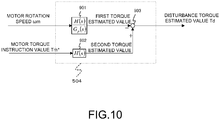
- the following describes a configuration of a disturbance torque estimator 504 illustrated in FIG. 6 with reference to FIG. 10 .
- FIG. 10 is a block diagram illustrating details of the disturbance torque estimator 504 and to calculate the disturbance torque estimated value Td based on the motor rotation speed ⁇ m and the motor torque command value Tm*.
- the disturbance torque estimator 504 calculates the disturbance torque estimated value Td based on the detected motor rotation speed ⁇ m and the motor torque command value Tm*.
- a control block 901 functions as a filter having a transmission characteristic H(s)/Gp(s) and inputs the motor rotation speed ⁇ m and performs the filtering process, thus calculating a first motor torque estimated value.
- Gp(s) is a vehicle model for the transmission characteristic of the torque input to the vehicle and the rotation speed of the motor.
- H(s) is a low-pass filter having such a transmission characteristic that a difference between the denominator degree and the numerator degree is equal to or more than a difference between the denominator degree and the numerator degree of a model Gr(s).
- a control block 902 functions as a low-pass filter having a transmission characteristic H(s) and inputs the motor torque command value Tm* and performs the filtering process, thus calculating a second motor torque estimated value.
- the resistances unrelated to the gradient such as the braking amount of the brake, an air resistance, a rolling resistance, and a turning resistance may be considered.
- a subtractor 903 calculates the disturbance torque estimated value Td by subtracting the first motor torque estimated value from the second motor torque estimated value.
- the disturbance torque according the embodiment is estimated by a disturbance observer as illustrated in FIG. 10 , it may be estimated using a meter such as a vehicle longitudinal G sensor.
- the disturbance torque estimator 504 calculates the disturbance torque estimated value Td based on the motor torque command value Tm*, the motor rotation speed ⁇ m, and the vehicle model Gp(s). This achieves a smooth vehicle stop from deceleration under any driving condition.
- the motor torque command value Tm* may be converged to 0, eliminating the need for the calculation of the disturbance torque estimated value Td.
- An adder 505 adds the F/B torque calculated by the F/B torque setting device 502 and the F/F torque calculated by the F/F torque setting device 503 to calculate a motor rotation speed F/B torque T ⁇ .
- An adder 506 adds the motor rotation speed F/B torque T ⁇ calculated by the adder 505 and the disturbance torque estimated value Td calculated by the disturbance torque estimator 504 to calculate the second torque target value Tm2*.
- a just-before-stop determining torque setting device 507 calculates a just-before-stop determining torque based on the detected motor rotation speed ⁇ m and the disturbance torque estimated value Td.
- FIG. 11 is a block diagram describing a method for calculating the just-before-stop determining torque based on the motor rotation speed ⁇ m.
- the just-before-stop determining torque setting device 507 includes a multiplier 1001.
- the just-before-stop determining torque setting device 507 adds the disturbance torque estimated value Td to a value obtained by multiplying the motor rotation speed ⁇ m by the total gain Kvref to calculate the just-before-stop determining torque.
- the just-before-stop determining torque becomes larger than the first torque target value Tm1*.
- the torque comparator 508 determines that the vehicle is just before stop of the vehicle and switches the motor torque command value Tm* from the first torque target value Tm1* to the second torque target value Tm2*.
- the torque comparator 508 determines that the just-before-stop determining torque is equal to or smaller than the first torque target value Tm1*, the torque comparator 508 determines that the vehicle is prior to just before the stop of the vehicle and sets the first torque target value Tm1* to the motor torque command value Tm*. Meanwhile, when the torque comparator 508 determines that the just-before-stop determining torque is larger than the first torque target value Tm1*, the torque comparator 508 determines that the vehicle is just before the stop of the vehicle and switches the motor torque command value Tm* from the first torque target value Tm1* to the second torque target value Tm2*.
- the second torque target value Tm2* converges to the positive torque on the uphill road, the negative torque on the downhill road, and almost 0 on the flat road.
- FIG. 13 are diagrams illustrating examples of the control results by the control device for electric motor vehicle according to the embodiment.
- FIG. 13 illustrates the control results when the vehicle stops on the flat road.
- FIG. 13 shows the braking amount of the brake, the motor rotation speed, the motor torque command value, and a vehicle longitudinal acceleration in the order from the above.
- the dotted line in the diagram expressing the motor rotation speed shows the corrected motor rotation speed estimated value and the dotted line in the diagram expressing the motor torque command value shows the disturbance torque estimated value.
- the electric motor 4 is decelerated based on the first torque target value Tm1* calculated in Step S202 in FIG. 2 .
- the disturbance torque estimated value is 0; therefore, it is seen that the vehicle travels on the flat road.
- the braking amount B of the brake increases.
- the use of the first torque target value Tm1* and the braking amount B of the brake in combination increases the vehicle longitudinal acceleration in the negative direction, namely, the braking side.
- the torque comparator 508 determines that the just-before-stop determining torque is larger than the first torque target value Tm1*, the torque comparator 508 determines that the vehicle is just before the stop of the vehicle and switches the first torque target value Tm1* calculated in Step S202 to the second torque target value Tm2* calculated in Step S203 for deceleration.
- the correction is made considering the braking amount B of the brake. Therefore, it is seen that the motor rotation speed matches the corrected motor rotation speed estimated value.
- the simple vehicle model Gp"(s) constituting the motor rotation speed estimator 604 in FIG. 7 is initialized by the motor rotation speed ⁇ m to be set as an initial value of the motor rotation speed estimated value output from the F/F compensator 501.
- the following describes the control results in the case where the braking amount B of the brake is not considered to calculate the motor rotation speed estimated value by the F/F compensator 501 as a comparative example with reference to FIG. 14 .
- the electric motor 4 is decelerated based on the first torque target value Tm1* calculated in Step S202 in FIG. 2 .
- the disturbance torque estimated value is 0; therefore, it is seen that the vehicle travels on the flat road.
- the braking amount B of the brake increases.
- the use of the first torque target value Tm1* and the braking amount B of the brake in combination increases the vehicle longitudinal acceleration in the negative direction, namely, the braking side.
- the torque comparator 508 determines that the just-before-stop determining torque is larger than the first torque target value Tm1*, the torque comparator 508 determines that the vehicle is just before the stop of the vehicle and switches the first torque target value Tm1* calculated in Step S202 to the second torque target value Tm2* calculated in Step S203 for deceleration.
- the braking amount B of the brake is not considered. Therefore, it is seen that the motor rotation speed deviates from the motor rotation speed estimated value.
- the simple vehicle model Gp"(s) constituting the motor rotation speed estimator 604 in FIG. 7 is initialized by the motor rotation speed ⁇ m to be set as an initial value of the motor rotation speed estimated value output from the F/F compensator 501.
- the motor rotation speed indicates the negative value. It is seen that that the vehicle retreats and fails to smoothly stop. This occurs because the braking force of the vehicle by the braking amount of the brake is lost due to the release of the braking amount of the brake.
- the control device for electric motor vehicle uses the motor as the traveling driving source.
- the control device for electric motor vehicle is configured to decelerate by the regenerative braking force from the motor.
- the control device for electric motor vehicle is configured to detect the amount of the accelerator operation, detect the motor rotation speed proportionate to the traveling speed of the electric motor vehicle, and calculate the motor rotation speed estimated value according to the state of the electric motor vehicle. Additionally, the control device for electric motor vehicle is configured to detect or estimate the resistance component unrelated to the gradient from the vehicle state and correct the motor rotation speed estimated value according to the resistance component.
- control device for electric motor vehicle is configured to calculate the feedback torque to stop the electric motor vehicle based on the motor rotation speed and calculate the feedforward torque to compensate the feedback torque based on the corrected motor rotation speed estimated value.
- the control device for electric motor vehicle is configured to calculate the motor torque command value and control the motor based on the calculated motor torque command value.
- the amount of accelerator operation is equal to or less than the predetermined value intends the amount of accelerator operation when the vehicle sufficiently travels at a low speed (for example, a speed of 15 km/h or less) without an intervention of a braking device separate from the regeneration braking.
- a low speed for example, a speed of 15 km/h or less
- the exemplary vehicle speed is one example.
- the detected motor rotation speed is multiplied by the predetermined gain K1 to distribute the regenerative braking force from the motor to calculate the feedback torque.
- the corrected motor rotation speed is multiplied by the specific gain K2 set according to the predetermined gain K1 to calculate the feedforward torque.
- the feedback torque obtained by adding the feedforward torque calculated by the multiplication of K2 to the feedback torque calculated by the multiplication of K1 is set as the motor torque command value. This appropriately distributes the feedforward torque and the feedback torque, thereby ensuring smoothly stopping the electric motor vehicle while the extension of the braking distance is reduced.
- the resistance component unrelated to the gradient is the braking amount of the brake that applies the braking force to the vehicle.
- the motor rotation speed correction value is calculated from the braking amount of the brake to correct the motor rotation speed estimated value based on the calculated motor rotation speed correction value. Accordingly, in the case where the braking force is applied to the vehicle except for the regenerative braking by the motor, the motor torque can also be converged to 0 together with the reduction in motor rotation speed. Therefore, even if the braking amount of the brake is input to the vehicle, the vehicle can smoothly stop and the vehicle stop state can be held.
- the amount of brake operation by the driver can be detected, and the braking amount of the brake is decided based on the detected amount of brake operation.
- This allows the correction of the motor rotation speed estimated value based on the sensor value detected by a brake fluid pressure sensor, a brake pedal stroke sensor, or a similar device, thereby ensuring the correction based on the actual measured value of the vehicle.
- the braking amount of the brake may be decided based on the command value regarding the brake operation (such as an braking amount of the brake command value). This ensures deciding the disturbance torque estimated value without a dead time such as a sensor detection delay.
- the braking amount of the brake is decided considering the responsiveness from when the braking amount of the brake is input to the vehicle until the braking force acts on the vehicle. Accordingly, the braking amount of the brake considers the responsiveness such as a response from the braking amount of the brake command value until the start of the brake fluid pressure and a response from the start of the brake fluid pressure until the action of the braking force to the vehicle, thereby ensuring restraining a model error between the vehicle model and the actual vehicle.
- the mark for the motor rotation speed correction value differs depending on the traveling direction of the vehicle. Accordingly, according to the vehicle longitudinal speed (including the speed parameters of the vehicle such as a vehicle body speed, a wheel speed, the motor rotation speed, and a drive shaft rotation speed), the mark for the braking amount of the brake is inverted and the motor rotation speed correction value is calculated. This allows appropriately correcting the motor rotation speed both in the forward movement and the backward movement of the vehicle.
- the motor rotation speed correction value is calculated using the filter including the model Gb(s) for the transmission characteristic of the input of the braking amount of the brake to the vehicle and the rotation speed of the motor. This allows accurately canceling the braking amount of the brake from the motor rotation speed correction value.
- releasing the braking amount of the brake initializes the motor rotation speed estimated value by the motor rotation speed. This allows cancelling the error occurred in the braking of the brake.
- the first embodiment estimates the disturbance torque, and when the amount of accelerator operation is equal to or less than the predetermined value and the electric motor vehicle is just before the stop of the vehicle, the motor torque command value Tm* is converged to the disturbance torque estimated value Td together with the reduction in the motor rotation speed. Therefore, regardless of the uphill road, the flat road, and the downhill road, this embodiment achieves the smooth deceleration without the acceleration vibration in the longitudinal direction just before the stop of the vehicle and ensures holding the vehicle stop state.
- a control device for electric motor vehicle of the second embodiment uses a vibration damping control together in addition to the above-described first embodiment.
- the following describes the control device for electric motor vehicle in this embodiment, especially aspects of the combination use of the vibration damping control.
- FIG. 15 is a control flowchart for the motor control of the control device for electric motor vehicle of the second embodiment.
- the vibration damping control process is performed in Step S203a.
- Step S203a the process in Step S203a is performed after Step S203 (stop control process).
- This embodiment sets the motor torque command value Tm* calculated in Step S203 in the above-described first embodiment, that is, the motor torque command value Tm* (see FIG. 6 ), which is the output from the torque comparator 508, as a third torque target value Tm3* (see FIG. 16 ).
- the motor torque command value Tm* is obtained.
- Step S203a the motor torque command value Tm3* calculated in Step S203 and the motor rotation speed ⁇ m are input to a vibration damping control block 1701 (see FIG. 17 ).
- the vibration damping control block 1701 calculates the motor torque command value Tm* after the vibration damping control, which reduces a torque transmission system vibration (such as a torsional vibration of the drive shaft).
- a torque transmission system vibration such as a torsional vibration of the drive shaft.
- FIG. 18 is a block diagram of the vibration damping control process used in this embodiment.
- a feedforward compensator 1801 (hereinafter referred to as an F/F compensator) functions as a filter having a transmission characteristic Gr(s)/Gp(s), which is constituted of the transmission characteristic Gr(s) and an inverse system as the model Gp(s) for the transmission characteristic of the torque input to the vehicle and the rotation speed of the motor.
- the used transmission characteristic Gr(s) can be expressed by the following Equation (14). [Equation 14]
- Gr s Mp ⁇ s 2 + 2 ⁇ z ⁇ ⁇ z ⁇ s + ⁇ z 2 / s s 2 + 2 ⁇ p ⁇ s + ⁇ p 2
- the vibration damping control performed by the F/F compensator 1801 may be the vibration damping control described in JP2001-45613A or may be the vibration damping control described in JP2002-152916A .
- Control blocks 1803 and 1804 are filters used for the feedback control (hereinafter the feedback is referred to as the F/B).
- the control block 1803 is the filter having the above-described transmission characteristic Gp(s).
- the control block 1803 inputs a value obtained by adding the output from the F/F compensator 1801 to the output from the control block 1804 described later, which is output from an adder 1805, and performs the filtering process.
- a subtractor 1806 subtracts the motor rotation speed ⁇ m from the value output from the control block 1803. The subtracted value is input to the control block 1804.
- the control block 1804 is a filter having a transmission characteristic H(s)/Gp(s), which is constituted of the low-pass filter H(s) and an inverse system of the model Gp(s) for the transmission characteristic of the torque input to the vehicle and the rotation speed of the motor.
- the control block 1804 inputs the output from the subtractor 1806, performs the filtering process, and outputs the value calculated as an F/B compensation torque to the adder 1805.
- the adder 1805 adds the third torque target value Tm3* on which the vibration damping control process has been performed by the F/F compensation to the above-described value calculated as the F/B compensation to calculate the motor torque command value Tm* to reduce the vibrations in the torque transmission system for the vehicle.
- the vibration damping control performed by the vibration damping control block 1701 may be the vibration damping control described in JP2003-9566A or may be the vibration damping control described in JP2010-288332A .
- the vehicle model Gp(s) expressed by Equation (6) in the first embodiment can be regarded as the transmission characteristic Gr(s) indicated in Equation (14).
- the filter having the transmission characteristic H(s)/Gp(s) which is shown in the control block 901 in FIG. 10 , can be regarded as the filter having the transmission characteristic H (s)/Gr(s) as illustrated in a control block 1901 in FIG. 19 .
- FIG. 20 is a block diagram describing the calculation of the brake torque estimated value in combination use of the vibration damping control.
- a control block 2001 sets a past value of the motor rotation speed estimated value considering the dead time. It should be noted that, the dead time here is, for example, the sensor detection delay of the vehicle.
- a control block 2002 performs a vibration damping control (F/B compensator) process G FB (s) according to the past value of the motor rotation speed correction value set by the control block 2001 to calculate a vibration damping control torque estimated value T F/B .
- FIG. 21 is a diagram describing the details of the vibration damping control (F/B compensator) process G FB (s) performed by the control block 2002.
- a control block 2101 is a filter having a transmission characteristic H(s)/Gp(s).
- Gp(s) is the model for the transmission characteristic of the torque input to the vehicle and the rotation speed of the motor.
- H(s) is a low-pass filter having such a transmission characteristic that a difference between the denominator degree and the numerator degree is equal to or more than a difference between the denominator degree and the numerator degree of a model Gp(s).
- a control block 2102 is a filter having the transmission characteristic Gp(s) and outputs a value obtained by inputting the output from the control block 2101 and performing the filtering process on the input value to a subtractor 2100.
- the subtractor 2100 subtracts the past value of the motor rotation speed correction value from the value output from the control block 2102 to output the obtained value through the subtraction to the control block 2101. Accordingly, the vibration damping control torque estimated value T F/B on which the vibration damping control (F/B compensator) process has been performed can be calculated from the motor rotation speed correction value.
- the vibration damping control may be the vibration damping control described in JP2003-9566A or may be the vibration damping control described in JP2010-288332A .
- a control block 2003 performs the process of the transmission characteristic Gb(s) indicated in Equation (12) according to the braking amount B of the brake, the vibration damping control torque command value T F/B , and the wheel speed ⁇ m to calculate the motor rotation speed correction value after the vibration damping control.
- the adder 602 illustrated in FIG. 7 adds the motor rotation speed correction value after the vibration damping control to the motor rotation speed estimated value to correct the motor rotation speed estimated value.
- the second embodiment calculates the motor rotation speed correction value using the model of the transmission characteristic considering the vibration damping control. This allows accurately canceling the braking amount of the brake from the motor rotation speed estimated value also in the case where the vibration damping control is used.
- the present invention is not limited to the above-described one embodiment but various modifications and applications are possible.
- the above-described explanation describes that, when the amount of accelerator operation is equal to or less than the predetermined value and the electric motor vehicle is just before the stop of the vehicle, the motor torque command value Tm* is converged to the disturbance torque estimated value Td (or 0) together with the reduction in the rotation speed of the electric motor 4.
- the speed parameters such as the wheel speed, the vehicle body speed, and the rotation speed of the drive shaft are proportional relationship with the rotation speed of the electric motor 4. Accordingly, the motor torque command value Tm* may be converged to the disturbance torque estimated value Td (or 0) together with the reduction in speed parameter, which is proportionate to the rotation speed of the electric motor 4.
Landscapes
- Engineering & Computer Science (AREA)
- Power Engineering (AREA)
- Transportation (AREA)
- Mechanical Engineering (AREA)
- Electric Propulsion And Braking For Vehicles (AREA)
- Control Of Motors That Do Not Use Commutators (AREA)
- Hybrid Electric Vehicles (AREA)
Abstract
Description
- The present invention relates to a control device for electric motor vehicle and a control method for electric motor vehicle.
- Conventionally, a regenerative brake control device for electric vehicles provided with setting means capable of any given setting of a regenerative braking force of a motor and regenerates the motor by a regenerative braking force set by the setting means is known (see
JP8-79907A - However, the technique in
JP8-79907A - An object of the present invention is to provide a technique that reduces the generation of vibration in a longitudinal direction of a vehicle body in stopping an electric motor vehicle with a regenerative braking force.
- A device for controlling an electric vehicle according to an embodiment is that a control device for electric motor vehicle uses the motor as the traveling driving source. The control device for electric motor vehicle is configured to decelerate by the regenerative braking force from the motor. The control device for electric motor vehicle is configured to detect the amount of the accelerator operation, detect the motor rotation speed proportionate to the traveling speed of the electric motor vehicle, and calculate the motor rotation speed estimated value according to the state of the electric motor vehicle. Additionally, the control device for electric motor vehicle is configured to detect or estimate the resistance component unrelated to the gradient from the vehicle state and correct the motor rotation speed estimated value according to the resistance component. Further, the control device for electric motor vehicle is configured to calculate the feedback torque to stop the electric motor vehicle based on the motor rotation speed and calculate the feedforward torque to compensate the feedback torque based on the corrected motor rotation speed estimated value. The control device for electric motor vehicle is configured to calculate the motor torque command value and control the motor based on the calculated motor torque command value. When the amount of the accelerator operation is equal to or less than the predetermined value and the electric motor vehicle is just before the stop of the vehicle, the motor torque command value is converged to 0 based on the feedback torque and the feedforward torque together with the reduction in the traveling speed.
- Embodiments of the present invention and merits of the present invention will be described below in detail together with the attached drawings.
-
-
FIG. 1 is a block diagram illustrating a main configuration of an electric vehicle with a control device for electric motor vehicle according to a first embodiment. -
FIG. 2 is a flow of processes for a motor current control performed by a motor controller provided with the control device for electric motor vehicle of the first embodiment. -
FIG. 3 is a diagram illustrating an example of an accelerator position (accelerator opening degree)-torque table. -
FIG. 4 is a diagram modeling a drive force transmission system of the vehicle. -
FIG. 5 is a diagram modeling the drive force transmission system of the vehicle. -
FIG. 6 is a block diagram for achieving a stop control process. -
FIG. 7 is a block diagram describing a method for calculating a motor rotation speed estimated value by a feedforward compensator (addition of a response adjusting filter). -
FIG. 8 is a diagram describing a method for calculating an F/B torque based on a motor rotation speed. -
FIG. 9 is a diagram describing a method for calculating an F/F torque based on the motor rotation speed estimated value. -
FIG. 10 is a diagram describing a method for calculating a disturbance torque estimated value. -
FIG. 11 is a diagram describing a method for calculating a just-before-stop determining torque based on a motor rotation speed and the disturbance torque estimated value. -
FIG. 12 is a diagram describing a method for calculating a motor rotation speed correction value in the control device for electric motor vehicle of the first embodiment. -
FIG. 13 are diagrams illustrating examples of control results by the control device for electric motor vehicle of the first embodiment. -
FIG. 14 are diagrams illustrating examples of control results of a comparative example. -
FIG. 15 is a flow of processes for a motor current control performed by a motor controller provided with a control device for electric motor vehicle of a second embodiment. -
FIG. 16 is a block diagram of a stop control process in the control device for electric motor vehicle of the second embodiment. -
FIG. 17 is a block diagram of a vibration damping control process in the control device for electric motor vehicle of the second embodiment. -
FIG. 18 is a block diagram expressing details of the vibration damping control process in the control device for electric motor vehicle of the second embodiment. -
FIG. 19 is a diagram describing a method for calculating the disturbance torque estimated value in the control device for electric motor vehicle of the second embodiment. -
FIG. 20 is a diagram describing a method for calculating the motor rotation speed correction value in the control device for electric motor vehicle of the second embodiment. -
FIG. 21 is a diagram describing a method for calculating a vibration damping control torque estimated value in the control device for electric motor vehicle of the second embodiment. -
FIG. 1 is a block diagram illustrating a main configuration of an electric vehicle with a control device for electric motor vehicle of the first embodiment. The control device for electric motor vehicle of the present invention includes anelectric motor 4 as part or the entirety of a drive source of the vehicle and is applicable to an electric motor vehicle capable of traveling by a drive force of the electric motor. Electric motor vehicles include not only electric vehicles, but also hybrid vehicles and fuel cell vehicles. Particularly, the control device for electric motor vehicle according to the embodiment can be applied to a vehicle capable of controlling acceleration/deceleration and a stop of the vehicle only by an operation of an accelerator pedal. In this vehicle, a driver depresses the accelerator pedal during acceleration and reduces or zeros an amount of depression of the depressed accelerator pedal during deceleration or during stop. It should be noted that, the vehicle approaches the stop state while the driver depresses the accelerator pedal to prevent the vehicle from retreating on uphill roads in some cases. - A
motor controller 2 has signals indicating vehicle states such as a vehicle speed V, an accelerator position AP, a rotator phase α of the electric motor (three-phase alternating current motor) 4 and currents iu, iv, and iw of theelectric motor 4, which are input to themotor controller 2 in the form of digital signals, and generates PWM signals for controlling theelectric motor 4 based on the input signals. Themotor controller 2 performs an open/close control of a switching element of aninverter 3 by the generated PWM signal. Themotor controller 2 has functions as motor rotation speed estimating means, motor rotation speed estimated value correction means, feedback torque calculating means, feedforward torque calculating means, motor torque command value calculation means, motor control means, and disturbance torque estimating means. The motor rotation speed estimating means calculates a motor rotation speed estimated value, which will be described later. The motor rotation speed estimated value correction means corrects a motor rotation speed estimated value based on an amount of braking of a brake, which will be described later. The feedback torque calculating means calculates a feedback torque, which will be described later. The feedforward torque calculating means calculates a feedforward torque, which will be described later. The motor torque command value calculation means calculates a motor torque command value, which will be described later. The motor control means controls theelectric motor 4 based on the motor torque command value. The disturbance torque estimating means estimates a disturbance torque, which will be described later. - The
inverter 3 turns on/off, for example, two switching elements (for example, power semiconductor elements such as IGBTs and MOS-FETs) for each phase to convert a direct current supplied from abattery 1 into an alternating current and causes a desired current to flow into theelectric motor 4. - The
electric motor 4 generates a drive force by the alternating current supplied from theinverter 3 and transmits the drive force to right andleft drive wheels speed reducer 5 and adrive shaft 8. Further, when being rotated following the rotation of thedrive wheels electric motor 4 generates a regenerative drive force, thereby collecting the kinetic energy of the vehicle as electrical energy. In this case, theinverter 3 converts an alternating current generated during the regenerative operation of theelectric motor 4 into a direct current and supplies the direct current to thebattery 1. - A
current sensor 7 detects the three-phase alternating currents iu, iv and iw flowing in theelectric motor 4. Note that, since the sum of the three-phase alternating currents iu, iv and iw is 0, the currents of any of two phases may be detected and the current of the remaining one phase may be obtained by calculation. - A
rotation sensor 6 functions as vehicle speed detecting means to detect a motor rotation speed as a speed parameter. Therotation sensor 6 is, for example, a resolver or an encoder and detects the rotator phase α of theelectric motor 4. - A brake controller 11 sets an braking amount B of the brake according to the amount of depression of a
brake pedal 10 to control a brake fluid pressure according to the braking amount B of the brake. - A
fluid pressure sensor 12 detects the brake fluid pressure to obtain the braking amount B of the brake and outputs the obtained braking amount B of the brake to themotor controller 2. That is, thefluid pressure sensor 12 functions as means to detect the braking amount of the brake as a resistance component unrelated to a gradient. - A
friction brake 13 starts the brake fluid pressure according to the braking amount B of the brake to press a brake pad to a rotor, thus generating a braking force in the vehicle. -
FIG. 2 is a flowchart showing a flow of processes for a motor current control performed by themotor controller 2. - In Step S201, signals indicating the vehicle states are input. Here, the vehicle speed V (km/h), the accelerator position AP (%), the rotator phase α (rad) of the
electric motor 4, a rotation speed Nm (rpm) of theelectric motor 4, the three-phase alternating currents iu, iv and iw flowing in theelectric motor 4, a direct-current voltage value Vdc (V) between thebattery 1 and theinverter 3, and the braking amount B of the brake are input. - The vehicle speed V (km/h) is obtained by a vehicle speed sensor (not illustrated) or through communications from another controller. Alternatively, the vehicle speed v (m/s) is obtained by multiplying a rotator mechanical angular velocity ωm by a tire dynamic radius R and dividing the product by a gear ratio of a final gear, and then multiplied by 3600/1000 for unit conversion, thereby obtaining the vehicle speed V (km/h).
- The accelerator position AP (%) is obtained from an accelerator position (not illustrated) or through communications from another controller such as a vehicle controller (not illustrated).
- The rotator phase α (rad) of the
electric motor 4 is obtained from therotation sensor 6. The rotation speed Nm (rpm) of theelectric motor 4 is obtained by dividing a rotator angular velocity ω (electric angle) by a pole pair number p of theelectric motor 4 to obtain a motor rotation speed ωm (rad/ s) (speed parameter), which is a mechanical angular velocity of theelectric motor 4, and multiplying the obtained motor rotation speed ωm by 60/ (2π). The rotator angular velocity ω is obtained by differentiating the rotator phase α. - The currents iu, iv and iw (A) flowing in the
electric motor 4 are obtained from thecurrent sensor 7. - The direct-current voltage value Vdc (V) is obtained from a voltage sensor (not illustrated) provided in a direct-current power supply line between the
battery 1 and theinverter 3 or a power supply voltage value transmitted from a battery controller (not illustrated). - The braking amount B of the brake is obtained from the
fluid pressure sensor 12, which detects the brake fluid pressure. A value of, for example, a stroke sensor (not illustrated), which detects an amount of brake operation by the driver, may be used. Alternatively, a brake command value may be obtained from the vehicle controller (not illustrated) and another controller through communications to set the brake command value as the braking amount B of the brake. It should be noted that, when the braking amount B of the brake is set from the sensor value or the command value, responsiveness from when the braking amount B of the brake is input to the vehicle until the braking force actually acts on the vehicle is taken into consideration. - In Step S202, a first torque target value Tm1* is set. Specifically, the first torque target value Tm1* is set based on the accelerator position AP and the motor rotation speed ωm input in Step S201 by referring to an accelerator position-torque table illustrated in
FIG. 3 . As described above, the control device for electric motor vehicle according to the embodiment can be applied to the vehicle capable of controlling acceleration/deceleration and the stop of the vehicle only by the operation of the accelerator pedal. To at least ensure stopping the vehicle by full closing of the accelerator pedal, in the accelerator position-torque table illustrated inFIG. 3 , a motor torque is set such that an amount of motor regeneration with the accelerator position of 0 (fully closed) increases. That is, when the motor rotation speed is positive and at least the accelerator position is 0 (fully closed), the negative motor torque is set so as to work the regenerative braking force. Note that, the accelerator position-torque table is not limited to the table illustrated inFIG. 3 . - In Step S203, a stop control process is performed. Specifically, whether the electric motor vehicle is just before the stop of the vehicle is determined. The first torque target value Tm1* calculated in Step S202 is set as a motor torque command value Tm* before the electric motor vehicle is just before the stop of the vehicle, and a second torque target value Tm2*, which converges to a disturbance torque command value Td, with a reduction in the motor rotation speed is set as the motor torque command value Tm* after the electric motor vehicle is just before the stop of the vehicle. This second torque target value Tm2* is a positive torque on an uphill road, a negative torque on a downhill road and almost 0 on a flat road. In this way, the vehicle stop state can be maintained regardless of a gradient of a road surface as described later. The detail of the stop control process is described later.
- In Step S204, a d-axis current target value id* and a q-axis current target value iq* are obtained based on the motor torque target value Tm* calculated in Step S203, the motor rotation speed ωm, and the direct-current voltage value Vdc. For example, a table obtaining a relationship of the d-axis current target value and the q-axis current target value with the torque command value, the motor rotation speed, and the direct-current voltage value is prepared in advance and the d-axis current target value id* and the q-axis current target value iq* are obtained by referring to this table.
- In Step S205, a current control is performed to match a d-axis current id and a q-axis current iq with the d-axis current target value id* and the q-axis current target value iq* obtained in Step S204, respectively. To this end, the d-axis current id and the q-axis current iq are first obtained based on the three-phase alternating current values iu, iv and iw and the rotator phase α of the
electric motor 4 input in Step S201. Subsequently, d-axis and q-axis voltage command values vd and vq are calculated from deviations between the d-axis and q-axis current command values id*, iq* and the d-axis and q-axis currents id and iq. It should be noted that a non-interference voltage necessary to cancel out an interference voltage between d-q orthogonal coordinate axes may be added to the calculated d-axis and q-axis voltage command values vd and vq. - Subsequently, from the d-axis and q-axis voltage command values vd and vq and the rotator phase α of the
electric motor 4 and from three-phase alternating-current voltage command values vu, w, and vw and the current voltage value Vdc, PWM signals tu (%), tv (%), and tw (%) are obtained. By opening and closing the switching elements of theinverter 3 by the PWM signals tu, tv and tw obtained in this way, theelectric motor 4 can be driven with a desired torque instructed by the torque command value Tm*. - Here, before the stop control process performed in Step S203 is described, a transmission characteristic Gp(s) from the motor torque Tm to the motor rotation speed ωm is described in the control device for electric motor vehicle according to the embodiment.
-
FIG. 4 andFIG. 5 are diagrams modeling a drive force transmission system of the vehicle, and respective parameters in the diagrams are as described below. - Jm: inertia of electric motor
- Jw: inertia of drive wheels
- M: weight of vehicle
- KD: torsional rigidity of drive system
- Kt: coefficient relating friction between tires and road surface
- N: overall gear ratio
- r : excessive radius of tires
- ωm: angular velocity of electric motor
- Tm: torque target value Tm*
- TD: torque of drive wheels
- F: force applied to vehicle
- V: speed of vehicle
- ωw: angular velocity of drive wheels
- The following equations of motion can be derived from
FIG. 4 andFIG. 5 . Note that, the asterisk (*) attached to the right-upper corner of a symbol in the following Equations (1) to (3) indicates a time differential.
[Equation 1]
[Equation 2]
[Equation 3]
[Equation 4]
[Equation 5]
- The transmission characteristic Gp(s) from the torque target value Tm of the
electric motor 4 to the motor rotation speed ωm obtained based on the equations of motion (1) to (5) is expressed by the following Equation (6).
[Equation 6]
- Here, each parameter in Equation (6) is expressed by the following Equation (7).
[Equation 7]
- Through examinations, the poles and 0 point of a transfer function shown in Equation (6) can be approximated to a transfer function of the following Equation (8), and one pole and one 0 point indicate values extremely close to each other. This is equivalent to that α and β of the following Equation (8) indicate values extremely close to each other.
[Equation 8]
- Accordingly, by performing pole-zero cancellation (approximation to α = β) in Equation (8), Gp(s) constitutes a transmission characteristic of (second order) / (third order) as shown in the following Equation (9).
[Equation 9]
- For reduction in operation amount, simplifying a transmission characteristic Gp'(s) can obtain the following Equation (10).
[Equation 10]
- The following describes the transmission characteristic Gp(s) from the braking amount B of the brake to the motor rotation speed ωm,
- The braking amount B of the brake is the braking force applied to the vehicle. The equation of motion expressed by the following Equation (11) can be derived from
FIG. 4 andFIG. 5 .
[Equation 11]
- Note that, the braking amount B of the brake in Equation (11) is as follows.


- To obtain the transmission characteristic Gb(s) from the braking amount B of the brake to the motor rotation speed ωm based on the equations of motion indicated by the Equations (1), (3), (4), (5), and (11), the transmission characteristic Gb(s) is expressed by the following Equation (12).
[Equation 12]
- Note that, the parameters in Equation (12) are expressed by the following Equation (13).
[Equation 13]
- Next, the detail of the stop control process performed in Step S203 of
FIG. 2 is described.FIG. 6 is a block diagram for achieving the stop control process. - A feedforward compensator (hereinafter referred to as an F/F compensator) 501 calculates a motor rotation speed estimated value based on the obtained braking amount B of the brake. The following describes details of the F/
F compensator 501 with reference toFIG. 7 andFIG. 12 . -
FIG. 7 is a diagram describing a method for calculating the motor rotation speed estimated value according to the state of the electric motor vehicle. Abrake torque estimator 601 calculates a motor rotation speed correction value to correct the motor rotation speed estimated value based on the braking amount B of the brake.FIG. 12 illustrates details of thebrake torque estimator 601. -
FIG. 12 is a diagram describing a method for calculating the motor rotation speed correction value according to the braking amount B of the brake. Acontrol block 1201 performs a process of the transmission characteristic Gb(s) expressed by the above-described Equation (12) on the braking amount B of the brake to calculate the motor rotation speed correction value. The braking force by the brake acts in a direction that the motor rotation converges to 0 rpm both in forward movement and backward movement. Accordingly, the motor rotation speed correction value is calculated such that the motor rotation acts in the direction of converging to 0 rpm according to a sign of a vehicle longitudinal speed. The sign of the motor rotation speed correction value in the embodiment is negative during the forward movement of the vehicle and positive during the backward movement of the vehicle. The motor rotation speed correction value is output to anadder 602 illustrated inFIG. 7 . - Referring back to
FIG. 7 , the explanation will be continued. Theadder 602 adds the motor rotation speed correction value calculated by thebrake torque estimator 601 to the motor rotation speed estimated value to correct the motor rotation speed estimated value. Theadder 602 outputs the corrected motor rotation speed estimated value to acontrol block 603. - A
motor torque estimator 603 multiplies the corrected motor rotation speed estimated value output from theadder 602 by a predetermined gain (hereinafter referred to as a total gain) Kvref (Kvref < 0) to calculate a motor torque estimated value. The total gain Kvref is a predetermined value to smoothly stop the electric motor vehicle while an extension of a braking distance is reduced, and is, for example, appropriately set by experimental data or similar data. - A motor
rotation speed estimator 604 converts the motor torque estimated value into the motor rotation speed estimated value based on the vehicle model Gp(s) indicated by Equation (6). This embodiment uses a vehicle simple model Gp"(s) indicated by Equation (10), instead of the vehicle model Gp(s). - The motor
rotation speed estimator 604 inputs the motor torque estimated value calculated by themotor torque estimator 603 to the vehicle simple model Gp"(s) to calculate the motor rotation speed estimated value based on the vehicle simple model Gp"(s). The motorrotation speed estimator 604 outputs the motor rotation speed estimated value based on the vehicle simple model Gp"(s) to theadder 602 and a low-pass filter 605. - In the case where a
torque comparator 508, which will be described later, determines that the electric motor vehicle is just before the stop of the vehicle and the case where the braking amount B of the brake is released, the motorrotation speed estimator 604 initializes the vehicle simple model Gp"(s) based on the current motor rotation speed ωm. For example, the vehicle simple model Gp"(s) is constituted of constants a1' and b0', which are uniquely decided by a design value of the vehicle, and an integrator. When the motorrotation speed estimator 604 determines that the electric motor vehicle is just before the stop of the vehicle, setting the initial value of the above-described integrator to the motor rotation speed ωm initializes the vehicle simple model Gp"(s). During the braking of the brake, due to a change in a friction coefficient (µ) of the brake pad or a similar cause, an error occurs in the command value and the sensor value; and the braking force actually acting on the vehicle. Accordingly, the above-described initialization cancels the error occurred during the braking of the brake. - The low-
pass filter 605 is a low-pass filter with a transmission characteristic Hc(s) configured to complement the vehicle simple model Gp"(s). Here, a filtering process of the transmission characteristic Hc(s) is performed on the motor rotation speed estimated value calculated by the motorrotation speed estimator 604 for response adjustment. The transmission characteristic Hc(s) is set based on, for example, a simulation or experimental data. Specifically, with the total gain Kvref smaller than 0, a time constant of the transmission characteristic Hc(s) is adjusted such that the convergence of the motor rotation speed ωm and the convergence of the motor rotation speed estimated value input to an F/Ftorque setting device 503 to be equivalent. - Thus, the low-pass filter process is performed on the motor rotation speed estimated value input to the F/F
torque setting device 503. This corrects a discrepancy of the response characteristic in association with the use of the vehicle simple model Gp"(s). - Referring back to
FIG. 6 , the explanation will be continued. A feedback torque setting device (hereinafter referred to as an F/B torque setting device) 502 illustrated inFIG. 6 calculates an F/B torque based on the detected motor rotation speed ωm. The following describes the details with reference toFIG. 8 . -
FIG. 8 is a diagram describing a method for calculating the F/B torque based on the motor rotation speed ωm. The F/Btorque setting device 502 includes amultiplier 701 to convert the motor rotation speed ωm into the F/B torque. - The
multiplier 701 includes atotal gain multiplier 710 and adistribution coefficient multiplier 720. Themultiplier 701 multiplies the motor rotation speed ωm by an F/B gain K1 (Kvref × β), which is determined to distribute the regenerative braking force by the electric motor, 4 to calculate the F/B torque. The F/B gain K1 is set in a direction of weakening the regenerative braking force compared with the total gain Kvref. That is, the F/B gain K1 is set to a value smaller than 0 and larger than the total gain Kvref. - The
total gain multiplier 710 multiplies the motor rotation speed ωm by the total gain Kvref to calculate an F/B total torque. - The
distribution coefficient multiplier 720 multiplies the F/B total torque by the distribution coefficient β to calculate the F/B torque. Note that, the distribution coefficient β is a value larger than "0" and smaller than "1." The distribution coefficient β is set based on, for example, a simulation or experimental data. - Thus, the
multiplier 701 uses the value obtained by multiplying the total gain Kvref by the distribution coefficient β as the F/B gain K1, ensuring the F/B torque small so as to decrease the regenerative braking force. The motor rotation speed ωm is multiplied by the F/B gain K1 to calculate the F/B torque; therefore, the F/B torque is set as a torque from which the large regenerative braking force is obtained with the larger motor rotation speed ωm. - The following describes a configuration of the F/F
torque setting device 503 illustrated inFIG. 6 . - The F/F
torque setting device 503 calculates the F/F torque based on the motor rotation speed estimated value calculated by the F/F compensator 501. The F/F torque supplements the insufficient regenerative braking force by the F/B torque just before the stop of the vehicle. -
FIG. 9 is a diagram describing a method for calculating the F/F torque based on the motor rotation speed estimated value. The F/Ftorque setting device 503 includes amultiplier 801 to convert the motor rotation speed estimated value into the F/F torque. - The
multiplier 801 multiplies the motor rotation speed estimated value by an F/ F gain K2 set according to the F/B gain K1 to calculate the F/F torque. Themultiplier 801 includes atotal gain multiplier 810 and adistribution coefficient multiplier 820. - The
total gain multiplier 810 multiplies the motor rotation speed estimated value by the total gain Kvref to calculate an F/F total torque. - The
distribution coefficient multiplier 820 multiplies the F/F total torque by the distribution coefficient (1 - β) to calculate the F/F torque. Note that, as described inFIG. 8 , since the distribution coefficient β is a value larger than "0" and is smaller than "1," the distribution coefficient (1 - β) is a value larger than "0" and smaller than "1." - Thus, the
multiplier 801 uses the value obtained by multiplying the total gain Kvref by the distribution coefficient (1 - β) as the F/F gain K2, ensuring assigning the amount of decreasing the F/B torque by the F/Btorque setting device 502 to the F/F torque. The motor rotation speed estimated value is multiplied by the F/F gain K2 to calculate the F/F torque; therefore, the F/F torque is set as a torque from which the large regenerative braking force is obtained with the larger motor rotation speed estimated value. - The following describes a configuration of a
disturbance torque estimator 504 illustrated inFIG. 6 with reference toFIG. 10 . -
FIG. 10 is a block diagram illustrating details of thedisturbance torque estimator 504 and to calculate the disturbance torque estimated value Td based on the motor rotation speed ωm and the motor torque command value Tm*. Thedisturbance torque estimator 504 calculates the disturbance torque estimated value Td based on the detected motor rotation speed ωm and the motor torque command value Tm*. - A
control block 901 functions as a filter having a transmission characteristic H(s)/Gp(s) and inputs the motor rotation speed ωm and performs the filtering process, thus calculating a first motor torque estimated value. Gp(s) is a vehicle model for the transmission characteristic of the torque input to the vehicle and the rotation speed of the motor. H(s) is a low-pass filter having such a transmission characteristic that a difference between the denominator degree and the numerator degree is equal to or more than a difference between the denominator degree and the numerator degree of a model Gr(s). - A
control block 902 functions as a low-pass filter having a transmission characteristic H(s) and inputs the motor torque command value Tm* and performs the filtering process, thus calculating a second motor torque estimated value. - It should be noted that, in the calculation of the second motor torque estimated value, the resistances unrelated to the gradient such as the braking amount of the brake, an air resistance, a rolling resistance, and a turning resistance may be considered.
- A
subtractor 903 calculates the disturbance torque estimated value Td by subtracting the first motor torque estimated value from the second motor torque estimated value. - It should be noted that although the disturbance torque according the embodiment is estimated by a disturbance observer as illustrated in
FIG. 10 , it may be estimated using a meter such as a vehicle longitudinal G sensor. - Here, while the air resistance, a modeling error caused by a variation of a vehicle weight due to the number of passengers and load capacity, a rolling resistance of the tires, a gradient resistance of the road surface, and a similar resistance are thought as the disturbances, a disturbance factor dominant just before the stop of the vehicle is the gradient resistance. While the disturbance factors differ depending on driving conditions, the disturbance factors described above can be collectively estimated since the
disturbance torque estimator 504 calculates the disturbance torque estimated value Td based on the motor torque command value Tm*, the motor rotation speed ωm, and the vehicle model Gp(s). This achieves a smooth vehicle stop from deceleration under any driving condition. Note that, as described above, since the disturbance torque on the flat road is almost 0, when the vehicle is just before the stop of the vehicle on the flat road, the motor torque command value Tm* may be converged to 0, eliminating the need for the calculation of the disturbance torque estimated value Td. - Returning to
FIG. 6 , the explanation will be continued. The following describes configurations other than the F/F compensator 501, the F/Btorque setting device 502, the F/Ftorque setting device 503, and thedisturbance torque estimator 504. - An
adder 505 adds the F/B torque calculated by the F/Btorque setting device 502 and the F/F torque calculated by the F/Ftorque setting device 503 to calculate a motor rotation speed F/B torque Tω. - An
adder 506 adds the motor rotation speed F/B torque Tω calculated by theadder 505 and the disturbance torque estimated value Td calculated by thedisturbance torque estimator 504 to calculate the second torque target value Tm2*. - A just-before-stop determining
torque setting device 507 calculates a just-before-stop determining torque based on the detected motor rotation speed ωm and the disturbance torque estimated value Td. - Here, the following describes the calculation of the just-before-stop determining torque with reference to
FIG. 11. FIG. 11 is a block diagram describing a method for calculating the just-before-stop determining torque based on the motor rotation speed ωm. The just-before-stop determiningtorque setting device 507 includes amultiplier 1001. The just-before-stop determiningtorque setting device 507 adds the disturbance torque estimated value Td to a value obtained by multiplying the motor rotation speed ωm by the total gain Kvref to calculate the just-before-stop determining torque. - Returning to
FIG. 6 , the following describes the configuration of thetorque comparator 508. - The
torque comparator 508 compares magnitudes between the first torque target value Tm1*, which is calculated in Step S202, and the just-before-stop determining torque, which is calculated by the just-before-stop determiningtorque setting device 507. - During the travelling of the vehicle, when the just-before-stop determining torque is smaller than the first torque target value Tm1*, and the vehicle decelerates and becomes just before the stop of the vehicle (the vehicle speed is equal to or less than a predetermined vehicle speed), the just-before-stop determining torque becomes larger than the first torque target value Tm1*. When the just-before-stop determining torque becomes larger than the first torque target value Tm1*, the
torque comparator 508 determines that the vehicle is just before stop of the vehicle and switches the motor torque command value Tm* from the first torque target value Tm1* to the second torque target value Tm2*. - Thus, when the
torque comparator 508 determines that the just-before-stop determining torque is equal to or smaller than the first torque target value Tm1*, thetorque comparator 508 determines that the vehicle is prior to just before the stop of the vehicle and sets the first torque target value Tm1* to the motor torque command value Tm*. Meanwhile, when thetorque comparator 508 determines that the just-before-stop determining torque is larger than the first torque target value Tm1*, thetorque comparator 508 determines that the vehicle is just before the stop of the vehicle and switches the motor torque command value Tm* from the first torque target value Tm1* to the second torque target value Tm2*. - It should be noted that, to maintain the vehicle stop state, the second torque target value Tm2* converges to the positive torque on the uphill road, the negative torque on the downhill road, and almost 0 on the flat road.
- The following describes effects when the control device for electric motor vehicle according to the embodiment is applied to the electric vehicle, especially describes a control during the braking of the brake with reference to
FIG. 13 andFIG. 14 . -
FIG. 13 are diagrams illustrating examples of the control results by the control device for electric motor vehicle according to the embodiment.FIG. 13 illustrates the control results when the vehicle stops on the flat road.FIG. 13 shows the braking amount of the brake, the motor rotation speed, the motor torque command value, and a vehicle longitudinal acceleration in the order from the above. The dotted line in the diagram expressing the motor rotation speed shows the corrected motor rotation speed estimated value and the dotted line in the diagram expressing the motor torque command value shows the disturbance torque estimated value. - At a time t0, the
electric motor 4 is decelerated based on the first torque target value Tm1* calculated in Step S202 inFIG. 2 . The disturbance torque estimated value is 0; therefore, it is seen that the vehicle travels on the flat road. - At a time t1, when the driver depresses the brake pedal, the braking amount B of the brake increases. At this time, it is seen that the use of the first torque target value Tm1* and the braking amount B of the brake in combination increases the vehicle longitudinal acceleration in the negative direction, namely, the braking side.
- From the time t1 to t2, when the
torque comparator 508 determines that the just-before-stop determining torque is larger than the first torque target value Tm1*, thetorque comparator 508 determines that the vehicle is just before the stop of the vehicle and switches the first torque target value Tm1* calculated in Step S202 to the second torque target value Tm2* calculated in Step S203 for deceleration. At this time, for the calculation of the motor rotation speed estimated value by the F/F compensator 501, the correction is made considering the braking amount B of the brake. Therefore, it is seen that the motor rotation speed matches the corrected motor rotation speed estimated value. - When the
torque comparator 508 determines that the vehicle is just before the stop of the vehicle, the simple vehicle model Gp"(s) constituting the motorrotation speed estimator 604 inFIG. 7 is initialized by the motor rotation speed ωm to be set as an initial value of the motor rotation speed estimated value output from the F/F compensator 501. - From the time t2 to t3, even if the braking amount B of the brake is released, the motor rotation speed, the motor torque command value, and the vehicle longitudinal speed are converged to 0. It can be seen that the vehicle can smoothly stop without involving the acceleration vibration in the longitudinal direction.
- Even at the time t3 and after the time t3, the motor rotation speed, the motor torque command value, and the vehicle longitudinal speed still converge to 0. It is seen that the vehicle stop state can be held.
- The following describes the control results in the case where the braking amount B of the brake is not considered to calculate the motor rotation speed estimated value by the F/
F compensator 501 as a comparative example with reference toFIG. 14 . - At a time t0, the
electric motor 4 is decelerated based on the first torque target value Tm1* calculated in Step S202 inFIG. 2 . The disturbance torque estimated value is 0; therefore, it is seen that the vehicle travels on the flat road. - At a time t1, when the driver depresses the brake pedal, the braking amount B of the brake increases. At this time, it is seen that the use of the first torque target value Tm1* and the braking amount B of the brake in combination increases the vehicle longitudinal acceleration in the negative direction, namely, the braking side.
- From the time t1 to t2, when the
torque comparator 508 determines that the just-before-stop determining torque is larger than the first torque target value Tm1*, thetorque comparator 508 determines that the vehicle is just before the stop of the vehicle and switches the first torque target value Tm1* calculated in Step S202 to the second torque target value Tm2* calculated in Step S203 for deceleration. At this time, for the calculation of the motor rotation speed estimated value by the F/F compensator 501, the braking amount B of the brake is not considered. Therefore, it is seen that the motor rotation speed deviates from the motor rotation speed estimated value. - When the
torque comparator 508 determines that the vehicle is just before the stop of the vehicle, the simple vehicle model Gp"(s) constituting the motorrotation speed estimator 604 inFIG. 7 is initialized by the motor rotation speed ωm to be set as an initial value of the motor rotation speed estimated value output from the F/F compensator 501. - From a time t2 to t3, the combination use of the second torque target value and the braking amount B of the brake once converges the vehicle longitudinal acceleration to 0 and the vehicle attempts to enter the vehicle stop state. However, it is seen that, when the braking amount of the brake is released, the vehicle longitudinal acceleration increases in the negative direction, namely, the retreat side, thus retreating the vehicle. This occurs because the
electric motor 4 is decelerated based on the second torque target value Tm2* calculated based on the motor rotation speed estimated value calculated without taking the braking amount B of the brake into consideration by the F/F compensator 501. - From a time t3 to t5, the motor rotation speed indicates the negative value. It is seen that that the vehicle retreats and fails to smoothly stop. This occurs because the braking force of the vehicle by the braking amount of the brake is lost due to the release of the braking amount of the brake.
- It should be noted that, at a time t6, the motor rotation speed estimated value almost converges to 0 and the retreat speed is controlled compared with the time point of t4.
- As described above, according to the first embodiment, the control device for electric motor vehicle uses the motor as the traveling driving source. The control device for electric motor vehicle is configured to decelerate by the regenerative braking force from the motor. The control device for electric motor vehicle is configured to detect the amount of the accelerator operation, detect the motor rotation speed proportionate to the traveling speed of the electric motor vehicle, and calculate the motor rotation speed estimated value according to the state of the electric motor vehicle. Additionally, the control device for electric motor vehicle is configured to detect or estimate the resistance component unrelated to the gradient from the vehicle state and correct the motor rotation speed estimated value according to the resistance component. Further, the control device for electric motor vehicle is configured to calculate the feedback torque to stop the electric motor vehicle based on the motor rotation speed and calculate the feedforward torque to compensate the feedback torque based on the corrected motor rotation speed estimated value. The control device for electric motor vehicle is configured to calculate the motor torque command value and control the motor based on the calculated motor torque command value. When the amount of the accelerator operation is equal to or less than the predetermined value and the electric motor vehicle is just before the stop of the vehicle, the motor torque command value is converged to 0 based on the feedback torque and the feedforward torque together with the reduction in the traveling speed. This detects or estimates the resistances unrelated to the gradient such as the braking amount of the brake, the air resistance, the rolling resistance, and the turning resistance and corrects the motor rotation speed estimated value, thus ensuring matching the motor rotation speed estimated value with the motor rotation speed. This allows the motor torque to be converged to 0 together with the reduction in motor rotation speed. Therefore, even if the resistance unrelated to the gradient is input to the vehicle as the disturbance, this allows the smooth stop of the vehicle without involving the acceleration vibration in the longitudinal direction and holding the vehicle stop state.
- It should be noted that, the amount of accelerator operation is equal to or less than the predetermined value intends the amount of accelerator operation when the vehicle sufficiently travels at a low speed (for example, a speed of 15 km/h or less) without an intervention of a braking device separate from the regeneration braking. It should be noted that, needless to say, the exemplary vehicle speed is one example.
- With the first embodiment, the detected motor rotation speed is multiplied by the predetermined gain K1 to distribute the regenerative braking force from the motor to calculate the feedback torque. Additionally, the corrected motor rotation speed is multiplied by the specific gain K2 set according to the predetermined gain K1 to calculate the feedforward torque. When the amount of accelerator operation is equal to or less than the predetermined value and the electric motor vehicle is just before the stop of the vehicle, the feedback torque obtained by adding the feedforward torque calculated by the multiplication of K2 to the feedback torque calculated by the multiplication of K1 is set as the motor torque command value. This appropriately distributes the feedforward torque and the feedback torque, thereby ensuring smoothly stopping the electric motor vehicle while the extension of the braking distance is reduced.
- With the first embodiment, the resistance component unrelated to the gradient is the braking amount of the brake that applies the braking force to the vehicle. The motor rotation speed correction value is calculated from the braking amount of the brake to correct the motor rotation speed estimated value based on the calculated motor rotation speed correction value. Accordingly, in the case where the braking force is applied to the vehicle except for the regenerative braking by the motor, the motor torque can also be converged to 0 together with the reduction in motor rotation speed. Therefore, even if the braking amount of the brake is input to the vehicle, the vehicle can smoothly stop and the vehicle stop state can be held.
- With the first embodiment, the amount of brake operation by the driver can be detected, and the braking amount of the brake is decided based on the detected amount of brake operation. This allows the correction of the motor rotation speed estimated value based on the sensor value detected by a brake fluid pressure sensor, a brake pedal stroke sensor, or a similar device, thereby ensuring the correction based on the actual measured value of the vehicle.
- The braking amount of the brake may be decided based on the command value regarding the brake operation (such as an braking amount of the brake command value). This ensures deciding the disturbance torque estimated value without a dead time such as a sensor detection delay.
- The braking amount of the brake is decided considering the responsiveness from when the braking amount of the brake is input to the vehicle until the braking force acts on the vehicle. Accordingly, the braking amount of the brake considers the responsiveness such as a response from the braking amount of the brake command value until the start of the brake fluid pressure and a response from the start of the brake fluid pressure until the action of the braking force to the vehicle, thereby ensuring restraining a model error between the vehicle model and the actual vehicle.
- With the first embodiment, the mark for the motor rotation speed correction value differs depending on the traveling direction of the vehicle. Accordingly, according to the vehicle longitudinal speed (including the speed parameters of the vehicle such as a vehicle body speed, a wheel speed, the motor rotation speed, and a drive shaft rotation speed), the mark for the braking amount of the brake is inverted and the motor rotation speed correction value is calculated. This allows appropriately correcting the motor rotation speed both in the forward movement and the backward movement of the vehicle.
- With the first embodiment, the motor rotation speed correction value is calculated using the filter including the model Gb(s) for the transmission characteristic of the input of the braking amount of the brake to the vehicle and the rotation speed of the motor. This allows accurately canceling the braking amount of the brake from the motor rotation speed correction value.
- Furthermore, releasing the braking amount of the brake initializes the motor rotation speed estimated value by the motor rotation speed. This allows cancelling the error occurred in the braking of the brake.
- The first embodiment estimates the disturbance torque, and when the amount of accelerator operation is equal to or less than the predetermined value and the electric motor vehicle is just before the stop of the vehicle, the motor torque command value Tm* is converged to the disturbance torque estimated value Td together with the reduction in the motor rotation speed. Therefore, regardless of the uphill road, the flat road, and the downhill road, this embodiment achieves the smooth deceleration without the acceleration vibration in the longitudinal direction just before the stop of the vehicle and ensures holding the vehicle stop state.
- A control device for electric motor vehicle of the second embodiment uses a vibration damping control together in addition to the above-described first embodiment. The following describes the control device for electric motor vehicle in this embodiment, especially aspects of the combination use of the vibration damping control.
-
FIG. 15 is a control flowchart for the motor control of the control device for electric motor vehicle of the second embodiment. In addition to the control sequence in the first embodiment illustrated inFIG. 2 , the vibration damping control process is performed in Step S203a. - As illustrated in
FIG. 15 , the process in Step S203a is performed after Step S203 (stop control process). This embodiment sets the motor torque command value Tm* calculated in Step S203 in the above-described first embodiment, that is, the motor torque command value Tm* (seeFIG. 6 ), which is the output from thetorque comparator 508, as a third torque target value Tm3* (seeFIG. 16 ). By performing the vibration damping control process on the third torque target value Tm3*, the motor torque command value Tm* is obtained. - More specifically, in Step S203a, the motor torque command value Tm3* calculated in Step S203 and the motor rotation speed ωm are input to a vibration damping control block 1701 (see
FIG. 17 ). Without sacrificing the response of a drive shaft torque, the vibration dampingcontrol block 1701 calculates the motor torque command value Tm* after the vibration damping control, which reduces a torque transmission system vibration (such as a torsional vibration of the drive shaft). The following describes an example of the vibration damping control process performed by the vibration dampingcontrol block 1701 with reference toFIG. 18 . -
FIG. 18 is a block diagram of the vibration damping control process used in this embodiment. A feedforward compensator 1801 (hereinafter referred to as an F/F compensator) functions as a filter having a transmission characteristic Gr(s)/Gp(s), which is constituted of the transmission characteristic Gr(s) and an inverse system as the model Gp(s) for the transmission characteristic of the torque input to the vehicle and the rotation speed of the motor. By inputting the third torque target value Tm3* and performing the filtering process, the vibration damping control process by the feedforward compensation is performed. The used transmission characteristic Gr(s) can be expressed by the following Equation (14).
[Equation 14]
- It should be noted that, the vibration damping control performed by the F/
F compensator 1801 may be the vibration damping control described inJP2001-45613A JP2002-152916A - Control blocks 1803 and 1804 are filters used for the feedback control (hereinafter the feedback is referred to as the F/B). The
control block 1803 is the filter having the above-described transmission characteristic Gp(s). Thecontrol block 1803 inputs a value obtained by adding the output from the F/F compensator 1801 to the output from thecontrol block 1804 described later, which is output from anadder 1805, and performs the filtering process. Asubtractor 1806 subtracts the motor rotation speed ωm from the value output from thecontrol block 1803. The subtracted value is input to thecontrol block 1804. Thecontrol block 1804 is a filter having a transmission characteristic H(s)/Gp(s), which is constituted of the low-pass filter H(s) and an inverse system of the model Gp(s) for the transmission characteristic of the torque input to the vehicle and the rotation speed of the motor. Thecontrol block 1804 inputs the output from thesubtractor 1806, performs the filtering process, and outputs the value calculated as an F/B compensation torque to theadder 1805. - The
adder 1805 adds the third torque target value Tm3* on which the vibration damping control process has been performed by the F/F compensation to the above-described value calculated as the F/B compensation to calculate the motor torque command value Tm* to reduce the vibrations in the torque transmission system for the vehicle. - It should be noted that, the vibration damping control performed by the vibration damping
control block 1701 may be the vibration damping control described inJP2003-9566A JP2010-288332A - For combination use of the vibration damping control (F/F compensator), by an algorithm of the vibration damping control, the vehicle model Gp(s) expressed by Equation (6) in the first embodiment can be regarded as the transmission characteristic Gr(s) indicated in Equation (14). Specifically, the filter having the transmission characteristic H(s)/Gp(s), which is shown in the
control block 901 inFIG. 10 , can be regarded as the filter having the transmission characteristic H (s)/Gr(s) as illustrated in acontrol block 1901 inFIG. 19 . - Subsequently, the following describes a method for calculating a brake torque estimated value for combination use of the vibration damping control (F/B compensator).
-
FIG. 20 is a block diagram describing the calculation of the brake torque estimated value in combination use of the vibration damping control. - A
control block 2001 sets a past value of the motor rotation speed estimated value considering the dead time. It should be noted that, the dead time here is, for example, the sensor detection delay of the vehicle. - A
control block 2002 performs a vibration damping control (F/B compensator) process GFB(s) according to the past value of the motor rotation speed correction value set by thecontrol block 2001 to calculate a vibration damping control torque estimated value TF/B. The following describes the details with reference toFIG. 21 . -
FIG. 21 is a diagram describing the details of the vibration damping control (F/B compensator) process GFB(s) performed by thecontrol block 2002. Acontrol block 2101 is a filter having a transmission characteristic H(s)/Gp(s). As described above, Gp(s) is the model for the transmission characteristic of the torque input to the vehicle and the rotation speed of the motor. H(s) is a low-pass filter having such a transmission characteristic that a difference between the denominator degree and the numerator degree is equal to or more than a difference between the denominator degree and the numerator degree of a model Gp(s). Acontrol block 2102 is a filter having the transmission characteristic Gp(s) and outputs a value obtained by inputting the output from thecontrol block 2101 and performing the filtering process on the input value to asubtractor 2100. Thesubtractor 2100 subtracts the past value of the motor rotation speed correction value from the value output from thecontrol block 2102 to output the obtained value through the subtraction to thecontrol block 2101. Accordingly, the vibration damping control torque estimated value TF/B on which the vibration damping control (F/B compensator) process has been performed can be calculated from the motor rotation speed correction value. - It should be noted that, similar to the vibration damping control process in Step 203a in
FIG. 15 , the vibration damping control (F/B compensator) may be the vibration damping control described inJP2003-9566A JP2010-288332A - Referring back to
FIG. 20 , the explanation will be continued. Acontrol block 2003 performs the process of the transmission characteristic Gb(s) indicated in Equation (12) according to the braking amount B of the brake, the vibration damping control torque command value TF/B, and the wheel speed ωm to calculate the motor rotation speed correction value after the vibration damping control. Theadder 602 illustrated inFIG. 7 adds the motor rotation speed correction value after the vibration damping control to the motor rotation speed estimated value to correct the motor rotation speed estimated value. - When the vibration damping control, which reduces the torsional vibration of the drive shaft, is applied, the second embodiment calculates the motor rotation speed correction value using the model of the transmission characteristic considering the vibration damping control. This allows accurately canceling the braking amount of the brake from the motor rotation speed estimated value also in the case where the vibration damping control is used.
- The present invention is not limited to the above-described one embodiment but various modifications and applications are possible. For example, the above-described explanation describes that, when the amount of accelerator operation is equal to or less than the predetermined value and the electric motor vehicle is just before the stop of the vehicle, the motor torque command value Tm* is converged to the disturbance torque estimated value Td (or 0) together with the reduction in the rotation speed of the
electric motor 4. However, since the speed parameters such as the wheel speed, the vehicle body speed, and the rotation speed of the drive shaft are proportional relationship with the rotation speed of theelectric motor 4. Accordingly, the motor torque command value Tm* may be converged to the disturbance torque estimated value Td (or 0) together with the reduction in speed parameter, which is proportionate to the rotation speed of theelectric motor 4.
Claims (12)
- A control device for electric motor vehicle that uses a motor as a traveling driving source, the control device for electric motor vehicle being configured to decelerate by a regenerative braking force from the motor, the control device for electric motor vehicle comprising:an accelerator operation amount detecting means configured to detect an amount of an accelerator operation;a vehicle speed detecting means configured to detect a speed parameter proportionate to a traveling speed of the electric motor vehicle;a vehicle speed estimating means configured to calculate a speed parameter estimated value according to a state of the electric motor vehicle;a means configured to detect or estimate a resistance component unrelated to a gradient from the vehicle state;a speed parameter estimated value correction means configured to correct the speed parameter estimated value according to the resistance component unrelated to the gradient;a feedback torque calculating means configured to calculate a feedback torque to stop the electric motor vehicle based on the speed parameter detected by the vehicle speed detecting means;a feedforward torque calculating means configured to calculate a feedforward torque to compensate the feedback torque based on the speed parameter estimated value corrected by the speed parameter estimated value correction means;a motor torque command value calculation means configured to calculate a motor torque command value; anda motor control means configured to control the motor based on the motor torque command value, whereinwhen the amount of the accelerator operation is equal to or less than a predetermined value and the electric motor vehicle is just before a stop of the vehicle, the motor torque command value calculation means converges the motor torque command value to 0 based on the feedback torque and the feedforward torque together with a reduction in the traveling speed.
- The control device for electric motor vehicle according to claim 1, wherein:the feedback torque calculating means is configured to multiply the speed parameter detected by the vehicle speed detecting means by a predetermined gain K1 to distribute the regenerative braking force from the motor to calculate the feedback torque,the feedforward torque calculating means is configured to multiply the speed parameter estimated value corrected by the speed parameter estimated value correction means by a predetermined gain K2 set according to the predetermined gain K1 to calculate the feedforward torque, andwhen the amount of the accelerator operation is equal to or less than the predetermined value and the electric motor vehicle is just before the stop of the vehicle, the motor torque command value calculation means sets a speed feedback torque obtained by adding the feedforward torque to the feedback torque as the motor torque command value.
- The control device for electric motor vehicle according to claim 1 or 2, wherein:the resistance component unrelated to the gradient is an amount of braking of a brake to add a braking force to the vehicle, andthe speed parameter estimated value correction means includes speed parameter correction value calculation means configured to calculate a speed parameter correction value from the braking amount of the brake, the speed parameter estimated value correction means being configured to correct the speed parameter estimated value based on the speed parameter correction value.
- The control device for electric motor vehicle according to claim 3, further comprising
a brake operation amount detecting means configured to detect an amount of brake operation by a driver, wherein
the braking amount of the brake is decided based on the amount of brake operation detected by the brake operation amount detecting means. - The control device for electric motor vehicle according to claim 3, wherein
the braking amount of the brake is decided based on a command value regarding an operation of a brake. - The control device for electric motor vehicle according to claim 4 or 5, wherein
the braking amount of the brake is decided considering responsiveness from an input of the braking amount of the brake to the vehicle until the braking force acts on the vehicle. - The control device for electric motor vehicle according to any one of claims 3 to 6, wherein
the speed parameter correction value has different signs according to a traveling direction of the vehicle. - The control device for electric motor vehicle according to any one of claims 3 from 7, wherein
the speed parameter correction value calculation means is configured to calculate the speed parameter correction value using a filter including a model Gb(s) for a transmission characteristic of an input of the braking amount of the brake to the vehicle and a rotation speed of the motor. - The control device for electric motor vehicle according to claim 8, wherein
when a vibration damping control to reduce a torsional vibration of a drive shaft is applied to the electric motor vehicle, the speed parameter correction vale calculation means is configured to calculate the speed parameter correction value using a model for a transmission characteristic considering the vibration damping control. - The control device for electric motor vehicle according to claims 3 to 9, wherein
when the braking amount of brake is released, the vehicle speed estimating means is configured to initialize the speed parameter estimated value with the speed parameter. - The control device for electric motor vehicle according to any one of claims 1 to 10, further comprising
a disturbance torque estimating means configured to estimate a disturbance torque, wherein
when the amount of the accelerator operation is equal to or less than the predetermined value and the electric motor vehicle is just before the stop of the vehicle, the motor torque command value calculation means converges the motor torque command value to the disturbance torque based on the feedback torque and the feedforward torque together with the reduction in the traveling speed. - A control method for electric motor vehicle that uses a motor as a traveling driving source, the control method for electric motor vehicle being configured to decelerate by a regenerative braking force from the motor, the control method for electric motor vehicle comprising:detecting an amount of an accelerator operation;detecting a speed parameter proportionate to a traveling speed of the electric motor vehicle;estimating the speed parameter according to a state of the electric motor vehicle;detecting or estimating a resistance component unrelated to a gradient from the vehicle state;correcting the speed parameter according to the resistance component unrelated to the gradient;calculating a feedback torque to stop the electric motor vehicle based on the speed parameter detected in a vehicle speed detecting step;calculating a feedforward torque to calculate the feedforward torque for compensating the feedback torque based on the speed parameter corrected by speed parameter correction means;calculating a motor torque command value, the motor torque command value being configured to be converged to 0 based on the feedback torque and the feedforward torque together with a reduction in the traveling speed when the amount of the accelerator operation is equal to or less than a predetermined value and the electric motor vehicle is just before a stop of the vehicle; andcontrolling the motor based on the motor torque command value.
Applications Claiming Priority (1)
| Application Number | Priority Date | Filing Date | Title |
|---|---|---|---|
| PCT/JP2015/052080 WO2016120978A1 (en) | 2015-01-26 | 2015-01-26 | Control device for electric vehicle and control method for electric vehicle |
Publications (3)
| Publication Number | Publication Date |
|---|---|
| EP3251887A1 true EP3251887A1 (en) | 2017-12-06 |
| EP3251887A4 EP3251887A4 (en) | 2018-04-04 |
| EP3251887B1 EP3251887B1 (en) | 2019-08-07 |
Family
ID=56542636
Family Applications (1)
| Application Number | Title | Priority Date | Filing Date |
|---|---|---|---|
| EP15879875.1A Active EP3251887B1 (en) | 2015-01-26 | 2015-01-26 | Control device for electric vehicle and control method for electric vehicle |
Country Status (11)
| Country | Link |
|---|---|
| US (1) | US10266069B2 (en) |
| EP (1) | EP3251887B1 (en) |
| JP (1) | JP6402782B2 (en) |
| KR (1) | KR101921851B1 (en) |
| CN (1) | CN107249927B (en) |
| BR (1) | BR112017016001B1 (en) |
| CA (1) | CA2975061C (en) |
| MX (1) | MX358808B (en) |
| MY (1) | MY165596A (en) |
| RU (1) | RU2664031C1 (en) |
| WO (1) | WO2016120978A1 (en) |
Cited By (1)
| Publication number | Priority date | Publication date | Assignee | Title |
|---|---|---|---|---|
| US20220185121A1 (en) * | 2019-03-27 | 2022-06-16 | Nissan Motor Co., Ltd. | Control device for electric vehicle and control method for electric vehicle |
Families Citing this family (14)
| Publication number | Priority date | Publication date | Assignee | Title |
|---|---|---|---|---|
| JP6880674B2 (en) * | 2016-11-25 | 2021-06-02 | 日産自動車株式会社 | Electric vehicle control method and electric vehicle control device |
| KR102383226B1 (en) * | 2016-12-13 | 2022-04-05 | 현대자동차 주식회사 | Method for controlling deceleration of vehicle using driving information of vehicle |
| KR102463487B1 (en) * | 2018-06-04 | 2022-11-03 | 현대자동차주식회사 | Control apparatus and method for generating drive torque command of eco-friendly vehicle |
| CN108638916A (en) * | 2018-06-26 | 2018-10-12 | 合肥巨动力系统有限公司 | A kind of motor speed control method suitable for new-energy automobile automatic parking |
| JP6923498B2 (en) * | 2018-09-27 | 2021-08-18 | 株式会社Subaru | Vehicle drive |
| KR102529590B1 (en) * | 2018-10-31 | 2023-05-08 | 현대자동차주식회사 | Control apparatus and method for generating drive torque command of hybrid electric vehicle |
| WO2020157900A1 (en) * | 2019-01-31 | 2020-08-06 | 三菱電機株式会社 | Electric motor drive device, and electric motor drive system |
| CN111746294B (en) * | 2019-03-28 | 2022-07-12 | 台达电子工业股份有限公司 | Acceleration compensation system and acceleration compensation method of electric locomotive |
| CN110014851B (en) * | 2019-04-10 | 2021-08-13 | 中国第一汽车股份有限公司 | Method for distributing torque between front and rear double-motor four-wheel drive vehicle axles |
| CN111731112B (en) * | 2020-07-03 | 2021-11-30 | 东风汽车有限公司 | Electric vehicle motor torque control method, storage medium and electronic device |
| CN112659915B (en) * | 2020-12-24 | 2022-08-19 | 浙江合众新能源汽车有限公司 | Pure electric vehicle stable parking control method and device |
| CN112606708B (en) * | 2020-12-29 | 2023-01-10 | 联合汽车电子有限公司 | New energy automobile power control method, system, equipment and storage medium |
| CN113147410B (en) * | 2021-05-20 | 2024-06-11 | 广东高标智能科技股份有限公司 | E-ABS control method for small electric vehicle |
| CN114211969B (en) * | 2021-12-15 | 2024-03-22 | 威睿电动汽车技术(宁波)有限公司 | Motor control method for electric vehicle, control unit and vehicle |
Family Cites Families (15)
| Publication number | Priority date | Publication date | Assignee | Title |
|---|---|---|---|---|
| SU921898A1 (en) * | 1979-11-26 | 1982-04-23 | Предприятие П/Я Г-4444 | Electric motor car electric drive control apparatus |
| JPH0879907A (en) | 1994-09-01 | 1996-03-22 | Mitsubishi Motors Corp | Regenerative brake controller for electric automobile |
| JP2001045613A (en) | 1999-07-29 | 2001-02-16 | Nissan Motor Co Ltd | Motor controller for electric vehicle |
| JP3863719B2 (en) | 2000-11-14 | 2006-12-27 | 株式会社豊田中央研究所 | Control device and control method for electric vehicle |
| JP4147976B2 (en) | 2002-09-13 | 2008-09-10 | 日産自動車株式会社 | Combined brake coordination controller |
| JP2011057025A (en) * | 2009-09-08 | 2011-03-24 | Toyota Motor Corp | Control device for hybrid vehicle |
| JP5104998B2 (en) * | 2010-08-30 | 2012-12-19 | トヨタ自動車株式会社 | Vehicle braking force control device |
| JP5706253B2 (en) * | 2011-07-04 | 2015-04-22 | 日立建機株式会社 | Electric drive dump truck |
| JP5761570B2 (en) * | 2011-11-22 | 2015-08-12 | アイシン・エィ・ダブリュ株式会社 | Control device |
| EP2839983B1 (en) * | 2012-04-18 | 2020-11-25 | Nissan Motor Co., Ltd. | Electric-vehicle control device, and method for controlling electric vehicle |
| JP5862436B2 (en) * | 2012-04-18 | 2016-02-16 | 日産自動車株式会社 | Control device for electric vehicle |
| CN105764742B (en) | 2013-12-02 | 2018-04-27 | 日产自动车株式会社 | The control device of electric vehicle and the control method of electric vehicle |
| EP3078537B1 (en) * | 2013-12-02 | 2020-04-08 | Nissan Motor Co., Ltd | Electric vehicle control device and electric vehicle control method |
| KR101655594B1 (en) * | 2014-12-08 | 2016-09-22 | 현대자동차주식회사 | Device and method for controlling auto cruise of vehicle |
| MX361848B (en) * | 2015-01-26 | 2018-12-18 | Nissan Motor | Control device for electric vehicle and control method for electric vehicle. |
-
2015
- 2015-01-26 WO PCT/JP2015/052080 patent/WO2016120978A1/en active Application Filing
- 2015-01-26 BR BR112017016001-3A patent/BR112017016001B1/en active IP Right Grant
- 2015-01-26 MY MYPI2017702718A patent/MY165596A/en unknown
- 2015-01-26 EP EP15879875.1A patent/EP3251887B1/en active Active
- 2015-01-26 RU RU2017126708A patent/RU2664031C1/en active
- 2015-01-26 CN CN201580074618.5A patent/CN107249927B/en active Active
- 2015-01-26 US US15/546,096 patent/US10266069B2/en active Active
- 2015-01-26 MX MX2017009613A patent/MX358808B/en active IP Right Grant
- 2015-01-26 CA CA2975061A patent/CA2975061C/en active Active
- 2015-01-26 JP JP2016571529A patent/JP6402782B2/en active Active
- 2015-01-26 KR KR1020177023512A patent/KR101921851B1/en active IP Right Grant
Cited By (2)
| Publication number | Priority date | Publication date | Assignee | Title |
|---|---|---|---|---|
| US20220185121A1 (en) * | 2019-03-27 | 2022-06-16 | Nissan Motor Co., Ltd. | Control device for electric vehicle and control method for electric vehicle |
| US11801757B2 (en) * | 2019-03-27 | 2023-10-31 | Nissan Motor Co., Ltd. | Control device for electric vehicle and control method for electric vehicle |
Also Published As
| Publication number | Publication date |
|---|---|
| CA2975061C (en) | 2022-05-03 |
| MX358808B (en) | 2018-09-05 |
| CN107249927A (en) | 2017-10-13 |
| US20180015840A1 (en) | 2018-01-18 |
| BR112017016001A2 (en) | 2018-03-20 |
| MY165596A (en) | 2018-04-16 |
| RU2664031C1 (en) | 2018-08-14 |
| MX2017009613A (en) | 2017-11-20 |
| CA2975061A1 (en) | 2016-08-04 |
| CN107249927B (en) | 2019-10-01 |
| JP6402782B2 (en) | 2018-10-10 |
| EP3251887B1 (en) | 2019-08-07 |
| KR20170102365A (en) | 2017-09-08 |
| BR112017016001B1 (en) | 2022-09-20 |
| US10266069B2 (en) | 2019-04-23 |
| EP3251887A4 (en) | 2018-04-04 |
| JPWO2016120978A1 (en) | 2017-11-02 |
| WO2016120978A1 (en) | 2016-08-04 |
| KR101921851B1 (en) | 2018-11-23 |
Similar Documents
| Publication | Publication Date | Title |
|---|---|---|
| EP3251887B1 (en) | Control device for electric vehicle and control method for electric vehicle | |
| EP3251888B1 (en) | Control device for electric vehicle and control method for electric vehicle | |
| EP3078539B1 (en) | Control device for electric vehicle and control method for electric vehicle | |
| EP3798044B1 (en) | Control device for electric motor vehicle and control method for electric motor vehicle | |
| EP3078537B1 (en) | Electric vehicle control device and electric vehicle control method | |
| EP3575132B1 (en) | Electric vehicle control method and control device | |
| US9956960B2 (en) | Control device for vehicle and control method for vehicle | |
| EP3575133B1 (en) | Electric vehicle control method and control device | |
| EP3575129A1 (en) | Method for controlling electrically driven vehicle and device for controlling electrically driven vehicle | |
| EP4052951A1 (en) | Control method for electric motor vehicle and control device for electric motor vehicle | |
| WO2015080027A1 (en) | Control device for electric vehicle and control method for electric vehicle | |
| JP6880674B2 (en) | Electric vehicle control method and electric vehicle control device |
Legal Events
| Date | Code | Title | Description |
|---|---|---|---|
| STAA | Information on the status of an ep patent application or granted ep patent |
Free format text: STATUS: THE INTERNATIONAL PUBLICATION HAS BEEN MADE |
|
| PUAI | Public reference made under article 153(3) epc to a published international application that has entered the european phase |
Free format text: ORIGINAL CODE: 0009012 |
|
| STAA | Information on the status of an ep patent application or granted ep patent |
Free format text: STATUS: REQUEST FOR EXAMINATION WAS MADE |
|
| 17P | Request for examination filed |
Effective date: 20170728 |
|
| AK | Designated contracting states |
Kind code of ref document: A1 Designated state(s): AL AT BE BG CH CY CZ DE DK EE ES FI FR GB GR HR HU IE IS IT LI LT LU LV MC MK MT NL NO PL PT RO RS SE SI SK SM TR |
|
| AX | Request for extension of the european patent |
Extension state: BA ME |
|
| A4 | Supplementary search report drawn up and despatched |
Effective date: 20180305 |
|
| RIC1 | Information provided on ipc code assigned before grant |
Ipc: B60L 15/20 20060101AFI20180227BHEP Ipc: B60L 7/22 20060101ALI20180227BHEP |
|
| DAX | Request for extension of the european patent (deleted) | ||
| STAA | Information on the status of an ep patent application or granted ep patent |
Free format text: STATUS: EXAMINATION IS IN PROGRESS |
|
| 17Q | First examination report despatched |
Effective date: 20181205 |
|
| GRAP | Despatch of communication of intention to grant a patent |
Free format text: ORIGINAL CODE: EPIDOSNIGR1 |
|
| STAA | Information on the status of an ep patent application or granted ep patent |
Free format text: STATUS: GRANT OF PATENT IS INTENDED |
|
| INTG | Intention to grant announced |
Effective date: 20190416 |
|
| GRAS | Grant fee paid |
Free format text: ORIGINAL CODE: EPIDOSNIGR3 |
|
| GRAA | (expected) grant |
Free format text: ORIGINAL CODE: 0009210 |
|
| STAA | Information on the status of an ep patent application or granted ep patent |
Free format text: STATUS: THE PATENT HAS BEEN GRANTED |
|
| AK | Designated contracting states |
Kind code of ref document: B1 Designated state(s): AL AT BE BG CH CY CZ DE DK EE ES FI FR GB GR HR HU IE IS IT LI LT LU LV MC MK MT NL NO PL PT RO RS SE SI SK SM TR |
|
| REG | Reference to a national code |
Ref country code: GB Ref legal event code: FG4D |
|
| RIN1 | Information on inventor provided before grant (corrected) |
Inventor name: SAWADA, AKIRA Inventor name: KOMATSU, HIROYUKI Inventor name: NAKAJIMA, TAKASHI Inventor name: ITO, KEN Inventor name: KATSUMATA, YUJI |
|
| REG | Reference to a national code |
Ref country code: CH Ref legal event code: EP Ref country code: AT Ref legal event code: REF Ref document number: 1163310 Country of ref document: AT Kind code of ref document: T Effective date: 20190815 |
|
| REG | Reference to a national code |
Ref country code: DE Ref legal event code: R096 Ref document number: 602015035613 Country of ref document: DE |
|
| REG | Reference to a national code |
Ref country code: IE Ref legal event code: FG4D |
|
| REG | Reference to a national code |
Ref country code: NL Ref legal event code: MP Effective date: 20190807 |
|
| REG | Reference to a national code |
Ref country code: LT Ref legal event code: MG4D |
|
| PG25 | Lapsed in a contracting state [announced via postgrant information from national office to epo] |
Ref country code: SE Free format text: LAPSE BECAUSE OF FAILURE TO SUBMIT A TRANSLATION OF THE DESCRIPTION OR TO PAY THE FEE WITHIN THE PRESCRIBED TIME-LIMIT Effective date: 20190807 Ref country code: BG Free format text: LAPSE BECAUSE OF FAILURE TO SUBMIT A TRANSLATION OF THE DESCRIPTION OR TO PAY THE FEE WITHIN THE PRESCRIBED TIME-LIMIT Effective date: 20191107 Ref country code: HR Free format text: LAPSE BECAUSE OF FAILURE TO SUBMIT A TRANSLATION OF THE DESCRIPTION OR TO PAY THE FEE WITHIN THE PRESCRIBED TIME-LIMIT Effective date: 20190807 Ref country code: NL Free format text: LAPSE BECAUSE OF FAILURE TO SUBMIT A TRANSLATION OF THE DESCRIPTION OR TO PAY THE FEE WITHIN THE PRESCRIBED TIME-LIMIT Effective date: 20190807 Ref country code: NO Free format text: LAPSE BECAUSE OF FAILURE TO SUBMIT A TRANSLATION OF THE DESCRIPTION OR TO PAY THE FEE WITHIN THE PRESCRIBED TIME-LIMIT Effective date: 20191107 Ref country code: FI Free format text: LAPSE BECAUSE OF FAILURE TO SUBMIT A TRANSLATION OF THE DESCRIPTION OR TO PAY THE FEE WITHIN THE PRESCRIBED TIME-LIMIT Effective date: 20190807 Ref country code: PT Free format text: LAPSE BECAUSE OF FAILURE TO SUBMIT A TRANSLATION OF THE DESCRIPTION OR TO PAY THE FEE WITHIN THE PRESCRIBED TIME-LIMIT Effective date: 20191209 Ref country code: LT Free format text: LAPSE BECAUSE OF FAILURE TO SUBMIT A TRANSLATION OF THE DESCRIPTION OR TO PAY THE FEE WITHIN THE PRESCRIBED TIME-LIMIT Effective date: 20190807 |
|
| REG | Reference to a national code |
Ref country code: AT Ref legal event code: MK05 Ref document number: 1163310 Country of ref document: AT Kind code of ref document: T Effective date: 20190807 |
|
| PG25 | Lapsed in a contracting state [announced via postgrant information from national office to epo] |
Ref country code: LV Free format text: LAPSE BECAUSE OF FAILURE TO SUBMIT A TRANSLATION OF THE DESCRIPTION OR TO PAY THE FEE WITHIN THE PRESCRIBED TIME-LIMIT Effective date: 20190807 Ref country code: IS Free format text: LAPSE BECAUSE OF FAILURE TO SUBMIT A TRANSLATION OF THE DESCRIPTION OR TO PAY THE FEE WITHIN THE PRESCRIBED TIME-LIMIT Effective date: 20191207 Ref country code: RS Free format text: LAPSE BECAUSE OF FAILURE TO SUBMIT A TRANSLATION OF THE DESCRIPTION OR TO PAY THE FEE WITHIN THE PRESCRIBED TIME-LIMIT Effective date: 20190807 Ref country code: GR Free format text: LAPSE BECAUSE OF FAILURE TO SUBMIT A TRANSLATION OF THE DESCRIPTION OR TO PAY THE FEE WITHIN THE PRESCRIBED TIME-LIMIT Effective date: 20191108 Ref country code: AL Free format text: LAPSE BECAUSE OF FAILURE TO SUBMIT A TRANSLATION OF THE DESCRIPTION OR TO PAY THE FEE WITHIN THE PRESCRIBED TIME-LIMIT Effective date: 20190807 Ref country code: ES Free format text: LAPSE BECAUSE OF FAILURE TO SUBMIT A TRANSLATION OF THE DESCRIPTION OR TO PAY THE FEE WITHIN THE PRESCRIBED TIME-LIMIT Effective date: 20190807 |
|
| PG25 | Lapsed in a contracting state [announced via postgrant information from national office to epo] |
Ref country code: TR Free format text: LAPSE BECAUSE OF FAILURE TO SUBMIT A TRANSLATION OF THE DESCRIPTION OR TO PAY THE FEE WITHIN THE PRESCRIBED TIME-LIMIT Effective date: 20190807 |
|
| PG25 | Lapsed in a contracting state [announced via postgrant information from national office to epo] |
Ref country code: PL Free format text: LAPSE BECAUSE OF FAILURE TO SUBMIT A TRANSLATION OF THE DESCRIPTION OR TO PAY THE FEE WITHIN THE PRESCRIBED TIME-LIMIT Effective date: 20190807 Ref country code: RO Free format text: LAPSE BECAUSE OF FAILURE TO SUBMIT A TRANSLATION OF THE DESCRIPTION OR TO PAY THE FEE WITHIN THE PRESCRIBED TIME-LIMIT Effective date: 20190807 Ref country code: DK Free format text: LAPSE BECAUSE OF FAILURE TO SUBMIT A TRANSLATION OF THE DESCRIPTION OR TO PAY THE FEE WITHIN THE PRESCRIBED TIME-LIMIT Effective date: 20190807 Ref country code: IT Free format text: LAPSE BECAUSE OF FAILURE TO SUBMIT A TRANSLATION OF THE DESCRIPTION OR TO PAY THE FEE WITHIN THE PRESCRIBED TIME-LIMIT Effective date: 20190807 Ref country code: AT Free format text: LAPSE BECAUSE OF FAILURE TO SUBMIT A TRANSLATION OF THE DESCRIPTION OR TO PAY THE FEE WITHIN THE PRESCRIBED TIME-LIMIT Effective date: 20190807 Ref country code: EE Free format text: LAPSE BECAUSE OF FAILURE TO SUBMIT A TRANSLATION OF THE DESCRIPTION OR TO PAY THE FEE WITHIN THE PRESCRIBED TIME-LIMIT Effective date: 20190807 |
|
| PG25 | Lapsed in a contracting state [announced via postgrant information from national office to epo] |
Ref country code: SM Free format text: LAPSE BECAUSE OF FAILURE TO SUBMIT A TRANSLATION OF THE DESCRIPTION OR TO PAY THE FEE WITHIN THE PRESCRIBED TIME-LIMIT Effective date: 20190807 Ref country code: IS Free format text: LAPSE BECAUSE OF FAILURE TO SUBMIT A TRANSLATION OF THE DESCRIPTION OR TO PAY THE FEE WITHIN THE PRESCRIBED TIME-LIMIT Effective date: 20200224 Ref country code: CZ Free format text: LAPSE BECAUSE OF FAILURE TO SUBMIT A TRANSLATION OF THE DESCRIPTION OR TO PAY THE FEE WITHIN THE PRESCRIBED TIME-LIMIT Effective date: 20190807 Ref country code: SK Free format text: LAPSE BECAUSE OF FAILURE TO SUBMIT A TRANSLATION OF THE DESCRIPTION OR TO PAY THE FEE WITHIN THE PRESCRIBED TIME-LIMIT Effective date: 20190807 |
|
| REG | Reference to a national code |
Ref country code: DE Ref legal event code: R097 Ref document number: 602015035613 Country of ref document: DE |
|
| PLBE | No opposition filed within time limit |
Free format text: ORIGINAL CODE: 0009261 |
|
| STAA | Information on the status of an ep patent application or granted ep patent |
Free format text: STATUS: NO OPPOSITION FILED WITHIN TIME LIMIT |
|
| PG2D | Information on lapse in contracting state deleted |
Ref country code: IS |
|
| 26N | No opposition filed |
Effective date: 20200603 |
|
| PG25 | Lapsed in a contracting state [announced via postgrant information from national office to epo] |
Ref country code: MC Free format text: LAPSE BECAUSE OF FAILURE TO SUBMIT A TRANSLATION OF THE DESCRIPTION OR TO PAY THE FEE WITHIN THE PRESCRIBED TIME-LIMIT Effective date: 20190807 Ref country code: SI Free format text: LAPSE BECAUSE OF FAILURE TO SUBMIT A TRANSLATION OF THE DESCRIPTION OR TO PAY THE FEE WITHIN THE PRESCRIBED TIME-LIMIT Effective date: 20190807 |
|
| REG | Reference to a national code |
Ref country code: CH Ref legal event code: PL |
|
| REG | Reference to a national code |
Ref country code: BE Ref legal event code: MM Effective date: 20200131 |
|
| PG25 | Lapsed in a contracting state [announced via postgrant information from national office to epo] |
Ref country code: LU Free format text: LAPSE BECAUSE OF NON-PAYMENT OF DUE FEES Effective date: 20200126 |
|
| PG25 | Lapsed in a contracting state [announced via postgrant information from national office to epo] |
Ref country code: CH Free format text: LAPSE BECAUSE OF NON-PAYMENT OF DUE FEES Effective date: 20200131 Ref country code: LI Free format text: LAPSE BECAUSE OF NON-PAYMENT OF DUE FEES Effective date: 20200131 Ref country code: BE Free format text: LAPSE BECAUSE OF NON-PAYMENT OF DUE FEES Effective date: 20200131 |
|
| PG25 | Lapsed in a contracting state [announced via postgrant information from national office to epo] |
Ref country code: IE Free format text: LAPSE BECAUSE OF NON-PAYMENT OF DUE FEES Effective date: 20200126 |
|
| PG25 | Lapsed in a contracting state [announced via postgrant information from national office to epo] |
Ref country code: MT Free format text: LAPSE BECAUSE OF FAILURE TO SUBMIT A TRANSLATION OF THE DESCRIPTION OR TO PAY THE FEE WITHIN THE PRESCRIBED TIME-LIMIT Effective date: 20190807 Ref country code: CY Free format text: LAPSE BECAUSE OF FAILURE TO SUBMIT A TRANSLATION OF THE DESCRIPTION OR TO PAY THE FEE WITHIN THE PRESCRIBED TIME-LIMIT Effective date: 20190807 |
|
| PG25 | Lapsed in a contracting state [announced via postgrant information from national office to epo] |
Ref country code: MK Free format text: LAPSE BECAUSE OF FAILURE TO SUBMIT A TRANSLATION OF THE DESCRIPTION OR TO PAY THE FEE WITHIN THE PRESCRIBED TIME-LIMIT Effective date: 20190807 |
|
| PGFP | Annual fee paid to national office [announced via postgrant information from national office to epo] |
Ref country code: GB Payment date: 20231219 Year of fee payment: 10 |
|
| PGFP | Annual fee paid to national office [announced via postgrant information from national office to epo] |
Ref country code: FR Payment date: 20231219 Year of fee payment: 10 |
|
| PGFP | Annual fee paid to national office [announced via postgrant information from national office to epo] |
Ref country code: DE Payment date: 20231219 Year of fee payment: 10 |