EP3251772A1 - Forming method for disk-shaped component and forming device for disk-shaped component - Google Patents
Forming method for disk-shaped component and forming device for disk-shaped component Download PDFInfo
- Publication number
- EP3251772A1 EP3251772A1 EP15883312.9A EP15883312A EP3251772A1 EP 3251772 A1 EP3251772 A1 EP 3251772A1 EP 15883312 A EP15883312 A EP 15883312A EP 3251772 A1 EP3251772 A1 EP 3251772A1
- Authority
- EP
- European Patent Office
- Prior art keywords
- forming
- disk
- roll
- heat retaining
- retaining device
- Prior art date
- Legal status (The legal status is an assumption and is not a legal conclusion. Google has not performed a legal analysis and makes no representation as to the accuracy of the status listed.)
- Withdrawn
Links
- 238000000034 method Methods 0.000 title claims description 34
- 239000000463 material Substances 0.000 claims abstract description 186
- 230000007423 decrease Effects 0.000 claims abstract description 32
- 238000010080 roll forging Methods 0.000 claims abstract description 25
- 238000010438 heat treatment Methods 0.000 claims description 22
- 230000005855 radiation Effects 0.000 claims description 13
- 239000011810 insulating material Substances 0.000 claims description 12
- 238000004519 manufacturing process Methods 0.000 description 9
- 238000005242 forging Methods 0.000 description 7
- 238000012546 transfer Methods 0.000 description 7
- 238000009529 body temperature measurement Methods 0.000 description 5
- 238000003825 pressing Methods 0.000 description 5
- 238000012545 processing Methods 0.000 description 5
- 238000004088 simulation Methods 0.000 description 4
- 230000003247 decreasing effect Effects 0.000 description 2
- 239000002184 metal Substances 0.000 description 2
- 238000003303 reheating Methods 0.000 description 2
- 230000000717 retained effect Effects 0.000 description 2
- 238000010079 rubber tapping Methods 0.000 description 2
- 238000012360 testing method Methods 0.000 description 2
- 238000011144 upstream manufacturing Methods 0.000 description 2
- 230000001174 ascending effect Effects 0.000 description 1
- 238000001816 cooling Methods 0.000 description 1
- 230000006866 deterioration Effects 0.000 description 1
- 238000010586 diagram Methods 0.000 description 1
- 230000000694 effects Effects 0.000 description 1
- 230000017525 heat dissipation Effects 0.000 description 1
- 230000006698 induction Effects 0.000 description 1
- 238000003780 insertion Methods 0.000 description 1
- 230000037431 insertion Effects 0.000 description 1
- 239000007788 liquid Substances 0.000 description 1
- 238000012986 modification Methods 0.000 description 1
- 230000004048 modification Effects 0.000 description 1
- 238000000465 moulding Methods 0.000 description 1
Images





Classifications
-
- B—PERFORMING OPERATIONS; TRANSPORTING
- B21—MECHANICAL METAL-WORKING WITHOUT ESSENTIALLY REMOVING MATERIAL; PUNCHING METAL
- B21H—MAKING PARTICULAR METAL OBJECTS BY ROLLING, e.g. SCREWS, WHEELS, RINGS, BARRELS, BALLS
- B21H1/00—Making articles shaped as bodies of revolution
- B21H1/02—Making articles shaped as bodies of revolution discs; disc wheels
-
- B—PERFORMING OPERATIONS; TRANSPORTING
- B21—MECHANICAL METAL-WORKING WITHOUT ESSENTIALLY REMOVING MATERIAL; PUNCHING METAL
- B21D—WORKING OR PROCESSING OF SHEET METAL OR METAL TUBES, RODS OR PROFILES WITHOUT ESSENTIALLY REMOVING MATERIAL; PUNCHING METAL
- B21D22/00—Shaping without cutting, by stamping, spinning, or deep-drawing
- B21D22/14—Spinning
- B21D22/16—Spinning over shaping mandrels or formers
-
- B—PERFORMING OPERATIONS; TRANSPORTING
- B21—MECHANICAL METAL-WORKING WITHOUT ESSENTIALLY REMOVING MATERIAL; PUNCHING METAL
- B21J—FORGING; HAMMERING; PRESSING METAL; RIVETING; FORGE FURNACES
- B21J1/00—Preparing metal stock or similar ancillary operations prior, during or post forging, e.g. heating or cooling
- B21J1/06—Heating or cooling methods or arrangements specially adapted for performing forging or pressing operations
Definitions
- the present invention relates to a method and a forming device for a disk-shaped component such as an impeller disk.
- an impeller (a compressor impeller) 1 included in various hydraulic machines or pneumatic machines such as liquid pumps or electric generators includes blades 2, and an impeller disk 3 and an impeller cover 4 disposed such that the blades 2 are interposed therebetween.
- the impeller disk or the impeller cover is formed into a truncated cone shape (a disk shape), using die forging, roll forging, or the like.
- an impeller disk or the like when forming an impeller disk or the like using die forging, for example, a material (a rough forged material) extracted from a furnace is inserted into a central hole of a die having a predetermined shape and tapped, and the low-temperature material is placed in a furnace and reheated. By repeating insertion into the die and tapping, the material is gradually pushed out in a radial direction to finish the material into a desired shape.
- a material a rough forged material extracted from a furnace is inserted into a central hole of a die having a predetermined shape and tapped, and the low-temperature material is placed in a furnace and reheated.
- a material extracted from the furnace is placed on a table of the forming device, the material is pressed by a forming roll, and by rotating the table, the material is gradually pushed out in the radial direction and is formed in a truncated cone shape. Further, by relatively moving the forming roll in the radial direction with respect to the table, and repeating reheating in which the low-temperature material is placed in the furnace, and roll forging, the material is finished into a desired shape (for, example, see Patent Literature 1).
- Patent Literature 1 Japanese Patent No. 3680001
- die forging has great advantages such as a high forming accuracy and a high material yield.
- die forging requires many repetitions of operations of reheating and tapping (number of times of heating), requires time to form the material, and requires a die according to a shape for each shape of molded article.
- roll forging has a relatively high forming accuracy, a high material yield, a smaller number of times of heating than the die forging, and a short forming time.
- the loaded weight (pressing force) on the material due to the forming roll is increased, it is possible to manufacture a molded article of a large size in existing equipment, but a large amount of capital investment is required to allow a larger loaded weight to be applied.
- a forming method for a disk-shaped component including: mounting a heated material on a table; applying a load to the material with a forming roll, while rotating the material by rotating the table; and forming the material into a disk shape by roll forging, wherein decrease in temperature of the material during forming is suppressed, using a heat retaining device.
- a forming device for a disk-shaped component which mounts a heated material on a table, applies a load to the material with a forming roll, while rotating the table by rotating the material, and forms the material into a disk shape by roll forging, the forming device including: a heat retaining device which suppresses decrease in temperature of the material during forming.
- a burner is used as the heat retaining device, and the material may be formed while heating the material by emitting a flame toward the rotating material using the burner.
- an electric heater or an IH heater is used as the heat retaining device, and the material may be formed while heating the rotating material with a heater from the outer side using the electric heater or the IH heater.
- At least one of a heat insulating material and a radiation material is used as the heat retaining device, at least one of the heat insulating material and the radiation material is disposed on an outer side of the rotating material and the material may be formed.
- the heat retaining device may be disposed in a range of 20° to 180° in the circumferential direction about a rotational axis of the material, and the range of 20° to 180° in the circumferential direction of the rotating material may be heated or insulated by the heat retaining device to suppress decrease in temperature of the material.
- an inner circumferential side and an outer circumferential side of the upper surface of the rotating material, and a side surface forming the outer circumference may be heated or insulated by the heat retaining device to suppress decrease in temperature of the material.
- the forming method for a disk-shaped component and the forming device for a disk-shaped component of the present invention for example, even with existing equipment for roll forging which is difficult to apply to large-size forming when an outer diameter exceeds 1350 mm, it is possible to make this applicable to (cope with) manufacturing of a molded article of a large size merely by adding a heat retaining device.
- the forming method for the disk-shaped component and the forming device for the disk-shaped component of the present invention can be applied to manufacturing of all disk-shaped components that can be formed using roll forging, without being limited to an impeller disk.
- a forming device (disk roll device) A for a disk-shaped component of the present embodiment includes a forming table (table) 5, a clamp 6, and a forming processing unit 7.
- the forming table 5 includes a table base 5a, and a table plate 5b having a circular shape in a plan view which is rotatably mounted on the table base 5a via bearings.
- the table plate 5b is formed of a metal or the like which is harder than a material S to be formed into an impeller disk (a disk-shaped component) 3 and has high heat resistance, and a ring-shaped gear is provided on the circumferential portion of the table plate 5b.
- An output gear of a table driver 10 which has an electric motor or the like as a driving source, engages with the gear of the forming table 5.
- the table plate 5b is driven by the table driver 10 and is rotated in one direction around a central axis O1 extending in a vertical direction at a desired speed.
- a clamp 6 is disposed above the forming table 5 to face the upper surface of the forming table 5.
- the clamp 6 includes a clamp shaft 11, a holder 12, and a clamp shaft elevator 13.
- the clamp shaft 11 is provided coaxially with the central axis O1 of the forming table 5.
- the clamp shaft 11 passes through the holder 12 and is supported by the holder 12 to freely rotate about the axis O1 and to be freely slidable in the direction of the axis O1.
- the clamp shaft elevator 13 is driven by an electric motor, a hydraulic cylinder or the like.
- the clamp shaft elevator 13 is connected to the upper portion of the clamp shaft 11.
- the clamp shaft 11 is vertically moved up and down by driving the clamp shaft elevator 13.
- the forming processing unit 7 is placed on the forming table 5 and presses and plastically deforms the material S held by the clamp 6 to form the material S into a predetermined disk shape.
- the forming processing unit 7 includes a forming roll 15, a forming roll moving device 16, and a controller 17.
- the forming roll 15 is made of a metal harder than the material S, and is formed in a substantially ring shape.
- the forming roll 15 has a roll circumferential surface 15a as a material pressing surface, a roll end surface 15b, and a roll shoulder surface 15c, on the outer circumferential surface side coming into contact with the material S.
- the roll circumferential surface 15a is a portion having a substantially constant outer diameter, and at the time of forming an inclined surface 3a of the impeller disk 3, a portion expanding to the edge of the material S and the outer circumferential portion 3b of the impeller disk 3 are pressurized and pressed against the forming table 5.
- the roll circumferential surface 15a prevents tensile stress from acting on the outer circumferential portion 3b in the circumferential direction when the outer circumferential portion is expanded at the time of forming the material S.
- the roll circumferential surface 15a has an appropriate width dimension F with which a compressive stress can be applied by pressing the outer circumferential portion 3b pressed and expanded in the radial direction against the forming table 5.
- the roll shoulder surface 15c is a curved surface which smoothly connects the roll end surface 15b located toward the center of the forming table 5 and the roll circumferential surface 15a.
- the radius of curvature of the roll shoulder surface 15c is set to be smaller than the radius of curvature of the inclined surface 3a of the impeller disk 3.
- the forming roll 15 configured as described above is connected to one end portion of the rotating shaft 18 extending in the horizontal direction.
- the rotating shaft 18 is supported at a tip (lower end) portion of a movable roll support 19 extending in the vertical direction via a bearing 20 to be freely rotatable about the axis 02.
- the roll end surface 15b of the forming roll 15 faces the central of the forming table 5.
- the forming roll 15 is able to be freely rotated about the axis 02 extending horizontally by the rotating shaft 18.
- the movable roll support 19 is movable in the vertical direction and in the horizontal direction by the forming roll moving device 16.
- the forming roll moving device 16 includes a vertical guide and a horizontal guide which independently guide the movement of the movable roll support 19 in the vertical direction and the horizontal direction, respectively, and a vertical movement unit and a horizontal movement unit which move the movable roll support 19 along the guide, using a servo motor or the like as a driving source.
- the controller 17 controls the driving of the forming roll moving device 16.
- the controller 17 controls a driving source such as a servo motor such that it relatively moves the forming roll 15 with respect to the table 5 along the target shape of the impeller disk 3, while maintaining a state in which its tangential speed is constant.
- the forming processing unit 7, the table driver 10, and the clamp shaft elevator 13 are controlled by the control unit 25, respectively.
- An input unit 26 such as a keyboard is connected to the control unit 25.
- Rotation and stopping of the forming table 5 are controlled in accordance with input information regarding the specifications such as the shape and size of the impeller disk 3 given by the input unit 26, the ascending and descending of the clamp shaft 11 are controlled, and the movement of the forming roll 15 due to the forming roll moving device 16 is controlled.
- a material S1 which is cut to an appropriate size from a forging round bar is prepared, and the material S1 is processed to manufacture a columnar material S (S2) of a predetermined shape.
- the material S made into a predetermined shape is heated to a predetermined temperature, and the high-temperature material S is placed on the central portion of the table plate 5b of the forming table 5.
- the clamp shaft 11 is lowered by driving the clamp shaft elevator 13.
- the presser end portion 11a is pressed into the central portion of the material S such that it digs in from above, and the material S is held between the forming table 5 and the clamp 6.
- the forming table 5 is rotationally driven by the driving of the table driver 10.
- the forming roll 15 is pressed against the material S from above via the movable roll support 19.
- the forming roll 15 freely rotatable rotates in the rotational direction of the material S due to the pressing (pressurization, loading). Pressuring of the forming roll 15 on the material S in the pressed state is performed by moving the forming roll 15 from the central portion toward the outer circumferential portion of the forming table 5, while gradually bringing the forming roll 15 closer to the forming table 5, while keeping the tangential speed of the forming roll 15 constant.
- the movement of the forming roll 15 along the target shape of the impeller disk 3 is two-dimensionally controlled by the controller 17.
- the forming device A for a disk-shaped component of the present embodiment includes a heat retaining device 30 for heat-retaining the material so that the temperature of the material S does not drop below a predetermined temperature during forming.
- a burner (gas burner) 31 may be used as the heat retaining device 30.
- the burner 31 as the heat retaining device 30 radiates a flame in an angular range ⁇ of 20° to 180°, preferably in an angular range ⁇ of 90°, in the circumferential direction around the rotational axis O1 of the material S rotating together with the forming table 5 to heat the material S.
- the burner 31 is disposed to radiate a flame to a part on the upstream side in the rotational direction with respect to the forming roll 15, so that the heated material S is pressurized by the forming roll 15 at an early stage.
- a part of the rotating material S on the upstream side in the rotational direction with respect to the forming roll 15 is divided into inner circumferential sides ((1), (4)) and outer circumferential sides ((2), (5)) of the upper surface, and side surfaces (outer circumferential surfaces) ((3), (6)) forming the outer circumference of the material S, the angular range ⁇ of 90° in the circumferential direction is divided into two sections at 45°, and the angular range ⁇ of 90° of the material S is divided into 6 sections ((1) to (6)) in total.
- a burner 31 is provided to heat each of individual sections (a total of three places) on the inner circumference side (1), the outer circumference side (5) and the side surfaces (3) among the divided six sections ((1) to (6)).
- Fig. 5 illustrates the temperature measurement results of the material S in a case where the material S is formed while heating (heat retaining) the material S with the burner 31 as the heat retaining device 30 as described above, using the forming device A having a maximum loaded weight of about 600 tons, and in a case where the material S is formed without using the heat retaining device 30.
- a line indicated by (a) illustrates the temperature measurement results of the side surface of the central portion of the material S (the inclined surface 3a of the impeller disk 3), a line indicated by (b) illustrates the temperature measurement results of an outer circumferential side of the upper surface of the material S, a line indicated by (c) illustrates the temperature measurement results of the outer circumferential edge portion of the upper surface of the material S, and a line indicated by (d) illustrates the temperature measurement results of the side surface of the material S (see Fig. 6 ).
- the impeller disk 3 having an outer diameter of 1,500 mm was formed. Further, the initial material shape had a diameter of 660 mm and a thickness of 320 mm (see Fig. 7 ).
- Fig. 8 illustrates the results of the forming analysis of Case 1, Case 2, and Case 3 illustrated in Table 1.
- Fig. 1 when simulating the forming method for the disk-shaped component according to the present embodiment using the burner 31 as the heat retaining device 30 (Case 2 and Case 3), it was confirmed that the impeller disk 3 of 1,500 mm could be formed, without reaching the maximum loaded weight of 600 tons. It was also confirmed that the result of the forming analysis was within 7.5% of the load accuracy with respect to testing of an actual machine by performing the test on an actual machine under the same conditions.
- the forming method for the disk-shaped component and the forming device A for the disk-shaped component according to the present embodiment when the disk-shaped component 3 such as the impeller disk is formed by roll forging, by heating (keeping warm/heat-insulating) the rotating material S using the heat retaining device 30, it is possible to suppress the decrease in temperature of the material S during forming. This makes it possible to inhibit or prevent the occurrence of forming load exceeding the equipment capacity due to the decrease in temperature of the material S or the occurrence of shape failure.
- the forming method for the disk-shaped component according to the present embodiment it is possible to suppress the decrease in temperature of the material S during forming, by emitting a flame toward the material S using the burner 31 as the heat retaining device 30. As a result, it is possible to reliably inhibit or prevent occurrence of forming load exceeding the equipment capacity during forming or occurrence of shape failure in the molded article.
- the material S can be easily deformed, and efficiently formed.
- the burner 31 is used as the heat retaining device 30.
- an electric heater or an IH (Induction Heating) heater 32 may be used as the heat retaining device 30, and the material S may be formed while heating the rotating material S by the electric heater or the IH heater 32 from the outer side.
- At least one of a heat insulating material 33 and a radiation material 34 may be used as the heat retaining device 30, and the material S may be formed by disposing at least one of the heat insulating material 33 and the radiation material 34 on the outer side of the rotating material S.
- the heater 32, the heat insulating material 33, and the radiation material 34 it is also possible to suppress the decrease in temperature of the material S during forming as in this embodiment. Therefore, it is possible to inhibit or prevent the occurrence of a forming load exceeding the equipment capacity during forming or the occurrence of a shape failure in a molded article. That is, even in the existing equipment of roll forging which has a maximum loaded weight of about 600 tons and is difficult to apply to large-size forming when an outer diameter exceeds 1,350 mm, by adding the heater 32, the heat insulating material 33, or the radiation material 34 as heat retaining devices 30, it is possible to make this applicable to (support) manufacturing of a molded article of a large size exceeding 1,350 mm.
- the size of the disk-shaped component to be molded by applying the present invention is also not limited.
- the forming method for a disk-shaped component and the forming device for a disk-shaped component of the present invention for example, even with the existing equipment for roll-forging which is difficult to apply to forming with a large size outer diameter exceeding 1,350 mm, it is possible to make this applicable to (cope with) manufacturing of molded articles with a large size merely by adding a heat retaining device.
Landscapes
- Engineering & Computer Science (AREA)
- Mechanical Engineering (AREA)
- Forging (AREA)
Abstract
Description
- The present invention relates to a method and a forming device for a disk-shaped component such as an impeller disk.
- Priority is claimed on Japanese Patent Application No.
2015-037212, filed February 26, 2015 - As illustrated in
Fig. 11 , an impeller (a compressor impeller) 1 included in various hydraulic machines or pneumatic machines such as liquid pumps or electric generators includesblades 2, and animpeller disk 3 and animpeller cover 4 disposed such that theblades 2 are interposed therebetween. - The impeller disk or the impeller cover is formed into a truncated cone shape (a disk shape), using die forging, roll forging, or the like.
- Specifically, when forming an impeller disk or the like using die forging, for example, a material (a rough forged material) extracted from a furnace is inserted into a central hole of a die having a predetermined shape and tapped, and the low-temperature material is placed in a furnace and reheated. By repeating insertion into the die and tapping, the material is gradually pushed out in a radial direction to finish the material into a desired shape.
- When using roll forging, for example, a material extracted from the furnace is placed on a table of the forming device, the material is pressed by a forming roll, and by rotating the table, the material is gradually pushed out in the radial direction and is formed in a truncated cone shape. Further, by relatively moving the forming roll in the radial direction with respect to the table, and repeating reheating in which the low-temperature material is placed in the furnace, and roll forging, the material is finished into a desired shape (for, example, see Patent Literature 1).
- [Patent Literature 1]
Japanese Patent No.3680001 - Here, die forging has great advantages such as a high forming accuracy and a high material yield. Meanwhile, die forging requires many repetitions of operations of reheating and tapping (number of times of heating), requires time to form the material, and requires a die according to a shape for each shape of molded article.
- In contrast, roll forging has a relatively high forming accuracy, a high material yield, a smaller number of times of heating than the die forging, and a short forming time.
- On the other hand, in roll forging, in addition to direct heat radiation into the atmosphere, a decrease in temperature of the material easily occurs due to heat transfer to the table. For this reason, for example, when attempting to form a large-sized impeller disk or the like having an outer diameter exceeding 1,350 mm by roll forging, the rotational force (torque) of the table and the pressing force of the roll may exceed the equipment capacity due to the decrease in temperature of the material. Further, since a lower surface side of the material decreases in temperature earlier than an upper surface side due to the heat transfer to the table, a large difference occurs in an amount of deformation between the upper surface side and the lower surface side of the material, and shape failure in the molded article easily occurs.
- That is, in the existing equipment for roll forging, there is a limit to the product size that can be forged due to the decrease in temperature of the material, particularly, the outer circumferential side and the lower surface side of the material due to the cooling during forming, and a forming load (reaction force) exceeding the equipment capacity may occur due to the decrease in temperature of the material during forming, or a shape failure (accuracy deterioration) may occur.
- For this reason, large-sized impeller disks and the like having an outer diameter exceeding 1,350 mm are formed through manufacturing a die each time of die forging. There is a demand for a technique capable of manufacturing a molded article of large size by roll forging having the many advantages as described above.
- Further, if the loaded weight (pressing force) on the material due to the forming roll is increased, it is possible to manufacture a molded article of a large size in existing equipment, but a large amount of capital investment is required to allow a larger loaded weight to be applied.
- For this reason, it is strongly desired to be able to cope with products of large size, using existing equipment for roll forging.
- According to a first aspect of the present invention, there is provided a forming method for a disk-shaped component, the method including: mounting a heated material on a table; applying a load to the material with a forming roll, while rotating the material by rotating the table; and forming the material into a disk shape by roll forging, wherein decrease in temperature of the material during forming is suppressed, using a heat retaining device.
- According to another aspect of the present invention, there is provided a forming device for a disk-shaped component which mounts a heated material on a table, applies a load to the material with a forming roll, while rotating the table by rotating the material, and forms the material into a disk shape by roll forging, the forming device including: a heat retaining device which suppresses decrease in temperature of the material during forming.
- According to these configurations, when forming a disk-shaped component such as an impeller disk by roll forging, by heating or insulating the rotating material using a heat retaining device, it is possible to prevent a decrease in temperature of the material during molding. This makes it possible to inhibit or prevent an occurrence of a forming load exceeding the equipment capacity due to the decrease in temperature of the material or an occurrence of shape failure.
- According to a second aspect of the present invention, in the forming method for a disk-shaped component according to the first aspect, a burner is used as the heat retaining device, and the material may be formed while heating the material by emitting a flame toward the rotating material using the burner.
- According to this configuration, it is possible to suppress decrease in temperature of the material during forming by emitting a flame toward the material using the burner as the heat retaining device. As a result, it is possible to adequately inhibit or prevent the occurrence of forming load exceeding the equipment capacity during forming or the occurrence of shape failure in the molded article.
- Further, according to a third aspect of the present invention, in the forming method for a disk-shaped component according to the first or second aspect, an electric heater or an IH heater is used as the heat retaining device, and the material may be formed while heating the rotating material with a heater from the outer side using the electric heater or the IH heater.
- According to this configuration, by heating the material using an electric heater or an IH heater as the heat retaining device, it is possible to suppress decrease in temperature of the material during forming. Also, in this case, it is possible to inhibit or prevent the occurrence of forming load exceeding the equipment capacity during forming or the occurrence of shape failure in the molded article.
- Further, according to a fourth aspect of the present invention, in the forming method for a disk-shaped component according to the first to third aspects, at least one of a heat insulating material and a radiation material is used as the heat retaining device, at least one of the heat insulating material and the radiation material is disposed on an outer side of the rotating material and the material may be formed.
- According to this configuration, by disposing at least one of the heat insulating material and the radiation material as the heat retaining device on the outer side of the material, it is possible to suppress decrease in temperature of the material during forming. Also in this case, it is possible to inhibit or prevent the occurrence of forming load exceeding the equipment capacity during forming or the occurrence of shape failure in the molded article.
- According to a fifth aspect of the present invention, in the forming method for a disk-shaped component according to any one of the first to fourth aspects, the heat retaining device may be disposed in a range of 20° to 180° in the circumferential direction about a rotational axis of the material, and the range of 20° to 180° in the circumferential direction of the rotating material may be heated or insulated by the heat retaining device to suppress decrease in temperature of the material.
- According to this configuration, by heating or insulating the range of 20° to 180° in the circumferential direction of the rotating material, using the heat retaining device, it is possible to adequately suppress decrease in temperature of the material with the heat retaining device, while preventing occurrence of problems regarding the loaded weight applied to the material by the forming roll.
- According to a sixth aspect of the present invention, in the forming method for a disk-shaped component according to any one of the first to fifth aspects, an inner circumferential side and an outer circumferential side of the upper surface of the rotating material, and a side surface forming the outer circumference may be heated or insulated by the heat retaining device to suppress decrease in temperature of the material.
- According to this configuration, by heating or insulating the inner circumferential side of the upper surface of the material, the outer circumferential side of the upper surface of the material, and the side surface forming the outer circumference of the material using the heat retaining device, it is possible to more adequately suppress decrease in temperature of the material.
- In the above-described forming method for a disk-shaped component and the forming device for a disk-shaped component, when forming the disk-shaped component such as an impeller disk by roll forging, by heating or insulating the rotating material using a heat retaining device, it is possible to prevent the decrease in temperature of the material during forming. This makes it possible to inhibit or prevent occurrence of forming load exceeding the equipment capacity due to the decrease in temperature of the material or occurrence of shape failure.
- Therefore, according to the forming method for a disk-shaped component and the forming device for a disk-shaped component of the present invention, for example, even with existing equipment for roll forging which is difficult to apply to large-size forming when an outer diameter exceeds 1350 mm, it is possible to make this applicable to (cope with) manufacturing of a molded article of a large size merely by adding a heat retaining device.
-
-
Fig. 1 is a view illustrating a forming device for a disk-shaped component according to an embodiment of the present invention. -
Fig. 2 is a view illustrating a forming device for a disk-shaped component and a forming method for a disk-shaped component according to an embodiment of the present invention. -
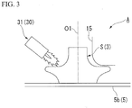
Fig. 3 is a view illustrating the forming device for a disk-shaped component and the forming method for a disk-shaped component according to an embodiment of the present invention, illustrating a case in which a burner is used as a heat retaining device. -
Fig. 4 is a view (a part indicated by (a) is a plan view, and a part indicated by (b) is a side view) illustrating an example of a range in which a material is heated (heat retained) by a heat retaining device, in the forming method for a disk-shaped component according to an embodiment of the present invention. -
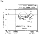
Fig. 5 is a view illustrating measured temperatures of a material in a case where a material is heated (heat retained) with a burner as a heat retaining device and a case where a burner is not used. -
Fig. 6 is a view illustrating a material (impeller disk). -
Fig. 7 is a view illustrating setting conditions of a simulation when using the forming method for a disk-shaped component according to an embodiment of the present invention. -
Fig. 8 is a diagram illustrating simulation results when using the forming method for a disk-shaped component according to an embodiment of the present invention. -
Fig. 9 is a view illustrating a forming device for a disk-shaped component and a forming method for a disk-shaped component according to an embodiment of the present invention, illustrating a case in which a heater and a heat insulating material are used as the heat retaining device. -
Fig. 10 is a view illustrating a forming device for a disk-shaped component and a forming method for a disk-shaped component according to an embodiment of the present invention, and illustrates a case in which a radiation material is used as a heat retaining device. -
Fig. 11 is a view illustrating an impeller. - Hereinafter, a forming method for a disk-shaped component and a forming device for a disk-shaped component according to an embodiment of the present invention will be described with reference to
Figs. 1 to 8 and11 . - In the present embodiment, description will be given on the assumption that an impeller disk is formed. However, the forming method for the disk-shaped component and the forming device for the disk-shaped component of the present invention can be applied to manufacturing of all disk-shaped components that can be formed using roll forging, without being limited to an impeller disk.
- As illustrated in
Figs. 1 and2 , a forming device (disk roll device) A for a disk-shaped component of the present embodiment includes a forming table (table) 5, aclamp 6, and a formingprocessing unit 7. - The forming table 5 includes a
table base 5a, and atable plate 5b having a circular shape in a plan view which is rotatably mounted on thetable base 5a via bearings. Thetable plate 5b is formed of a metal or the like which is harder than a material S to be formed into an impeller disk (a disk-shaped component) 3 and has high heat resistance, and a ring-shaped gear is provided on the circumferential portion of thetable plate 5b. - An output gear of a
table driver 10, which has an electric motor or the like as a driving source, engages with the gear of the forming table 5. As a result, thetable plate 5b is driven by thetable driver 10 and is rotated in one direction around a central axis O1 extending in a vertical direction at a desired speed. - A
clamp 6 is disposed above the forming table 5 to face the upper surface of the forming table 5. Theclamp 6 includes aclamp shaft 11, aholder 12, and aclamp shaft elevator 13. - The
clamp shaft 11 is provided coaxially with the central axis O1 of the forming table 5. Theclamp shaft 11 passes through theholder 12 and is supported by theholder 12 to freely rotate about the axis O1 and to be freely slidable in the direction of the axis O1. Theclamp shaft elevator 13 is driven by an electric motor, a hydraulic cylinder or the like. Theclamp shaft elevator 13 is connected to the upper portion of theclamp shaft 11. Theclamp shaft 11 is vertically moved up and down by driving theclamp shaft elevator 13. - The forming
processing unit 7 is placed on the forming table 5 and presses and plastically deforms the material S held by theclamp 6 to form the material S into a predetermined disk shape. The formingprocessing unit 7 includes a formingroll 15, a formingroll moving device 16, and acontroller 17. - The forming
roll 15 is made of a metal harder than the material S, and is formed in a substantially ring shape. The formingroll 15 has a rollcircumferential surface 15a as a material pressing surface, aroll end surface 15b, and aroll shoulder surface 15c, on the outer circumferential surface side coming into contact with the material S. - The roll
circumferential surface 15a is a portion having a substantially constant outer diameter, and at the time of forming aninclined surface 3a of theimpeller disk 3, a portion expanding to the edge of the material S and the outercircumferential portion 3b of theimpeller disk 3 are pressurized and pressed against the forming table 5. The rollcircumferential surface 15a prevents tensile stress from acting on the outercircumferential portion 3b in the circumferential direction when the outer circumferential portion is expanded at the time of forming the material S. Further, the rollcircumferential surface 15a has an appropriate width dimension F with which a compressive stress can be applied by pressing the outercircumferential portion 3b pressed and expanded in the radial direction against the forming table 5. - The
roll shoulder surface 15c is a curved surface which smoothly connects theroll end surface 15b located toward the center of the forming table 5 and the rollcircumferential surface 15a. The radius of curvature of theroll shoulder surface 15c is set to be smaller than the radius of curvature of theinclined surface 3a of theimpeller disk 3. - The forming
roll 15 configured as described above is connected to one end portion of therotating shaft 18 extending in the horizontal direction. The rotatingshaft 18 is supported at a tip (lower end) portion of amovable roll support 19 extending in the vertical direction via abearing 20 to be freely rotatable about theaxis 02. Theroll end surface 15b of the formingroll 15 faces the central of the forming table 5. The formingroll 15 is able to be freely rotated about theaxis 02 extending horizontally by the rotatingshaft 18. - The
movable roll support 19 is movable in the vertical direction and in the horizontal direction by the formingroll moving device 16. The formingroll moving device 16 includes a vertical guide and a horizontal guide which independently guide the movement of themovable roll support 19 in the vertical direction and the horizontal direction, respectively, and a vertical movement unit and a horizontal movement unit which move themovable roll support 19 along the guide, using a servo motor or the like as a driving source. - The
controller 17 controls the driving of the formingroll moving device 16. When the formingroll 15 is in contact with the material S, thecontroller 17 controls a driving source such as a servo motor such that it relatively moves the formingroll 15 with respect to the table 5 along the target shape of theimpeller disk 3, while maintaining a state in which its tangential speed is constant. - The forming
processing unit 7, thetable driver 10, and theclamp shaft elevator 13 are controlled by thecontrol unit 25, respectively. Aninput unit 26 such as a keyboard is connected to thecontrol unit 25. Rotation and stopping of the forming table 5 are controlled in accordance with input information regarding the specifications such as the shape and size of theimpeller disk 3 given by theinput unit 26, the ascending and descending of theclamp shaft 11 are controlled, and the movement of the formingroll 15 due to the formingroll moving device 16 is controlled. - When forming the
impeller disk 3 into the forming target shape, using the forming device A for the disk-shaped components of this embodiment having the above configuration, first, a material S1 which is cut to an appropriate size from a forging round bar is prepared, and the material S1 is processed to manufacture a columnar material S (S2) of a predetermined shape. - Subsequently, the material S made into a predetermined shape is heated to a predetermined temperature, and the high-temperature material S is placed on the central portion of the
table plate 5b of the forming table 5. Next, theclamp shaft 11 is lowered by driving theclamp shaft elevator 13. As a result, thepresser end portion 11a is pressed into the central portion of the material S such that it digs in from above, and the material S is held between the forming table 5 and theclamp 6. In a state in which the material S is set as described above, the forming table 5 is rotationally driven by the driving of thetable driver 10. - Next, by driving the forming
roll moving device 16, the formingroll 15 is pressed against the material S from above via themovable roll support 19. The formingroll 15 freely rotatable rotates in the rotational direction of the material S due to the pressing (pressurization, loading). Pressuring of the formingroll 15 on the material S in the pressed state is performed by moving the formingroll 15 from the central portion toward the outer circumferential portion of the forming table 5, while gradually bringing the formingroll 15 closer to the forming table 5, while keeping the tangential speed of the formingroll 15 constant. At this time, the movement of the formingroll 15 along the target shape of theimpeller disk 3 is two-dimensionally controlled by thecontroller 17. - Thus, due to the plastic deformation of the material S in a hot state due to the forming
roll 15, an envelope surface along a movement trajectory G of the formingroll 15, that is, aninclined surface 3a is formed on the material S to form theimpeller disk 3. - Here, the forming device A for a disk-shaped component of the present embodiment includes a
heat retaining device 30 for heat-retaining the material so that the temperature of the material S does not drop below a predetermined temperature during forming. - Further, in this embodiment, as illustrated in
Fig. 3 , a burner (gas burner) 31 may be used as theheat retaining device 30. Further, as illustrated inFig. 4 , theburner 31 as theheat retaining device 30 radiates a flame in an angular range θ of 20° to 180°, preferably in an angular range θ of 90°, in the circumferential direction around the rotational axis O1 of the material S rotating together with the forming table 5 to heat the material S. In addition, in the present embodiment, theburner 31 is disposed to radiate a flame to a part on the upstream side in the rotational direction with respect to the formingroll 15, so that the heated material S is pressurized by the formingroll 15 at an early stage. - Further, in the present embodiment, as illustrated in
Fig. 4 , a part of the rotating material S on the upstream side in the rotational direction with respect to the formingroll 15 is divided into inner circumferential sides ((1), (4)) and outer circumferential sides ((2), (5)) of the upper surface, and side surfaces (outer circumferential surfaces) ((3), (6)) forming the outer circumference of the material S, the angular range θ of 90° in the circumferential direction is divided into two sections at 45°, and the angular range θ of 90° of the material S is divided into 6 sections ((1) to (6)) in total. Aburner 31 is provided to heat each of individual sections (a total of three places) on the inner circumference side (1), the outer circumference side (5) and the side surfaces (3) among the divided six sections ((1) to (6)). - Here,
Fig. 5 illustrates the temperature measurement results of the material S in a case where the material S is formed while heating (heat retaining) the material S with theburner 31 as theheat retaining device 30 as described above, using the forming device A having a maximum loaded weight of about 600 tons, and in a case where the material S is formed without using theheat retaining device 30. - In
Fig. 5 , a line indicated by (a) illustrates the temperature measurement results of the side surface of the central portion of the material S (theinclined surface 3a of the impeller disk 3), a line indicated by (b) illustrates the temperature measurement results of an outer circumferential side of the upper surface of the material S, a line indicated by (c) illustrates the temperature measurement results of the outer circumferential edge portion of the upper surface of the material S, and a line indicated by (d) illustrates the temperature measurement results of the side surface of the material S (seeFig. 6 ). - As illustrated in
Fig. 5 , when the material S is extracted from the furnace and is formed without using theheat retaining device 30 from the start of forming to the completion of forming, it was confirmed that the temperature of the material S during forming decreased from about 1,050° to about 900° and decreased to about 700° on the side surface of the material S, due to heat dissipation into the atmosphere, heat release through the table 5, and the like. - In contrast, in the case of forming the material S while heating the material S using the
burner 31 as theheat retaining device 30, it was confirmed that a large temperature reduction did not occur from the start of forming to the completion of forming, that is, during forming. - Furthermore, in the case of forming the material S while heating the material S using the
burner 31 as theheat retaining device 30, it was confirmed that the load (forming load, reaction force) during forming has been reduced by 100 to 150 tons, as compared with the case of forming the material S without using theheat retaining device 30. - Next, as illustrated in Table 1, while having a precondition that the
burner 31 as theheat retaining device 30 is used, a simulation was performed under each of sets of conditions (Case 1,Case 2, and Case 3) in which the heat transfer coefficients for the material S of the formingroll 15, the table 5, or theclamp 6, and the initial temperature of the material S were changed, and the results of the forming analysis were compared and examined.[Table 1] Analysis condition Case 1 Case 2Case 3Roll Initial temperature (°C) 100 100 100 Heat transfer coefficient for material (w/m2k) 373 373 373 Table Initial temperature (°C) 100 100 100 Heat transfer coefficient for material (w/m2k) 373 373 373 Clamp Initial temperature (°C) 100 100 100 Heat transfer coefficient for material (w/m2k) 373 373 373 Material Initial temperature (°C) 1050 1050 1170 Heat transfer coefficient for periphery (w/m2k) 6 0 6 Emissivity to surroundings (%) 0.87 0 0.87 - In the simulation, SUS630 was used as the material S, and the
impeller disk 3 having an outer diameter of 1,500 mm was formed. Further, the initial material shape had a diameter of 660 mm and a thickness of 320 mm (seeFig. 7 ). -
Fig. 8 illustrates the results of the forming analysis ofCase 1,Case 2, andCase 3 illustrated in Table 1. As illustrated inFig. 1 , when simulating the forming method for the disk-shaped component according to the present embodiment using theburner 31 as the heat retaining device 30 (Case 2 and Case 3), it was confirmed that theimpeller disk 3 of 1,500 mm could be formed, without reaching the maximum loaded weight of 600 tons. It was also confirmed that the result of the forming analysis was within 7.5% of the load accuracy with respect to testing of an actual machine by performing the test on an actual machine under the same conditions. - In this way, by forming the material S while heating the material S using the
burner 31 as theheat retaining device 30, the decrease in temperature of the material S is suppressed, and the forming load can be greatly reduced. As a result, it was confirmed that a large-sized impeller disk 3 having an outer diameter of 1,500 mm could be suitably manufactured by roll forging. - Therefore, in the forming method for the disk-shaped component and the forming device A for the disk-shaped component according to the present embodiment, when the disk-shaped
component 3 such as the impeller disk is formed by roll forging, by heating (keeping warm/heat-insulating) the rotating material S using theheat retaining device 30, it is possible to suppress the decrease in temperature of the material S during forming. This makes it possible to inhibit or prevent the occurrence of forming load exceeding the equipment capacity due to the decrease in temperature of the material S or the occurrence of shape failure. - Therefore, for example, even in the existing equipment for roll forging in which the maximum loaded weight is about 600 tons and which is difficult to apply to large size forming when an outer diameter exceeds 1,350 mm, by adding the
heat retaining device 30, it is possible to make this applicable to (support) manufacturing of molded articles of a large size exceeding 1,350 mm. - Further, in the forming method for the disk-shaped component according to the present embodiment, it is possible to suppress the decrease in temperature of the material S during forming, by emitting a flame toward the material S using the
burner 31 as theheat retaining device 30. As a result, it is possible to reliably inhibit or prevent occurrence of forming load exceeding the equipment capacity during forming or occurrence of shape failure in the molded article. - Further, by heating the material with the
burner 31 as theheat retaining device 30, it is possible to set the deformation resistance of the material S to a predetermined value suitable for roll forging, for example, 20 kgf/mm2 or less. As a result, the material S can be easily deformed, and efficiently formed. - Further, by heating the angular range θ of 20° to 90° in the circumferential direction of the rotating material S using the
heat retaining device 30, it is possible to sufficiently suppress the decrease in temperature of the material S by theheat retaining device 30, while preventing occurrence of problems regarding the loaded weight applied to the material S by the formingroll 15. - Further, by heating the inner circumferential side of the upper surface of the material S, the outer circumferential side of the upper surface of the material S, and the side surface forming the outer circumference of the material S with the
heat retaining device 30, it is possible to more sufficiently suppress the decrease in temperature of the material S. - Although one embodiment of the forming method for the disk-shaped component and the forming device for the disk-shaped component according to the present invention has been described above, the present invention is not limited to the above-described embodiment, and various modifications may be made within the scope that does not depart from the scope of the invention.
- For example, in the present embodiment, the
burner 31 is used as theheat retaining device 30. However, as illustrated inFig. 9 , an electric heater or an IH (Induction Heating)heater 32 may be used as theheat retaining device 30, and the material S may be formed while heating the rotating material S by the electric heater or theIH heater 32 from the outer side. - Further, as illustrated in
Figs. 9 and 10 , at least one of aheat insulating material 33 and aradiation material 34 may be used as theheat retaining device 30, and the material S may be formed by disposing at least one of theheat insulating material 33 and theradiation material 34 on the outer side of the rotating material S. - With the
heater 32, theheat insulating material 33, and theradiation material 34, it is also possible to suppress the decrease in temperature of the material S during forming as in this embodiment. Therefore, it is possible to inhibit or prevent the occurrence of a forming load exceeding the equipment capacity during forming or the occurrence of a shape failure in a molded article. That is, even in the existing equipment of roll forging which has a maximum loaded weight of about 600 tons and is difficult to apply to large-size forming when an outer diameter exceeds 1,350 mm, by adding theheater 32, theheat insulating material 33, or theradiation material 34 asheat retaining devices 30, it is possible to make this applicable to (support) manufacturing of a molded article of a large size exceeding 1,350 mm. - Further, it is possible to perform forming by appropriately selectively providing (using) the
burners 31,heaters 32,heat insulating materials 33, andradiation materials 34 as theheat retaining device 30. - Further, in the present embodiment, the description has been made on the assumption that the maximum loaded weight of the forming device A is about 600 tons and a molded article having a size of an outer diameter exceeding 1,350 mm is manufactured, but it is also possible to apply the present invention to a forming device A smaller than 600 tons or a forming device A which has a maximum loaded weight of 600 tons or more. In addition, the size of the disk-shaped component to be molded by applying the present invention is also not limited.
- In the above-described forming method for the disk-shaped component and the forming device for the disk-shaped component, when forming a disk-shaped component such as an impeller disk by roll forging, it is possible to prevent the decrease in temperature of the rotating material during forming by heating/insulating the rotating material using a heat retaining device. This makes it possible to inhibit or prevent the occurrence of forming load exceeding the equipment capacity due to the decrease in temperature of the material or the occurrence of shape failure. Therefore, according to the forming method for a disk-shaped component and the forming device for a disk-shaped component of the present invention, for example, even with the existing equipment for roll-forging which is difficult to apply to forming with a large size outer diameter exceeding 1,350 mm, it is possible to make this applicable to (cope with) manufacturing of molded articles with a large size merely by adding a heat retaining device.
-
- 1
- Impeller
- 2
- Blade
- 3
- Impeller disk (disk-shaped component)
- 3 a
- Inclined surface
- 3b
- Outer circumferential portion
- 4
- Impeller cover (disk-shaped component)
- 5
- Forming table (table)
- 5a
- Table base
- 5b
- Table plate
- 6
- Clamp
- 7
- Forming processing unit
- 10
- Table driver
- 11
- Clamp shaft
- 11a
- Presser end portion
- 12
- Holder
- 13
- Clamp shaft elevator
- 15
- Forming roll
- 15a
- Roll circumferential surface
- 15b
- Roll end surface
- 15c
- Roll shoulder surface
- 16
- Forming roll moving device
- 17
- Control unit
- 18
- Rotating shaft
- 19
- Movable roll support
- 20
- Bearing
- 25
- Control unit
- 26
- Input unit
- 30
- Heat retaining device
- 31
- Burner
- 32
- Heater
- 33
- Heat insulating material
- 34
- Radiation material
- A
- Forming device for disk-shaped component (disk roll device)
- O1
- Central axis (axis)
- O2
- Axis
- S
- Material
Claims (7)
- A forming method for a disk-shaped component, the method comprising:mounting a heated material on a table;applying a load to the material with a forming roll, while rotating the material by rotating the table;forming the material into a disk shape by roll forging; andsuppressing decrease in temperature of the material during forming using a heat retaining device.
- The forming method according to claim 1, wherein a burner is used as the heat retaining device, and
the material is formed while heating the material by emitting a flame toward the rotating material. - The forming method according to claim 1 or 2, wherein using an electric heater or an IH heater is used as the heat retaining device, and
the material is formed while heating the rotating material with the heater from the outer side. - The forming method according to any one of claims 1 to 3, wherein at least one of a heat insulating material and a radiation material is used as the heat retaining device, and
the material is formed by disposing at least one of the heat insulating material and the radiation material on the outer side of the rotating material. - The forming method according to any one of claims 1 to 4, wherein the heat retaining device is disposed in a range of 20° to 180° in the circumferential direction about a rotational axis of the material, and the rotating material is heated or insulated by the heat retaining device in the range of 20° to 180° in the circumferential direction to suppress decrease in temperature of the material.
- The forming method according to any one of claims 1 to 5, wherein an inner circumferential side and an outer circumferential side of the upper surface of the rotating material, and a side surface forming the outer circumference are heated/insulated by the heat retaining device to suppress decrease in temperature of the material.
- A forming device for a disk-shaped component which mounts a heated material on a table, applies a load to the material with a forming roll, while rotating the table by rotating the material, and forms the material into a disk shape by roll forging, the forming device comprising:a heat retaining device which suppresses decrease in temperature of the material during forming.
Applications Claiming Priority (2)
| Application Number | Priority Date | Filing Date | Title |
|---|---|---|---|
| JP2015037212A JP6687326B2 (en) | 2015-02-26 | 2015-02-26 | Impeller disk molding method and impeller disk molding apparatus |
| PCT/JP2015/079956 WO2016136022A1 (en) | 2015-02-26 | 2015-10-23 | Forming method for disk-shaped component and forming device for disk-shaped component |
Publications (2)
| Publication Number | Publication Date |
|---|---|
| EP3251772A1 true EP3251772A1 (en) | 2017-12-06 |
| EP3251772A4 EP3251772A4 (en) | 2018-03-21 |
Family
ID=56788116
Family Applications (1)
| Application Number | Title | Priority Date | Filing Date |
|---|---|---|---|
| EP15883312.9A Withdrawn EP3251772A4 (en) | 2015-02-26 | 2015-10-23 | Forming method for disk-shaped component and forming device for disk-shaped component |
Country Status (4)
| Country | Link |
|---|---|
| US (1) | US10300522B2 (en) |
| EP (1) | EP3251772A4 (en) |
| JP (1) | JP6687326B2 (en) |
| WO (1) | WO2016136022A1 (en) |
Family Cites Families (13)
| Publication number | Priority date | Publication date | Assignee | Title |
|---|---|---|---|---|
| GB300230A (en) | 1927-08-09 | 1928-11-09 | John William Smith | Means for rolling disk wheels and the like |
| JPS62207525A (en) | 1986-03-06 | 1987-09-11 | Nippon Kokan Kk <Nkk> | ring mill rolling equipment |
| JPH05285581A (en) * | 1992-04-14 | 1993-11-02 | Kobe Steel Ltd | Device for warm spinning |
| JPH0818210B2 (en) * | 1992-05-15 | 1996-02-28 | 健 柳沢 | Two-dimensional movement mechanism |
| RU2031753C1 (en) | 1992-07-21 | 1995-03-27 | Всероссийский научно-исследовательский институт технической физики | Device to roll out |
| JPH0623637U (en) * | 1992-08-24 | 1994-03-29 | 株式会社神戸製鋼所 | Vehicle wheel molding equipment |
| DE19545177B4 (en) | 1995-12-04 | 2005-11-17 | Leifeld Metal Spinning Gmbh | Method for spin forming a workpiece |
| JP3680001B2 (en) * | 2001-03-07 | 2005-08-10 | 三菱重工業株式会社 | Disc-shaped part molding method and molding apparatus |
| US20040134249A1 (en) | 2003-01-09 | 2004-07-15 | Utiashev Farid Zaynullaevich | Method and device for making intricately-shaped axisymmetric parts from hardly deformable polyphase alloys |
| JP2008018446A (en) * | 2006-07-12 | 2008-01-31 | Toyota Motor Corp | Hot rotating sequential forging method and apparatus |
| JP2012030234A (en) * | 2010-07-28 | 2012-02-16 | Nippon Spindle Mfg Co Ltd | Rotational plastic working apparatus and operation method for rotational plastic working apparatus |
| US20120279268A1 (en) | 2011-05-03 | 2012-11-08 | Loveless Don L | Forging of an Annular Article with Electric Induction Heating |
| JP2013220464A (en) * | 2012-04-19 | 2013-10-28 | Asahi Tec Corp | Method of manufacturing vehicular wheel |
-
2015
- 2015-02-26 JP JP2015037212A patent/JP6687326B2/en not_active Expired - Fee Related
- 2015-10-23 WO PCT/JP2015/079956 patent/WO2016136022A1/en not_active Ceased
- 2015-10-23 EP EP15883312.9A patent/EP3251772A4/en not_active Withdrawn
- 2015-10-23 US US15/553,496 patent/US10300522B2/en not_active Expired - Fee Related
Also Published As
| Publication number | Publication date |
|---|---|
| JP6687326B2 (en) | 2020-04-22 |
| US20180056366A1 (en) | 2018-03-01 |
| WO2016136022A1 (en) | 2016-09-01 |
| JP2016159299A (en) | 2016-09-05 |
| US10300522B2 (en) | 2019-05-28 |
| EP3251772A4 (en) | 2018-03-21 |
Similar Documents
| Publication | Publication Date | Title |
|---|---|---|
| CN109622865B (en) | Forging method of GH4169 series high-temperature alloy turbine disc for aero-engine | |
| JP6180558B2 (en) | Press system and method | |
| JP2017515689A (en) | Method of forming parts from sheet metal alloy | |
| CN104726678B (en) | Pressure heat treatment equipment of ultrathin circular saw web and application method of pressure heat treatment equipment | |
| CN102554584B (en) | For the manufacture of the method for the leading screw with big bearing support position | |
| JP5010824B2 (en) | Upset method for processing metal slag and apparatus for performing the method | |
| JP2016144814A (en) | Hot forging mold device and hot forging method using the same | |
| US10300522B2 (en) | Forming method for disk-shaped component and forming device for disk-shaped component | |
| CN103464504A (en) | Production method of cold pressing mold | |
| JP5994676B2 (en) | Glass molded body manufacturing apparatus and glass molded body manufacturing method | |
| JP6047802B2 (en) | Glass molded body manufacturing apparatus and glass molded body manufacturing method | |
| CN101569898B (en) | Manufacture method of target material | |
| US9744578B2 (en) | Crystal growth crucible re-shaper | |
| JP6508568B2 (en) | Method of correcting shape of material for turbine blade and method of manufacturing material for turbine blade | |
| CN112779382B (en) | Heat treatment method for hot work die steel | |
| EP3137243B1 (en) | Forging dies with internal heating system | |
| JP5036165B2 (en) | Mold quenching method and restraint type device for ring-shaped product | |
| JP3680001B2 (en) | Disc-shaped part molding method and molding apparatus | |
| KR20120132371A (en) | Roller leveler and, metal plate processing equipment and processing method using thereof | |
| CN101837635B (en) | Pressing method of ultra-high molecular weight polyethylene grease storage pit | |
| Mulyukov et al. | Technological features of a process and equipment for superplastic rolling of axially symmetric heat-resistant alloy components of rotors for modern aircraft engines | |
| JP6216894B1 (en) | Cylindrical member forming device | |
| JP5036168B2 (en) | Mold quenching method and restraint type device for ring-shaped product | |
| Alawadhi et al. | Evolution of homogeneity in oxygen-free copper processed by either ECAP or HPT | |
| EP2915888A1 (en) | Carburizing and quenching facility |
Legal Events
| Date | Code | Title | Description |
|---|---|---|---|
| PUAI | Public reference made under article 153(3) epc to a published international application that has entered the european phase |
Free format text: ORIGINAL CODE: 0009012 |
|
| 17P | Request for examination filed |
Effective date: 20170825 |
|
| AK | Designated contracting states |
Kind code of ref document: A1 Designated state(s): AL AT BE BG CH CY CZ DE DK EE ES FI FR GB GR HR HU IE IS IT LI LT LU LV MC MK MT NL NO PL PT RO RS SE SI SK SM TR |
|
| AX | Request for extension of the european patent |
Extension state: BA ME |
|
| A4 | Supplementary search report drawn up and despatched |
Effective date: 20180219 |
|
| RIC1 | Information provided on ipc code assigned before grant |
Ipc: B21H 1/02 20060101AFI20180212BHEP Ipc: B21J 1/06 20060101ALI20180212BHEP |
|
| DAV | Request for validation of the european patent (deleted) | ||
| DAX | Request for extension of the european patent (deleted) | ||
| STAA | Information on the status of an ep patent application or granted ep patent |
Free format text: STATUS: THE APPLICATION IS DEEMED TO BE WITHDRAWN |
|
| 18D | Application deemed to be withdrawn |
Effective date: 20180919 |