EP3250063B1 - Textile or fabric with attached flexible and conformable light source apparatus - Google Patents
Textile or fabric with attached flexible and conformable light source apparatus Download PDFInfo
- Publication number
- EP3250063B1 EP3250063B1 EP15823838.6A EP15823838A EP3250063B1 EP 3250063 B1 EP3250063 B1 EP 3250063B1 EP 15823838 A EP15823838 A EP 15823838A EP 3250063 B1 EP3250063 B1 EP 3250063B1
- Authority
- EP
- European Patent Office
- Prior art keywords
- light source
- flexible
- textile
- fabric
- garment
- Prior art date
- Legal status (The legal status is an assumption and is not a legal conclusion. Google has not performed a legal analysis and makes no representation as to the accuracy of the status listed.)
- Active
Links
Images




Classifications
-
- A—HUMAN NECESSITIES
- A41—WEARING APPAREL
- A41B—SHIRTS; UNDERWEAR; BABY LINEN; HANDKERCHIEFS
- A41B1/00—Shirts
- A41B1/08—Details
-
- A—HUMAN NECESSITIES
- A41—WEARING APPAREL
- A41B—SHIRTS; UNDERWEAR; BABY LINEN; HANDKERCHIEFS
- A41B11/00—Hosiery; Panti-hose
-
- A—HUMAN NECESSITIES
- A41—WEARING APPAREL
- A41D—OUTERWEAR; PROTECTIVE GARMENTS; ACCESSORIES
- A41D1/00—Garments
- A41D1/06—Trousers
-
- A—HUMAN NECESSITIES
- A41—WEARING APPAREL
- A41D—OUTERWEAR; PROTECTIVE GARMENTS; ACCESSORIES
- A41D13/00—Professional, industrial or sporting protective garments, e.g. surgeons' gowns or garments protecting against blows or punches
- A41D13/01—Professional, industrial or sporting protective garments, e.g. surgeons' gowns or garments protecting against blows or punches with reflective or luminous safety means
-
- A—HUMAN NECESSITIES
- A41—WEARING APPAREL
- A41D—OUTERWEAR; PROTECTIVE GARMENTS; ACCESSORIES
- A41D27/00—Details of garments or of their making
- A41D27/08—Trimmings; Ornaments
- A41D27/085—Luminous ornaments
-
- A—HUMAN NECESSITIES
- A41—WEARING APPAREL
- A41D—OUTERWEAR; PROTECTIVE GARMENTS; ACCESSORIES
- A41D29/00—Uniforms; Parts or accessories of uniforms
-
- A—HUMAN NECESSITIES
- A42—HEADWEAR
- A42B—HATS; HEAD COVERINGS
- A42B1/00—Hats; Caps; Hoods
- A42B1/24—Hats; Caps; Hoods with means for attaching articles thereto, e.g. memorandum tablets or mirrors
- A42B1/242—Means for mounting detecting, signalling or lighting devices
-
- A—HUMAN NECESSITIES
- A43—FOOTWEAR
- A43B—CHARACTERISTIC FEATURES OF FOOTWEAR; PARTS OF FOOTWEAR
- A43B3/00—Footwear characterised by the shape or the use
- A43B3/34—Footwear characterised by the shape or the use with electrical or electronic arrangements
- A43B3/36—Footwear characterised by the shape or the use with electrical or electronic arrangements with light sources
-
- B—PERFORMING OPERATIONS; TRANSPORTING
- B65—CONVEYING; PACKING; STORING; HANDLING THIN OR FILAMENTARY MATERIAL
- B65D—CONTAINERS FOR STORAGE OR TRANSPORT OF ARTICLES OR MATERIALS, e.g. BAGS, BARRELS, BOTTLES, BOXES, CANS, CARTONS, CRATES, DRUMS, JARS, TANKS, HOPPERS, FORWARDING CONTAINERS; ACCESSORIES, CLOSURES, OR FITTINGS THEREFOR; PACKAGING ELEMENTS; PACKAGES
- B65D29/00—Sacks or like containers made of fabrics; Flexible containers of open-work, e.g. net-like construction
-
- B—PERFORMING OPERATIONS; TRANSPORTING
- B65—CONVEYING; PACKING; STORING; HANDLING THIN OR FILAMENTARY MATERIAL
- B65D—CONTAINERS FOR STORAGE OR TRANSPORT OF ARTICLES OR MATERIALS, e.g. BAGS, BARRELS, BOTTLES, BOXES, CANS, CARTONS, CRATES, DRUMS, JARS, TANKS, HOPPERS, FORWARDING CONTAINERS; ACCESSORIES, CLOSURES, OR FITTINGS THEREFOR; PACKAGING ELEMENTS; PACKAGES
- B65D33/00—Details of, or accessories for, sacks or bags
- B65D33/004—Information or decoration elements, e.g. level indicators, detachable tabs or coupons
-
- D—TEXTILES; PAPER
- D02—YARNS; MECHANICAL FINISHING OF YARNS OR ROPES; WARPING OR BEAMING
- D02G—CRIMPING OR CURLING FIBRES, FILAMENTS, THREADS, OR YARNS; YARNS OR THREADS
- D02G3/00—Yarns or threads, e.g. fancy yarns; Processes or apparatus for the production thereof, not otherwise provided for
- D02G3/44—Yarns or threads characterised by the purpose for which they are designed
- D02G3/441—Yarns or threads with antistatic, conductive or radiation-shielding properties
-
- F—MECHANICAL ENGINEERING; LIGHTING; HEATING; WEAPONS; BLASTING
- F21—LIGHTING
- F21S—NON-PORTABLE LIGHTING DEVICES; SYSTEMS THEREOF; VEHICLE LIGHTING DEVICES SPECIALLY ADAPTED FOR VEHICLE EXTERIORS
- F21S9/00—Lighting devices with a built-in power supply; Systems employing lighting devices with a built-in power supply
- F21S9/02—Lighting devices with a built-in power supply; Systems employing lighting devices with a built-in power supply the power supply being a battery or accumulator
-
- F—MECHANICAL ENGINEERING; LIGHTING; HEATING; WEAPONS; BLASTING
- F21—LIGHTING
- F21V—FUNCTIONAL FEATURES OR DETAILS OF LIGHTING DEVICES OR SYSTEMS THEREOF; STRUCTURAL COMBINATIONS OF LIGHTING DEVICES WITH OTHER ARTICLES, NOT OTHERWISE PROVIDED FOR
- F21V19/00—Fastening of light sources or lamp holders
- F21V19/001—Fastening of light sources or lamp holders the light sources being semiconductors devices, e.g. LEDs
- F21V19/0015—Fastening arrangements intended to retain light sources
-
- F—MECHANICAL ENGINEERING; LIGHTING; HEATING; WEAPONS; BLASTING
- F21—LIGHTING
- F21V—FUNCTIONAL FEATURES OR DETAILS OF LIGHTING DEVICES OR SYSTEMS THEREOF; STRUCTURAL COMBINATIONS OF LIGHTING DEVICES WITH OTHER ARTICLES, NOT OTHERWISE PROVIDED FOR
- F21V23/00—Arrangement of electric circuit elements in or on lighting devices
- F21V23/02—Arrangement of electric circuit elements in or on lighting devices the elements being transformers, impedances or power supply units, e.g. a transformer with a rectifier
-
- F—MECHANICAL ENGINEERING; LIGHTING; HEATING; WEAPONS; BLASTING
- F21—LIGHTING
- F21V—FUNCTIONAL FEATURES OR DETAILS OF LIGHTING DEVICES OR SYSTEMS THEREOF; STRUCTURAL COMBINATIONS OF LIGHTING DEVICES WITH OTHER ARTICLES, NOT OTHERWISE PROVIDED FOR
- F21V23/00—Arrangement of electric circuit elements in or on lighting devices
- F21V23/04—Arrangement of electric circuit elements in or on lighting devices the elements being switches
- F21V23/0442—Arrangement of electric circuit elements in or on lighting devices the elements being switches activated by means of a sensor, e.g. motion or photodetectors
-
- F—MECHANICAL ENGINEERING; LIGHTING; HEATING; WEAPONS; BLASTING
- F21—LIGHTING
- F21V—FUNCTIONAL FEATURES OR DETAILS OF LIGHTING DEVICES OR SYSTEMS THEREOF; STRUCTURAL COMBINATIONS OF LIGHTING DEVICES WITH OTHER ARTICLES, NOT OTHERWISE PROVIDED FOR
- F21V23/00—Arrangement of electric circuit elements in or on lighting devices
- F21V23/04—Arrangement of electric circuit elements in or on lighting devices the elements being switches
- F21V23/0442—Arrangement of electric circuit elements in or on lighting devices the elements being switches activated by means of a sensor, e.g. motion or photodetectors
- F21V23/0464—Arrangement of electric circuit elements in or on lighting devices the elements being switches activated by means of a sensor, e.g. motion or photodetectors the sensor sensing the level of ambient illumination, e.g. dawn or dusk sensors
-
- F—MECHANICAL ENGINEERING; LIGHTING; HEATING; WEAPONS; BLASTING
- F21—LIGHTING
- F21V—FUNCTIONAL FEATURES OR DETAILS OF LIGHTING DEVICES OR SYSTEMS THEREOF; STRUCTURAL COMBINATIONS OF LIGHTING DEVICES WITH OTHER ARTICLES, NOT OTHERWISE PROVIDED FOR
- F21V23/00—Arrangement of electric circuit elements in or on lighting devices
- F21V23/04—Arrangement of electric circuit elements in or on lighting devices the elements being switches
- F21V23/0442—Arrangement of electric circuit elements in or on lighting devices the elements being switches activated by means of a sensor, e.g. motion or photodetectors
- F21V23/0471—Arrangement of electric circuit elements in or on lighting devices the elements being switches activated by means of a sensor, e.g. motion or photodetectors the sensor detecting the proximity, the presence or the movement of an object or a person
-
- F—MECHANICAL ENGINEERING; LIGHTING; HEATING; WEAPONS; BLASTING
- F21—LIGHTING
- F21V—FUNCTIONAL FEATURES OR DETAILS OF LIGHTING DEVICES OR SYSTEMS THEREOF; STRUCTURAL COMBINATIONS OF LIGHTING DEVICES WITH OTHER ARTICLES, NOT OTHERWISE PROVIDED FOR
- F21V23/00—Arrangement of electric circuit elements in or on lighting devices
- F21V23/06—Arrangement of electric circuit elements in or on lighting devices the elements being coupling devices, e.g. connectors
-
- F—MECHANICAL ENGINEERING; LIGHTING; HEATING; WEAPONS; BLASTING
- F21—LIGHTING
- F21V—FUNCTIONAL FEATURES OR DETAILS OF LIGHTING DEVICES OR SYSTEMS THEREOF; STRUCTURAL COMBINATIONS OF LIGHTING DEVICES WITH OTHER ARTICLES, NOT OTHERWISE PROVIDED FOR
- F21V3/00—Globes; Bowls; Cover glasses
-
- F—MECHANICAL ENGINEERING; LIGHTING; HEATING; WEAPONS; BLASTING
- F21—LIGHTING
- F21V—FUNCTIONAL FEATURES OR DETAILS OF LIGHTING DEVICES OR SYSTEMS THEREOF; STRUCTURAL COMBINATIONS OF LIGHTING DEVICES WITH OTHER ARTICLES, NOT OTHERWISE PROVIDED FOR
- F21V33/00—Structural combinations of lighting devices with other articles, not otherwise provided for
- F21V33/0004—Personal or domestic articles
- F21V33/0008—Clothing or clothing accessories, e.g. scarfs, gloves or belts
-
- F—MECHANICAL ENGINEERING; LIGHTING; HEATING; WEAPONS; BLASTING
- F21—LIGHTING
- F21V—FUNCTIONAL FEATURES OR DETAILS OF LIGHTING DEVICES OR SYSTEMS THEREOF; STRUCTURAL COMBINATIONS OF LIGHTING DEVICES WITH OTHER ARTICLES, NOT OTHERWISE PROVIDED FOR
- F21V7/00—Reflectors for light sources
- F21V7/04—Optical design
-
- H—ELECTRICITY
- H05—ELECTRIC TECHNIQUES NOT OTHERWISE PROVIDED FOR
- H05B—ELECTRIC HEATING; ELECTRIC LIGHT SOURCES NOT OTHERWISE PROVIDED FOR; CIRCUIT ARRANGEMENTS FOR ELECTRIC LIGHT SOURCES, IN GENERAL
- H05B47/00—Circuit arrangements for operating light sources in general, i.e. where the type of light source is not relevant
- H05B47/10—Controlling the light source
- H05B47/105—Controlling the light source in response to determined parameters
- H05B47/11—Controlling the light source in response to determined parameters by determining the brightness or colour temperature of ambient light
-
- H—ELECTRICITY
- H05—ELECTRIC TECHNIQUES NOT OTHERWISE PROVIDED FOR
- H05B—ELECTRIC HEATING; ELECTRIC LIGHT SOURCES NOT OTHERWISE PROVIDED FOR; CIRCUIT ARRANGEMENTS FOR ELECTRIC LIGHT SOURCES, IN GENERAL
- H05B47/00—Circuit arrangements for operating light sources in general, i.e. where the type of light source is not relevant
- H05B47/10—Controlling the light source
- H05B47/105—Controlling the light source in response to determined parameters
- H05B47/115—Controlling the light source in response to determined parameters by determining the presence or movement of objects or living beings
- H05B47/12—Controlling the light source in response to determined parameters by determining the presence or movement of objects or living beings by detecting audible sound
-
- A—HUMAN NECESSITIES
- A41—WEARING APPAREL
- A41D—OUTERWEAR; PROTECTIVE GARMENTS; ACCESSORIES
- A41D2600/00—Uses of garments specially adapted for specific purposes
- A41D2600/20—Uses of garments specially adapted for specific purposes for working activities
-
- F—MECHANICAL ENGINEERING; LIGHTING; HEATING; WEAPONS; BLASTING
- F21—LIGHTING
- F21Y—INDEXING SCHEME ASSOCIATED WITH SUBCLASSES F21K, F21L, F21S and F21V, RELATING TO THE FORM OR THE KIND OF THE LIGHT SOURCES OR OF THE COLOUR OF THE LIGHT EMITTED
- F21Y2115/00—Light-generating elements of semiconductor light sources
- F21Y2115/10—Light-emitting diodes [LED]
-
- F—MECHANICAL ENGINEERING; LIGHTING; HEATING; WEAPONS; BLASTING
- F21—LIGHTING
- F21Y—INDEXING SCHEME ASSOCIATED WITH SUBCLASSES F21K, F21L, F21S and F21V, RELATING TO THE FORM OR THE KIND OF THE LIGHT SOURCES OR OF THE COLOUR OF THE LIGHT EMITTED
- F21Y2115/00—Light-generating elements of semiconductor light sources
- F21Y2115/10—Light-emitting diodes [LED]
- F21Y2115/15—Organic light-emitting diodes [OLED]
-
- F—MECHANICAL ENGINEERING; LIGHTING; HEATING; WEAPONS; BLASTING
- F21—LIGHTING
- F21Y—INDEXING SCHEME ASSOCIATED WITH SUBCLASSES F21K, F21L, F21S and F21V, RELATING TO THE FORM OR THE KIND OF THE LIGHT SOURCES OR OF THE COLOUR OF THE LIGHT EMITTED
- F21Y2115/00—Light-generating elements of semiconductor light sources
- F21Y2115/20—Electroluminescent [EL] light sources
-
- Y—GENERAL TAGGING OF NEW TECHNOLOGICAL DEVELOPMENTS; GENERAL TAGGING OF CROSS-SECTIONAL TECHNOLOGIES SPANNING OVER SEVERAL SECTIONS OF THE IPC; TECHNICAL SUBJECTS COVERED BY FORMER USPC CROSS-REFERENCE ART COLLECTIONS [XRACs] AND DIGESTS
- Y02—TECHNOLOGIES OR APPLICATIONS FOR MITIGATION OR ADAPTATION AGAINST CLIMATE CHANGE
- Y02B—CLIMATE CHANGE MITIGATION TECHNOLOGIES RELATED TO BUILDINGS, e.g. HOUSING, HOUSE APPLIANCES OR RELATED END-USER APPLICATIONS
- Y02B20/00—Energy efficient lighting technologies, e.g. halogen lamps or gas discharge lamps
- Y02B20/40—Control techniques providing energy savings, e.g. smart controller or presence detection
Definitions
- the current application relates to textiles or fabrics that include flexible and conformable light strips that are also washable as part of the textile or fabric.
- the current invention relates to garments that incorporate a flexible illumination/light device.
- GB 2 396 252 discloses a garment illumination system whereby LED lights are attached to fabrics.
- a device comprising a textile or fabric and a flexible and conformable light source apparatus attached to the textile or fabric, wherein the light source apparatus comprises at least one light source at least two conductive members having a first end and a second end, the first end is connected to the at least one light source and the second end is adapted to connect to a power source and at least one transparent polymer layer that encapsulates the entirety of the at least one light source and at least part of the at least two conductive members.
- the light source may be selected from one or more of the group consisting of a light emitting diode (LED), an organic light emitting diode (OLED) and an electroluminescent material, optionally wherein the light source further comprises an optical channelling device (e.g. an optical fibre).
- LED light emitting diode
- OLED organic light emitting diode
- electroluminescent material optionally wherein the light source further comprises an optical channelling device (e.g. an optical fibre).
- the light source may be attached to the textile or fabric by the at least one transparent polymer layer.
- the flexible and conformable light source apparatus may further comprise at least one flexible substrate with at least one electrical circuit thereon, where the at least one light source is attached to the at least one flexible substrate through the at least one electrical circuit and the at least one electrical circuit is connected to the at least two conductive members.
- the at least one light source may be attached to the at least one electrical circuit by an isotropic conductive adhesive or by soldering.
- the at least one electrical circuit may comprise silver and/or copper.
- the at least one electrical circuit is a printed electrical circuit or a lithographically etched electrical circuit.
- the conductive members may be one or more of the group selected from a wire, a conductive yarn, a screen-printed conductive path and combinations thereof.
- the device may further comprise a power supply unit and an electrical interconnect to connect the power supply unit to the light source apparatus.
- the electrical interconnect may comprise a first flexible interconnect component that is attached to the textile or fabric and to the second end of the at least two conductive members, comprising at least one first magnetic part and a first housing having a first contact surface, the first housing being adapted to securely hold the at least one first magnetic part, such that the at least one first magnetic part protrudes from the first contact surface and/or forms a recess in said surface, and a second flexible and/or rigid interconnect component that is attached to the power supply unit, comprising at least one second magnetic part and a second housing having a second contact surface, the second housing being adapted to securely hold the at least one second magnetic part, such that the at least one second magnetic part protrudes from the second contact surface and/or forms a recess in said surface, wherein, the at least one first and the at least one second magnetic parts are complementarily positioned in the first and second housings, respectively, to enable coupling of the first and second contact surfaces through magnetic interaction, electricity and/or signalling data is conducted through the first
- the electrical interconnect may further comprise a mechanical coupling mechanism, optionally wherein the mechanical coupling mechanism comprises at least one section containing at least one groove on the contact surface of the first housing arranged to releasably bind to a complementary projection on the contact surface of the second housing or vice versa.
- the mechanical coupling mechanism comprises at least one section containing at least one groove on the contact surface of the first housing arranged to releasably bind to a complementary projection on the contact surface of the second housing or vice versa.
- the at least one first magnetic part and the at least one second magnetic part of the first and second electrical interconnect components independently comprise from one to twenty magnets (e.g. from two to fifteen, such as three to eight magnets).
- the number of magnets of the first magnetic part and the number of magnets of the second magnetic part are different.
- each magnet may comprise a magnet core and a non-magnet, conductive outer shell, optionally wherein the conductive outer shell is one or more of a material selected from aluminium, copper, lead, nickel, tin, titanium, zinc, gold, silver, platinum, cobalt, lithium, tungsten, beryllium, bismuth, cerium, cadmium, niobium, indium, gallium, germanium, selenium, tantalum, tellurium, vanadium, zirconium and iron.
- a material selected from aluminium, copper, lead, nickel, tin, titanium, zinc, gold, silver, platinum, cobalt, lithium, tungsten, beryllium, bismuth, cerium, cadmium, niobium, indium, gallium, germanium, selenium, tantalum, tellurium, vanadium, zirconium and iron.
- the adaption of the first housing and/or the second housing to securely hold the respective at least one first and/or at least second magnetic part may comprise an individual hole in the respective housing for each individual magnet, where each individual hole in the respective housing is substantially perpendicular to the respective contact surface.
- each individual hole may independently be selected from a through-hole or a blind hole having at least one wall, where the at least one wall further comprises an aperture suitable for a flexible conductive member (e.g. a wire, metal strips or conductive yarns).
- the first housing may be made from one or more of a material selected from the group consisting of leather, a synthetic leather, a rexine, silicone, a hard fabric, flexible polyurethane, polyethylene napthalene, urethane, thermoplastic polyurethane (TPU), natural rubber and synthetic rubber.
- a material selected from the group consisting of leather, a synthetic leather, a rexine, silicone, a hard fabric, flexible polyurethane, polyethylene napthalene, urethane, thermoplastic polyurethane (TPU), natural rubber and synthetic rubber.
- the textile and/or fabric may be formed into a garment or a bag.
- the garment is selected from shorts, socks, T-shirts, trousers, leggings, shirts, caps, footwear and accessories (e.g. head bands, arm warmers, wristbands) uniforms for rescue workers, night patrol, construction or safety wear, winter sports, and mountaineering clothing and gear.
- the flexible and conformable light source apparatus may have a thickness that is less than or equal to 1000 ⁇ m (e.g. 750 ⁇ m). In alternative embodiments, the flexible and conformable light source apparatus may have a thickness that is less than or equal to 350 ⁇ m.
- the flexible and conformable light source apparatus may have a bending radius of from 0.001 mm to 10 mm, such as from 0.01 mm to 1 mm, from 1 mm to 10 mm, or less than or equal to 5 mm.
- the distance between the light sources is at least 0.1 cm
- the at least one transparent polymer layer may be a material selected from one or more of the group consisting of TPU, a silicone-based polymer, a plasma-treated textile substrate and a water repellent textile substrate, optionally wherein the at least one transparent polymer layer may be a material selected from one or more of the group consisting of TPU and a silicone-based polymer.
- the at least one light source is positioned to face towards the textile or fabric, optionally wherein an opening in the fabric or textile aligns with the at least one light source.
- the at least one light source may be positioned to face away from the textile or fabric.
- the flexible and conformable light source apparatus may further comprise at least one reflective object adjacent to the at least one light source on said plane and the at least one light source is positioned on the flexible substrate at an angle on said plane such that light generated from the at least one light source is reflected by the at least one reflective object.
- the at least one reflective object may have a shape selected from the group consisting of a prism, a sphere or part thereof, a concave cup shape, a retroreflective tunnel and one or more fibre optic cables.
- a “retroreflective tunnel” refers to a conduit having a clear outer layer and a retroreflective inner layer (or vice versa ), where the retroreflective layer contains gaps such that light may escape to cause the retroreflective tunnel to glow.
- the flexible substrate may be made from one or more of the group selected from polyethylene naphthalate, polyethylene terephthalate, polyimide.
- the device of the current invention may be washed at least up to 30 times (e.g. at least up to 50 times, such as at least up to 100 times) without affecting the function of the flexible and conformable light source apparatus attached to the textile or garment.
- the at least two conductive members may be electrically insulated across their entire length, except at a first portion adjacent to and including the first end and a second portion adjacent to and including the second end, both of which are uninsulated and the first portions of the at least two conductive members are fully encapsulated by the at least one transparent polymer layer.
- the flexible and conformable light source apparatus may be located at any position in said garment.
- the flexible and conformable light source apparatus might not restrict the movement of a wearer of a garment and/or cause the wearer any discomfort (e.g. due to the thinness of the device).
- the subject matter of the current invention seeks to solve one or more of the problems described hereinbefore with regard to conventional solutions to the issues faced by people who have to venture outside in low-light conditions.
- a device 100 comprising:
- Advantages associated with this device include the reduced thickness of the device, which results in improved comfort to the wearer of a garment that incorporates said device. That is, the wearer does not feel any impediment on their range of movements or in the feel of the garment caused by the device.
- a further advantage of the device as described in more detail below is the fact the resulting device is washable (e.g. machine washable with or in the absence of water) multiple times, while still being capable of providing the desired functionality following the washing cycle.
- the device provided herein provides a combination of both comfort and durability.
- the textile or fabric 110 may be of any suitable material.
- the textile or garment may be made of one or more of any suitable natural or synthetic material (such as nylon, polyester, cotton, rayon, leather, flax, wool, ramie, silk, fur, polyesters, bamboo, jute, hemp, elastane, flannel or blends thereof. These materials may be in the form of woven, knit, non-woven or fibre like structures.
- the flexible and conformable light source apparatus 120 may be attached to the textile or fabric 110 in any suitable manner.
- the light source apparatus 120 may be attached by the use of adhesives, stitching, ultrasonic welding or heat-bonding via the transparent polymer layer 160 to the textile or fabric 110.
- the light source 130 may be selected from one or more of the group consisting of a light emitting diode (LED), an organic light emitting diode (OLED) and an electroluminescent material.
- the at least one transparent polymer layer is a material selected from one or more of the group consisting of TPU, a silicone-based polymer, a plasma-treated textile substrate and a water repellent textile substrate (e.g. TPU and/or a silicone-based polymer).
- LED refers to all types of LEDs unless specifically specified otherwise, for example a conventional LED, an OLED and a bipolar LED.
- LED refers to all types of LEDs unless specifically specified otherwise, for example a conventional LED, an OLED and a bipolar LED.
- LED refers to all types of LEDs unless specifically specified otherwise, for example a conventional LED, an OLED and a bipolar LED.
- LED refers to all types of LEDs unless specifically specified otherwise, for example a conventional LED, an OLED and a bipolar LED.
- LED light emitting diode
- OLED organic light emitting diode
- electroluminescent material electroluminescent material
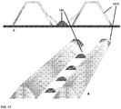
- the light source apparatus 120 may further comprise an optical channelling device (e.g. an optical fibre) to provide additional lighting effects. Additional effects may be obtained by the use of reflective surfaces, as described in relation to Figs. 15 to 18 below.
- an optical channelling device e.g. an optical fibre
- the light source When used for illumination purposes, the light source may operate at wavelength visible to the human eye (i.e. from 495-570 nm). In certain embodiments that may be mentioned herein, the light source 130 may have a dominant wavelength of 527 nm. It will be appreciated that other light sources may be used for other purposes. For example, an infra-red light source may be used in a garment to provide heat to treat an injury in a specific body part of a subject. In alternative embodiments, the light source may operate at an ultraviolet wavelength in order to provide a therapeutic or diagnostic effect. These additional uses for light sources will be discussed in more detail hereinbelow.
- the flexible and conformable light source apparatus 120 of the device 100 may further comprise at least one flexible substrate 170 (e.g. the flexible substrate is made from one or more of the group selected from polyethylene naphthalate, polyethylene terephthalate and polyimide) with at least one electrical circuit thereon, where the at least one light source 130 (depicted as two lights sources in this embodiment) is attached to the at least one flexible substrate through the at least one electrical circuit (e.g. the attachment may be by use of an isotropic conductive adhesive or by soldering) and the at least one electrical circuit is connected to the at least two conductive members 140 (e.g.
- the at least two conductive members 140 may be one or more of the group selected from a wire (e.g. silver, copper, stainless steel), a conductive yarn, a screen-printed conductive path (e.g. a conductive paste) and combinations thereof).
- the at least one electrical circuit may comprise silver and/or copper. It will be appreciated that in all aspects and embodiments mentioned herein, the flexible substrate and the electrical circuit thereon are fully encapsulated within the at least one polymer layer.
- any suitable conductive yarn may be used in the current invention, provided that there is provided an uninsulated terminal section.
- the entire conductive yarn may be uninsulated, while in other embodiments, the majority of the conductive yarn may be protected by an insulating material.
- the terminal section of the conductive yarn may be provided with an insulating material that is removed from the terminal section of the conductive yarn to provide an uninsulated conductive yarn. This is discussed in more detail in Figure 6 .
- the term "yarn" is intended to take its ordinary meaning in the art (long continuous length of interlocked fibres, suitable for use in one or more of the production of textiles, crocheting, knitting, weaving, embroidery and, more particularly sewing), though it is expanded herein to also cover the use of single filaments of a material, such as a metallic filament.
- the uninsulated conductive yarn may be a thin metal wire (e.g. a metal filament suitable for use in one or more of the production of textiles, crocheting, knitting, weaving, embroidery and, more particularly sewing), a metal yarn (i.e. interlocking metal fibers), a yarn or filament made from a conductive polymer, and a conductive composite yarn.
- a number of different kinds of conductive composite yarns exist.
- a first type of conductive composite yarn comprises a normal non-conductive yarn's fibres as a core material that is impregnated with at least one conductive material, such as a metal or a non-metallic conductive material, which latter material may be provided in part in a polymer matrix.
- a second type of conductive composite yarn comprises a normal non-conductive yarn's fibres as a core material that is then wound together with one or more filaments/fibres of a metal and/or a non-metallic conductive material.
- a third type of conductive composite yarn comprises a non-metallic conductive material, such as carbon nanotubes or graphene along with a polymeric material, wherein the non-metallic conductive material may be distributed homogeneously throughout the polymeric material to provide a conductive yarn, or the non-metallic conductive material is aligned to form a yarn, with a polymer dispersed within the spaces created in said yarn (e.g. a continuous superaligned carbon nanotube yarn as a conductive framework with polyvinyl alcohol inserted into the intertube spaces of the framework, as described in Liu et al. ACS Nano, 2010, 4 (10), pp 5827-5834 ).
- a polymer dispersed within the spaces created in said yarn e.g. a continuous superaligned carbon nanotube yarn as a conductive framework with polyvinyl alcohol inserted into the intertube spaces of the framework, as described in Liu et al. ACS Nano, 2010, 4 (10), pp 5827-5834 ).
- Metals that may be mentioned in aspects and embodiments of the invention include, but are not limited to, iron, copper, silver, gold, aluminium, brass, titanium, and platinum and alloys thereof.
- a metal alloy that may be mentioned herein is stainless steel.
- conductive yarns when more than one conductive yarn is used in embodiments of the invention, they may be made of the same material or of different materials.
- silver coated yarns, stainless steel coated yarns, copper wires, and silver wires may all be used in conjunction in certain embodiments of the invention.
- the term "electrical circuit” may relate to a printed circuit (e.g. a screen-printed circuit) or by lithographic etched circuit (e.g. a lithographically etched copper circuit).
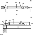
- Fig. 2A also depicts the use of an electrical interconnect 300, 400 to connect the power source 150 (e.g. a power supply unit) to the light source apparatus, such that the power source is easily detached from the garment and/or textile.
- the power source 150 e.g. a power supply unit
- second ends 142 of the conductive members 140 interface with the interconnect portion 300 attached to the garment 110.
- the majority (or all, as described below) of the wiring that is not encapsulated within the polymer layer 160 may be encapsulated, for example through the use of an additional polymeric component 180 (which may be of the same material described in respect of the polymer layer 160) to help protect the conductive members 140 from exposure to the environment.
- the exposed wires may be surrounded by an additional textile layer, so as to provide additional comfort to the wearer, while also providing electrical insulation. It will be understood that a portion of the conductive members 140 are left unencapsulated so as to enable engagement into the interconnect portion 300, though any remaining exposed wiring is covered (e.g. as described above) once the connection to the interconnection portion 300 has been established.
- the power source 150 also further comprises an interconnect portion 400 to enable transfer of power from the power source to the flexible and conformable light source apparatus 120.
- Fig. 2B depicts a further embodiment of the flexible and conformable light source apparatus 120, when attached to a garment 110, where the light source 130 faces away from the body of a wearer. It will be appreciated that such an arrangement may be useful for improving the visibility of a wearer of a garment that comprises the flexible and conformable light source apparatus 120, when the light source provides a visible light. It will also be appreciated that if the number and/or intensities and/or wavelength of the visible light is adjusted, the flexible and conformable light source apparatus may also be used to provide illumination to the wearer of the garment (e.g. cyclists and runners), such that the wearer's path is illuminated.
- the flexible and conformable light source apparatus may also be used to provide illumination to the wearer of the garment (e.g. cyclists and runners), such that the wearer's path is illuminated.
- This may be used to provide a short- to long-distance illumination and may include the path in front of the wearer, as well as illumination to the sides and back of the wearer, depending on the application in question.
- such devices in common with others discussed herein, may generate an amount of heat that leads to an increase in the surface temperature of at least the skin layer of the wearer, thereby helping to keep the wearer warm. This may be beneficial for a wearer facing inclement weather, or to a user who has an injury to a muscle and is in need of heat therapy.
- the flexible substrate 170 e.g. a PEN substrate
- the flexible substrate 170 is attached to the light source 130 by way of a silver conduction pad 190, with the light source 130 being bonded to the surface of the conduction pad 190 by an isotropic conductive adhesive.
- the silver conduction pad 190 of this embodiment is in conductive contact with the conductive member 140.
- the flexible and conformable light source apparatus 120 is encapsulated in a number of layers of encapsulating polymer (160a-d).
- a hole 110a can be cut into the fabric 110 to enhance the light emitted from the light source to the outside world (combinations of light sources covered and light sources that are exposed by holes 110a are contemplated).
- an additional polymer layer (e.g. made of the same materials previously described for polymer layer 160) may be used.
- the polymeric layer 110b is heat-bonded to the fabric 110 and the light source apparatus 120 is then heat-bonded to the polymeric layer 110b.
- a single layer of unbroken polymer may be heat-bonded, with a hole then being cut through the fabric to generate hole 110a.
- hole 110a may be generated first, followed by heat bonding two separate polymer layers 110b to either side of hole 110a.
- the hole 110a may be sealed with a different material, such as a transparent TPU or silicone.
- a combination of light sources facing away from the body is also contemplated, where some of the light sources are covered by the original material, some are exposed by holes 110a and some are exposed by holes 110a, but which holes are sealed with a different material (e.g. TPU or silicone). Further, it will be appreciated that the component layers of 120a may be inverted so that the light source 130 faces towards the wearers skin instead. In this arrangement, hole 110a may be absent.
- a different material e.g. TPU or silicone
- the flexible light source is kept as thin as possible (e.g. less than or equal to 350 ⁇ m).
- the flexible substrate 170, polymer layers 160b-d and polymer layers 110b may have a thickness of 75 ⁇ m, while polymer layer 160a may have a thickness of 160 ⁇ m.
- the flexible and conformable light source apparatus may have a thickness that is from 350 ⁇ m to 650 ⁇ m.
- first and fourth polymer layers of 75 ⁇ m thickness may be replaced with polymer layers having 150 ⁇ m thickness and/or the second and third polymer layers of 150 ⁇ m thickness may be replaced by polymer layers of 125 ⁇ m thickness).
- the flexible and conformable light source apparatus may have a bending radius of from 0.001 mm to 10 mm (e.g. such as from 0.01 mm to 1 mm, from 1 mm to 10 mm, from 2 mm to 6 mm, such as 5 mm or less).
- These arrangements may provide the light source (e.g. an LED or an OLED) with impact protection and enable the flexible and conformable light source apparatus to survive washing.
- a garment may be capable of being washed at least up to 30 times (e.g. at least up to 50 times, such as at least up to 100 times) without affecting the function of the flexible and conformable light source apparatus attached to the textile or garment. While the above arrangements are described in the context of Fig. 2B , it will be appreciated that they are generally applicable within all aspects and embodiments of the current invention.
- Fig. 2B depicts the use of a number of encapsulating layers (160a-d), which are applied individually or in a paired manner (e.g. 160a and 160b; and 160c and 160d). This arrangement may be caused by the separate introduction of the interconnect 190 and conductive member 140.
- al essential components are assembled together and are then encapsulated in a single operation.
- the encapsulation may involve a single layer of material or multiple layers. When the essential components have been assembled as a single unit before encapsulation, the encapsulation may involve more than one layer on each side of the assembly to be encapsulated. This may help to improve water resistance and also the mechanical strength of the resulting device.
- Fig. 2C depicts a flexible substrate 170 according to an embodiment of the current invention.
- Flexible substrate 170 may be made from one or more of the group selected from polyethylene naphthalate, polyethylene terephthalate and polyimide.
- An electrical circuit depicted schematically by 190 is applied to the surface (e.g. by printing the circuitry or by lithographically patterning a circuit), where the circuitry may comprise silver and/or copper and then the light source 130 (not shown) is attached to the flexible substrate (e.g. by use of an isotropic conductive adhesive or by soldering, optionally followed by underfilling of the light source.
- the flexible substrate is then die cut or patterned (e.g.
- the final form factor shown which uses a lobstered shape to engage with the first ends 141 of the two conductive members 140. It will be appreciated that any other suitable means of engaging the conductive members 140 may be used. As shown, the first ends 141 of the two conductive members 140 subsequently are placed into conductive contact with the electrical trace 190 to enable illumination of the light source.
- the flexible and conformable light source apparatus may have a thickness that is less than or equal to 1000 ⁇ m.
- the flexible and conformable light source apparatus may have a thickness of less than or equal to 750 ⁇ m, such as less than or equal to 350 ⁇ m.
- the flexible and conformable light source apparatus may have a bending radius of less than or equal to 5 mm.
- the device may be particularly comfortable to wear as part of a thin garment (e.g. a single-layer t-shirt, shirt etc), this comfort may be further improved when the flexible and conformable light source apparatus also has a bending radius of less than or equal to 5 mm.
- Thicknesses for the flexible and conformable light source apparatus include a thickness of from 400 ⁇ m to 650 ⁇ m or from 200 ⁇ m to 300 ⁇ m.
- Bending radii for the flexible and conformable light source apparatus that may be mentioned herein are from 0.001 mm to 10 mm, such as from 1 mm to 10 mm or from 2 to 5 mm.
- the total thickness of the device may be from 700 ⁇ m to 2 mm. It will be appreciated that the lower range may be particularly suitable for use in athletics wear, while the higher end of the range may be suitable for use in the manufacture of a garment/device where a thick layer of fabric may be useful (e.g. a jacket). Particular thicknesses that may be mentioned herein include, but are not limited to from 700 ⁇ m to 1,500 ⁇ m, such as from 800 ⁇ m to 1,500 ⁇ m.
- the electrical interconnect may be any suitable electrical interconnect, provided that the interconnect is capable of enabling power to be transferred from a power source to the light source(s), such that illumination of the light sources is accomplished.
- this may relate to a standard plug and socket arrangement, a releasable snap-fit connector with male and female component parts, or conductively connectable (and releasable) metal rivets.
- the electrical interconnect may contain a flexible arrangement comprising an electrical contact surface adapted to be attached to a power source with a complementary electrical contact surface.
- the electrical interconnect 300/400 may comprise: a first flexible interconnect component that is attached to the textile or fabric and to the second end of the at least two conductive members, comprising:
- Figs. 3A-D depict various views of a first flexible interconnect component 300.
- Figs. 4A-D depict various view of a second (in this case rigid) interconnect component 400 that may be used in conjunction with the flexible component 300 depicted in Figs. 3A-D .
- the electrical interconnector composed of the flexible 300 and rigid 400 parts will be described with reference to FIGS. 3 and 4 .
- the electrical connector comprises a first component 300 that is flexible which contains a first housing 310 and seven magnets 320, where the first housing 310 has a contact surface 330 and is adapted to securely house the magnets 320, so that at least part of the magnets 320 protrude from the first contact surface by from 10 ⁇ m to 500 ⁇ m (as shown most clearly in Figs. 3C and D ).
- the first component is flexible, which allows the first contact surface to adopt a range of configurations, for example, the contact surface may have a substantially planar, curved or wave-type (e.g. as shown in Fig. 3D ) configuration.
- the first housing 310 may be made from one or more of a material selected from the group consisting of leather, a synthetic leather, a rexine, silicone, a hard fabric, flexible polyurethane, polyethylene napthalene, urethane, TPU, natural rubber and synthetic rubber.
- the magnets may have a cylindrical shape, so as to present a circular shape on the contact surface 330, though any other suitable configuration is possible.
- the magnets may also be rectangular cuboid or cube-shaped, so as to present a rectangular or square shape, respectively, on the contact surface 330. Combinations of these shapes are also possible.
- the magnets 320 may simply be a shaped block of a magnetic material (e.g. ferromagnetic material or a rare-earth magnet) or they may comprise a magnet core surrounded by a non-magnet, conductive outer shell.
- the conductive outer shell may be one or more of a material selected from aluminium, copper, lead, nickel, tin, titanium, zinc, gold, silver, platinum, cobalt, lithium, tungsten, beryllium, bismuth, cerium, cadmium, niobium, indium, gallium, germanium, selenium, tantalum, tellurium, vanadium, zirconium and iron.
- the magnet core may be any ferromagnetic material (e.g. a rare earth magnet) that has been magnetised or an electromagnet (e.g. conductive coils wrapped around/through a paramagnetic material).
- Ferromagnetic materials that may be mentioned herein include iron, cobalt, nickel, alnico bismanol, chromium(IV) oxide, dysprosium, fernico, gadolinium, gallium manganese arsenide, heusler alloy, magnetite, metglas and MKM steel.
- the total surface area of the magnets 320 compared to the total surface area of the entire first contact surface 330 is approximately 7.2%.
- the total surface area of the magnets 320 compared to the total surface area of the entire first contact surface 330 may be from 4.5% to 90.0% (e.g. from 4.5% to 50.0%, from 5% to 40%, such as from 7% to 30%, such as from 8% to 25%).
- the first housing 310 has a depth substantially perpendicular to the first contact surface 330.
- each housing contains a hole for each magnet (not shown), where the hole is adapted to securely hold the magnet.
- this may be achieved by: gluing the magnets 320 to the first housing 310 with back plates that are attached to the magnets 320 and which back plates are larger than the hole; having one or more grooves in the magnets 320 that fit (e.g. snap-fit) with a corresponding projection in the first housing 310; tapering the magnets 320 and the first housing 310 in an axial direction; or tight-fitting the magnets to housing.
- the holes are substantially perpendicular to the first contact surface 330 and extend from the first contact surface to the opposite side of the housing (i.e. the holes are through holes).
- This arrangement allows the magnets to be in direct contact with a conductive material.
- the holes in the first housing may be a blind hole having at least one wall, where the at least one wall further comprises an aperture suitable for a flexible conductive member (e.g. a wire). It will be appreciated that each hole is independent and so the first housing may contain a combination of such arrangements.
- the first flexible component 300 of Figs. 3A-D also contains a rivet holes 360 and a groove 350 in the housing that are situated between the magnets 320.
- the rivet holes 360 enable the flexible component to be fixed to an object (e.g. a garment) and may positioned in any suitable part of the flexible component.
- the groove segment may be as flexible as the rest of the flexible component. However, sections of the flexible component containing grooves may be less flexible than the remainder of the flexible component. It will be appreciated that these sections retain a degree of flexibility and are not rigid.
- Fig. 5A helps to illustrate the flexible component as part of a garment or textile/fabric 110.
- the flexible component 100 comprises a number of flexible layers (510-530) that are bonded to a layer of fabric 110, which may be the body the garment by way of a polymeric layer 560 (e.g. made from a thermoplastic polyurethane) that acts as a barrier material to insulate the electrical components of the flexible component 300 from environmental factors (e.g. sweat and body fluids from the body of the wearer), while helping to insulate the wearer from the electrical current produced by the device in operation.
- the flexible component part 300 contains a flexible base layer 510 (e.g.
- the silver (or copper) layer 520 is in direct conducting contact with the magnets 320 of the first flexible component 300, as well as two or more conductive wires 140 that extend laterally from the surface of the silver layer 520.
- the magnet(s) 320 are situated in a hole through two layers of the first component 300, an electrically insulating layer 530 (e.g. made from a thermoplastic polyurethane) and the first contact surface layer 310, which may be made of any of the materials described above.
- a further layer of an insulating polymer 570 may be laid on top of it to encapsulate and protect it and the silver layer 520 from environmental factors (the encapsulating being achieved in combination with the other insulating layers 530 and 560.
- the wire 140 may be encapsulated in an insulating material over its entire length, except for the terminus, which is in conductive contact with an electrical device or sensor as described herein.
- the first flexible component may also be encased in a covering of fabric attached to the layer of fabric 550 to form a pocket suitable to house the first flexible component and the second component. This arrangement is advantageous when the second component incorporates a power supply unit.
- Fig. 5C depicts, in contrast to Fig. 5A , insulating layer 560 is not present and the magnet 320 is contained in a recess within the first contact surface 330 (e.g. see Fig. 3A and Fig. 5D ).
- the second contact portion 410 will have a magnet 420 that protrudes from the surface of the contact surface 43, such that it can magnetically connect to magnet 320.
- This may mean that the protrusion of magnet 420 has a height that matches the depth of the recess of magnet 320, although the height may be greater than the depth (e.g. from 1 to 10 ⁇ m greater). This is depicted schematically (and in cross-section) in Fig. 5D .
- Fig. 5B depicts the base layer 510 and silver (or copper) layer 520 that may be used to distribute electricity from the first interconnect component 300 to the flexible light apparatus 120 (e.g. in the embodiments of Fig. 5A or 5C ).
- the base layer and conductive layering are cut into a defined shape to enable the distribution of power through multiple conductive members 140.
- the construction and shaping of these layers may be conducted using the techniques discussed in respect of the flexible substrate 170 hereinbefore.
- the flexible connection component 300 may relate to a male snap-fit portion of an electrical interconnect that comprises a number of flexible layers (510-530) that are bonded to a layer of fabric 110, which may be the body the garment by way of a polymeric layer 560 (e.g. made from a thermoplastic polyurethane) that acts as a barrier material to insulate the electrical components of the flexible interconnection component 300 from environmental factors (e.g. sweat and body fluids from the body of the wearer), while helping to insulate the wearer from the electrical current produced by the device in operation.
- a polymeric layer 560 e.g. made from a thermoplastic polyurethane
- the flexible interconnection component 300 contains a flexible base layer 510 (e.g. made from poly(ethylene 2,6-naphthalene dicarboxylate); PEN) onto which is bonded a flexible layer of silver 520 (e.g. a screen-printed layer of silver), which provides the conductive and/or data connectivity in this embodiment.
- the silver (or copper) layer 520 is in direct conducting contact with a male snap-fit conductive member 320, that is arranged to reversibly mate with a female snap-fit conductive member (not shown), as well as two or more conductive wires 140 that extend laterally from the surface of the silver layer 520.
- the male member 320 is situated in a hole through two layers of the a flexible interconnection component 300, an electrically insulating layer 530 (e.g. made from a thermoplastic polyurethane) and a first contact surface layer 310, which may be made of any of the materials described above.
- an electrically insulating layer 530 e.g. made from a thermoplastic polyurethane
- a first contact surface layer 310 which may be made of any of the materials described above.
- the female snap-fit member is not shown, it will be appreciated that this may be housed on an interconnection component that contains additional electrical components, such as a power supply unit, and may be rigid or flexible. It will be appreciated that any suitable interconnection arrangement may be used herein.
- the primary purpose of the interconnection arrangement is to provide a coupling that enables power from a removable power supply unit to be supplied to the visibility-enhancing device of the current invention. As shown in Figs.
- the electrical connector comprises a second component 400 that is rigid which contains a second housing 410 and three magnets 420, where the second housing 410 has a contact surface 430 and is adapted to securely house the magnets 420, so that at least part of the magnets 420 protrude from the second contact surface by from 10 ⁇ m to 500 ⁇ m (as shown most clearly in Figs. 4C and D ).
- the second component 400 is rigid and provides a planar contact surface 430, and is made from a non-conductive, rigid material typically used in the art, such as, but not limited to such as plastic, wood, metals with non-conductive shielding.
- the second component may also be flexible and when it is, the second housing may be made of the same materials discussed above for the first housing.
- the second component interconnect 400 of Figs. 4A-D also contains a projection 440 that is complementary in shape (and, optionally size) to the groove 350 in the first component part of Figs. 3A-D . As shown, the projection 440 extends from the surface of the second contact surface 430.
- the magnets 420 depicted in Figs. 4A-D have a rectangular cuboid shape and are positioned to complement the magnets in the first component 300.
- the magnets 420 may be made from the same materials as magnets 320 of the first component 300 (e.g. they may also comprise a magnetic core surrounded by a conductive outer shell). Again, as for the magnets 320, the magnets 420 may also take any other shape. As shown, it is not necessary for the magnets of the first and second components to be identical in number or shape, though it is necessary for them to be positioned complimentary to each other. It is not necessary for the magnets to have approximately the same surface area to enable the interconnection to function.
- the total surface area of the magnets 420 compared to the total surface area of the entire second contact surface 430 is approximately 7.2%.
- the total surface area of the magnets 420 compared to the total surface area of the entire second contact surface 430 may be from 4.5 % to 50.0% (e.g. from 5% to 40%, such as from 7% to 30%, such as from 8% to 25%).
- the holes (not explicitly shown) that securely hold the magnets 420 have essentially the same configuration as described for the holes in the first housing (e.g. the holes may be through-holes or blind holes having at least one wall, where the at least one wall further comprises an aperture suitable for a flexible conductive member).
- the magnets 320, 420 are complimentarily positioned in the first 310 and second 410 housings, respectively, to enable coupling of the first and second contact surfaces 330, 430 through magnetic attraction of the magnets 320, 420.
- the magnets 320, 420 have complementary polarities, so as to ensure magnetic attraction.
- the magnets 320 have a north polarity, with the magnets 420 having a south polarity.
- one of the magnets 320 may have a north polarity, while the other has a south polarity, with the magnets 420 on the second component 400 having polarity that complements the magnet that it is intended to connect with.
- the magnets 320, 420 enable the coupling of the first 300 and second 400 components. Further, when the first component is attached to a first device and the second component is attached to a second device, the magnets 320, 420 are also responsible for conducting electricity and/or signalling data from the second device to the first device, or, in the case of data, vice versa.
- the ability to conduct electricity and/or signalling data through the magnetic parts of the devices of the current invention removes the need for additional male and female components to provide conductive functionality and therefore reduces the chances of the device being damaged in use. Further, this arrangement also removes the need to have additional moving components that increase the size and complexity of the device (e.g. springs to enable better connection of the male and female components).
- the device depicted in Figs. 3A-D and Figs. 4A-D contains magnets 320, 420 that are held in position by a through-hole in the respective housing to which they are attached.
- This arrangement is particularly suitable for direct attachment of the magnet to a printed circuit board (which is flexible) or to a wire, said conductive elements being in conductive contact with the respective devices.
- Any suitable combination of a printed circuit board and wire is contemplated by the current invention.
- the blind holes comprise at least one wall that has an aperture suitable to enable a flexible conductive conduit (e.g. a wire) to come into direct contact with the magnet 320, 420 and so enable the conduction of electricity/data.
- any suitable combination of through- and blind-holes are explicitly contemplated.
- a major advantage associated with the flexible connector described herein is that one does not have to obtain a precise alignment of the component parts before attempting to connect the parts together, as the magnets 320, 420 have the ability to enable self-alignment of the component parts when brought into magnetic proximity to one another (e.g. the components can be up to 5 mm out of alignment with one another). This reduces the chances of the connection device being damaged.
- a related advantage is that, as one of the components is flexible, said components have the freedom to move and the magnets may respond by moving slightly to retain the self-alignment and electrical/signalling conductivity.
- connection presents a flat surface and is much thinner than conventional connectors, which require much larger designs to accommodate the male and female components used for electrical conductivity.
- Figs. 6A and 6B depict a rigid component according to Figs. 4A-D and a flexible component similar to the component depicted in Figs. 3A-D , respectively.
- the rigid component 410 has a first contact surface 430, a projection 440 and magnets 420 that are arranged to be complementary to the magnets 320, groove 350 and first contact surface 330 of the flexible component 310 depicted in Fig. 6B.
- Fig. 6C depicts the joining of said flexible 300 and rigid 400 components schematically and shows that the smaller and more numerous magnets 320 of the first component 300 are arranged to bind to the larger, but less numerous magnets 420 of the second component 400 and the groove 350 holds the projection 440.
- the power supply unit may be any suitable power supply unit that can connect to the lighting module attached to the textile/fabric or garment.
- the power supply unit may comprise a battery and a DC-DC boost converter.
- the power supply unit may further comprise a switching module adapted to control a number of lighting modes of the light source.
- the power supply unit may further comprise an ambient light detector adapted to control the brightness of the light source based upon the ambient light conditions (e.g. wherein one or more of the lighting modes of the switching module is controlled fully or in part by the ambient light detector).
- the brightness of the device may also be controlled by:
- the mode selector may make use of none, one or a combination of the above sensors and the light detector (e.g. light dependant resistor) to control the brightness of the light sources.
- the light detector e.g. light dependant resistor
- Fig. 7A depicts a cross-section of a power supply unit 150 according to the current invention, wherein at least some of the features described above are depicted, along with additional optional features.
- the power supply unit 150 has a housing that encloses a battery 720 (e.g. a rechargeable Li-ion battery) and a switch 730 and a printed circuit board (PCB) 740 that houses the relevant electronics to operate the various component parts of the power supply unit depicted and described above.
- the housing contains the second interconnect member 400, with the projection 440 visible.
- Fig. 7A depicts a USB port 750, which may be used to charge the battery 720, when said battery is a rechargeable battery.
- a USB port may be absent, with the second interconnect 400 enabling a rechargeable battery to be charged or the rechargeable battery may be adapted so that it can be charged using wireless power.
- Fig. 7B shows the same power supply unit from the bottom face, that is the face housing the second interconnect unit, showing magnets 420 on either side of groove 440 and the USB port 750.
- Figs. 8 to 11 describe the arrangement of an embodiment of the entire integrated device 100 as and how the device 100 may be used.
- Fig. 8 depicts the device 100 as an electronic circuit schematic.
- the device 100 requires the presence of a detachable power module 150 that is connected to the wiring of the lighting module 810 by an interconnect 300/400.
- the battery module may contain a battery 720 (e.g. a rechargeable Li-ion battery operating at around 3.7 Volts) and a DC-DC Boost Converter 820 (e.g. to step-up the voltage from 3.7 Volts to 24 Volts).
- the lighting module contains several lighting source strips integrated into a textile (not shown) containing the following either LEDs or OLEDs that are encapsulated in a flexible polymer (not shown), as discussed in more detail hereinafter.
- the battery module may further contain all of the power and driving electronics necessary to operate the device, as illustrated in Figs. 9 and 10 .
- a current-limiting resistor may be added.
- Fig. 9 depicts a full system 900 according to the current invention in schematic form.
- the power supply unit 901 contains a USB connector 902 a power module 903 (which contains a battery, a DC-DC converter, switching module, automatic light sensor and electronics to drive these components on a printed circuit board) and an interconnect 904 to contact the interconnector (906; i.e. contact pads) on a garment 905 (though this may be any other object made from a fabric or a textile).
- the garment 905 contains an interconnect 906 to interface with the interconnect 904 of the power supply unit (e.g.
- a conductive yarn 908 this may also be a wire or a printed conductive path (e.g. a conductive paste)
- lighting strips 909 comprise a circuit module interconnection 910 and a lighting module (e.g. a LED).
- Fig. 10 more clearly depicts the electrical circuits used within the power module of an embodiment of the invention, though not shown in connection, whereas Fig. 11 describes the physical system architecture and interaction of these components.
- the Power module can be separated into four entities by their main function: charging 1101, mode selector 1102, DC-DC converter 1103 and detachable interconnection 1104.
- the main function of the charging part of the power module 1100 is charging the battery 1105 of the lighting system by means of a USB connector 1106 and providing the user with feedback by means of a charging indicator LED 1107. While the device depicted here uses a separate USB connector 1106 to achieve the charging, it is contemplated that the interconnect system, as described in more detail below can also achieve the same effect. In addition, it is contemplated that the power module could also make use of swappable batteries (e.g. alkaline batteries).
- the power module 1100 When the power module 1100 is plugged into an USB wall-mount adaptor or USB port, power will be drained from the attached power source in order to charge the internal battery 1105 of the power module.
- the charging interface will regulate the current and voltage levels to charge the battery 1105 (e.g. any rechargeable battery, such as a Li poly battery and a Li-ion battery).
- the power module 1100 will monitor the power level of the battery to ensure proper charging and the charging interface 1108 will also drive an indicator LED providing the user with visual feedback about the charging status of the battery (e.g. red while charging, green/off when full).
- a voltage comparator 1109 is implemented into the power module to warn the user that the battery only has 20% charge left by lighting up a red LED 1111.
- the battery module may also contain a mode selector 1102 that is responsible for setting the desired lighting mode of the lighting apparatus.
- the mode selector 1102 comprises a tactile switch 1112, light mode selector circuitry 1113, current regulating resistors for 50% (1114) and 100% (1115) brightness settings, a light dependent resistor 1116 and a pulse generator 1117 circuit. These components can be used to select any one of the following modes, in the order presented.
- the system will be on the "Off state”. This means that no light will be produced by the system.
- the selector will move forward one mode per click.
- An ambient light sensor in the form of an LDR is used in the last 2 modes to allow the system to respond to the environmental lighting conditions.
- a pulse generator may be incorporated to generate a varying breathing-like animation that can be used in the last mode.
- the mode selector selects one or more of the sub-systems (as required) and electrically connects them to the DC-DC converter 1103.
- the main function of the DC-DC converter 1103 is to scale the voltage level of the battery up to a higher potential in order to drive the lighting modules. This is needed to compensate for voltage drops over the circuit on the garment that connects the lighting modules to the power module.
- the DC-DC converter may be set to the required current based on input from the mode selector.
- a voltage comparator 1109 is included in the power module to measure the battery's charge level. When the battery charge gets below 20%, a red LED will light up 1111, notifying the user that the system should be charged again.
- a re-attachable interconnection 1104 is the bridge between the power module and the garment. It makes an electrical interconnection, allowing power to flow from the power module's DC-DC converter 1103 to interconnect component attached to the power module. As discussed in more detail hereinbefore, the interconnect may be made using magnetic interconnection components on the power module and the garment, which allowed the connection to be made and broken in easily. This allows the power module and garment to be bonded for use and separated for charging and washing with little difficulty.
- the brightness of the device may also be controlled by:
- the mode selector may make use of none, one or a combination of the above sensors and the light detector (e.g. light dependant resistor) to control the brightness of the light sources.
- the light detector e.g. light dependant resistor
- Li-Fi Light Fidelity
- Wi-Fi is a bidirectional, high speed and fully networked wireless communication technology similar to Wi-Fi.
- Li-Fi is a subset of optical wireless communications and can be a complement to RF communication (Wi-Fi or Cellular network), or a replacement in contexts of data broadcasting. It is so far measured to be about 100 times faster than Wi-Fi, reaching speeds of 224 gigabits per second. It is wireless and uses visible light communication or infra-red and near ultraviolet (instead of radio frequency waves) spectrum, part of optical wireless communications technology, which carries much more information, and has been proposed as a solution to the RF-bandwidth limitations.
- the device may further comprise a sensor and/or control system that can make use of the light sources within the device to transmit data gathered by a sensor (e.g. an accelerometer, 9-axis sensor or any other compatible data gathering device) to a receiver in a nearby Li-Fi enabled device, such as a cellular telephone (i.e. a smart telephone), a computer or directly onto a server using an internet connection established by Li-Fi.
- a sensor e.g. an accelerometer, 9-axis sensor or any other compatible data gathering device
- Li-Fi enabled device such as a cellular telephone (i.e. a smart telephone), a computer or directly onto a server using an internet connection established by Li-Fi.
- the sensor/controller is able to adjust the intensity (i.e. brightness) of the light generates by the light source(s) at high speed, while maintaining illumination, though invisible light may be used instead (as mentioned above).
- the garment or textile/fabric component can be split into two main sub-systems: the lighting system and the other half of the re-attachable interconnection.
- the lighting system can contain three lighting modules, the modules provide visual lighting at several locations on the garment or textile/fabric.
- Each lighting module is a strip with several light emitters 1205 (in the embodiment shown, LEDs or OLEDs).
- the re-attachable interconnection 1201 is the bridge between the power module and the garment.
- the interconnection that forms part of the lighting module makes an electrical interconnection with the corresponding component on the power module, allowing power to flow from the connector pads to the individual lighting modules to light them.
- the connection can be made and broken easily, allowing the power module and garment (or textile/fabric) to be bonded for use and separated for charging and washing.
- the textile or fabric may be in the form of a garment or other object made from such materials (e.g. a bag).
- the garment may be any wearable object, such as shorts, socks, T-shirts, trousers, leggings, shirts, caps, footwear (e.g. shoes, boots, training shoes etc) and accessories (e.g. head bands, arm warmers, wristbands etc).
- Fig. 12 depicts the lighting module of an embodiment of the current invention.
- the lighting module 1200 comprises landing pads 1201 for the conductive yarn on a textile to interface with the electrical components on the lighting module, which landing pads are connected (e.g. by electrical traces) to one or more current limiting resistors for LEDs (1202-1204) and multiple LEDs (1205).
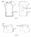
- Figs. 13A and 13B disclose a T-shirt 1100, shorts 1200 and Fig. 14 depicts a long-sleeved shirt 1300 according to embodiments of the current invention, depicting an integrated lighting system in a garment.
- lights 1120 which may be one or more of light emitting diodes (LEDs), organic light emitting diodes or an electroluminescent material, that are attached to the front, back and/or sides of the garment to provide illumination.
- the lights are connected by some form of wiring (not shown) to a power supply unit 1130, which provides power and may perform additional functions as discussed in more detail below.
- the garments may also contain passive reflective strips 1140 to reflect light from the beam of a vehicle and may help make a wearer more visible in low-light conditions.
- Figs. 13 and 14 relate to sports garments with unobtrusive integrated electronics in accordance with the embodiments of the invention disclosed hereinbefore.
- one or more flexible lighting apparatus 120 are embedded into the garment, drastically increasing the visibility of the wearer while performing running exercises, especially in a dim environment.
- the one or more flexible lighting apparatus 120 contain light engine elements 130 (LED, OLED) according to a pre-defined pattern, color and shape.
- a separate electronics module can be attached and detached from the garment, which incorporates the driving electronics, rechargeable battery and a switch which is the main interface for the user to select the desired lighting mode (on and off / breathing animation / set brightness / automatic brightness).
- the current invention may be integrated into sportswear
- embodiments of the current invention may also relate to the use of the integrated lighting system in any fabric or textile.
- the lighting system may be integrated into any type of garment, such as, but not limited to, accessories (such as head bands, arm warmers, wristbands, etc), uniforms for rescue workers, night patrol etc, construction or safety wear, winter sports, mountaineering clothing and gear, caps and footwear.
- the lighting system may also be integrated into non-wearable devices made of fabrics or textiles, such as a bag.
- the embodiments depicted in Figs. 13 and 14 are described above as providing an illumination purpose, similar garments may be designed to achieve different effects on the human body (or to mix-and-match such effects).
- the light source instead of using light source that is faced away from the body (i.e. for the purposes of illumination or other effects), the light source may instead be directed towards the body instead.
- the light source may be a LED or an OLED (or other light source) that is adapted to provide light at a wavelength that may increase the energy levels of the human body, such as increasing the energy generation of mitochondria in the cells of the muscles, which may aid the recovery of sportsmen/athletes to recover faster from pain and/or physiological fatigue to a normal state.
- Similar systems may be used to aid subjects that are suffering from pain (such as chronic back pain).
- various light sources may be directed towards the skin of the wearer and may be positioned in areas that are desired for treatment (e.g. the legs, arms or back of a wearer). While any suitable light source may be used, it is noted that visible red and near infra-red light sources may be particularly suitable for this application (see for example Pain Res Manag. 2006 Autumn; 11(3): 193-196 ).
- the inverted arrangement of the light sources discussed herein, where light is directed towards the body may additionally or alternatively be particularly useful in providing a source of heat to the skin, thereby causing the wearer to feel warmer, which may of particular importance in cool/inclement weather. While any light source may be used to accomplish this, particular embodiments of the invention herein may mention the use of infra-red light sources in this application.
- a further use of the device described herein may be to effect cooling of the human body.
- the light source may be arranged to use heat from the skin of a wearer as the energy source, resulting in a cooling of the wearer's skin. This may be accomplished by the use of specially adapted light sources that harvest the heat directly (through the polymer layers of the device) or by the use of body energy harvesting pads in place of a battery (e.g. said pads being made of a material that uses the Peltier effect to generate electricity.
- the garment may be adapted for use as a light-embedded near infra-red spectroscopy + pulse oximetry device, which can be used to measure relative haemoglobin levels in the human body and hence VO 2 max.
- the light sources may be near infra-red light sources (e.g. LEDs or OLEDs) and the device may further contain detection systems that may also be incorporated into the flexible and conformable light source apparatus that is described hereinbefore.
- Such an embodiment of the invention may be used to measure the fatigue level of the human body when worn by sportsmen/women, or for the provision of a medical diagnosis in other subjects.
- this embodiment of the current invention can be used as a tool for designing training programs that enhance and maintain maximum muscle efficiency and strength. Additionally, such measurements may be useful during standard training to help attain peak performance, or during training while recovering from an injury to a muscle. Data from such a device would enhance this active and growing field of sport science and performance. It is also noted that such a device may have medical uses, such as monitoring the oxygenation of a baby's blood. Examples of the kinds of systems that may be adapted for use in the current invention are provided in J Clin Monit Comput.
- a light source directed towards the skin in the current invention include garments that may be beneficial for the detection and treatment of cancer. Detection can be accomplished by using specific wavelengths of the visible or broader light spectrum that can be reflected or absorbed by particular cancer cell types such that the variation between the total light input versus output can be measured to see amount of reflection or absorption and can therefore detect changes in cells, leading to the detection of cancer.
- the light source may be a UV light source that is used in photodynamic therapy.
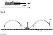
- Fig. 15 schematically depicts an encapsulated light source 120 (the light source being encapsulated in a polymer 160 as described before), where a reflective layer 110c is placed between the fabric 110 and the light source 140. As shown, the light source 120 is arranged to emit light at an angle relative to the reflective layer, as illustrated by the arrow in said figure.
- the reflective layer may be placed in alternative arrangements (e.g. between the light source and the skin in a garment where the light source is directed towards the skin), which may generate a more diffuse light.
- the reflective layer may be coloured so as to change the colour of the light perceived by an observer, and/or it may be patterned to produce pattern/shape made from the light.
- Fig. 16A depicts a further embodiment of the current invention, where the lighting apparatus is arranged on the surface of a textile or fabric and is positioned such that the light sources 140 project their light diagonally to said surface onto a reflective dome 1510.
- the light sources may be arranged to provide a linear or cross-shaped projection of light onto a plurality of reflective domes 1510 to generate different lighting effect.
- the reflective domes may be patterned and/or may be coloured.
- Figs. 17a and 17b depict a further arrangement of the concept described and depicted in Fig. 16 , where trapeziod-shaped reflective surface 1510 is used instead of the dome-shapes shown in Fig. 16 .
- Figs. 18a and 18b depict another possible arrangement of the concept described and depicted in Fig. 16 , where the lighting apparatus is placed within a concave reflective member 1510.
- garments and textiles of the current invention may be capable of being washed at least up to 30 times (e.g. at least up to 50 times, such as at least up to 100 times) without affecting the function of the flexible and conformable light source apparatus attached to the textile or garment.
Landscapes
- Engineering & Computer Science (AREA)
- General Engineering & Computer Science (AREA)
- Textile Engineering (AREA)
- Mechanical Engineering (AREA)
- Physical Education & Sports Medicine (AREA)
- Health & Medical Sciences (AREA)
- General Health & Medical Sciences (AREA)
- Power Engineering (AREA)
- Microelectronics & Electronic Packaging (AREA)
- Professional, Industrial, Or Sporting Protective Garments (AREA)
- Structure Of Printed Boards (AREA)
- Purses, Travelling Bags, Baskets, Or Suitcases (AREA)
- Arrangement Of Elements, Cooling, Sealing, Or The Like Of Lighting Devices (AREA)
- Footwear And Its Accessory, Manufacturing Method And Apparatuses (AREA)
- Optical Elements Other Than Lenses (AREA)
- Fastening Of Light Sources Or Lamp Holders (AREA)
- Electroluminescent Light Sources (AREA)
Applications Claiming Priority (2)
| Application Number | Priority Date | Filing Date | Title |
|---|---|---|---|
| GBGB1501297.4A GB201501297D0 (en) | 2015-01-27 | 2015-01-27 | Device |
| PCT/SG2015/050514 WO2016122399A1 (en) | 2015-01-27 | 2015-12-30 | Textile or fabric with attached flexible and conformable light source apparatus |
Publications (2)
| Publication Number | Publication Date |
|---|---|
| EP3250063A1 EP3250063A1 (en) | 2017-12-06 |
| EP3250063B1 true EP3250063B1 (en) | 2021-10-13 |
Family
ID=52673960
Family Applications (2)
| Application Number | Title | Priority Date | Filing Date |
|---|---|---|---|
| EP15823838.6A Active EP3250063B1 (en) | 2015-01-27 | 2015-12-30 | Textile or fabric with attached flexible and conformable light source apparatus |
| EP15823839.4A Active EP3250065B1 (en) | 2015-01-27 | 2015-12-30 | Visibility-enhancing device |
Family Applications After (1)
| Application Number | Title | Priority Date | Filing Date |
|---|---|---|---|
| EP15823839.4A Active EP3250065B1 (en) | 2015-01-27 | 2015-12-30 | Visibility-enhancing device |
Country Status (7)
| Country | Link |
|---|---|
| US (2) | US10295169B2 (enExample) |
| EP (2) | EP3250063B1 (enExample) |
| JP (2) | JP6758303B2 (enExample) |
| KR (2) | KR102477577B1 (enExample) |
| CN (2) | CN107743366A (enExample) |
| GB (1) | GB201501297D0 (enExample) |
| WO (2) | WO2016122399A1 (enExample) |
Families Citing this family (30)
| Publication number | Priority date | Publication date | Assignee | Title |
|---|---|---|---|---|
| WO2016081764A1 (en) | 2014-11-19 | 2016-05-26 | Nike Innovate C.V. | Athletic band with removable module |
| US10602932B2 (en) | 2015-12-16 | 2020-03-31 | Siren Care, Inc. | System and method for detecting inflammation in a foot |
| JP6771951B2 (ja) * | 2016-05-26 | 2020-10-21 | トヨタ紡織株式会社 | 織物、意匠織物の製造方法及び内装材の製造方法 |
| EP4420549A3 (en) | 2016-06-30 | 2024-09-18 | Nike Innovate C.V. | Apparel item with integrated lighting system |
| US10509186B2 (en) | 2016-07-28 | 2019-12-17 | Massachusetts Institute Of Technology | Thermally-drawn fiber including devices |
| FR3065131B1 (fr) * | 2017-04-06 | 2021-01-08 | Lucibel Sa | Luminaire connectable as un reseau de telecommunication |
| US11239914B2 (en) | 2016-09-13 | 2022-02-01 | Lucibel | Light fixture that can be connected to a telecommunication network |
| WO2018094276A1 (en) | 2016-11-18 | 2018-05-24 | Massachusetts Institute Of Technology | Multimaterial 3d-printing with functional fiber |
| FR3060042B1 (fr) * | 2016-12-08 | 2021-02-26 | Saint Gobain Ecophon Ab | Panneau de plafond acoustique et eclairant |
| CN121533569A (zh) | 2017-04-12 | 2026-02-17 | 耐克创新有限合伙公司 | 具有可拆卸模块的可穿戴物品 |
| EP3610350A1 (en) * | 2017-04-12 | 2020-02-19 | Nike Innovate C.V. | Wearable article with removable module |
| US10854052B2 (en) * | 2017-09-25 | 2020-12-01 | Hubbell Incorporated | Lighting fixture having an environmental detection system |
| CN108224136A (zh) * | 2018-01-31 | 2018-06-29 | 惠东县永恒电子有限公司 | 三线灯串及其制造方法 |
| JP6989403B2 (ja) * | 2018-02-12 | 2022-01-05 | セーレン株式会社 | 発光部材 |
| US20210069525A1 (en) * | 2018-05-07 | 2021-03-11 | Dmc Limited L.C. | Photobiomodulation wearable for performance enhancement |
| CA3101521A1 (en) * | 2018-05-25 | 2019-11-28 | Timothy POLANOWSKI | Method for manufacturing illuminated athletic wear |
| KR102009346B1 (ko) * | 2018-08-14 | 2019-08-12 | (주)현대포멕스 | 접을 수 있는 회로선과 led가 구비된 조명장치 및 이의 제조방법 |
| CN111254711A (zh) * | 2018-12-03 | 2020-06-09 | 东华镜月(苏州)纺织技术研究有限公司 | 一种防水传感织物 |
| WO2020118696A1 (en) * | 2018-12-14 | 2020-06-18 | Siren Care, Inc. | Method for registration and activation of temperature-sensing garments |
| KR102235091B1 (ko) * | 2019-02-21 | 2021-04-02 | 주식회사 에스디아이컴퍼니 | 원단 |
| KR20210015431A (ko) * | 2019-08-02 | 2021-02-10 | 김남균 | 비뇨생식기 기능 증진용 기능성 레깅스 |
| CN111068180A (zh) * | 2019-12-05 | 2020-04-28 | 北京小米移动软件有限公司 | 光疗眼镜和眼镜盒 |
| US12141680B2 (en) | 2019-12-30 | 2024-11-12 | Massachusetts Institute Of Technology | Fiber and fabric computers |
| US20210285633A1 (en) * | 2020-03-12 | 2021-09-16 | Arash Esmailzadeh | Wearable uv light devices |
| ES2829383B2 (es) * | 2020-12-21 | 2021-10-13 | Asociacion De Investig De La Industria Textil Aitex | Dispositivo electronico para su bordado a un textil |
| CN113558321A (zh) * | 2021-07-29 | 2021-10-29 | 广州外国语学校 | 无感知多功能智能校服 |
| TWI774499B (zh) * | 2021-08-02 | 2022-08-11 | 楊兆琳 | 抗菌染料組成物 |
| US12305843B2 (en) * | 2021-08-19 | 2025-05-20 | Signify Holding, B.V. | Lighting device having a lens plate |
| FR3140530A1 (fr) * | 2022-10-10 | 2024-04-12 | Tecmoled | Dispositif de mesure d’oxymétrie |
| US20240306759A1 (en) * | 2023-03-17 | 2024-09-19 | Fang Huang | Illuminant shoe |
Family Cites Families (50)
| Publication number | Priority date | Publication date | Assignee | Title |
|---|---|---|---|---|
| US4602191A (en) | 1984-07-23 | 1986-07-22 | Xavier Davila | Jacket with programmable lights |
| US4774434A (en) | 1986-08-13 | 1988-09-27 | Innovative Products, Inc. | Lighted display including led's mounted on a flexible circuit board |
| US4924362A (en) * | 1986-08-15 | 1990-05-08 | Alliko Unlimited Corporation | Illuminated article and waterproof illuminated harness |
| US5128843A (en) | 1991-05-13 | 1992-07-07 | Guritz Steven P W | Multipurpose optical display for articulating surfaces |
| US5455749A (en) * | 1993-05-28 | 1995-10-03 | Ferber; Andrew R. | Light, audio and current related assemblies, attachments and devices with conductive compositions |
| WO1996016291A1 (en) | 1994-11-17 | 1996-05-30 | Chien Tseng Lu | Backpack or waistpack e.l. lighting arrangement |
| JPH11339501A (ja) * | 1998-05-27 | 1999-12-10 | Ebac:Kk | 発光ファイバの取付具、発光ファイバを用いた発光体及び身体装着具 |
| US20010004808A1 (en) * | 1998-11-23 | 2001-06-28 | Hurwitz Marni M. | Safety and sports equipment, apparel and accessories using electroluminescent fibers for illumination |
| US6517214B1 (en) * | 1998-11-25 | 2003-02-11 | Kenneth C. Mitchell, Jr. | Lighted safety hunting and outdoor activity vest |
| DE60223238T2 (de) | 2001-03-22 | 2008-08-14 | Lumimove, Inc. | Beleuchtetes anzeigesystem und prozess |
| US7592276B2 (en) | 2002-05-10 | 2009-09-22 | Sarnoff Corporation | Woven electronic textile, yarn and article |
| GB2396252A (en) | 2002-10-01 | 2004-06-16 | Steven Leftly | Textile light system |
| FR2854480A1 (fr) * | 2003-04-29 | 2004-11-05 | France Telecom | Afficheur souple |
| US7374315B2 (en) * | 2004-10-15 | 2008-05-20 | Joshua Dorsey | Lighting device |
| US7543956B2 (en) * | 2005-02-28 | 2009-06-09 | Philips Solid-State Lighting Solutions, Inc. | Configurations and methods for embedding electronics or light emitters in manufactured materials |
| US20070053179A1 (en) * | 2005-09-08 | 2007-03-08 | Pang Slew I | Low profile light source utilizing a flexible circuit carrier |
| US7278758B2 (en) | 2005-09-13 | 2007-10-09 | E.S. Originals, Inc. | Motion-responsive illuminated garment |
| JP2007314925A (ja) * | 2006-04-27 | 2007-12-06 | Hideo Hirose | 電子繊維又は電子糸及びこれを用いた繊維製品 |
| US8157402B2 (en) * | 2006-05-08 | 2012-04-17 | Barseventy, Inc. | Illuminated helmet with programmable lamps and proximity sensor |
| WO2007141726A1 (en) | 2006-06-08 | 2007-12-13 | Koninklijke Philips Electronics N.V. | Textile product and method of manufacturing of such textile product |
| US20080089056A1 (en) * | 2006-10-06 | 2008-04-17 | Ronald Grosjean | Illuminated Apparel |
| US20100065873A1 (en) | 2007-03-29 | 2010-03-18 | Koninklijke Philips Electronics N.V. | Light-emitting device comprising an elastomeric layer |
| WO2009075550A2 (en) | 2007-12-12 | 2009-06-18 | Kolon Glotech, Inc | Electroluminescent fabric embedding illuminated fabric display |
| TW200927005A (en) | 2007-12-24 | 2009-07-01 | Yun-You Tsai | Personal appliance with cold light board |
| US20090201672A1 (en) | 2008-02-07 | 2009-08-13 | Ching-Hui Lee | Light-emitting clothes |
| US7857477B2 (en) * | 2008-04-03 | 2010-12-28 | Bbc Internatinoal Llc | Article of clothing with washable light module |
| KR20090117210A (ko) * | 2008-05-09 | 2009-11-12 | 황삼영 | 발광장치가 구비된 의류 |
| US7758200B2 (en) * | 2008-08-18 | 2010-07-20 | Wei-Jei Tuan | Responsive led module unit |
| DE102008054288A1 (de) * | 2008-11-03 | 2010-05-06 | Osram Gesellschaft mit beschränkter Haftung | Verfahren zum Herstellen eines flexiblen Leuchtbands |
| WO2010104706A2 (en) | 2009-03-12 | 2010-09-16 | 3M Innovative Properties Company | Garment with a retroreflective and electroluminescent article |
| WO2011027250A1 (en) | 2009-09-03 | 2011-03-10 | Koninklijke Philips Electronics N.V. | Light-emitting electronic textile with improved light diffusion |
| JP2011096901A (ja) * | 2009-10-30 | 2011-05-12 | Kitagawa Ind Co Ltd | フレキシブルledモジュール及び単体ledモジュール |
| TWM388328U (en) * | 2010-02-12 | 2010-09-11 | ming-xiang Ye | Strain light-emitting and heating structure having a battery |
| US20110199779A1 (en) * | 2010-02-12 | 2011-08-18 | Wu-I Chu | Luminous costume structure |
| TWM384453U (en) * | 2010-03-02 | 2010-07-11 | Winharbor Technology Co Ltd | Pull-resistant illuminating/heat generating structure capable of being charged in wireless manner |
| US20110235311A1 (en) | 2010-03-25 | 2011-09-29 | LEDwear Limited | Bi-directional led safety wear |
| CN102834856A (zh) * | 2010-04-16 | 2012-12-19 | 皇家飞利浦电子股份有限公司 | 具有照明功能的织物产品及其生产方法 |
| EP2579737A2 (en) * | 2010-06-08 | 2013-04-17 | Fhoss Technology Limited | Electroluminescent light assembly |
| US20120099298A1 (en) | 2010-10-20 | 2012-04-26 | Ledstore International Corporation | Light-emitting clothing structure |
| KR101035442B1 (ko) * | 2010-12-03 | 2011-05-18 | 윤선애 | 플렉시블 led 기판이 장착된 안전의류 |
| US20130077289A1 (en) * | 2011-09-22 | 2013-03-28 | Saucony, Inc. | Clothing Lighting System |
| CN104081545A (zh) | 2011-12-01 | 2014-10-01 | 夸克星有限责任公司 | 固态照明装置及其制造方法 |
| US20130250603A1 (en) * | 2012-03-21 | 2013-09-26 | Joanel Inc. | Illumination method and system for a bag |
| JP6075969B2 (ja) | 2012-05-22 | 2017-02-08 | 株式会社小糸製作所 | 車両用前照灯 |
| KR20130131848A (ko) * | 2012-05-25 | 2013-12-04 | 윤선애 | 전도사를 이용한 비기판형의 안전의류용 led 발광장치 및 이를 적용한 안전의류 |
| US9243797B2 (en) * | 2012-06-30 | 2016-01-26 | Quanns Wanlap Leung | Wearing apparel with LED light module |
| US8919982B2 (en) * | 2013-05-24 | 2014-12-30 | Gabriel Pulido, JR. | Lighting system for clothing |
| US9119264B2 (en) * | 2013-05-24 | 2015-08-25 | Gabriel Pulido, JR. | Lighting system |
| CN203322810U (zh) | 2013-06-21 | 2013-12-04 | 怀集县正华电器有限公司 | 一种新型led灯管 |
| US9557049B1 (en) * | 2014-05-12 | 2017-01-31 | Carmen Rapisarda | Washable lighted garment with light effect material |
-
2015
- 2015-01-27 GB GBGB1501297.4A patent/GB201501297D0/en not_active Ceased
- 2015-12-30 JP JP2017540635A patent/JP6758303B2/ja not_active Expired - Fee Related
- 2015-12-30 KR KR1020177023960A patent/KR102477577B1/ko active Active
- 2015-12-30 WO PCT/SG2015/050514 patent/WO2016122399A1/en not_active Ceased
- 2015-12-30 WO PCT/SG2015/050515 patent/WO2016122400A1/en not_active Ceased
- 2015-12-30 US US15/546,610 patent/US10295169B2/en active Active
- 2015-12-30 EP EP15823838.6A patent/EP3250063B1/en active Active
- 2015-12-30 JP JP2017540634A patent/JP6758302B2/ja not_active Expired - Fee Related
- 2015-12-30 KR KR1020177023959A patent/KR102494606B1/ko active Active
- 2015-12-30 CN CN201580078303.8A patent/CN107743366A/zh active Pending
- 2015-12-30 CN CN201580078283.4A patent/CN107771040A/zh active Pending
- 2015-12-30 EP EP15823839.4A patent/EP3250065B1/en active Active
- 2015-12-30 US US15/546,501 patent/US11015799B2/en not_active Expired - Fee Related
Non-Patent Citations (1)
| Title |
|---|
| None * |
Also Published As
| Publication number | Publication date |
|---|---|
| JP2018513522A (ja) | 2018-05-24 |
| US20180023801A1 (en) | 2018-01-25 |
| EP3250065B1 (en) | 2021-06-09 |
| CN107743366A (zh) | 2018-02-27 |
| EP3250065A1 (en) | 2017-12-06 |
| JP6758302B2 (ja) | 2020-09-23 |
| GB201501297D0 (en) | 2015-03-11 |
| KR102477577B1 (ko) | 2022-12-14 |
| US11015799B2 (en) | 2021-05-25 |
| WO2016122400A1 (en) | 2016-08-04 |
| US20180017248A1 (en) | 2018-01-18 |
| KR20180002595A (ko) | 2018-01-08 |
| WO2016122399A1 (en) | 2016-08-04 |
| JP6758303B2 (ja) | 2020-09-23 |
| US10295169B2 (en) | 2019-05-21 |
| EP3250063A1 (en) | 2017-12-06 |
| JP2018508097A (ja) | 2018-03-22 |
| CN107771040A (zh) | 2018-03-06 |
| KR102494606B1 (ko) | 2023-02-03 |
| KR20180004704A (ko) | 2018-01-12 |
Similar Documents
| Publication | Publication Date | Title |
|---|---|---|
| US11015799B2 (en) | Textile or fabric with attached flexible and conformable light source apparatus | |
| US5032705A (en) | Electrically heated garment | |
| EP3387930B1 (en) | Fabric device | |
| US11986027B2 (en) | Electronic garment with haptic feedback | |
| CN204207739U (zh) | 一种无线心电监护衣 | |
| KR101035442B1 (ko) | 플렉시블 led 기판이 장착된 안전의류 | |
| US20130215604A1 (en) | Light emitting ribbon | |
| KR102222493B1 (ko) | 섬유제품용 발광 디바이스 모듈 | |
| KR101619514B1 (ko) | 스위칭 기능을 갖는 지퍼 및 이를 이용한 결합체 | |
| Park et al. | Designing and fabricating of the high-visibility smart safety clothing | |
| CN211794351U (zh) | 一种电加热袜 | |
| Dias | Electronically active textiles | |
| KR20130131848A (ko) | 전도사를 이용한 비기판형의 안전의류용 led 발광장치 및 이를 적용한 안전의류 | |
| CN215075726U (zh) | 一种实时监测体温的衣物 | |
| CN218219225U (zh) | 一种智能骑行服 | |
| WO2019155238A1 (en) | Textile electronic contact | |
| Zaman | The development of reliable and washable intelligent textiles: noms and characterization | |
| SK2082017U1 (sk) | Inteligentný odev na monitoring biodát človeka, najmä signálu z elektrokardiogramu | |
| Lamberg et al. | Smart Clothing-Survey of existing wearable technologies and needs of end-user segments | |
| GB2625706A (en) | Wearable article, method and assembly | |
| CN111713810A (zh) | 一种基于物联网的新型可穿戴智能装置 | |
| CN108561772A (zh) | 可穿戴发光装置 |
Legal Events
| Date | Code | Title | Description |
|---|---|---|---|
| STAA | Information on the status of an ep patent application or granted ep patent |
Free format text: STATUS: THE INTERNATIONAL PUBLICATION HAS BEEN MADE |
|
| PUAI | Public reference made under article 153(3) epc to a published international application that has entered the european phase |
Free format text: ORIGINAL CODE: 0009012 |
|
| STAA | Information on the status of an ep patent application or granted ep patent |
Free format text: STATUS: REQUEST FOR EXAMINATION WAS MADE |
|
| 17P | Request for examination filed |
Effective date: 20170810 |
|
| AK | Designated contracting states |
Kind code of ref document: A1 Designated state(s): AL AT BE BG CH CY CZ DE DK EE ES FI FR GB GR HR HU IE IS IT LI LT LU LV MC MK MT NL NO PL PT RO RS SE SI SK SM TR |
|
| AX | Request for extension of the european patent |
Extension state: BA ME |
|
| DAV | Request for validation of the european patent (deleted) | ||
| DAX | Request for extension of the european patent (deleted) | ||
| STAA | Information on the status of an ep patent application or granted ep patent |
Free format text: STATUS: EXAMINATION IS IN PROGRESS |
|
| 17Q | First examination report despatched |
Effective date: 20191009 |
|
| RAP1 | Party data changed (applicant data changed or rights of an application transferred) |
Owner name: MAS INNOVATION (PRIVATE) LIMITED |
|
| RIC1 | Information provided on ipc code assigned before grant |
Ipc: A41D 13/01 20060101AFI20210505BHEP Ipc: A41D 27/08 20060101ALI20210505BHEP Ipc: F21V 33/00 20060101ALI20210505BHEP |
|
| GRAP | Despatch of communication of intention to grant a patent |
Free format text: ORIGINAL CODE: EPIDOSNIGR1 |
|
| STAA | Information on the status of an ep patent application or granted ep patent |
Free format text: STATUS: GRANT OF PATENT IS INTENDED |
|
| INTG | Intention to grant announced |
Effective date: 20210707 |
|
| GRAS | Grant fee paid |
Free format text: ORIGINAL CODE: EPIDOSNIGR3 |
|
| GRAA | (expected) grant |
Free format text: ORIGINAL CODE: 0009210 |
|
| STAA | Information on the status of an ep patent application or granted ep patent |
Free format text: STATUS: THE PATENT HAS BEEN GRANTED |
|
| AK | Designated contracting states |
Kind code of ref document: B1 Designated state(s): AL AT BE BG CH CY CZ DE DK EE ES FI FR GB GR HR HU IE IS IT LI LT LU LV MC MK MT NL NO PL PT RO RS SE SI SK SM TR |
|
| REG | Reference to a national code |
Ref country code: GB Ref legal event code: FG4D |
|
| REG | Reference to a national code |
Ref country code: CH Ref legal event code: EP |
|
| REG | Reference to a national code |
Ref country code: DE Ref legal event code: R096 Ref document number: 602015074152 Country of ref document: DE |
|
| REG | Reference to a national code |
Ref country code: IE Ref legal event code: FG4D |
|
| REG | Reference to a national code |
Ref country code: AT Ref legal event code: REF Ref document number: 1437470 Country of ref document: AT Kind code of ref document: T Effective date: 20211115 |
|
| REG | Reference to a national code |
Ref country code: NL Ref legal event code: FP |
|
| REG | Reference to a national code |
Ref country code: LT Ref legal event code: MG9D |
|
| REG | Reference to a national code |
Ref country code: AT Ref legal event code: MK05 Ref document number: 1437470 Country of ref document: AT Kind code of ref document: T Effective date: 20211013 |
|
| PG25 | Lapsed in a contracting state [announced via postgrant information from national office to epo] |
Ref country code: RS Free format text: LAPSE BECAUSE OF FAILURE TO SUBMIT A TRANSLATION OF THE DESCRIPTION OR TO PAY THE FEE WITHIN THE PRESCRIBED TIME-LIMIT Effective date: 20211013 Ref country code: LT Free format text: LAPSE BECAUSE OF FAILURE TO SUBMIT A TRANSLATION OF THE DESCRIPTION OR TO PAY THE FEE WITHIN THE PRESCRIBED TIME-LIMIT Effective date: 20211013 Ref country code: FI Free format text: LAPSE BECAUSE OF FAILURE TO SUBMIT A TRANSLATION OF THE DESCRIPTION OR TO PAY THE FEE WITHIN THE PRESCRIBED TIME-LIMIT Effective date: 20211013 Ref country code: BG Free format text: LAPSE BECAUSE OF FAILURE TO SUBMIT A TRANSLATION OF THE DESCRIPTION OR TO PAY THE FEE WITHIN THE PRESCRIBED TIME-LIMIT Effective date: 20220113 Ref country code: AT Free format text: LAPSE BECAUSE OF FAILURE TO SUBMIT A TRANSLATION OF THE DESCRIPTION OR TO PAY THE FEE WITHIN THE PRESCRIBED TIME-LIMIT Effective date: 20211013 |
|
| PG25 | Lapsed in a contracting state [announced via postgrant information from national office to epo] |
Ref country code: IS Free format text: LAPSE BECAUSE OF FAILURE TO SUBMIT A TRANSLATION OF THE DESCRIPTION OR TO PAY THE FEE WITHIN THE PRESCRIBED TIME-LIMIT Effective date: 20220213 Ref country code: SE Free format text: LAPSE BECAUSE OF FAILURE TO SUBMIT A TRANSLATION OF THE DESCRIPTION OR TO PAY THE FEE WITHIN THE PRESCRIBED TIME-LIMIT Effective date: 20211013 Ref country code: PT Free format text: LAPSE BECAUSE OF FAILURE TO SUBMIT A TRANSLATION OF THE DESCRIPTION OR TO PAY THE FEE WITHIN THE PRESCRIBED TIME-LIMIT Effective date: 20220214 Ref country code: PL Free format text: LAPSE BECAUSE OF FAILURE TO SUBMIT A TRANSLATION OF THE DESCRIPTION OR TO PAY THE FEE WITHIN THE PRESCRIBED TIME-LIMIT Effective date: 20211013 Ref country code: NO Free format text: LAPSE BECAUSE OF FAILURE TO SUBMIT A TRANSLATION OF THE DESCRIPTION OR TO PAY THE FEE WITHIN THE PRESCRIBED TIME-LIMIT Effective date: 20220113 Ref country code: LV Free format text: LAPSE BECAUSE OF FAILURE TO SUBMIT A TRANSLATION OF THE DESCRIPTION OR TO PAY THE FEE WITHIN THE PRESCRIBED TIME-LIMIT Effective date: 20211013 Ref country code: HR Free format text: LAPSE BECAUSE OF FAILURE TO SUBMIT A TRANSLATION OF THE DESCRIPTION OR TO PAY THE FEE WITHIN THE PRESCRIBED TIME-LIMIT Effective date: 20211013 Ref country code: GR Free format text: LAPSE BECAUSE OF FAILURE TO SUBMIT A TRANSLATION OF THE DESCRIPTION OR TO PAY THE FEE WITHIN THE PRESCRIBED TIME-LIMIT Effective date: 20220114 Ref country code: ES Free format text: LAPSE BECAUSE OF FAILURE TO SUBMIT A TRANSLATION OF THE DESCRIPTION OR TO PAY THE FEE WITHIN THE PRESCRIBED TIME-LIMIT Effective date: 20211013 |
|
| REG | Reference to a national code |
Ref country code: DE Ref legal event code: R097 Ref document number: 602015074152 Country of ref document: DE |
|
| PG25 | Lapsed in a contracting state [announced via postgrant information from national office to epo] |
Ref country code: SM Free format text: LAPSE BECAUSE OF FAILURE TO SUBMIT A TRANSLATION OF THE DESCRIPTION OR TO PAY THE FEE WITHIN THE PRESCRIBED TIME-LIMIT Effective date: 20211013 Ref country code: SK Free format text: LAPSE BECAUSE OF FAILURE TO SUBMIT A TRANSLATION OF THE DESCRIPTION OR TO PAY THE FEE WITHIN THE PRESCRIBED TIME-LIMIT Effective date: 20211013 Ref country code: RO Free format text: LAPSE BECAUSE OF FAILURE TO SUBMIT A TRANSLATION OF THE DESCRIPTION OR TO PAY THE FEE WITHIN THE PRESCRIBED TIME-LIMIT Effective date: 20211013 Ref country code: MC Free format text: LAPSE BECAUSE OF FAILURE TO SUBMIT A TRANSLATION OF THE DESCRIPTION OR TO PAY THE FEE WITHIN THE PRESCRIBED TIME-LIMIT Effective date: 20211013 Ref country code: EE Free format text: LAPSE BECAUSE OF FAILURE TO SUBMIT A TRANSLATION OF THE DESCRIPTION OR TO PAY THE FEE WITHIN THE PRESCRIBED TIME-LIMIT Effective date: 20211013 Ref country code: DK Free format text: LAPSE BECAUSE OF FAILURE TO SUBMIT A TRANSLATION OF THE DESCRIPTION OR TO PAY THE FEE WITHIN THE PRESCRIBED TIME-LIMIT Effective date: 20211013 Ref country code: CZ Free format text: LAPSE BECAUSE OF FAILURE TO SUBMIT A TRANSLATION OF THE DESCRIPTION OR TO PAY THE FEE WITHIN THE PRESCRIBED TIME-LIMIT Effective date: 20211013 |
|
| PLBE | No opposition filed within time limit |
Free format text: ORIGINAL CODE: 0009261 |
|
| STAA | Information on the status of an ep patent application or granted ep patent |
Free format text: STATUS: NO OPPOSITION FILED WITHIN TIME LIMIT |
|
| 26N | No opposition filed |
Effective date: 20220714 |
|
| REG | Reference to a national code |
Ref country code: BE Ref legal event code: MM Effective date: 20211231 |
|
| PG25 | Lapsed in a contracting state [announced via postgrant information from national office to epo] |
Ref country code: LU Free format text: LAPSE BECAUSE OF NON-PAYMENT OF DUE FEES Effective date: 20211230 Ref country code: AL Free format text: LAPSE BECAUSE OF FAILURE TO SUBMIT A TRANSLATION OF THE DESCRIPTION OR TO PAY THE FEE WITHIN THE PRESCRIBED TIME-LIMIT Effective date: 20211013 |
|
| PG25 | Lapsed in a contracting state [announced via postgrant information from national office to epo] |
Ref country code: SI Free format text: LAPSE BECAUSE OF FAILURE TO SUBMIT A TRANSLATION OF THE DESCRIPTION OR TO PAY THE FEE WITHIN THE PRESCRIBED TIME-LIMIT Effective date: 20211013 Ref country code: BE Free format text: LAPSE BECAUSE OF NON-PAYMENT OF DUE FEES Effective date: 20211231 |
|
| PG25 | Lapsed in a contracting state [announced via postgrant information from national office to epo] |
Ref country code: IT Free format text: LAPSE BECAUSE OF FAILURE TO SUBMIT A TRANSLATION OF THE DESCRIPTION OR TO PAY THE FEE WITHIN THE PRESCRIBED TIME-LIMIT Effective date: 20211013 Ref country code: HU Free format text: LAPSE BECAUSE OF FAILURE TO SUBMIT A TRANSLATION OF THE DESCRIPTION OR TO PAY THE FEE WITHIN THE PRESCRIBED TIME-LIMIT; INVALID AB INITIO Effective date: 20151230 |
|
| PG25 | Lapsed in a contracting state [announced via postgrant information from national office to epo] |
Ref country code: CY Free format text: LAPSE BECAUSE OF FAILURE TO SUBMIT A TRANSLATION OF THE DESCRIPTION OR TO PAY THE FEE WITHIN THE PRESCRIBED TIME-LIMIT Effective date: 20211013 |
|
| PGFP | Annual fee paid to national office [announced via postgrant information from national office to epo] |
Ref country code: GB Payment date: 20231123 Year of fee payment: 9 |
|
| PGFP | Annual fee paid to national office [announced via postgrant information from national office to epo] |
Ref country code: NL Payment date: 20231215 Year of fee payment: 9 Ref country code: IE Payment date: 20231123 Year of fee payment: 9 Ref country code: FR Payment date: 20231212 Year of fee payment: 9 Ref country code: DE Payment date: 20231128 Year of fee payment: 9 |
|
| PG25 | Lapsed in a contracting state [announced via postgrant information from national office to epo] |
Ref country code: MK Free format text: LAPSE BECAUSE OF FAILURE TO SUBMIT A TRANSLATION OF THE DESCRIPTION OR TO PAY THE FEE WITHIN THE PRESCRIBED TIME-LIMIT Effective date: 20211013 |
|
| PGFP | Annual fee paid to national office [announced via postgrant information from national office to epo] |
Ref country code: CH Payment date: 20240102 Year of fee payment: 9 |
|
| PG25 | Lapsed in a contracting state [announced via postgrant information from national office to epo] |
Ref country code: TR Free format text: LAPSE BECAUSE OF FAILURE TO SUBMIT A TRANSLATION OF THE DESCRIPTION OR TO PAY THE FEE WITHIN THE PRESCRIBED TIME-LIMIT Effective date: 20211013 |
|
| PG25 | Lapsed in a contracting state [announced via postgrant information from national office to epo] |
Ref country code: MT Free format text: LAPSE BECAUSE OF FAILURE TO SUBMIT A TRANSLATION OF THE DESCRIPTION OR TO PAY THE FEE WITHIN THE PRESCRIBED TIME-LIMIT Effective date: 20211013 |
|
| REG | Reference to a national code |
Ref country code: DE Ref legal event code: R119 Ref document number: 602015074152 Country of ref document: DE |
|
| REG | Reference to a national code |
Ref country code: CH Ref legal event code: PL |
|
| REG | Reference to a national code |
Ref country code: NL Ref legal event code: MM Effective date: 20250101 |
|
| GBPC | Gb: european patent ceased through non-payment of renewal fee |
Effective date: 20241230 |
|
| PG25 | Lapsed in a contracting state [announced via postgrant information from national office to epo] |
Ref country code: NL Free format text: LAPSE BECAUSE OF NON-PAYMENT OF DUE FEES Effective date: 20250101 |
|
| PG25 | Lapsed in a contracting state [announced via postgrant information from national office to epo] |
Ref country code: DE Free format text: LAPSE BECAUSE OF NON-PAYMENT OF DUE FEES Effective date: 20250701 |
|
| PG25 | Lapsed in a contracting state [announced via postgrant information from national office to epo] |
Ref country code: GB Free format text: LAPSE BECAUSE OF NON-PAYMENT OF DUE FEES Effective date: 20241230 |
|
| PG25 | Lapsed in a contracting state [announced via postgrant information from national office to epo] |
Ref country code: FR Free format text: LAPSE BECAUSE OF NON-PAYMENT OF DUE FEES Effective date: 20241231 |
|
| PG25 | Lapsed in a contracting state [announced via postgrant information from national office to epo] |
Ref country code: CH Free format text: LAPSE BECAUSE OF NON-PAYMENT OF DUE FEES Effective date: 20241231 |
|
| PG25 | Lapsed in a contracting state [announced via postgrant information from national office to epo] |
Ref country code: IE Free format text: LAPSE BECAUSE OF NON-PAYMENT OF DUE FEES Effective date: 20241230 |