EP3249810A1 - Transconductance amplifier having low distortion - Google Patents
Transconductance amplifier having low distortion Download PDFInfo
- Publication number
- EP3249810A1 EP3249810A1 EP17172869.4A EP17172869A EP3249810A1 EP 3249810 A1 EP3249810 A1 EP 3249810A1 EP 17172869 A EP17172869 A EP 17172869A EP 3249810 A1 EP3249810 A1 EP 3249810A1
- Authority
- EP
- European Patent Office
- Prior art keywords
- current
- circuit
- input
- coupled
- virtual ground
- Prior art date
- Legal status (The legal status is an assumption and is not a legal conclusion. Google has not performed a legal analysis and makes no representation as to the accuracy of the status listed.)
- Granted
Links
Images





Classifications
-
- H—ELECTRICITY
- H03—ELECTRONIC CIRCUITRY
- H03F—AMPLIFIERS
- H03F3/00—Amplifiers with only discharge tubes or only semiconductor devices as amplifying elements
- H03F3/45—Differential amplifiers
- H03F3/45071—Differential amplifiers with semiconductor devices only
- H03F3/45076—Differential amplifiers with semiconductor devices only characterised by the way of implementation of the active amplifying circuit in the differential amplifier
- H03F3/4508—Differential amplifiers with semiconductor devices only characterised by the way of implementation of the active amplifying circuit in the differential amplifier using bipolar transistors as the active amplifying circuit
- H03F3/45174—Mirror types
-
- H—ELECTRICITY
- H03—ELECTRONIC CIRCUITRY
- H03F—AMPLIFIERS
- H03F1/00—Details of amplifiers with only discharge tubes, only semiconductor devices or only unspecified devices as amplifying elements
- H03F1/32—Modifications of amplifiers to reduce non-linear distortion
- H03F1/3217—Modifications of amplifiers to reduce non-linear distortion in single ended push-pull amplifiers
-
- H—ELECTRICITY
- H03—ELECTRONIC CIRCUITRY
- H03F—AMPLIFIERS
- H03F1/00—Details of amplifiers with only discharge tubes, only semiconductor devices or only unspecified devices as amplifying elements
- H03F1/32—Modifications of amplifiers to reduce non-linear distortion
- H03F1/3211—Modifications of amplifiers to reduce non-linear distortion in differential amplifiers
-
- H—ELECTRICITY
- H03—ELECTRONIC CIRCUITRY
- H03F—AMPLIFIERS
- H03F3/00—Amplifiers with only discharge tubes or only semiconductor devices as amplifying elements
- H03F3/20—Power amplifiers, e.g. Class B amplifiers, Class C amplifiers
- H03F3/21—Power amplifiers, e.g. Class B amplifiers, Class C amplifiers with semiconductor devices only
-
- H—ELECTRICITY
- H03—ELECTRONIC CIRCUITRY
- H03F—AMPLIFIERS
- H03F3/00—Amplifiers with only discharge tubes or only semiconductor devices as amplifying elements
- H03F3/30—Single-ended push-pull [SEPP] amplifiers; Phase-splitters therefor
- H03F3/3066—Single-ended push-pull [SEPP] amplifiers; Phase-splitters therefor the collectors of complementary power transistors being connected to the output
- H03F3/3067—Single-ended push-pull [SEPP] amplifiers; Phase-splitters therefor the collectors of complementary power transistors being connected to the output with asymmetrical driving of the end stage
-
- H—ELECTRICITY
- H03—ELECTRONIC CIRCUITRY
- H03F—AMPLIFIERS
- H03F3/00—Amplifiers with only discharge tubes or only semiconductor devices as amplifying elements
- H03F3/34—DC amplifiers in which all stages are DC-coupled
- H03F3/343—DC amplifiers in which all stages are DC-coupled with semiconductor devices only
- H03F3/3432—DC amplifiers in which all stages are DC-coupled with semiconductor devices only with bipolar transistors
- H03F3/3435—DC amplifiers in which all stages are DC-coupled with semiconductor devices only with bipolar transistors using Darlington amplifiers
-
- H—ELECTRICITY
- H03—ELECTRONIC CIRCUITRY
- H03F—AMPLIFIERS
- H03F3/00—Amplifiers with only discharge tubes or only semiconductor devices as amplifying elements
- H03F3/45—Differential amplifiers
- H03F3/45071—Differential amplifiers with semiconductor devices only
- H03F3/45076—Differential amplifiers with semiconductor devices only characterised by the way of implementation of the active amplifying circuit in the differential amplifier
- H03F3/4508—Differential amplifiers with semiconductor devices only characterised by the way of implementation of the active amplifying circuit in the differential amplifier using bipolar transistors as the active amplifying circuit
-
- H—ELECTRICITY
- H03—ELECTRONIC CIRCUITRY
- H03F—AMPLIFIERS
- H03F3/00—Amplifiers with only discharge tubes or only semiconductor devices as amplifying elements
- H03F3/45—Differential amplifiers
- H03F3/45071—Differential amplifiers with semiconductor devices only
- H03F3/45076—Differential amplifiers with semiconductor devices only characterised by the way of implementation of the active amplifying circuit in the differential amplifier
- H03F3/45179—Differential amplifiers with semiconductor devices only characterised by the way of implementation of the active amplifying circuit in the differential amplifier using MOSFET transistors as the active amplifying circuit
- H03F3/45273—Mirror types
-
- H—ELECTRICITY
- H03—ELECTRONIC CIRCUITRY
- H03F—AMPLIFIERS
- H03F3/00—Amplifiers with only discharge tubes or only semiconductor devices as amplifying elements
- H03F3/45—Differential amplifiers
- H03F3/45071—Differential amplifiers with semiconductor devices only
- H03F3/45076—Differential amplifiers with semiconductor devices only characterised by the way of implementation of the active amplifying circuit in the differential amplifier
- H03F3/45475—Differential amplifiers with semiconductor devices only characterised by the way of implementation of the active amplifying circuit in the differential amplifier using IC blocks as the active amplifying circuit
-
- H—ELECTRICITY
- H03—ELECTRONIC CIRCUITRY
- H03F—AMPLIFIERS
- H03F2200/00—Indexing scheme relating to amplifiers
- H03F2200/93—Two or more transistors are coupled in a Darlington composite transistor configuration, all transistors being of the same type
-
- H—ELECTRICITY
- H03—ELECTRONIC CIRCUITRY
- H03F—AMPLIFIERS
- H03F2203/00—Indexing scheme relating to amplifiers with only discharge tubes or only semiconductor devices as amplifying elements covered by H03F3/00
- H03F2203/30—Indexing scheme relating to single-ended push-pull [SEPP]; Phase-splitters therefor
- H03F2203/30105—Indexing scheme relating to single-ended push-pull [SEPP]; Phase-splitters therefor the pull transistor of the asymmetrically driven SEPP amplifier being a driven current mirror
-
- H—ELECTRICITY
- H03—ELECTRONIC CIRCUITRY
- H03F—AMPLIFIERS
- H03F2203/00—Indexing scheme relating to amplifiers with only discharge tubes or only semiconductor devices as amplifying elements covered by H03F3/00
- H03F2203/30—Indexing scheme relating to single-ended push-pull [SEPP]; Phase-splitters therefor
- H03F2203/30138—Indexing scheme relating to single-ended push-pull [SEPP]; Phase-splitters therefor the push transistor of the asymmetrically driven SEPP amplifier being a driven current mirror
-
- H—ELECTRICITY
- H03—ELECTRONIC CIRCUITRY
- H03F—AMPLIFIERS
- H03F2203/00—Indexing scheme relating to amplifiers with only discharge tubes or only semiconductor devices as amplifying elements covered by H03F3/00
- H03F2203/45—Indexing scheme relating to differential amplifiers
- H03F2203/45026—One or more current sources are added to the amplifying transistors in the differential amplifier
-
- H—ELECTRICITY
- H03—ELECTRONIC CIRCUITRY
- H03F—AMPLIFIERS
- H03F2203/00—Indexing scheme relating to amplifiers with only discharge tubes or only semiconductor devices as amplifying elements covered by H03F3/00
- H03F2203/45—Indexing scheme relating to differential amplifiers
- H03F2203/45031—Indexing scheme relating to differential amplifiers the differential amplifier amplifying transistors are compositions of multiple transistors
-
- H—ELECTRICITY
- H03—ELECTRONIC CIRCUITRY
- H03F—AMPLIFIERS
- H03F2203/00—Indexing scheme relating to amplifiers with only discharge tubes or only semiconductor devices as amplifying elements covered by H03F3/00
- H03F2203/45—Indexing scheme relating to differential amplifiers
- H03F2203/45112—Indexing scheme relating to differential amplifiers the biasing of the differential amplifier being controlled from the input or the output signal
-
- H—ELECTRICITY
- H03—ELECTRONIC CIRCUITRY
- H03F—AMPLIFIERS
- H03F2203/00—Indexing scheme relating to amplifiers with only discharge tubes or only semiconductor devices as amplifying elements covered by H03F3/00
- H03F2203/45—Indexing scheme relating to differential amplifiers
- H03F2203/45146—At least one op amp being added at the input of a dif amp
-
- H—ELECTRICITY
- H03—ELECTRONIC CIRCUITRY
- H03F—AMPLIFIERS
- H03F2203/00—Indexing scheme relating to amplifiers with only discharge tubes or only semiconductor devices as amplifying elements covered by H03F3/00
- H03F2203/45—Indexing scheme relating to differential amplifiers
- H03F2203/45202—Indexing scheme relating to differential amplifiers the differential amplifier contains only resistors in the load
-
- H—ELECTRICITY
- H03—ELECTRONIC CIRCUITRY
- H03F—AMPLIFIERS
- H03F2203/00—Indexing scheme relating to amplifiers with only discharge tubes or only semiconductor devices as amplifying elements covered by H03F3/00
- H03F2203/45—Indexing scheme relating to differential amplifiers
- H03F2203/45288—Differential amplifier with circuit arrangements to enhance the transconductance
Definitions
- the present disclosure generally relates to precision transconductance amplifiers for use in electronic circuits.
- Some amplifiers used in electrical circuits are voltage amplifiers having an input voltage and a corresponding output voltage that is greater than the input voltage by a gain factor.
- Other amplifiers used in electrical circuits are current amplifiers having an input current and a corresponding output current that is greater than the input current by a gain factor.
- Still other amplifiers used in electrical circuits are transconductance amplifiers having an input voltage and a corresponding output current, or transresistance amplifiers having an input current and a corresponding output voltage. In addition to applying a gain, the transconductance and transresistance amplifiers provide a voltage-to-current or current-to-voltage conversion function, respectively.
- I V/R
- I GV.
- a transconductance amplifier Like a resistor, a transconductance amplifier also outputs a current that is proportional to its input voltage.
- the amplifier stage can be, for example, a transistor, an operational amplifier (“op-amp") or an arrangement of transistors.
- the resulting transconductance amplifier provides a voltage-controlled current source for use in electronic circuits, as is known in the art.
- Transconductance refers to conductance across a direct current (DC) device, that is, the conductance between the input and the output of the device.
- a Darlington pair is known in the art of circuit design as a pair of bipolar transistors in which the output current of the first transistor is further amplified by the second transistor.
- a Darlington pair thus behaves as a single transistor with a high current gain, approximately equal to the square of the gain of a single transistor.
- a disadvantage of a Darlington pair is that it tends to become unstable at high frequencies, so its operational bandwidth is limited.
- a current mirror is known in the art of circuit design as an electrical circuit that can be used to provide a bias current to a load.
- a current mirror can be thought of as a current-controlled current source.
- a low distortion transconductance amplifier provides current to a grounded load using a virtual ground input stage, a pair of current mirrors, and a bias current source.
- the virtual ground input stage may include transistors arranged as a Darlington pair.
- the low distortion transconductance amplifier can function as a voltage-controlled AC current source that is operable at high frequencies.
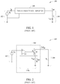
- FIG. 1 shows a known generic transconductance amplifier circuit 100.
- the transconductance amplifier circuit 100 includes an input stage 102, an output stage 104, and a transconductance amplifier 106.
- the transconductance amplifier circuit 100 can be thought of as a voltage-controlled current source that produces an output current I out in response to V in .
- the output stage 104 includes a load resistor R L , through which the output current I out flows to ground.
- Embodiments described herein present various configurations for the transconductance amplifier 106.
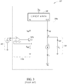
- FIG. 2 shows a known transconductance amplifier circuit 105.
- the transconductance amplifier circuit 105 includes the input stage 102 and the output stage 104 having a grounded load.
- the input stage 102 further includes an op-amp U1, an NPN bipolar junction transistor (BJT) Q0, and a precision reference resistor R ref .
- the NPN transistor Q0 has emitter, collector, and base terminals as is known in the art.
- the op-amp U1 has positive and negative input terminals and an output terminal, as is known in the art.
- V in is coupled directly to the positive terminal of U1
- R ref is coupled to the negative terminal of U1 at a node A.
- the output of U1 is coupled to the base of Q0.
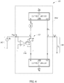
- FIG 3 shows a known transconductance amplifier circuit 107.
- the transconductance amplifier circuit 107 overcomes some limitations of the conventional transconductance amplifier circuit 105 of Figure 2 by adding a current mirror 108 and a current source I b for delivering current to grounded loads.
- the bias current I b is coupled to a negative supply voltage V ee .
- the output stage 104 is grounded.
- the current mirror 108 is coupled to a power supply V cc .
- a current I ref at the input is "mirrored" at the output of the current mirror 108. That is, the current mirror 108 responds to an input current by delivering an equivalent output current. This means that whichever current exits the input terminal of the current mirror 108 also exits the output terminal of the current mirror 108.
- the current mirror 108 has the effect of pushing current into the load R L as opposed to pulling current from the load.
- a transconductance amplifier 106a further includes the conventional op-amp stage 110a as shown in Figure 2 .
- the op-amp stage 110a includes the operational amplifier U1, the NPN transistor Q0, and the reference resistor R ref .
- the negative terminal of the op-amp U1 is coupled to ground via R ref .
- I ref V in / R ref .
- the need for a DC bias at the input of a transconductance amplifier can be a disadvantage. First, additional circuitry is required to provide the DC bias at the input. Second, adding a DC bias voltage at the input of an amplifier reduces the amount of signal headroom in the direction of the DC bias. Third, operating an amplifier near a power rail (V cc or V ee ) introduces distortion.
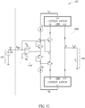
- FIG. 4 shows a virtual ground input stage 110b suitable for use in a low distortion transconductance amplifier 106b, according to an embodiment of the present disclosure.
- the transconductance amplifier 106b shown enclosed by a dotted line, includes the virtual ground input stage 110b and the bias current source I b .
- the virtual ground input stage 110b provides a current bias as a substitute for a DC bias voltage at the input stage, thus circumventing the problems described above that are associated with such a DC bias voltage.
- the voltage source V in is applied across a precision reference resistor R ref to produce an input current I in at an input node A.
- the current source I b is coupled to the emitter of Q1 and drives current through Q1. I b is desirably several times larger than the absolute value of the largest possible input current.
- the virtual ground input stage 110b includes the op-amp U1 and a PNP transistor Q1.
- an op-amp functions as a differential amplifier that boosts a voltage between the positive and negative input terminals by drawing energy from the power supply V cc .
- the op-amp U1 is not used as an amplifier in the virtual ground input stage 110b. Instead, the op-amp U1 is used to establish a virtual ground at input node A, below a bias resistor R B . Thus, U1 is coupled in a negative feedback configuration.
- the bias resistor R B not shown, sets the bias current to a desired value, and is represented in the Figures herein as an ideal current source instead of a resistor.
- the output terminal of U1 will settle to whatever voltage is necessary to force the positive and negative inputs of U1 to be at substantially the same voltage, V in - I in R ref .
- the output voltage of U1 is variable, and adjusts itself so as to force the differential voltage between the input terminals of U1 to be substantially zero. Because the positive input of U1 is grounded, the negative input is also held at 0V, which effectively grounds the input node A. Because the negative terminal of U1 is electrically isolated from ground, it is referred to as a "virtual ground.”
- the bias current I b flows from the power supply V cc through the bias resistor R B .
- the output stage 104 is coupled to the negative power supply V ee .
- I out I b + I in .
- the input current I in flows around U1 to the grounded node A and enters the emitter of Q1 where it is then delivered to the load R L .
- Use of the virtual ground input stage 110b will still require additional circuitry to deliver current to a grounded load. However, because an input current is used instead of a DC bias input voltage, the input stage has lower distortion and better noise performance. Additional zeroing circuitry is also not needed at the input. Furthermore, the virtual ground input stage 110b is able to handle input voltages of both positive and negative polarity.
- FIG. 5 shows a low distortion transconductance amplifier circuit 115, according to an embodiment of the present disclosure.
- the transconductance amplifier 106c shown enclosed by a dotted line, includes the virtual ground input stage 110b and two current mirrors 108a, 108b. By adding the current mirrors 108a, 108b to the circuit, the output current can be driven to a grounded load without the bias current I b being delivered to the load.
- the voltage source V in is applied across the precision reference resistor R ref to produce the input current I in at the input node A.
- the bias current I b drawn from the current mirror 108a.
- the current mirror 108a is coupled to the positive supply voltage V cc and the current mirror 108b is coupled to the negative supply voltage V ee .
- the virtual ground input stage 110b includes the op-amp U1 and the PNP transistor Q1. Establishing a virtual ground below R b draws current from V cc through the current mirror 108a.
- I out 0.
- the output stage 104 is grounded.
- FIG. 6 shows a low distortion transconductance amplifier circuit 121, according to an embodiment of the present disclosure.
- the transconductance amplifier 106d shown enclosed by a dotted line, includes a virtual ground input stage 110c and the two current mirrors 108a, 108b.
- the voltage source V in is applied across the precision reference resistor R ref to generate a current source I in at the input node A.
- V in can be an AC or a DC source.
- the bias current I b drawn from the current mirror 108a is also delivered to the input node A.
- the current mirror 108a is coupled to the positive supply voltage V cc and the current mirror 108b is coupled to the negative supply voltage V ee .
- the op-amp U1 drives the transistor Q2.
- the output stage 104 is grounded.
- the right side of R ref is connected to the negative terminal of U1.
- the positive terminal of U1 is connected to ground.
- the output of U1 forces the negative terminal of U1 to be the same as the positive terminal, that is, a "virtual ground” is created at the negative terminal of U1 so that the differential voltage across the inputs to the op-amp U1 is zero. Thus, node A is grounded.
- the virtual ground input stage 110c includes the op-amp U1 and a Darlington pair 122 of PNP transistors, Q1 and Q2.
- a bias current flows from Vcc down through R b and into the Darlington pair, Q1 and Q2.
- the Darlington pair has unity gain, i.e., no amplification. Therefore, in such embodiment, Q1 and Q2 could alternatively be replaced by a single transistor.
- Currents flowing out of the top current mirror 108a, I b are equal.
- currents flowing into the bottom current mirror 108b are also equal.
- the arrow side is the emitter and the other side is the collector.
- FIG 7 shows the low distortion transconductance amplifier circuit 121 of Figure 6 in greater detail.
- the input stage 102 includes the voltage source V in and the resistor R ref .
- the op-amp U1 is shown coupled between the power supplies V cc and V ee .
- the virtual ground input stage 110c may further include a voltage source V2 coupled between U1 and V cc , and a voltage source V3 coupled between U1 and V ee .
- the current mirrors 108a, 108b include bipolar junction transistors (BJTs) arranged in a lower transistor array corresponding to the current mirror 108b and an upper transistor array corresponding to the current mirror 108a.
- BJTs bipolar junction transistors
- the current mirrors 108a, 108b are powered by voltage supplies V cc and V ee , respectively.
- the lower current mirror 108b includes four BJTs, Q3, Q4, Q5, and Q6.
- Each BJT is a three-terminal device having an emitter, a base, and a collector. Exemplary labels are provided on the terminals of Q6 in Figure 7 .
- the base and the collector of Q6 are coupled together by a short circuit connection S1.
- the base and the collector of Q3 are coupled together by a short circuit connection S2.
- the upper current mirror 108a includes four BJTs, Q7, Q8, Q9, and Q10.
- the base and the collector of Q7 are coupled together by a short circuit connection S3.
- the base and the collector of Q10 are coupled together by a short circuit connection S4.
- Conventional op-amp based current mirrors have low frequency poles whereas the BJT current mirrors shown in Figure 7 have high frequency poles.
- BJTs the bandwidth of the current mirrors 108a, 108b is shifted to higher frequencies.
- FIG. 8 shows a low distortion transconductance amplifier circuit 123, according to an embodiment of the present disclosure.
- the transconductance amplifier 106e shown enclosed by a dotted line, includes a virtual ground input stage 110d and the two current mirrors 108a, 108b.
- the voltage source V is applied across the precision reference resistor R ref to produce the input current I in at the input node A.
- the current mirror 108a is coupled to the positive supply voltage V cc and the current mirror 108b is coupled to the negative supply voltage V ee .
- the virtual ground input stage 110d includes the op-amp U1 and a p-type metal-oxide-semiconductor (PMOS) field effect transistor M1, which is a substantially equivalent substitute for the PNP bipolar junction transistor Q1.
- PMOS metal-oxide-semiconductor
- M1 is particularly suitable for use at lower operating voltages, as is customary in the art.
- the transconductance amplifier circuit 123 is similar to the transconductance amplifier circuit 115.
- FIG. 9 shows a low distortion transconductance amplifier circuit 125, according to an embodiment of the present disclosure.
- the transconductance amplifier 106f shown enclosed by a dotted line, includes a virtual ground input stage 110e and the two current mirrors 108a, 108b.
- the voltage source V in is applied across the precision reference resistor R ref to produce the input current I in at the input node A.
- the current mirror 108a is coupled to the positive supply voltage V cc and the current mirror 108b is coupled to the negative supply voltage V ee .
- the virtual ground input stage 110e includes the op-amp U1 and an NPN transistor Q2.
- the positive terminal of U1 is grounded and I in is coupled to the negative terminal of U1.
- the node A is below the transistor Q2 instead of above Q2.
- the input stage shown in Figure 9 configured with the NPN transistor Q2 pulls current into the output stage 104 instead of pushing the current.
- the transconductance amplifier circuit 125 is similar to the transconductance amplifier circuit 115.
- FIG. 10 shows a low distortion transconductance amplifier circuit 127, according to an embodiment of the present disclosure.
- the transconductance amplifier 106g shown enclosed by a dotted line, includes the virtual ground input stage 110b and the two current mirrors 112a, 112b.
- the voltage source V in is applied across the precision reference resistor R ref to produce the input current I in at the input node A.
- the current mirror 112a is coupled to the positive supply voltage V cc and the current mirror 112b is coupled to the negative supply voltage V ee .
- the current mirrors 112a,b are current gain or current attenuation blocks that permit the signal level to be changed.
- the gain/attenuation blocks function in a similar way as the current mirrors 108, except that they output a current equal to a constant multiplied by the input current.
- the current mirrors 108a,b have an effective unity current gain.
- the virtual ground input stage 110b includes the op-amp U1 and the PNP transistor Q1 as in the transconductance amplifier circuit 115.
- FIG 11 shows a class B low distortion transconductance amplifier circuit 129, according to an embodiment.
- the transconductance amplifier 106h shown enclosed by a dotted line, includes the two current mirrors 108a, 108b and a virtual ground input stage 110f.
- the voltage source V in is applied across the precision reference resistor R ref to produce the input current I in at the input node A.
- the reference resistor R ref has a value of 1k ⁇ .
- the current mirror 108a is coupled to the positive supply voltage V cc and the current mirror 108b is coupled to the negative supply voltage V ee .
- the virtual ground input stage 110f includes the op-amp U1 and the PNP transistors Q1, Q2. However, unlike the Darlington pair embodiment shown in Figures 6 and 7 , Q1 and Q2 are coupled in series and the base of each transistor is coupled to the collector.
- the bias current source I b is coupled to V cc and a second bias current source I b2 is coupled to V ee .
- transistors Q7 and Q8 are coupled to the current mirrors 108a, 108b respectively.
- the low distortion transconductance amplifier circuit 129 can feature a linear transconductance amplifier as a class A, class B, or a hybrid class AB amplifier.
- Figure 12 shows steps in a method 150 of operating the low distortion transconductance circuits described above, according to an embodiment of the present disclosure.
- an input current source is created from an input voltage source V in and a reference resistor R ref .
- the input current source is coupled to a virtual ground.
- a bias resistor is coupled to the virtual ground
- the virtual ground is coupled to a current mirror to provide a bias current source I b .
- the bias current I b is supplied to the load resistor R L .
- the input current source I in is modulated to control the bias current I b .
- Examples provide a circuit, comprising a voltage source, a reference resistor coupled to the voltage source, an input stage including an operational amplifier coupled to the reference resistor, a transistor coupled to be driven by the operational amplifier, and a bias current source coupled to the transistor and the operational amplifier, an output stage including a grounded load resistor, and a pair of current mirrors, each current mirror coupling the input stage to the output stage.
- one or more of the current mirrors further includes first and second arrays of bipolar junction transistors.
- a current supplied to the output stage is equal to a difference in bias currents of the first and second arrays of the current mirror.
- the transistor is a first transistor and the circuit further comprises a second transistor arranged with the first transistor as a Darlington pair connecting the input stage to the pair of current mirrors.
- the transistors arranged as a Darlington pair collectively have unity gain.
- a positive terminal of the operational amplifier is grounded and the operational amplifier is configured to provide a virtual ground at a negative input terminal of the operational amplifier.
- the voltage source is a first voltage source and input terminals of the operational amplifier are coupled directly to second and third voltage sources, respectively.
- the transistor coupled to be driven by the operational amplifier is a bipolar junction transistor.
- the transistor coupled to be driven by the operational amplifier is a field effect transistor.
- the input stage is a pull input stage that pulls current into the load resistor.
- the pair of current mirrors is a pair of current attenuation mirrors.
- the pair of current mirrors is a pair of current gain mirrors.
- the circuit includes a linear transconductance amplifier.
- Examples provide a method of operating a circuit comprising creating an input current source by coupling an input voltage source to a reference resistor, coupling the current source to a virtual ground, coupling a bias resistor to the virtual ground, coupling the virtual ground to a current mirror that provides a bias current via the bias resistor, supplying the bias current to a load resistor, and controlling the bias current by modulating the input current source.
- the virtual ground is established by an operational amplifier.
- the current mirror includes first and second arrays of bipolar junction transistors.
- Examples provide a circuit, comprising a current source, a transconductance amplifier coupled to the current source, the transconductance amplifier having a virtual ground input stage, and an output stage coupled to the transconductance amplifier, the output stage having a grounded load.
- Some examples further comprise a pair of current mirrors coupled between the virtual ground input stage and the output stage.
- the virtual ground input stage includes two bipolar junction transistors arranged as a Darlington pair.
Landscapes
- Engineering & Computer Science (AREA)
- Power Engineering (AREA)
- Physics & Mathematics (AREA)
- Nonlinear Science (AREA)
- Amplifiers (AREA)
Abstract
Description
- This application claims the benefit of
U.S. Non-Provisional Application No. 15/162,963, filed May 24, 2016 - The present disclosure generally relates to precision transconductance amplifiers for use in electronic circuits.
- Some amplifiers used in electrical circuits are voltage amplifiers having an input voltage and a corresponding output voltage that is greater than the input voltage by a gain factor. Other amplifiers used in electrical circuits are current amplifiers having an input current and a corresponding output current that is greater than the input current by a gain factor. Still other amplifiers used in electrical circuits are transconductance amplifiers having an input voltage and a corresponding output current, or transresistance amplifiers having an input current and a corresponding output voltage. In addition to applying a gain, the transconductance and transresistance amplifiers provide a voltage-to-current or current-to-voltage conversion function, respectively.
- Such a conversion function can be implemented in several ways. For example, when a resistor is connected between a DC voltage source, V, and ground, a current, I, flows through the resistor. Therefore, the resistor can be thought of as a device that converts a voltage to a current, wherein the output current is proportional to the applied input voltage, according to Ohm's law: I = V/R, or I = GV. When a voltage source connected to a resistor is further connected in series with an amplifier stage, the result is a transconductance amplifier. Like a resistor, a transconductance amplifier also outputs a current that is proportional to its input voltage. The amplifier stage can be, for example, a transistor, an operational amplifier ("op-amp") or an arrangement of transistors. The resulting transconductance amplifier provides a voltage-controlled current source for use in electronic circuits, as is known in the art.
- Transconductance refers to conductance across a direct current (DC) device, that is, the conductance between the input and the output of the device. Conductance, G, is defined as the reciprocal of resistance in a DC circuit: G (mhos) = 1/R (Ω). The term "admittance" refers to conductance in an alternating current (AC) circuit, or the reciprocal of impedance: Y (mhos) = 1/Z (Ω), as is well known in the art. The AC equivalent of transconductance is then transadmittance.
- A Darlington pair is known in the art of circuit design as a pair of bipolar transistors in which the output current of the first transistor is further amplified by the second transistor. A Darlington pair thus behaves as a single transistor with a high current gain, approximately equal to the square of the gain of a single transistor. A disadvantage of a Darlington pair is that it tends to become unstable at high frequencies, so its operational bandwidth is limited.
- A current mirror is known in the art of circuit design as an electrical circuit that can be used to provide a bias current to a load. A current mirror can be thought of as a current-controlled current source.
- A low distortion transconductance amplifier provides current to a grounded load using a virtual ground input stage, a pair of current mirrors, and a bias current source. The virtual ground input stage may include transistors arranged as a Darlington pair. The low distortion transconductance amplifier can function as a voltage-controlled AC current source that is operable at high frequencies.
-
-
Figure 1 is a high level schematic of a basic transconductance amplifier circuit, according to the prior art. -
Figure 2 is a schematic of a transconductance amplifier circuit according to the prior art. -
Figure 3 is a schematic of a transconductance amplifier circuit that includes a current mirror and a virtual ground input stage, according to the prior art. -
Figure 4 is a circuit schematic of a virtual ground input stage suitable for use in a transconductance amplifier, according to an embodiment as described herein. -
Figure 5 is a high level schematic of a transconductance amplifier circuit that includes two current mirrors and a virtual ground input stage, according to an embodiment as described herein. -
Figure 6 is a schematic of a transconductance amplifier circuit implemented with a Darlington pair, according to an embodiment as described herein. -
Figure 7 is a detailed schematic of the transconductance amplifier circuit shown inFigure 6 . -
Figure 8 is a schematic of a transconductance amplifier circuit implemented with a field effect transistor, according to an embodiment as described herein. -
Figure 9 is a schematic of a transconductance amplifier circuit implemented with a pull input stage, according to an embodiment as described herein. -
Figure 10 is a schematic of a transconductance amplifier circuit implemented with current gain or attenuation mirrors, according to an embodiment as described herein. -
Figure 11 is a schematic of a class B transconductance amplifier circuit, according to an embodiment as described herein. -
Figure 12 is a flow diagram illustrating a method of operating a transconductance amplifier circuit, according to an embodiment as described herein. - In the following description, certain specific details are set forth in order to provide a thorough understanding of various aspects of the disclosed subject matter. However, the disclosed subject matter may be practiced without these specific details. In some instances, well-known structures and methods comprising embodiments of the subject matter disclosed herein have not been described in detail to avoid obscuring the descriptions of other aspects of the present disclosure.
- Unless the context requires otherwise, throughout the specification and claims that follow, the word "comprise" and variations thereof, such as "comprises" and "comprising" are to be construed in an open, inclusive sense, that is, as "including, but not limited to."
- Reference throughout the specification to "one embodiment" or "an embodiment" means that a particular feature, structure, or characteristic described in connection with the embodiment is included in at least one embodiment. Thus, the appearance of the phrases "In an embodiment" or "in an embodiment" in various places throughout the specification are not necessarily all referring to the same embodiment. Furthermore, the particular features, structures, or characteristics may be combined in any suitable manner in one or more aspects of the present disclosure.
- In the figures, identical reference numbers identify similar features or elements. The sizes and relative positions of the features in the figures are not necessarily drawn to scale. Furthermore, specific embodiments are described herein with reference to exemplary transconductance amplifier circuits. The present disclosure and the reference to certain materials, dimensions, and the details and ordering of method steps should not be limited to those shown.
-
Figure 1 shows a known generictransconductance amplifier circuit 100. Thetransconductance amplifier circuit 100 includes aninput stage 102, anoutput stage 104, and atransconductance amplifier 106. Thetransconductance amplifier circuit 100 can be thought of as a voltage-controlled current source that produces an output current Iout in response to Vin. Theoutput stage 104 includes a load resistor RL, through which the output current Iout flows to ground. The relationship between the input voltage and the output current is
transconductance amplifier 106. Embodiments described herein present various configurations for thetransconductance amplifier 106. -
Figure 2 shows a knowntransconductance amplifier circuit 105. Thetransconductance amplifier circuit 105 includes theinput stage 102 and theoutput stage 104 having a grounded load. In thetransconductance amplifier circuit 105, theinput stage 102 further includes an op-amp U1, an NPN bipolar junction transistor (BJT) Q0, and a precision reference resistor Rref. The NPN transistor Q0 has emitter, collector, and base terminals as is known in the art. The op-amp U1 has positive and negative input terminals and an output terminal, as is known in the art. In thetransconductance amplifier circuit 105, Vin is coupled directly to the positive terminal of U1, and Rref is coupled to the negative terminal of U1 at a node A. The output of U1 is coupled to the base of Q0. The emitter terminal of Q1 is coupled to node A. If the current gain of Q0 is large enough,
transconductance amplifier 106 is then
- Existing transconductance amplifiers capable of converting a single-ended input voltage to a single-ended ground-referenced output current typically use op-amp based voltage-to-current converters such as the one shown in
Figure 2 . However, such amplifiers have limitations on the load RL. In practice, a grounded load is not possible due to input range and output range limitations illustrated by the following example. It is noted that Vin must be positive for Q1 to be in forward active mode (Vbe ≥ 0.7V and Vce ≥ 0.2V). The restriction Vin ≥ 0 means Iout ≥ 0. Furthermore, Vout = Vin + Vce. Therefore, Vout ≥ Vin + 0.2V, which requires that RL < 0. -
Figure 3 shows a knowntransconductance amplifier circuit 107. Thetransconductance amplifier circuit 107 overcomes some limitations of the conventionaltransconductance amplifier circuit 105 ofFigure 2 by adding acurrent mirror 108 and a current source Ib for delivering current to grounded loads. The bias current Ib is coupled to a negative supply voltage Vee. In thetransconductance amplifier circuit 107, theoutput stage 104 is grounded. - The
current mirror 108 is coupled to a power supply Vcc. When the transistor Q0 switches on, a current Iref at the input is "mirrored" at the output of thecurrent mirror 108. That is, thecurrent mirror 108 responds to an input current by delivering an equivalent output current. This means that whichever current exits the input terminal of thecurrent mirror 108 also exits the output terminal of thecurrent mirror 108. Thecurrent mirror 108 has the effect of pushing current into the load RL as opposed to pulling current from the load. - In the
transconductance amplifier circuit 107, atransconductance amplifier 106a further includes the conventional op-amp stage 110a as shown inFigure 2 . The op-amp stage 110a includes the operational amplifier U1, the NPN transistor Q0, and the reference resistor Rref. The negative terminal of the op-amp U1 is coupled to ground via Rref. The output of U1 is coupled to the base terminal of Q0 and the emitter terminal of Q0 is coupled to the negative input of U1, such that Iref = Vin / Rref. Adding the current source Ib changes the transconductance gain relationship to be:
transconductance amplifier 107 delivers negative output current to an arbitrary load. This eliminates the limitation Iout ≥ 0. However, when Iout = 0, the input voltage is non-zero, i.e., a DC bias is applied: Vin = Ib Rref. The need for a DC bias at the input of a transconductance amplifier can be a disadvantage. First, additional circuitry is required to provide the DC bias at the input. Second, adding a DC bias voltage at the input of an amplifier reduces the amount of signal headroom in the direction of the DC bias. Third, operating an amplifier near a power rail (Vcc or Vee) introduces distortion. -
Figure 4 shows a virtualground input stage 110b suitable for use in a lowdistortion transconductance amplifier 106b, according to an embodiment of the present disclosure. Thetransconductance amplifier 106b, shown enclosed by a dotted line, includes the virtualground input stage 110b and the bias current source Ib. The virtualground input stage 110b provides a current bias as a substitute for a DC bias voltage at the input stage, thus circumventing the problems described above that are associated with such a DC bias voltage. In theinput stage 102, the voltage source Vin is applied across a precision reference resistor Rref to produce an input current Iin at an input node A. Instead of biasing Q1 using an input bias voltage, the current source Ib is coupled to the emitter of Q1 and drives current through Q1. Ib is desirably several times larger than the absolute value of the largest possible input current. - The virtual
ground input stage 110b includes the op-amp U1 and a PNP transistor Q1. In a conventional op-amp implementation, an op-amp functions as a differential amplifier that boosts a voltage between the positive and negative input terminals by drawing energy from the power supply Vcc. However, the op-amp U1 is not used as an amplifier in the virtualground input stage 110b. Instead, the op-amp U1 is used to establish a virtual ground at input node A, below a bias resistor RB. Thus, U1 is coupled in a negative feedback configuration. It is noted that the bias resistor RB, not shown, sets the bias current to a desired value, and is represented in the Figures herein as an ideal current source instead of a resistor. Consequently, the output terminal of U1 will settle to whatever voltage is necessary to force the positive and negative inputs of U1 to be at substantially the same voltage, Vin - Iin Rref. The output voltage of U1 is variable, and adjusts itself so as to force the differential voltage between the input terminals of U1 to be substantially zero. Because the positive input of U1 is grounded, the negative input is also held at 0V, which effectively grounds the input node A. Because the negative terminal of U1 is electrically isolated from ground, it is referred to as a "virtual ground." The bias current Ib flows from the power supply Vcc through the bias resistor RB. Theoutput stage 104 is coupled to the negative power supply Vee. When Q1 is switched on, Iout = Ib + Iin. The input current Iin flows around U1 to the grounded node A and enters the emitter of Q1 where it is then delivered to the load RL. Use of the virtualground input stage 110b will still require additional circuitry to deliver current to a grounded load. However, because an input current is used instead of a DC bias input voltage, the input stage has lower distortion and better noise performance. Additional zeroing circuitry is also not needed at the input. Furthermore, the virtualground input stage 110b is able to handle input voltages of both positive and negative polarity. -
Figure 5 shows a low distortiontransconductance amplifier circuit 115, according to an embodiment of the present disclosure. In the low distortiontransconductance amplifier circuit 115, thetransconductance amplifier 106c, shown enclosed by a dotted line, includes the virtualground input stage 110b and twocurrent mirrors current mirrors - In the
input stage 102, the voltage source Vin is applied across the precision reference resistor Rref to produce the input current Iin at the input node A. Also delivered to the input node A is the bias current Ib drawn from thecurrent mirror 108a. Thecurrent mirror 108a is coupled to the positive supply voltage Vcc and thecurrent mirror 108b is coupled to the negative supply voltage Vee. The virtualground input stage 110b includes the op-amp U1 and the PNP transistor Q1. Establishing a virtual ground below Rb draws current from Vcc through thecurrent mirror 108a. Iout is then equal to the difference between the top and bottom bias currents at output node B:
transconductance amplifier circuit 115, theoutput stage 104 is grounded. -
Figure 6 shows a low distortiontransconductance amplifier circuit 121, according to an embodiment of the present disclosure. In the low distortiontransconductance amplifier circuit 121, thetransconductance amplifier 106d, shown enclosed by a dotted line, includes a virtualground input stage 110c and the twocurrent mirrors input stage 102, the voltage source Vin is applied across the precision reference resistor Rref to generate a current source Iin at the input node A. Vin can be an AC or a DC source. Also delivered to the input node A is the bias current Ib drawn from thecurrent mirror 108a. Thecurrent mirror 108a is coupled to the positive supply voltage Vcc and thecurrent mirror 108b is coupled to the negative supply voltage Vee. The op-amp U1 drives the transistor Q2. In thetransconductance amplifier circuit 121, theoutput stage 104 is grounded. - The right side of Rref is connected to the negative terminal of U1. The positive terminal of U1 is connected to ground. The output of U1 forces the negative terminal of U1 to be the same as the positive terminal, that is, a "virtual ground" is created at the negative terminal of U1 so that the differential voltage across the inputs to the op-amp U1 is zero. Thus, node A is grounded.
- The virtual
ground input stage 110c includes the op-amp U1 and aDarlington pair 122 of PNP transistors, Q1 and Q2. A bias current flows from Vcc down through Rb and into the Darlington pair, Q1 and Q2. In one embodiment, the Darlington pair has unity gain, i.e., no amplification. Therefore, in such embodiment, Q1 and Q2 could alternatively be replaced by a single transistor. Currents flowing out of the topcurrent mirror 108a, Ib, are equal. Likewise, currents flowing into the bottomcurrent mirror 108b are also equal. In each one of Q1 and Q2, the arrow side is the emitter and the other side is the collector. -
Figure 7 shows the low distortiontransconductance amplifier circuit 121 ofFigure 6 in greater detail. Theinput stage 102 includes the voltage source Vin and the resistor Rref. The op-amp U1 is shown coupled between the power supplies Vcc and Vee. The virtualground input stage 110c may further include a voltage source V2 coupled between U1 and Vcc, and a voltage source V3 coupled between U1 and Vee. Thecurrent mirrors current mirror 108b and an upper transistor array corresponding to thecurrent mirror 108a. Thecurrent mirrors current mirror 108b includes four BJTs, Q3, Q4, Q5, and Q6. Each BJT is a three-terminal device having an emitter, a base, and a collector. Exemplary labels are provided on the terminals of Q6 inFigure 7 . The base and the collector of Q6 are coupled together by a short circuit connection S1. The base and the collector of Q3 are coupled together by a short circuit connection S2. The uppercurrent mirror 108a includes four BJTs, Q7, Q8, Q9, and Q10. The base and the collector of Q7 are coupled together by a short circuit connection S3. The base and the collector of Q10 are coupled together by a short circuit connection S4. Conventional op-amp based current mirrors have low frequency poles whereas the BJT current mirrors shown inFigure 7 have high frequency poles. Hence, through the use of BJTs, the bandwidth of thecurrent mirrors -
Figure 8 shows a low distortiontransconductance amplifier circuit 123, according to an embodiment of the present disclosure. In the low distortiontransconductance amplifier circuit 123, thetransconductance amplifier 106e, shown enclosed by a dotted line, includes a virtualground input stage 110d and the twocurrent mirrors input stage 102, the voltage source V is applied across the precision reference resistor Rref to produce the input current Iin at the input node A. Thecurrent mirror 108a is coupled to the positive supply voltage Vcc and thecurrent mirror 108b is coupled to the negative supply voltage Vee. The virtualground input stage 110d includes the op-amp U1 and a p-type metal-oxide-semiconductor (PMOS) field effect transistor M1, which is a substantially equivalent substitute for the PNP bipolar junction transistor Q1. M1 is particularly suitable for use at lower operating voltages, as is customary in the art. Otherwise, thetransconductance amplifier circuit 123 is similar to thetransconductance amplifier circuit 115. -
Figure 9 shows a low distortiontransconductance amplifier circuit 125, according to an embodiment of the present disclosure. In the low distortiontransconductance amplifier circuit 125, thetransconductance amplifier 106f, shown enclosed by a dotted line, includes a virtualground input stage 110e and the twocurrent mirrors input stage 102, the voltage source Vin is applied across the precision reference resistor Rref to produce the input current Iin at the input node A. Thecurrent mirror 108a is coupled to the positive supply voltage Vcc and thecurrent mirror 108b is coupled to the negative supply voltage Vee. The virtualground input stage 110e includes the op-amp U1 and an NPN transistor Q2. The positive terminal of U1 is grounded and Iin is coupled to the negative terminal of U1. However, the node A is below the transistor Q2 instead of above Q2. The input stage shown inFigure 9 configured with the NPN transistor Q2 pulls current into theoutput stage 104 instead of pushing the current. Otherwise, thetransconductance amplifier circuit 125 is similar to thetransconductance amplifier circuit 115. -
Figure 10 shows a low distortiontransconductance amplifier circuit 127, according to an embodiment of the present disclosure. In the low distortiontransconductance amplifier circuit 127, thetransconductance amplifier 106g, shown enclosed by a dotted line, includes the virtualground input stage 110b and the twocurrent mirrors 112a, 112b. In theinput stage 102, the voltage source Vin is applied across the precision reference resistor Rref to produce the input current Iin at the input node A. Thecurrent mirror 112a is coupled to the positive supply voltage Vcc and the current mirror 112b is coupled to the negative supply voltage Vee. Thecurrent mirrors 112a,b are current gain or current attenuation blocks that permit the signal level to be changed. The gain/attenuation blocks function in a similar way as thecurrent mirrors 108, except that they output a current equal to a constant multiplied by the input current. Iout/Iin < 1 for a current attenuation block, and Iout/Iin > 1 for a current gain block. In contrast, thecurrent mirrors 108a,b have an effective unity current gain. The virtualground input stage 110b includes the op-amp U1 and the PNP transistor Q1 as in thetransconductance amplifier circuit 115. -
Figure 11 shows a class B low distortiontransconductance amplifier circuit 129, according to an embodiment. In the class Btransconductance amplifier circuit 129, thetransconductance amplifier 106h, shown enclosed by a dotted line, includes the twocurrent mirrors ground input stage 110f. In theinput stage 102, the voltage source Vin is applied across the precision reference resistor Rref to produce the input current Iin at the input node A. In at least one example, the reference resistor Rref has a value of 1kΩ. Thecurrent mirror 108a is coupled to the positive supply voltage Vcc and thecurrent mirror 108b is coupled to the negative supply voltage Vee. The virtualground input stage 110f includes the op-amp U1 and the PNP transistors Q1, Q2. However, unlike the Darlington pair embodiment shown inFigures 6 and7 , Q1 and Q2 are coupled in series and the base of each transistor is coupled to the collector. The bias current source Ib is coupled to Vcc and a second bias current source Ib2 is coupled to Vee. In addition, transistors Q7 and Q8 are coupled to thecurrent mirrors transconductance amplifier circuit 129 can feature a linear transconductance amplifier as a class A, class B, or a hybrid class AB amplifier. -
Figure 12 shows steps in amethod 150 of operating the low distortion transconductance circuits described above, according to an embodiment of the present disclosure. - At 152, an input current source is created from an input voltage source Vin and a reference resistor Rref.
- At 154, the input current source is coupled to a virtual ground.
- At 156, a bias resistor is coupled to the virtual ground,
- At 158, the virtual ground is coupled to a current mirror to provide a bias current source Ib.
- At 160, the bias current Ib is supplied to the load resistor RL.
- At 162, the input current source Iin is modulated to control the bias current Ib.
- Examples provide a circuit, comprising a voltage source, a reference resistor coupled to the voltage source, an input stage including an operational amplifier coupled to the reference resistor, a transistor coupled to be driven by the operational amplifier, and a bias current source coupled to the transistor and the operational amplifier, an output stage including a grounded load resistor, and a pair of current mirrors, each current mirror coupling the input stage to the output stage.
- In some examples, one or more of the current mirrors further includes first and second arrays of bipolar junction transistors.
- In some examples, a current supplied to the output stage is equal to a difference in bias currents of the first and second arrays of the current mirror.
- In some examples, the transistor is a first transistor and the circuit further comprises a second transistor arranged with the first transistor as a Darlington pair connecting the input stage to the pair of current mirrors.
- In some examples, the transistors arranged as a Darlington pair collectively have unity gain.
- In some examples, a positive terminal of the operational amplifier is grounded and the operational amplifier is configured to provide a virtual ground at a negative input terminal of the operational amplifier.
- In some examples, the voltage source is a first voltage source and input terminals of the operational amplifier are coupled directly to second and third voltage sources, respectively.
- In some examples, the transistor coupled to be driven by the operational amplifier is a bipolar junction transistor.
- In some examples, the transistor coupled to be driven by the operational amplifier is a field effect transistor.
- In some examples, the input stage is a pull input stage that pulls current into the load resistor.
- In some examples, the pair of current mirrors is a pair of current attenuation mirrors.
- In some examples, the pair of current mirrors is a pair of current gain mirrors.
- In some examples, the circuit includes a linear transconductance amplifier.
- Examples provide a method of operating a circuit comprising creating an input current source by coupling an input voltage source to a reference resistor, coupling the current source to a virtual ground, coupling a bias resistor to the virtual ground, coupling the virtual ground to a current mirror that provides a bias current via the bias resistor, supplying the bias current to a load resistor, and controlling the bias current by modulating the input current source.
- In some examples, the virtual ground is established by an operational amplifier.
- In some examples, the current mirror includes first and second arrays of bipolar junction transistors.
- Examples provide a circuit, comprising a current source, a transconductance amplifier coupled to the current source, the transconductance amplifier having a virtual ground input stage, and an output stage coupled to the transconductance amplifier, the output stage having a grounded load.
- Some examples further comprise a pair of current mirrors coupled between the virtual ground input stage and the output stage.
- In some examples the virtual ground input stage includes two bipolar junction transistors arranged as a Darlington pair.
- It will be appreciated that, although specific embodiments of the present disclosure are described herein for purposes of illustration, various modifications may be made without departing from the scope of the present disclosure. The various embodiments described above can be combined to provide further embodiments. Aspects of the embodiments can be modified, if necessary to employ concepts of various other patents, patent applications and publications to provide yet further embodiments.
- These and other changes can be made to the embodiments in light of the above-detailed description. In general, in the following claims, the terms used should not be construed to limit the claims to the specific embodiments disclosed in the specification and the claims, but should be construed to include all possible embodiments along with the full scope of equivalents to which such claims are entitled. Accordingly, the claims are not limited by the disclosure.
Claims (15)
- A circuit, comprising:a current source;a transconductance amplifier coupled to the current source, the transconductance amplifier having a virtual ground input stage; andan output stage coupled to the transconductance amplifier, the output stage having a grounded load.
- The circuit of claim 1, further comprising a pair of current mirrors coupled between the virtual ground input stage and the output stage.
- The circuit of claim 1 or 2, wherein the virtual ground input stage includes two bipolar junction transistors arranged as a Darlington pair.
- The circuit of any preceding claim, wherein the current source includes a voltage source and a reference resistor coupled to the voltage source; and
wherein the virtual ground input stage includes
an operational amplifier coupled to the reference resistor;
a transistor coupled to be driven by the operational amplifier; and
a bias current source coupled to the transistor and the operational amplifier. - The circuit of claim 2, wherein one or more of the current mirrors further includes first and second arrays of bipolar junction transistors.
- The circuit of claim 5, wherein a current supplied to the output stage is equal to a difference in bias currents of the first and second arrays of the current mirror.
- The circuit of any of claims 4 to 6, wherein the transistor is a first transistor and further comprises a second transistor arranged with the first transistor as a Darlington pair connecting the input stage to the pair of current mirrors.
- The circuit of claim 7, wherein the transistors arranged as a Darlington pair collectively have unity gain.
- The circuit of any of claims 4 to 8, wherein a positive terminal of the operational amplifier is grounded and the operational amplifier is configured to provide a virtual ground at a negative input terminal of the operational amplifier.
- The circuit of any of claims 4 to 9, wherein the voltage source is a first voltage source and input terminals of the operational amplifier are coupled directly to second and third voltage sources, respectively.
- The circuit of any of claims 4 to 10, wherein the transistor coupled to be driven by the operational amplifier is a bipolar junction transistor or a field effect transistor.
- The circuit of any of claims 4 to 11, wherein the input stage is a pull input stage that pulls current into the load resistor.
- The circuit of any of claims 4 to 12, wherein the pair of current mirrors is a pair of current attenuation mirrors or a pair of current gain mirrors.
- The circuit of any preceding claim, wherein the transconductance amplifier is a linear transconductance amplifier.
- A method of operating a circuit comprising:creating an input current source by coupling an input voltage source to a reference resistor;coupling the current source to a virtual ground, wherein preferably the virtual ground is established by an operational amplifier;coupling a bias resistor to the virtual ground;coupling the virtual ground to a current mirror that provides a bias current via the bias resistor, wherein preferably the current mirror includes first and second arrays of bipolar junction transistors;supplying the bias current to a load resistor; andcontrolling the bias current by modulating the input current source.
Applications Claiming Priority (1)
| Application Number | Priority Date | Filing Date | Title |
|---|---|---|---|
| US15/162,963 US9929705B2 (en) | 2016-05-24 | 2016-05-24 | Transconductance amplifier having low distortion |
Publications (2)
| Publication Number | Publication Date |
|---|---|
| EP3249810A1 true EP3249810A1 (en) | 2017-11-29 |
| EP3249810B1 EP3249810B1 (en) | 2022-11-02 |
Family
ID=58772788
Family Applications (1)
| Application Number | Title | Priority Date | Filing Date |
|---|---|---|---|
| EP17172869.4A Active EP3249810B1 (en) | 2016-05-24 | 2017-05-24 | Transconductance amplifier having low distortion |
Country Status (4)
| Country | Link |
|---|---|
| US (1) | US9929705B2 (en) |
| EP (1) | EP3249810B1 (en) |
| JP (1) | JP7095958B2 (en) |
| CN (1) | CN107425817B (en) |
Families Citing this family (8)
| Publication number | Priority date | Publication date | Assignee | Title |
|---|---|---|---|---|
| US10270393B1 (en) * | 2018-03-22 | 2019-04-23 | Linear Technology Holding Llc | Transconductance amplifier with nonlinear transconductance and low quiescent current |
| JP7008568B2 (en) * | 2018-04-13 | 2022-01-25 | 新日本無線株式会社 | Resolver excitation circuit |
| US11323085B2 (en) * | 2019-09-04 | 2022-05-03 | Analog Devices International Unlimited Company | Voltage-to-current converter with complementary current mirrors |
| EP3826174A4 (en) * | 2019-09-26 | 2021-08-25 | Shenzhen Goodix Technology Co., Ltd. | TRANSCONDUCTANCE AMPLIFIER AND CHIP |
| CN111082800B (en) * | 2019-12-19 | 2024-09-17 | 王仲季 | I/V converter |
| US11272598B2 (en) * | 2020-02-07 | 2022-03-08 | Analog Devices International Unlimited Company | Transconductance circuits and methods |
| WO2022026964A1 (en) * | 2020-07-31 | 2022-02-03 | Microchip Technology Incorporated | Multi-bias mode current conveyor, configuring a multi‑bias mode current conveyor, touch sensing systems including a multi-bias mode current conveyor, and related systems, methods and devices |
| JP7824070B2 (en) * | 2021-12-24 | 2026-03-04 | ローム株式会社 | Operational Amplifiers |
Citations (3)
| Publication number | Priority date | Publication date | Assignee | Title |
|---|---|---|---|---|
| US5973563A (en) * | 1997-12-10 | 1999-10-26 | National Semiconductor Corporation | High power output stage with temperature stable precisely controlled quiescent current and inherent short circuit protection |
| US6411164B1 (en) * | 2000-08-14 | 2002-06-25 | Intersil Americas Inc. | Precision low power operational amplifier with gain invariant bandwith |
| US6731165B1 (en) * | 2003-01-06 | 2004-05-04 | Daniel J. Marz | Electronic amplifier |
Family Cites Families (14)
| Publication number | Priority date | Publication date | Assignee | Title |
|---|---|---|---|---|
| US3898578A (en) * | 1973-05-18 | 1975-08-05 | Nasa | Integrable power gyrator |
| JPH067310U (en) * | 1992-06-25 | 1994-01-28 | 明 永井 | amplifier |
| JPH0652223U (en) * | 1992-06-29 | 1994-07-15 | 明 永井 | Current-voltage converter |
| JP2853485B2 (en) * | 1992-11-10 | 1999-02-03 | 日本電気株式会社 | Voltage-current converter |
| JP2896029B2 (en) * | 1992-11-30 | 1999-05-31 | 三洋電機株式会社 | Voltage-current converter |
| JPH077337A (en) * | 1993-06-16 | 1995-01-10 | Nec Corp | Bipolarity voltage/current converting circuit |
| WO1996027238A1 (en) | 1995-03-01 | 1996-09-06 | Lattice Semiconductor Corporation | Low distortion differential transconductor output current mirror |
| JP2904128B2 (en) * | 1996-06-28 | 1999-06-14 | 日本電気株式会社 | Output circuit |
| US6011415A (en) * | 1996-10-21 | 2000-01-04 | Texas Instruments Incorporated | Shock sensor circuitry and method for amplifying an input signal including leakage currents |
| US6538507B2 (en) * | 2001-02-28 | 2003-03-25 | Intersil Americas, Inc. | Automatic gain control circuit with high linearity and monotonically correlated offset voltage |
| TW200951669A (en) * | 2008-06-04 | 2009-12-16 | Raydium Semiconductor Corp | Current source |
| JP2010056643A (en) * | 2008-08-26 | 2010-03-11 | Mitsutoyo Corp | Motor driver circuit |
| JP5691158B2 (en) * | 2009-11-13 | 2015-04-01 | ミツミ電機株式会社 | Output current detection circuit and transmission circuit |
| CN103326682A (en) * | 2013-05-27 | 2013-09-25 | 苏州贝克微电子有限公司 | Adjustable operational transconductance amplifier with high linearity |
-
2016
- 2016-05-24 US US15/162,963 patent/US9929705B2/en active Active
-
2017
- 2017-05-23 JP JP2017101486A patent/JP7095958B2/en active Active
- 2017-05-24 CN CN201710373816.2A patent/CN107425817B/en active Active
- 2017-05-24 EP EP17172869.4A patent/EP3249810B1/en active Active
Patent Citations (3)
| Publication number | Priority date | Publication date | Assignee | Title |
|---|---|---|---|---|
| US5973563A (en) * | 1997-12-10 | 1999-10-26 | National Semiconductor Corporation | High power output stage with temperature stable precisely controlled quiescent current and inherent short circuit protection |
| US6411164B1 (en) * | 2000-08-14 | 2002-06-25 | Intersil Americas Inc. | Precision low power operational amplifier with gain invariant bandwith |
| US6731165B1 (en) * | 2003-01-06 | 2004-05-04 | Daniel J. Marz | Electronic amplifier |
Also Published As
| Publication number | Publication date |
|---|---|
| JP7095958B2 (en) | 2022-07-05 |
| US20170346454A1 (en) | 2017-11-30 |
| EP3249810B1 (en) | 2022-11-02 |
| US9929705B2 (en) | 2018-03-27 |
| CN107425817B (en) | 2023-04-07 |
| CN107425817A (en) | 2017-12-01 |
| JP2017212735A (en) | 2017-11-30 |
Similar Documents
| Publication | Publication Date | Title |
|---|---|---|
| EP3249810B1 (en) | Transconductance amplifier having low distortion | |
| US5374897A (en) | Balanced, high-speed differential input stage for Op-amps | |
| US6538514B2 (en) | Compensation method in a class-G amplifier output stage | |
| JPH11504791A (en) | Operational amplifier | |
| EP0806080B1 (en) | Amplifier | |
| US6437631B2 (en) | Analog multiplying circuit and variable gain amplifying circuit | |
| KR940006337A (en) | Wide Frequency Amplifier | |
| US4719431A (en) | Audio power amplifier | |
| JP2025513459A (en) | Differential current buffer circuit and DC and AC power supply including the same | |
| EP1230730B1 (en) | Amplifier with improved, high precision, high speed and low power consumption architecture | |
| JP2619858B2 (en) | Function approximation function generator | |
| JP3058087B2 (en) | Variable gain amplifier | |
| JPS6138269Y2 (en) | ||
| EP3713082B1 (en) | Amplification circuit | |
| EP3364540A1 (en) | Audio amplifier and audio power amplifier | |
| JPH02312403A (en) | Clipping circuit | |
| JP3216753B2 (en) | DA conversion circuit device | |
| KR100918789B1 (en) | Image Display Devices, Integrated Circuits, and Driver Circuits | |
| JP3146088B2 (en) | Variable reactance circuit | |
| RU2156537C1 (en) | Linear power amplifier | |
| JP2759156B2 (en) | Amplifier circuit | |
| JPS6123687B2 (en) | ||
| KR900702645A (en) | Improved Variable Loss | |
| JPH1155048A (en) | Power amplifier, power amplifier and regulator | |
| JPS58186208A (en) | Automatic gain control amplifier |
Legal Events
| Date | Code | Title | Description |
|---|---|---|---|
| PUAI | Public reference made under article 153(3) epc to a published international application that has entered the european phase |
Free format text: ORIGINAL CODE: 0009012 |
|
| STAA | Information on the status of an ep patent application or granted ep patent |
Free format text: STATUS: THE APPLICATION HAS BEEN PUBLISHED |
|
| AK | Designated contracting states |
Kind code of ref document: A1 Designated state(s): AL AT BE BG CH CY CZ DE DK EE ES FI FR GB GR HR HU IE IS IT LI LT LU LV MC MK MT NL NO PL PT RO RS SE SI SK SM TR |
|
| AX | Request for extension of the european patent |
Extension state: BA ME |
|
| STAA | Information on the status of an ep patent application or granted ep patent |
Free format text: STATUS: REQUEST FOR EXAMINATION WAS MADE |
|
| 17P | Request for examination filed |
Effective date: 20180529 |
|
| RBV | Designated contracting states (corrected) |
Designated state(s): AL AT BE BG CH CY CZ DE DK EE ES FI FR GB GR HR HU IE IS IT LI LT LU LV MC MK MT NL NO PL PT RO RS SE SI SK SM TR |
|
| STAA | Information on the status of an ep patent application or granted ep patent |
Free format text: STATUS: EXAMINATION IS IN PROGRESS |
|
| 17Q | First examination report despatched |
Effective date: 20200626 |
|
| GRAP | Despatch of communication of intention to grant a patent |
Free format text: ORIGINAL CODE: EPIDOSNIGR1 |
|
| STAA | Information on the status of an ep patent application or granted ep patent |
Free format text: STATUS: GRANT OF PATENT IS INTENDED |
|
| INTG | Intention to grant announced |
Effective date: 20220524 |
|
| GRAS | Grant fee paid |
Free format text: ORIGINAL CODE: EPIDOSNIGR3 |
|
| GRAA | (expected) grant |
Free format text: ORIGINAL CODE: 0009210 |
|
| STAA | Information on the status of an ep patent application or granted ep patent |
Free format text: STATUS: THE PATENT HAS BEEN GRANTED |
|
| AK | Designated contracting states |
Kind code of ref document: B1 Designated state(s): AL AT BE BG CH CY CZ DE DK EE ES FI FR GB GR HR HU IE IS IT LI LT LU LV MC MK MT NL NO PL PT RO RS SE SI SK SM TR |
|
| REG | Reference to a national code |
Ref country code: GB Ref legal event code: FG4D |
|
| REG | Reference to a national code |
Ref country code: CH Ref legal event code: EP Ref country code: AT Ref legal event code: REF Ref document number: 1529517 Country of ref document: AT Kind code of ref document: T Effective date: 20221115 |
|
| REG | Reference to a national code |
Ref country code: DE Ref legal event code: R096 Ref document number: 602017063203 Country of ref document: DE |
|
| REG | Reference to a national code |
Ref country code: IE Ref legal event code: FG4D |
|
| REG | Reference to a national code |
Ref country code: LT Ref legal event code: MG9D |
|
| REG | Reference to a national code |
Ref country code: NL Ref legal event code: MP Effective date: 20221102 |
|
| REG | Reference to a national code |
Ref country code: AT Ref legal event code: MK05 Ref document number: 1529517 Country of ref document: AT Kind code of ref document: T Effective date: 20221102 |
|
| PG25 | Lapsed in a contracting state [announced via postgrant information from national office to epo] |
Ref country code: SE Free format text: LAPSE BECAUSE OF FAILURE TO SUBMIT A TRANSLATION OF THE DESCRIPTION OR TO PAY THE FEE WITHIN THE PRESCRIBED TIME-LIMIT Effective date: 20221102 Ref country code: PT Free format text: LAPSE BECAUSE OF FAILURE TO SUBMIT A TRANSLATION OF THE DESCRIPTION OR TO PAY THE FEE WITHIN THE PRESCRIBED TIME-LIMIT Effective date: 20230302 Ref country code: NO Free format text: LAPSE BECAUSE OF FAILURE TO SUBMIT A TRANSLATION OF THE DESCRIPTION OR TO PAY THE FEE WITHIN THE PRESCRIBED TIME-LIMIT Effective date: 20230202 Ref country code: LT Free format text: LAPSE BECAUSE OF FAILURE TO SUBMIT A TRANSLATION OF THE DESCRIPTION OR TO PAY THE FEE WITHIN THE PRESCRIBED TIME-LIMIT Effective date: 20221102 Ref country code: FI Free format text: LAPSE BECAUSE OF FAILURE TO SUBMIT A TRANSLATION OF THE DESCRIPTION OR TO PAY THE FEE WITHIN THE PRESCRIBED TIME-LIMIT Effective date: 20221102 Ref country code: ES Free format text: LAPSE BECAUSE OF FAILURE TO SUBMIT A TRANSLATION OF THE DESCRIPTION OR TO PAY THE FEE WITHIN THE PRESCRIBED TIME-LIMIT Effective date: 20221102 Ref country code: AT Free format text: LAPSE BECAUSE OF FAILURE TO SUBMIT A TRANSLATION OF THE DESCRIPTION OR TO PAY THE FEE WITHIN THE PRESCRIBED TIME-LIMIT Effective date: 20221102 |
|
| PG25 | Lapsed in a contracting state [announced via postgrant information from national office to epo] |
Ref country code: RS Free format text: LAPSE BECAUSE OF FAILURE TO SUBMIT A TRANSLATION OF THE DESCRIPTION OR TO PAY THE FEE WITHIN THE PRESCRIBED TIME-LIMIT Effective date: 20221102 Ref country code: PL Free format text: LAPSE BECAUSE OF FAILURE TO SUBMIT A TRANSLATION OF THE DESCRIPTION OR TO PAY THE FEE WITHIN THE PRESCRIBED TIME-LIMIT Effective date: 20221102 Ref country code: LV Free format text: LAPSE BECAUSE OF FAILURE TO SUBMIT A TRANSLATION OF THE DESCRIPTION OR TO PAY THE FEE WITHIN THE PRESCRIBED TIME-LIMIT Effective date: 20221102 Ref country code: IS Free format text: LAPSE BECAUSE OF FAILURE TO SUBMIT A TRANSLATION OF THE DESCRIPTION OR TO PAY THE FEE WITHIN THE PRESCRIBED TIME-LIMIT Effective date: 20230302 Ref country code: HR Free format text: LAPSE BECAUSE OF FAILURE TO SUBMIT A TRANSLATION OF THE DESCRIPTION OR TO PAY THE FEE WITHIN THE PRESCRIBED TIME-LIMIT Effective date: 20221102 Ref country code: GR Free format text: LAPSE BECAUSE OF FAILURE TO SUBMIT A TRANSLATION OF THE DESCRIPTION OR TO PAY THE FEE WITHIN THE PRESCRIBED TIME-LIMIT Effective date: 20230203 |
|
| PG25 | Lapsed in a contracting state [announced via postgrant information from national office to epo] |
Ref country code: NL Free format text: LAPSE BECAUSE OF FAILURE TO SUBMIT A TRANSLATION OF THE DESCRIPTION OR TO PAY THE FEE WITHIN THE PRESCRIBED TIME-LIMIT Effective date: 20221102 |
|
| PG25 | Lapsed in a contracting state [announced via postgrant information from national office to epo] |
Ref country code: SM Free format text: LAPSE BECAUSE OF FAILURE TO SUBMIT A TRANSLATION OF THE DESCRIPTION OR TO PAY THE FEE WITHIN THE PRESCRIBED TIME-LIMIT Effective date: 20221102 Ref country code: RO Free format text: LAPSE BECAUSE OF FAILURE TO SUBMIT A TRANSLATION OF THE DESCRIPTION OR TO PAY THE FEE WITHIN THE PRESCRIBED TIME-LIMIT Effective date: 20221102 Ref country code: EE Free format text: LAPSE BECAUSE OF FAILURE TO SUBMIT A TRANSLATION OF THE DESCRIPTION OR TO PAY THE FEE WITHIN THE PRESCRIBED TIME-LIMIT Effective date: 20221102 Ref country code: DK Free format text: LAPSE BECAUSE OF FAILURE TO SUBMIT A TRANSLATION OF THE DESCRIPTION OR TO PAY THE FEE WITHIN THE PRESCRIBED TIME-LIMIT Effective date: 20221102 Ref country code: CZ Free format text: LAPSE BECAUSE OF FAILURE TO SUBMIT A TRANSLATION OF THE DESCRIPTION OR TO PAY THE FEE WITHIN THE PRESCRIBED TIME-LIMIT Effective date: 20221102 |
|
| REG | Reference to a national code |
Ref country code: DE Ref legal event code: R097 Ref document number: 602017063203 Country of ref document: DE |
|
| PG25 | Lapsed in a contracting state [announced via postgrant information from national office to epo] |
Ref country code: SK Free format text: LAPSE BECAUSE OF FAILURE TO SUBMIT A TRANSLATION OF THE DESCRIPTION OR TO PAY THE FEE WITHIN THE PRESCRIBED TIME-LIMIT Effective date: 20221102 Ref country code: AL Free format text: LAPSE BECAUSE OF FAILURE TO SUBMIT A TRANSLATION OF THE DESCRIPTION OR TO PAY THE FEE WITHIN THE PRESCRIBED TIME-LIMIT Effective date: 20221102 |
|
| PLBE | No opposition filed within time limit |
Free format text: ORIGINAL CODE: 0009261 |
|
| STAA | Information on the status of an ep patent application or granted ep patent |
Free format text: STATUS: NO OPPOSITION FILED WITHIN TIME LIMIT |
|
| 26N | No opposition filed |
Effective date: 20230803 |
|
| PG25 | Lapsed in a contracting state [announced via postgrant information from national office to epo] |
Ref country code: SI Free format text: LAPSE BECAUSE OF FAILURE TO SUBMIT A TRANSLATION OF THE DESCRIPTION OR TO PAY THE FEE WITHIN THE PRESCRIBED TIME-LIMIT Effective date: 20221102 |
|
| REG | Reference to a national code |
Ref country code: CH Ref legal event code: PL |
|
| PG25 | Lapsed in a contracting state [announced via postgrant information from national office to epo] |
Ref country code: MC Free format text: LAPSE BECAUSE OF FAILURE TO SUBMIT A TRANSLATION OF THE DESCRIPTION OR TO PAY THE FEE WITHIN THE PRESCRIBED TIME-LIMIT Effective date: 20221102 |
|
| REG | Reference to a national code |
Ref country code: BE Ref legal event code: MM Effective date: 20230531 |
|
| PG25 | Lapsed in a contracting state [announced via postgrant information from national office to epo] |
Ref country code: MC Free format text: LAPSE BECAUSE OF FAILURE TO SUBMIT A TRANSLATION OF THE DESCRIPTION OR TO PAY THE FEE WITHIN THE PRESCRIBED TIME-LIMIT Effective date: 20221102 Ref country code: LU Free format text: LAPSE BECAUSE OF NON-PAYMENT OF DUE FEES Effective date: 20230524 Ref country code: LI Free format text: LAPSE BECAUSE OF NON-PAYMENT OF DUE FEES Effective date: 20230531 Ref country code: CH Free format text: LAPSE BECAUSE OF NON-PAYMENT OF DUE FEES Effective date: 20230531 |
|
| REG | Reference to a national code |
Ref country code: IE Ref legal event code: MM4A |
|
| PG25 | Lapsed in a contracting state [announced via postgrant information from national office to epo] |
Ref country code: IE Free format text: LAPSE BECAUSE OF NON-PAYMENT OF DUE FEES Effective date: 20230524 |
|
| PG25 | Lapsed in a contracting state [announced via postgrant information from national office to epo] |
Ref country code: IE Free format text: LAPSE BECAUSE OF NON-PAYMENT OF DUE FEES Effective date: 20230524 |
|
| PG25 | Lapsed in a contracting state [announced via postgrant information from national office to epo] |
Ref country code: IT Free format text: LAPSE BECAUSE OF FAILURE TO SUBMIT A TRANSLATION OF THE DESCRIPTION OR TO PAY THE FEE WITHIN THE PRESCRIBED TIME-LIMIT Effective date: 20221102 Ref country code: BE Free format text: LAPSE BECAUSE OF NON-PAYMENT OF DUE FEES Effective date: 20230531 |
|
| PG25 | Lapsed in a contracting state [announced via postgrant information from national office to epo] |
Ref country code: BG Free format text: LAPSE BECAUSE OF FAILURE TO SUBMIT A TRANSLATION OF THE DESCRIPTION OR TO PAY THE FEE WITHIN THE PRESCRIBED TIME-LIMIT Effective date: 20221102 |
|
| PG25 | Lapsed in a contracting state [announced via postgrant information from national office to epo] |
Ref country code: BG Free format text: LAPSE BECAUSE OF FAILURE TO SUBMIT A TRANSLATION OF THE DESCRIPTION OR TO PAY THE FEE WITHIN THE PRESCRIBED TIME-LIMIT Effective date: 20221102 |
|
| PGFP | Annual fee paid to national office [announced via postgrant information from national office to epo] |
Ref country code: DE Payment date: 20250528 Year of fee payment: 9 |
|
| PGFP | Annual fee paid to national office [announced via postgrant information from national office to epo] |
Ref country code: GB Payment date: 20250520 Year of fee payment: 9 |
|
| PGFP | Annual fee paid to national office [announced via postgrant information from national office to epo] |
Ref country code: FR Payment date: 20250526 Year of fee payment: 9 |
|
| PG25 | Lapsed in a contracting state [announced via postgrant information from national office to epo] |
Ref country code: CY Free format text: LAPSE BECAUSE OF FAILURE TO SUBMIT A TRANSLATION OF THE DESCRIPTION OR TO PAY THE FEE WITHIN THE PRESCRIBED TIME-LIMIT; INVALID AB INITIO Effective date: 20170524 |
|
| PG25 | Lapsed in a contracting state [announced via postgrant information from national office to epo] |
Ref country code: HU Free format text: LAPSE BECAUSE OF FAILURE TO SUBMIT A TRANSLATION OF THE DESCRIPTION OR TO PAY THE FEE WITHIN THE PRESCRIBED TIME-LIMIT; INVALID AB INITIO Effective date: 20170524 |
|
| PG25 | Lapsed in a contracting state [announced via postgrant information from national office to epo] |
Ref country code: TR Free format text: LAPSE BECAUSE OF FAILURE TO SUBMIT A TRANSLATION OF THE DESCRIPTION OR TO PAY THE FEE WITHIN THE PRESCRIBED TIME-LIMIT Effective date: 20221102 |