EP3249111B1 - Procédé de régulation du débit d'une pompe hydraulique d'un engin de chantier - Google Patents
Procédé de régulation du débit d'une pompe hydraulique d'un engin de chantier Download PDFInfo
- Publication number
- EP3249111B1 EP3249111B1 EP15877113.9A EP15877113A EP3249111B1 EP 3249111 B1 EP3249111 B1 EP 3249111B1 EP 15877113 A EP15877113 A EP 15877113A EP 3249111 B1 EP3249111 B1 EP 3249111B1
- Authority
- EP
- European Patent Office
- Prior art keywords
- swing
- flow rate
- hydraulic pump
- pressure
- operation lever
- Prior art date
- Legal status (The legal status is an assumption and is not a legal conclusion. Google has not performed a legal analysis and makes no representation as to the accuracy of the status listed.)
- Active
Links
Images

Classifications
-
- E—FIXED CONSTRUCTIONS
- E02—HYDRAULIC ENGINEERING; FOUNDATIONS; SOIL SHIFTING
- E02F—DREDGING; SOIL-SHIFTING
- E02F9/00—Component parts of dredgers or soil-shifting machines, not restricted to one of the kinds covered by groups E02F3/00 - E02F7/00
- E02F9/08—Superstructures; Supports for superstructures
- E02F9/10—Supports for movable superstructures mounted on travelling or walking gears or on other superstructures
- E02F9/12—Slewing or traversing gears
- E02F9/121—Turntables, i.e. structure rotatable about 360°
- E02F9/123—Drives or control devices specially adapted therefor
-
- E—FIXED CONSTRUCTIONS
- E02—HYDRAULIC ENGINEERING; FOUNDATIONS; SOIL SHIFTING
- E02F—DREDGING; SOIL-SHIFTING
- E02F9/00—Component parts of dredgers or soil-shifting machines, not restricted to one of the kinds covered by groups E02F3/00 - E02F7/00
- E02F9/20—Drives; Control devices
- E02F9/22—Hydraulic or pneumatic drives
- E02F9/2221—Control of flow rate; Load sensing arrangements
- E02F9/2232—Control of flow rate; Load sensing arrangements using one or more variable displacement pumps
- E02F9/2235—Control of flow rate; Load sensing arrangements using one or more variable displacement pumps including an electronic controller
-
- E—FIXED CONSTRUCTIONS
- E02—HYDRAULIC ENGINEERING; FOUNDATIONS; SOIL SHIFTING
- E02F—DREDGING; SOIL-SHIFTING
- E02F9/00—Component parts of dredgers or soil-shifting machines, not restricted to one of the kinds covered by groups E02F3/00 - E02F7/00
- E02F9/20—Drives; Control devices
- E02F9/22—Hydraulic or pneumatic drives
- E02F9/2278—Hydraulic circuits
- E02F9/2296—Systems with a variable displacement pump
-
- F—MECHANICAL ENGINEERING; LIGHTING; HEATING; WEAPONS; BLASTING
- F15—FLUID-PRESSURE ACTUATORS; HYDRAULICS OR PNEUMATICS IN GENERAL
- F15B—SYSTEMS ACTING BY MEANS OF FLUIDS IN GENERAL; FLUID-PRESSURE ACTUATORS, e.g. SERVOMOTORS; DETAILS OF FLUID-PRESSURE SYSTEMS, NOT OTHERWISE PROVIDED FOR
- F15B13/00—Details of servomotor systems ; Valves for servomotor systems
- F15B13/02—Fluid distribution or supply devices characterised by their adaptation to the control of servomotors
- F15B13/04—Fluid distribution or supply devices characterised by their adaptation to the control of servomotors for use with a single servomotor
- F15B13/044—Fluid distribution or supply devices characterised by their adaptation to the control of servomotors for use with a single servomotor operated by electrically-controlled means, e.g. solenoids, torque-motors
Definitions
- the present invention relates to a method for controlling flow rate of hydraulic pump, and more particularly, a method for controlling a discharge flow rate of hydraulic pump for construction machine in which the discharge flow rate can be restricted when an upper swing structure is suddenly revolved.
- Figure 1 is a hydraulic circuit of a swing control apparatus for construction machine according to the conventional technology.
- a variable displacement hydraulic pump (hereinafter, hydraulic pump) (2) and a pilot pump (3) are connected to an engine (1).
- a swing motor (4) that revolves an upper swing structure (not shown in figure) is connected to the hydraulic pump (2) which is driven by working oil.
- a main control valve (MCV) (5) is installed in the flow path between the hydraulic pump (2) and the swing motor (4), which controls the working oil that is supplied from the hydraulic pump (2) to the swing motor (4).
- a relief valve (6) that controls the brake torque of the swing motor (4) is installed in the swing motor (4).
- a swing operation lever (RCV) (7) is connected to the main control valve (5) and a controller (8), respectively, and applies a pilot pressure to shift the main control valve (5).
- EP 2 600 010 relates to a swing flow control system for a construction machine.
- the system comprises an engine; a plurality of actuators for working devices; a variable displacement hydraulic pump providing hydraulic pressure to the actuators for the working devices and the swing motor; an operation portion including an operation lever or a joystick and instructing movement of the plurality of actuators; a control valve supplying a flow rate of the hydraulic pump to the actuators and the swing motor by the operation portion; a working device position detection means, installed on one side of the actuator; an operation amount sensing means, connected to one side of the operation portion; and a flow controller including a flow setting unit and an output means for providing a control signal to a swash plate control device to receive a signal sensed by the operation amount sensing means.
- the present invention has been made to solve the aforementioned problems occurring in the related art, and it is an object of the present invention to provide a method for controlling a discharge flow rate of hydraulic pump for construction machine in which the excessive workin oil returned through a relief valve can be minimized by reducing the discharge flow rate of the hydraulic pump when an upper swing structure is suddenly revolved or swiveled.
- a method for controlling discharge flow rate of hydraulic pump for construction machine including a variable displacement hydraulic pump; a swing motor that is driven by working oil of the hydraulic pump to revolving an upper swing structure; a swing operation lever; a detection means for detecting an operation amount of the swing operation lever; an electric proportional valve for controlling the working oil supplied to the swing motor from the hydraulic pump; a pressure sensor for detecting a swing pressure generated in the swing motor; and a controller to which the detected signals are inputted from the detection means and the pressure sensor, the method comprising; a step of detecting the operation amount of the swing operation lever and the swing pressure generated in the swing motor; a step of calculating the a flow rate required for the rotation correspondingswing motor in response to the operation amount of the swing operation lever; a step of calculating the first slope a first gradient value of the swing acceleration to increase the a discharge flow rate of of the hydraulic pump from the swing start, when the upper swing structure is to be rotate
- the method further comprises a step of controlling the discharge flow rate of the hydraulic pump if the flow rate corrected by the second gradent value is greater than the required flow rate corresponding to the operation amount of the swing operation lever, while controlling the discharge flow rate of the hydraulic pump in respponse to the corrected flow rate if the flow rate corrected by the second gradient value is smaller than the required flow rate corresponding to the operation amount of the swing operation lever.
- the method comprises wherein the step of correcting the first gradient value to the second gradien value is carried out by compensaing the first gradient value to increase if the preset relief pressure is greater than the detected swing pressure, while compensating the first gradint value to decrease if the preset relief pressure is smaller than the detected swing pressure.
- the working oil to be necessary for revolving or swiveling the upper swing structure can be discharged from the hydraulic pump, and thereby the hydraulic energy loss can be minimized with fuel efficiency improved.
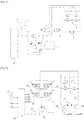
- Fig. 2 is a hydraulic circuit of a swing control apparatus demonstrated for a method for controlling a discharge flow rate of hydraulic pump for construction machine according to an embodiment of the present invention.
- Fig. 3 is a block diagram of a method for controlling a discharge flow rate of hydraulic pump for construction machine according to an embodiment of the present invention.
- Fig. 4 is a flow chart of a method for controlling a discharge flow rate of hydraulic pump for construction machine according to an embodiment of the present invention.
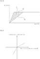
- Fig. 5 is a graph showing characteristic gradients for compensating a discharge flow rate so that the discharge flow rate does not exceed a required flow rated corresponding to an operation amount of a swing operation lever as well as a preset relief pressure of the relief valve according to a method for controlling a discharge flow rate of hydraulic pump for construction machine according to an embodiment of the present invention.
- Fig. 6 is a graph showing gradient correction of a discharge flow rate in swing operation according to a method for controlling a discharge flow rate of hydraulic pump for construction machine according to an embodiment of the present invention.
- a method for controlling discharge flow rate of hydraulic pump for construction machine including a variable displacement hydraulic pump (10); a swing motor (11) that is driven by working oil of a hydraulic pump (10) to revolving an upper swing structure (not shown); a swing operation lever (RCV) including an electric swing operation lever (12); a detection means (13) for detecting an operation amount of the swing operation lever (12); an electric proportional valve (14, 15, 16, 17) for controlling the working oil supplied to the swing motor (11) from the hydraulic pump (10); a pressure sensor (18, 19) for detecting a swing pressure generated in the swing motor (11); and a controller (20) to which the detected signals are inputted from the detection means (13) and the pressure sensor (18, 19), the method comprises; a step (S10) of detecting the operation amount of the swing operation lever (12) and the swing pressure (Pa or Pb) generated in the swing motor (11); a step (S20) of calculating a flow rate required for the swing motor (1
- a slope a in Fig.5 value of swing acceleration to increase a discharge flow rate of the hydraulic pump (10) from swing start as a slope value, when the upper swing structure is to be revolved; a step (S40) of correcting the first gradient value to a second gradient value (e.g. a slope value compensated or corrected by a difference between a preset relief pressure as a reference pressure and the detected pressure in Fig.
- a second gradient value e.g. a slope value compensated or corrected by a difference between a preset relief pressure as a reference pressure and the detected pressure in Fig.
- the method further comprises the step (S60) of discharging the discharge flow rate from the hydraulic pump (10) in response to the swing operation lever if the flow rate corrected by the second gradient is greater than the required flow rate corresponding to the operation amount of the swing operation lever (12), and while controlling the discharge flow of the hydraulic pump (10) in response to the corrected flow rate from the hydraulic pump (10) if the flow rate corrected by the second gradient is smaller than the required flow rate corresponding to the operation amount of the swing operation lever (12).
- the step of correcting the first gradient value to the second gradient value is carried out by correcting or compensating the first gradient value to increase if the reference pressure of the preset relief pressure for the relief valve (21) is greater than the swing pressure detected in the swing motor (11), and while correcting or compensating the first gradient to decrease if the reference pressure of the preset relief pressure is smaller than the swing pressure detected in the swing motor (11).
- the swing motor (11) is driven by the working oil supplied from the hydraulic pump (10) as the electric proportional valve (14, 15, 16, 17) is shifted by the swing operation lever (12), the swing pressure (Pa, Pb) generated in the flow path of the swing motor (11) is detected by the pressure sensor (18, 19) and inputted to the controller (20).
- the first gradient value of the swing acceleration is calculated to increase the discharge flow rate of the hydraulic pump (10) from swing start, when the upper swing structure is to be revolved by driving the swing motor (11). That is, the first gradient is Sref, and the arbitrary reference value of the gradient as a slope can be set experimentally although the optimal slope or gradient varies according to a position or an inertia of the upper working device.
- the second slope value is calculated by taking into account the difference between the swing pressure (Pa or Pb) detected in the swing motor (11) and the reference pressure of the preset relief pressure of the relief valve (21) associated with the swing motor (11).
- a swing flow rate (Qsw) is calculated or compensated by restricting a required flow rate (Qr) corresponding to the value of the second gradient.
- Qsw(t) Qsw(t-1) + S x dT.
- Qsw(t-1) is the previously calculated Qsw
- dT is the sampling time.
- the calculated swing flow rate (Qsw) is compared with the required flow rate (Qr) corresponding to the operation amount of the swing operation lever (12). If Qsw is greater than Qr, it proceeds to S60A, and if Qsw is smaller than Qr, it proceeds to S60B.
- the electrical signal is applied through an output means (20b) of the controller (20) to an regulator (22) for adjusting the swash angle of the hydraulic pump (10), so that Qr is discharged from the hydraulic pump (10).
- the discharge flow rate is optimally restricted or reduced so that only the discharge flow rate required for a torque where the upper swing structure is in swing start is controlled for the swing motor (11), and thus the working oil that returns to the oil tank through the relief valve (21) of the swing motor (11) can be reduced.
- the loss in flow rate that returns through the relief valve can be minimized while securing the swing acceleration of the upper swing structure.
Claims (3)
- Procédé pour commander un débit d'évacuation de pompe hydraulique (10) pour un engin de chantier, comportant une pompe hydraulique à cylindrée variable ; un moteur d'oscillation (11) qui est entraîné par une huile de travail de la pompe hydraulique (10) afin de faire tourner une structure supérieure d'oscillation ; un levier d'actionnement d'oscillation (12) ; un moyen de détection (13) pour détecter une quantité d'actionnement du levier d'actionnement d'oscillation (12) ; une électrovanne proportionnelle (14, 15, 16, 17) pour commander l'huile de travail fournie au moteur d'oscillation (11) par la pompe hydraulique ; un capteur de pression (18, 19) pour détecter une pression d'oscillation générée dans le moteur d'oscillation (11) ; et un dispositif de commande (20) dans lequel les signaux détectés sont introduits à partir du moyen de détection (13) et du capteur de pression (18, 19), le procédé étant caractérisé en ce qu'il comprend :une étape consistant à détecter la quantité d'actionnement du levier d'actionnement d'oscillation et la pression d'oscillation générée dans le moteur d'oscillation ;une étape consistant à calculer un débit requis pour le moteur d'oscillation en réponse à la quantité d'actionnement du levier d'actionnement d'oscillation ; etune étape consistant à calculer une première valeur de gradient d'accélération d'oscillation pour augmenter un débit d'évacuation de la pompe hydraulique depuis le début d'oscillation, lorsque la structure supérieure d'oscillation doit être mise en rotation ;une étape consistant à corriger la première valeur de gradient à une deuxième valeur de gradient en prenant en considération une différence entre la pression d'oscillation et une pression de décharge prédéfinie d'une soupape de décharge (21) en tant que pression de référence ; etune étape consistant à commander le débit d'évacuation de la pompe hydraulique de sorte qu'une augmentation du débit requis soit limitée à un débit correspondant à la deuxième valeur de gradient.
- Procédé de la revendication 1, comprenant en outre une étape de commande du débit d'évacuation de la pompe hydraulique (10) si le débit corrigé par la deuxième valeur de gradient est supérieur au débit requis correspondant à la quantité d'actionnement du levier d'actionnement d'oscillation, tout en commandant le débit d'évacuation de la pompe hydraulique en réponse au débit corrigé si le débit corrigé par la deuxième valeur de gradient est inférieur au débit requis correspondant à la quantité d'actionnement du levier d'actionnement d'oscillation.
- Procédé de la revendication 1, dans lequel l'étape consistant à corriger la première valeur de gradient à la deuxième valeur de gradient est effectuée en compensant la première valeur de gradient de façon à augmenter si la pression de décharge prédéfinie est supérieure à la pression d'oscillation détectée, tout en compensant la première valeur de gradient de façon à diminuer si la pression de décharge prédéfinie est inférieure à la pression d'oscillation détectée.
Applications Claiming Priority (1)
| Application Number | Priority Date | Filing Date | Title |
|---|---|---|---|
| PCT/KR2015/000179 WO2016111392A1 (fr) | 2015-01-08 | 2015-01-08 | Procédé de régulation du débit d'une pompe hydraulique d'un engin de chantier |
Publications (3)
| Publication Number | Publication Date |
|---|---|
| EP3249111A1 EP3249111A1 (fr) | 2017-11-29 |
| EP3249111A4 EP3249111A4 (fr) | 2018-08-29 |
| EP3249111B1 true EP3249111B1 (fr) | 2019-08-14 |
Family
ID=56356074
Family Applications (1)
| Application Number | Title | Priority Date | Filing Date |
|---|---|---|---|
| EP15877113.9A Active EP3249111B1 (fr) | 2015-01-08 | 2015-01-08 | Procédé de régulation du débit d'une pompe hydraulique d'un engin de chantier |
Country Status (4)
| Country | Link |
|---|---|
| US (1) | US20180023270A1 (fr) |
| EP (1) | EP3249111B1 (fr) |
| CN (1) | CN107250462A (fr) |
| WO (1) | WO2016111392A1 (fr) |
Families Citing this family (3)
| Publication number | Priority date | Publication date | Assignee | Title |
|---|---|---|---|---|
| WO2019224879A1 (fr) * | 2018-05-21 | 2019-11-28 | 川崎重工業株式会社 | Système d'entrainement hydraulique pour machine de construction |
| JP7236365B2 (ja) * | 2019-09-20 | 2023-03-09 | 日立建機株式会社 | 建設機械 |
| US11880811B2 (en) | 2021-08-19 | 2024-01-23 | The Toronto-Dominion Bank | System and method for generating data transfer recommendations |
Family Cites Families (12)
| Publication number | Priority date | Publication date | Assignee | Title |
|---|---|---|---|---|
| KR0185429B1 (ko) * | 1994-05-31 | 1999-04-01 | 토니헬샴 | 선회체의 구동제어장치 |
| KR100593512B1 (ko) * | 1999-12-23 | 2006-06-28 | 두산인프라코어 주식회사 | 유압중장비의 선회제어장치 |
| JP2002265187A (ja) * | 2001-03-09 | 2002-09-18 | Hitachi Constr Mach Co Ltd | 旋回制御装置 |
| JP4096900B2 (ja) * | 2004-03-17 | 2008-06-04 | コベルコ建機株式会社 | 作業機械の油圧制御回路 |
| KR101164669B1 (ko) * | 2004-06-17 | 2012-07-11 | 두산인프라코어 주식회사 | 건설중장비의 선회제어장치 및 방법 |
| JP4434159B2 (ja) * | 2006-03-02 | 2010-03-17 | コベルコ建機株式会社 | 作業機械の油圧制御装置 |
| KR101189632B1 (ko) * | 2008-03-31 | 2012-10-11 | 가부시키가이샤 고마쓰 세이사쿠쇼 | 건설 기계의 선회 구동 제어 시스템 |
| JP5391040B2 (ja) * | 2009-11-26 | 2014-01-15 | キャタピラー エス エー アール エル | 作業機械の旋回油圧制御装置 |
| KR101728380B1 (ko) * | 2010-06-24 | 2017-04-19 | 볼보 컨스트럭션 이큅먼트 에이비 | 건설기계의 유압펌프 토출유량 제어방법 |
| US20130125537A1 (en) * | 2010-07-30 | 2013-05-23 | Volvo Construction Equipment Ab | Swirl flow control system for construction equipment and method of controlling the same |
| CN103080566B (zh) * | 2010-09-02 | 2016-02-10 | 沃尔沃建造设备有限公司 | 用于施工设备的液压回路 |
| CN102900122B (zh) * | 2012-11-09 | 2015-05-20 | 中外合资沃得重工(中国)有限公司 | 挖掘机回转液压系统及控制方法 |
-
2015
- 2015-01-08 EP EP15877113.9A patent/EP3249111B1/fr active Active
- 2015-01-08 WO PCT/KR2015/000179 patent/WO2016111392A1/fr active Application Filing
- 2015-01-08 CN CN201580072894.8A patent/CN107250462A/zh active Pending
- 2015-01-08 US US15/542,013 patent/US20180023270A1/en not_active Abandoned
Non-Patent Citations (1)
| Title |
|---|
| None * |
Also Published As
| Publication number | Publication date |
|---|---|
| EP3249111A4 (fr) | 2018-08-29 |
| CN107250462A (zh) | 2017-10-13 |
| EP3249111A1 (fr) | 2017-11-29 |
| US20180023270A1 (en) | 2018-01-25 |
| WO2016111392A1 (fr) | 2016-07-14 |
Similar Documents
| Publication | Publication Date | Title |
|---|---|---|
| US20130125537A1 (en) | Swirl flow control system for construction equipment and method of controlling the same | |
| US9683588B2 (en) | Hydraulic closed circuit system | |
| EP2341191B1 (fr) | Procédé de contrôle de moteur d'oscillation dans un système hydraulique de type à centre ouvert pour excavateur | |
| US9920780B2 (en) | Slewing drive apparatus for construction machine | |
| KR101725617B1 (ko) | 작업 기계의 유압 구동 장치 | |
| WO2016136229A1 (fr) | Système d'entraînement hydraulique pour équipement de construction | |
| EP3249110B1 (fr) | Appareil de réglage d'oscillation pour engins de chantier et son procédé de réglage | |
| EP3099861A1 (fr) | Dispositif de commande de moteur et de pompe et engin de chantier | |
| EP3249111B1 (fr) | Procédé de régulation du débit d'une pompe hydraulique d'un engin de chantier | |
| KR20100129995A (ko) | 건설기계의 선회제어장치 및 선회제어방법 | |
| US9605691B2 (en) | Oil pressure system for wheel loader | |
| KR20160115475A (ko) | 건설기계의 유압 펌프 제어 장치 및 제어 방법, 및 이를 포함하는 건설기계 | |
| US20190111950A1 (en) | Railway vehicle vibration damping device | |
| EP3492664B1 (fr) | Machine de construction | |
| EP3255215B1 (fr) | Appareil de commande de pompe hydraulique pour équipement de construction et procédé de commande associé | |
| JP6619939B2 (ja) | 液圧駆動システム | |
| US11781285B2 (en) | Construction machine | |
| JP4206546B2 (ja) | 油圧ウィンチの制御装置 | |
| JPH0384202A (ja) | 建設機械の油圧駆動装置 | |
| JP2001003903A (ja) | 油圧制御装置 | |
| CN113286950A (zh) | 工程机械的回转驱动装置 | |
| JP2014098453A (ja) | 建設機械の油圧ポンプ制御装置 | |
| JP2013019446A (ja) | 油圧制御弁装置 | |
| JP2007298137A (ja) | 建設機械の油圧装置 | |
| KR20120085598A (ko) | 건설기계의 선회 조작을 위한 전자유압펌프 제어 방법 |
Legal Events
| Date | Code | Title | Description |
|---|---|---|---|
| STAA | Information on the status of an ep patent application or granted ep patent |
Free format text: STATUS: THE INTERNATIONAL PUBLICATION HAS BEEN MADE |
|
| PUAI | Public reference made under article 153(3) epc to a published international application that has entered the european phase |
Free format text: ORIGINAL CODE: 0009012 |
|
| STAA | Information on the status of an ep patent application or granted ep patent |
Free format text: STATUS: REQUEST FOR EXAMINATION WAS MADE |
|
| PUAB | Information related to the publication of an a document modified or deleted |
Free format text: ORIGINAL CODE: 0009199EPPU |
|
| PUAI | Public reference made under article 153(3) epc to a published international application that has entered the european phase |
Free format text: ORIGINAL CODE: 0009012 |
|
| 17P | Request for examination filed |
Effective date: 20170727 |
|
| AK | Designated contracting states |
Kind code of ref document: A1 Designated state(s): AL AT BE BG CH CY CZ DE DK EE ES FI FR GB GR HR HU IE IS IT LI LT LU LV MC MK MT NL NO PL PT RO RS SE SI SK SM TR |
|
| AX | Request for extension of the european patent |
Extension state: BA ME |
|
| DAX | Request for extension of the european patent (deleted) | ||
| A4 | Supplementary search report drawn up and despatched |
Effective date: 20180731 |
|
| RIC1 | Information provided on ipc code assigned before grant |
Ipc: E02F 9/12 20060101AFI20180725BHEP Ipc: E02F 9/20 20060101ALI20180725BHEP Ipc: E02F 9/22 20060101ALI20180725BHEP Ipc: F15B 13/02 20060101ALI20180725BHEP |
|
| GRAP | Despatch of communication of intention to grant a patent |
Free format text: ORIGINAL CODE: EPIDOSNIGR1 |
|
| STAA | Information on the status of an ep patent application or granted ep patent |
Free format text: STATUS: GRANT OF PATENT IS INTENDED |
|
| INTG | Intention to grant announced |
Effective date: 20190308 |
|
| GRAS | Grant fee paid |
Free format text: ORIGINAL CODE: EPIDOSNIGR3 |
|
| GRAA | (expected) grant |
Free format text: ORIGINAL CODE: 0009210 |
|
| STAA | Information on the status of an ep patent application or granted ep patent |
Free format text: STATUS: THE PATENT HAS BEEN GRANTED |
|
| AK | Designated contracting states |
Kind code of ref document: B1 Designated state(s): AL AT BE BG CH CY CZ DE DK EE ES FI FR GB GR HR HU IE IS IT LI LT LU LV MC MK MT NL NO PL PT RO RS SE SI SK SM TR |
|
| REG | Reference to a national code |
Ref country code: GB Ref legal event code: FG4D |
|
| REG | Reference to a national code |
Ref country code: CH Ref legal event code: EP Ref country code: AT Ref legal event code: REF Ref document number: 1167189 Country of ref document: AT Kind code of ref document: T Effective date: 20190815 |
|
| REG | Reference to a national code |
Ref country code: IE Ref legal event code: FG4D |
|
| REG | Reference to a national code |
Ref country code: DE Ref legal event code: R096 Ref document number: 602015036073 Country of ref document: DE |
|
| REG | Reference to a national code |
Ref country code: NL Ref legal event code: MP Effective date: 20190814 |
|
| REG | Reference to a national code |
Ref country code: LT Ref legal event code: MG4D |
|
| PG25 | Lapsed in a contracting state [announced via postgrant information from national office to epo] |
Ref country code: HR Free format text: LAPSE BECAUSE OF FAILURE TO SUBMIT A TRANSLATION OF THE DESCRIPTION OR TO PAY THE FEE WITHIN THE PRESCRIBED TIME-LIMIT Effective date: 20190814 Ref country code: BG Free format text: LAPSE BECAUSE OF FAILURE TO SUBMIT A TRANSLATION OF THE DESCRIPTION OR TO PAY THE FEE WITHIN THE PRESCRIBED TIME-LIMIT Effective date: 20191114 Ref country code: NL Free format text: LAPSE BECAUSE OF FAILURE TO SUBMIT A TRANSLATION OF THE DESCRIPTION OR TO PAY THE FEE WITHIN THE PRESCRIBED TIME-LIMIT Effective date: 20190814 Ref country code: LT Free format text: LAPSE BECAUSE OF FAILURE TO SUBMIT A TRANSLATION OF THE DESCRIPTION OR TO PAY THE FEE WITHIN THE PRESCRIBED TIME-LIMIT Effective date: 20190814 Ref country code: PT Free format text: LAPSE BECAUSE OF FAILURE TO SUBMIT A TRANSLATION OF THE DESCRIPTION OR TO PAY THE FEE WITHIN THE PRESCRIBED TIME-LIMIT Effective date: 20191216 Ref country code: NO Free format text: LAPSE BECAUSE OF FAILURE TO SUBMIT A TRANSLATION OF THE DESCRIPTION OR TO PAY THE FEE WITHIN THE PRESCRIBED TIME-LIMIT Effective date: 20191114 Ref country code: SE Free format text: LAPSE BECAUSE OF FAILURE TO SUBMIT A TRANSLATION OF THE DESCRIPTION OR TO PAY THE FEE WITHIN THE PRESCRIBED TIME-LIMIT Effective date: 20190814 Ref country code: FI Free format text: LAPSE BECAUSE OF FAILURE TO SUBMIT A TRANSLATION OF THE DESCRIPTION OR TO PAY THE FEE WITHIN THE PRESCRIBED TIME-LIMIT Effective date: 20190814 |
|
| REG | Reference to a national code |
Ref country code: AT Ref legal event code: MK05 Ref document number: 1167189 Country of ref document: AT Kind code of ref document: T Effective date: 20190814 |
|
| PG25 | Lapsed in a contracting state [announced via postgrant information from national office to epo] |
Ref country code: RS Free format text: LAPSE BECAUSE OF FAILURE TO SUBMIT A TRANSLATION OF THE DESCRIPTION OR TO PAY THE FEE WITHIN THE PRESCRIBED TIME-LIMIT Effective date: 20190814 Ref country code: IS Free format text: LAPSE BECAUSE OF FAILURE TO SUBMIT A TRANSLATION OF THE DESCRIPTION OR TO PAY THE FEE WITHIN THE PRESCRIBED TIME-LIMIT Effective date: 20191214 Ref country code: GR Free format text: LAPSE BECAUSE OF FAILURE TO SUBMIT A TRANSLATION OF THE DESCRIPTION OR TO PAY THE FEE WITHIN THE PRESCRIBED TIME-LIMIT Effective date: 20191115 Ref country code: ES Free format text: LAPSE BECAUSE OF FAILURE TO SUBMIT A TRANSLATION OF THE DESCRIPTION OR TO PAY THE FEE WITHIN THE PRESCRIBED TIME-LIMIT Effective date: 20190814 Ref country code: AL Free format text: LAPSE BECAUSE OF FAILURE TO SUBMIT A TRANSLATION OF THE DESCRIPTION OR TO PAY THE FEE WITHIN THE PRESCRIBED TIME-LIMIT Effective date: 20190814 Ref country code: LV Free format text: LAPSE BECAUSE OF FAILURE TO SUBMIT A TRANSLATION OF THE DESCRIPTION OR TO PAY THE FEE WITHIN THE PRESCRIBED TIME-LIMIT Effective date: 20190814 |
|
| PG25 | Lapsed in a contracting state [announced via postgrant information from national office to epo] |
Ref country code: TR Free format text: LAPSE BECAUSE OF FAILURE TO SUBMIT A TRANSLATION OF THE DESCRIPTION OR TO PAY THE FEE WITHIN THE PRESCRIBED TIME-LIMIT Effective date: 20190814 |
|
| PG25 | Lapsed in a contracting state [announced via postgrant information from national office to epo] |
Ref country code: DK Free format text: LAPSE BECAUSE OF FAILURE TO SUBMIT A TRANSLATION OF THE DESCRIPTION OR TO PAY THE FEE WITHIN THE PRESCRIBED TIME-LIMIT Effective date: 20190814 Ref country code: EE Free format text: LAPSE BECAUSE OF FAILURE TO SUBMIT A TRANSLATION OF THE DESCRIPTION OR TO PAY THE FEE WITHIN THE PRESCRIBED TIME-LIMIT Effective date: 20190814 Ref country code: AT Free format text: LAPSE BECAUSE OF FAILURE TO SUBMIT A TRANSLATION OF THE DESCRIPTION OR TO PAY THE FEE WITHIN THE PRESCRIBED TIME-LIMIT Effective date: 20190814 Ref country code: RO Free format text: LAPSE BECAUSE OF FAILURE TO SUBMIT A TRANSLATION OF THE DESCRIPTION OR TO PAY THE FEE WITHIN THE PRESCRIBED TIME-LIMIT Effective date: 20190814 Ref country code: IT Free format text: LAPSE BECAUSE OF FAILURE TO SUBMIT A TRANSLATION OF THE DESCRIPTION OR TO PAY THE FEE WITHIN THE PRESCRIBED TIME-LIMIT Effective date: 20190814 Ref country code: PL Free format text: LAPSE BECAUSE OF FAILURE TO SUBMIT A TRANSLATION OF THE DESCRIPTION OR TO PAY THE FEE WITHIN THE PRESCRIBED TIME-LIMIT Effective date: 20190814 |
|
| PG25 | Lapsed in a contracting state [announced via postgrant information from national office to epo] |
Ref country code: SM Free format text: LAPSE BECAUSE OF FAILURE TO SUBMIT A TRANSLATION OF THE DESCRIPTION OR TO PAY THE FEE WITHIN THE PRESCRIBED TIME-LIMIT Effective date: 20190814 Ref country code: IS Free format text: LAPSE BECAUSE OF FAILURE TO SUBMIT A TRANSLATION OF THE DESCRIPTION OR TO PAY THE FEE WITHIN THE PRESCRIBED TIME-LIMIT Effective date: 20200224 Ref country code: SK Free format text: LAPSE BECAUSE OF FAILURE TO SUBMIT A TRANSLATION OF THE DESCRIPTION OR TO PAY THE FEE WITHIN THE PRESCRIBED TIME-LIMIT Effective date: 20190814 Ref country code: CZ Free format text: LAPSE BECAUSE OF FAILURE TO SUBMIT A TRANSLATION OF THE DESCRIPTION OR TO PAY THE FEE WITHIN THE PRESCRIBED TIME-LIMIT Effective date: 20190814 |
|
| REG | Reference to a national code |
Ref country code: DE Ref legal event code: R097 Ref document number: 602015036073 Country of ref document: DE |
|
| PLBE | No opposition filed within time limit |
Free format text: ORIGINAL CODE: 0009261 |
|
| STAA | Information on the status of an ep patent application or granted ep patent |
Free format text: STATUS: NO OPPOSITION FILED WITHIN TIME LIMIT |
|
| PG2D | Information on lapse in contracting state deleted |
Ref country code: IS |
|
| 26N | No opposition filed |
Effective date: 20200603 |
|
| PG25 | Lapsed in a contracting state [announced via postgrant information from national office to epo] |
Ref country code: SI Free format text: LAPSE BECAUSE OF FAILURE TO SUBMIT A TRANSLATION OF THE DESCRIPTION OR TO PAY THE FEE WITHIN THE PRESCRIBED TIME-LIMIT Effective date: 20190814 Ref country code: MC Free format text: LAPSE BECAUSE OF FAILURE TO SUBMIT A TRANSLATION OF THE DESCRIPTION OR TO PAY THE FEE WITHIN THE PRESCRIBED TIME-LIMIT Effective date: 20190814 |
|
| REG | Reference to a national code |
Ref country code: CH Ref legal event code: PL |
|
| GBPC | Gb: european patent ceased through non-payment of renewal fee |
Effective date: 20200108 |
|
| REG | Reference to a national code |
Ref country code: BE Ref legal event code: MM Effective date: 20200131 |
|
| PG25 | Lapsed in a contracting state [announced via postgrant information from national office to epo] |
Ref country code: GB Free format text: LAPSE BECAUSE OF NON-PAYMENT OF DUE FEES Effective date: 20200108 Ref country code: LU Free format text: LAPSE BECAUSE OF NON-PAYMENT OF DUE FEES Effective date: 20200108 |
|
| PG25 | Lapsed in a contracting state [announced via postgrant information from national office to epo] |
Ref country code: LI Free format text: LAPSE BECAUSE OF NON-PAYMENT OF DUE FEES Effective date: 20200131 Ref country code: CH Free format text: LAPSE BECAUSE OF NON-PAYMENT OF DUE FEES Effective date: 20200131 Ref country code: BE Free format text: LAPSE BECAUSE OF NON-PAYMENT OF DUE FEES Effective date: 20200131 |
|
| PG25 | Lapsed in a contracting state [announced via postgrant information from national office to epo] |
Ref country code: IE Free format text: LAPSE BECAUSE OF NON-PAYMENT OF DUE FEES Effective date: 20200108 |
|
| PG25 | Lapsed in a contracting state [announced via postgrant information from national office to epo] |
Ref country code: MT Free format text: LAPSE BECAUSE OF FAILURE TO SUBMIT A TRANSLATION OF THE DESCRIPTION OR TO PAY THE FEE WITHIN THE PRESCRIBED TIME-LIMIT Effective date: 20190814 Ref country code: CY Free format text: LAPSE BECAUSE OF FAILURE TO SUBMIT A TRANSLATION OF THE DESCRIPTION OR TO PAY THE FEE WITHIN THE PRESCRIBED TIME-LIMIT Effective date: 20190814 |
|
| PG25 | Lapsed in a contracting state [announced via postgrant information from national office to epo] |
Ref country code: MK Free format text: LAPSE BECAUSE OF FAILURE TO SUBMIT A TRANSLATION OF THE DESCRIPTION OR TO PAY THE FEE WITHIN THE PRESCRIBED TIME-LIMIT Effective date: 20190814 |
|
| PGFP | Annual fee paid to national office [announced via postgrant information from national office to epo] |
Ref country code: FR Payment date: 20230124 Year of fee payment: 9 |
|
| PGFP | Annual fee paid to national office [announced via postgrant information from national office to epo] |
Ref country code: DE Payment date: 20230127 Year of fee payment: 9 |