EP3249089B1 - Appareil de traitement du linge - Google Patents
Appareil de traitement du linge Download PDFInfo
- Publication number
- EP3249089B1 EP3249089B1 EP16170779.9A EP16170779A EP3249089B1 EP 3249089 B1 EP3249089 B1 EP 3249089B1 EP 16170779 A EP16170779 A EP 16170779A EP 3249089 B1 EP3249089 B1 EP 3249089B1
- Authority
- EP
- European Patent Office
- Prior art keywords
- terminal
- coupled
- control terminal
- control
- sensed voltage
- Prior art date
- Legal status (The legal status is an assumption and is not a legal conclusion. Google has not performed a legal analysis and makes no representation as to the accuracy of the status listed.)
- Active
Links
Images

Classifications
-
- D—TEXTILES; PAPER
- D06—TREATMENT OF TEXTILES OR THE LIKE; LAUNDERING; FLEXIBLE MATERIALS NOT OTHERWISE PROVIDED FOR
- D06F—LAUNDERING, DRYING, IRONING, PRESSING OR FOLDING TEXTILE ARTICLES
- D06F37/00—Details specific to washing machines covered by groups D06F21/00 - D06F25/00
- D06F37/30—Driving arrangements
- D06F37/304—Arrangements or adaptations of electric motors
Definitions
- the present invention relates to the field of electric motors. More particularly, the present invention relates to the monitoring of electric motors of laundry treatment machines, such as laundry washing machines, laundry drying machines and laundry washing/drying machines comprising rotatable drums arranged for causing agitation of articles to be treated.
- laundry treatment machines such as laundry washing machines, laundry drying machines and laundry washing/drying machines comprising rotatable drums arranged for causing agitation of articles to be treated.
- Laundry washing machines, laundry drying machines and laundry washing/drying machines are appliances adapted to treat (e.g ., wash and/or dry) clothes, garments, laundry in general.
- laundry treatment appliances comprise a rotatable drum adapted to receive articles to be treated (e.g ., washed and/or dried) for causing agitation of them during the washing and/or drying operations.
- laundry is dried by circulating hot, dry air within the rotatable drum containing the laundry.
- the drum is made to rotate in order to cause agitation of the laundry, which repeatedly tumble with the drum while being invested by the drying air flow.
- laundry treatment appliances are provided with drums configured to rotate in both directions. In this way, the agitation of the laundry contained inside the drum is improved, avoiding that laundry balls up.
- PSCM Permanent Split Capacitor Motor
- a PSCM is a particularly reliable single phase motor that need no starting mechanism, and so it can be reversed easily. In this way, the drum can be made to rapidly switch from the clockwise rotation to the counterclockwise rotation (and viceversa ).
- US 5 237 256 A discloses a control for an automatic washing machine with a reversing permanent split capacitor (PSC) drive motor.
- PSC permanent split capacitor
- Such motor drives a spin basket in one direction during a spin operation of the washing machine, and it is also coupled to an agitator for driving the agitator in clockwise and counterclockwise directions
- Separate ferrite core sensors surround each of two PSC motor windings. A sense winding is threaded through both sensors.
- a brief output voltage is generated whenever the alternating current in either PSC motor winding passes through a zero-crossing and when the sense winding is wound with proper mutual polarity, an output voltage is generated in response to zero-crossings of a brief, residual alternating current which flows in both PSC motor windings and the capacitor when the rotating PSC motor is cycled OFF.
- the circuitry in combination with the sensors, samples the leading or lagging phase angle of the PSC motor auxiliary or main winding, respectively, at a sample rate of two-times the line frequency when the PSC motor is ON.
- the raw PSC motor phase data is used in microcomputer programs to compute motor start time or load torque dither.
- This computed information and the PSC motor braking data is used by other software programs to automatically control various functions of the washing machine such as the fill water level and agitator stroke angle; to control events in an operational sequence such as the duration of the agitation and spin operations; and to provide diagnostic information such as spin off-balance detection.
- AC electric motors for laundry treatment appliances such as the PSCM motor
- the motor load i.e., the mechanical resistance against which the PSCM motor acts for rotating.
- the motor have to respond by developing an increasing torque, causing a corresponding increase in the motor current.
- the load of the AC electric motor becomes excessively high (for example because of an excessive friction due to dryer damage)
- the motor current increases to such an extent to cause overheating.
- This issue is particularly dangerous in case the motor load is so high to cause the AC electric motor to block ("locked rotor condition"). Indeed, in this latter case, the overheating may be so high to cause permanent damage to the AC electric motor itself.
- thermal protection systems i.e ., circuits that are configured to sense the temperature of the AC electric motors and turn off the latter when the sensed temperature exceeds a corresponding safe threshold, in order to avoid that the AC electric motor is damaged.
- thermal protection systems for motors are expensive, and require dedicated temperature sensors.
- patent US 6,795,284 discloses a device for stopping the motor when the load on the motor exceeds a predetermined value. It comprises means transforming the voltage variation at the phase-shifting capacitor terminals corresponding to a specific torque variation into a selected voltage variation whatever the maximum torque developed, means comparing the transformed voltage with a reference voltage and means for stopping the motor when the transformed voltage is less than the reference voltage.
- the aim of the present invention is therefore to provide an efficient and simple way to monitor the load of a PSCM configured to rotate in both directions, which is able to detect overload condition in order to prevent any locked rotor condition occurrence.
- An aspect of the present invention proposes a laundry treatment appliance.
- the laundry treatment appliance further comprises a cabinet and a drum rotatably accommodated within said cabinet for housing laundry to be treated.
- the laundry treatment appliance further comprises a permanent split capacitor motor selectively operable to rotate the drum clockwise and counterclockwise.
- the permanent split capacitor motor is configured to be supplied by a supply voltage provided across a first supply terminal and a second supply terminal of an AC power supply.
- the permanent split capacitor motor comprises a main terminal, a first control terminal, and a second control terminal. The main terminal is coupled with the first supply terminal.
- the laundry treatment appliance further comprises a switching apparatus configured to selectively couple:
- the laundry treatment appliance further comprises a voltage sensing unit configured to sense the voltage at the first control terminal to produce a corresponding first sensed voltage and to sense the voltage at the second control terminal to produce a corresponding second sensed voltage.
- the laundry treatment appliance further comprises a control unit configured to assess an overload condition of the drum based on:
- control unit is configured to assess the overload condition of the drum based on the amplitude of:
- control unit is configured to assess the overload condition of the drum based on the assessment of an abrupt decreasing of the amplitude of:
- control unit is configured to assess the overload condition of the drum when:
- control unit is configured to assess the overload condition of the drum based on the RMS of:
- control unit is configured quantify the actual load of the permanent split capacitor motor based on a predetermined relationship between the torque developed by the permanent split capacitor motor and:
- control unit is configured to turn off the permanent split capacitor motor as soon as an overload condition of the drum is assessed.
- control unit is configured to turn off the permanent split capacitor motor after a predetermined period from the overload condition assessment.
- the switching apparatus comprises a first TRIAC having a first conduction terminal connected to the first control terminal and a second conduction terminal connected to the second supply terminal, and a second TRIAC having a first conduction terminal connected to the second control terminal and a second conduction terminal connected to the second supply terminal.
- the switching apparatus further comprises a driving unit coupled with control terminals of the first TRIAC and of the second TRIAC for:
- the permanent split capacitor motor comprises:
- the laundry treatment appliance is:
- the drum is configured to house laundry to be washed and/or dried.
- control unit is further configured to quantify a laundry load component of the actual load of the permanent split capacitor motor based on a further predetermined relationship between the torque developed by the permanent split capacitor motor and at least one among:
- said control unit is configured to quantify said laundry load component based on a comparison between:
- the switching apparatus comprises:
- the concepts of the present invention may be applied to any laundry treatment appliance comprising a PSCM motor configured to rotate both clockwise and counterclockwise, such as laundry washing machines, laundry drying machines and laundry washing/drying machines.
- a PSCM motor configured to rotate both clockwise and counterclockwise
- laundry washing machines laundry drying machines
- laundry washing/drying machines laundry washing/drying machines
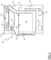
- the laundry drying machine which is identified by reference 100, comprises a laundry treatment chamber 105 including a drum 107 rotatably mounted inside the machine casing or cabinet 110 of the laundry drying machine 100 for accommodating the laundry to be dried.
- the drum 107 is a generically cylindrical body, for example made of stainless steel, open at the ends thereof.
- the cabinet 110 is generically a parallelepiped in shape, and has a front wall, two side walls, a rear wall, a basement and a top.
- the front wall is provided with an opening for accessing the laundry treatment chamber 105 , and particularly a front end of the drum 107 .
- the front wall is further provided with a door 115 for closing the opening.
- the top closes the cabinet 110 from above, and may also define a worktop.
- Drying air is typically caused to flow through the laundry treatment chamber 105 , and therefore through the drum 107 where the laundry to be dried is contained, and is caused to tumble by the drum 107 rotation. After exiting the laundry treatment chamber 105 , the flow of moisture-laden drying air passes through a moisture condensing system, where the humid, moisture-laden drying air is (at least partially) dried, dehydrated, and the dehydrated air flow is then heated and caused to pass again through the laundry treatment chamber 105 , repeating the cycle.
- Reference numeral 120 denotes a compressor of the heat pump forming the moisture condensing system for the moisture-laden drying air
- reference numeral 125 denotes a first heat exchanger, which in the example here considered forms the heat pump evaporator for cooling the drying air and heating the refrigerant
- reference numeral 130 denotes a second heat exchanger, which in the example here considered forms the heat pump condenser for heating the drying air and cooling the refrigerant
- reference numeral 135 denotes expansion means (e.g ., capillary tube, expansion valve) between the evaporator 125 and the condenser 130 of the heat pump
- the dashed lines 140 denote the heat pump refrigerant fluid circuit.
- the compressor 120 , the first heat exchanger 125 , the expansion means 135 and the second heat exchanger 130 form a refrigerant circuit of the heat pump, which is subdivided into a high pressure portion and a low pressure portion: the high pressure portion extends from the outlet of the compressor 120 via the first heat exchanger 125 to the inlet of the expansion means 135 , whereas the low pressure portion extends from the outlet of the expansion means 135 via the second heat exchanger 130 to the inlet of the compressor 120 .
- the first heat exchanger 125 acts as an evaporator
- the second heat exchanger 130 acts as a condenser.
- Reference numeral 145 denotes a drying-air recirculation path.
- Reference numeral 150 denotes a drying-air recirculation fan, which promotes the recirculation of the drying air in the laundry treatment chamber 105 and the drying-air recirculation path 145 .
- Reference numeral 155 denotes a Joule-effect drying air heater, for example one (or, possibly, more than one) electric resistor that is provided in the drying-air recirculation path 145 for boosting the drying air heating and arranged downstream the second heat exchanger 130 .
- the heat pump used as a means for condensing the moisture contained in the drying air returning from the laundry treatment chamber 105 is also able to heat up the drying air after it has been de-humidified (the condenser 130 downstream the evaporator 115 has such a function).
- the recirculation fan 150 is a variable-speed fan.
- the cabinet 110 comprises a drum motor 160 for rotating the drum 107 .
- the drum motor 160 is housed in the basement of the cabinet 110 and is coupled with the drum 107 by means of a belt transmission 165 . Similar considerations apply to direct-drive arrangements, in which the motor 160 is coaxially mounted with respect to the drum 107 rotation axis.
- the drum motor 160 is a bidirectional PSCM, i.e ., a PSCM configured to rotate both clockwise and counterclockwise.
- the PSCM 160 comprises a first winding 210 , a second winding 220 and a capacitor 230 .
- the first winding 210 has a first terminal connected to a main terminal 235 of the PSCM 160 , and a second terminal connected to a first control terminal 240 of the PSCM 160 .
- the second winding 220 has a first terminal connected to the main terminal 235 , and a second terminal connected to a second control terminal 245 of the PSCM 160 .
- the capacitor 230 comprises a first terminal connected to the first control terminal 240 and a second terminal connected to the second control terminal 245 .
- the PSCM 160 is supplied by means of an AC voltage Vac developed across a line terminal 250 and a neutral terminal 255 of an AC power supply, such as the mains voltage power supply.
- the main terminal 235 of the PSCM 160 is connected to the line terminal 250 of the AC power supply, while the first control terminal 240 and the second control terminal 245 are configured to be mutually exclusively coupled to the neutral terminal 255 of the AC power supply based on the desired rotation direction of the PSCM 160 .
- the PSCM 160 rotates clockwise, while, when the second control terminal 245 is coupled with the neutral terminal 255 of the AC power supply, the PSCM 160 rotates counterclockwise (similar considerations apply in case the two rotation directions are exchanged).
- the PSCM 160 operation is controlled by means of a motor control system 260 , for example located on a dedicated electronic board inside the laundry drying machine 100 (similar considerations apply if the motor control system is directly located in the main electronic board of the laundry drying machine 100 ).
- the motor control system 260 comprises two TRIACs 262, 264 (TRIode for Alternating Current), two driver units 266, 268, two voltage sensing units 270, 272, and a control unit 280, such as a microcontroller or a microprocessor.
- the TRIAC 262 has a first conduction terminal connected to the first control terminal 240 of the PSCM 160, a second conduction terminal connected to the neutral terminal 255 of the AC power supply, and a control terminal connected to an output terminal of the driver unit 266 .
- the TRIAC 264 has a first conduction terminal connected to the second control terminal 245 of the PSCM 160 , a second conduction terminal connected to the neutral terminal 255 of the AC power supply, and a control terminal connected to an output terminal of the driver unit 268 .
- the driver unit 266 has an input terminal coupled with the control unit 280 for receiving a driving signal CK and an output terminal coupled with the control terminal of the TRIAC 262 for providing TRIAC triggering pulses based on the driving signal CK.
- the driver unit 268 has an input terminal coupled with the control unit 280 for receiving a driving signal CCK and an output terminal coupled with the control terminal of the TRIAC 264 for providing TRIAC triggering pulses based on the driving signal CCK.
- the driving signals CK and CCK are digital signals capable of taking a high value and a low value, and the driver units 266, 268 are configured to generate TRIAC triggering pulses when the corresponding driving signal CK or CCK is at the high value.
- driver units 266, 268 are configured to generate TRIAC triggering pulses when the corresponding driving signal CK or CCK is at the low value, or the driving signals CK and CCK are analog signals.
- the concepts of the present invention apply also in case a single driver unit is provided, configured to provide triggering signals to both the TRIACs 262, 264.
- the control unit 280 sets the driving signal CK to the high value, while sets the driving signal CCK to the low value.
- the driver unit 266 generates triggering pulses to activate the TRIAC 262, while the driver unit 268 not.
- the TRIAC 262 is turned on, coupling the first control terminal 240 of the PSCM 160 to the neutral terminal 255 of the AC power supply, while the TRIAC 264 is turned off, insulating the second control terminal 245 of the PSCM 160 from the neutral terminal 255 of the AC power supply.
- the control unit 280 sets the driving signal CCK to the high value, while sets the driving signal CK to the low value.
- the driver unit 268 generates triggering pulses to activate the TRIAC 264, while the driver unit 266 not.
- the TRIAC 264 is turned on, coupling the second control terminal 245 of the PSCM 160 to the neutral terminal 255 of the AC power supply, while the TRIAC 262 is turned off, insulating the first control terminal 240 of the PSCM 160 from the neutral terminal 255 of the AC power supply.
- the voltage sensing unit 270 has an input terminal coupled with the first control terminal 240 of the PSCM 160 and an output terminal coupled with the control unit 280 for providing a sensed voltage signal S1 corresponding to the voltage at the first control terminal 240 of the PSCM 160.
- the voltage sensing unit 272 has an input terminal coupled with the second control terminal 242 of the PSCM 160 and an output terminal coupled with the control unit 280 for providing a sensed voltage signal S2 corresponding to the voltage at the second control terminal 242 of the PSCM 160 . Similar considerations apply if a single sensing unit is provided adapted to sense both the voltage at the first control terminal 240 and the voltage at the second control terminal 242 .
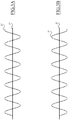
- Figure 3A is a diagram showing an example of how the sensed voltage signals S1 and S2 generated by the voltage sensing units 270, 272 evolve in time in case the PSCM 160 is driven to rotate clockwise.
- the electronic board 260 wherein the motor control system is located is preferably supplied with a non-insulated power supply, so as to simplify the electronic board architecture.
- the TRIAC 262 is driven to be turned on, while the TRIAC 264 is off, so that the first control terminal 240 of the PSCM 160 is connected to the neutral terminal 255 of the AC power supply through the TRIAC 262 while the second control terminal 245 of the PSCM 160 is insulated from the neutral terminal 255 .
- the sensed voltage signal S1 is clamped to the voltage at the neutral terminal 255, while the sensed voltage signal S2 oscillates following (with a phase delay) the AC voltage Vac developed across the line terminal 250 and the neutral terminal 255 of the AC power supply (not illustrated in figure).
- Figure 3B is a diagram showing an example of how the sensed voltage signals S1 and S2 generated by the voltage sensing units 270, 272 evolve in time in case the PSCM 160 is driven to rotate counterclockwise.
- the TRIAC 264 is driven to be turned on, while the TRIAC 262 is off, so that the second control terminal 245 of the PSCM 160 is connected to the neutral terminal 255 of the AC power supply through the TRIAC 264 while the first control terminal 240 of the PSCM 160 is insulated from the neutral terminal 255 .
- the sensed voltage signal S2 is clamped to the voltage at the neutral terminal 255 , while the sensed voltage signal S1 oscillates following (with a phase delay) the AC voltage Vac developed across the line terminal 250 and the neutral terminal 255 of the AC power supply (not illustrated in figure).
- Applicant has found that a relationship occurs between the actual load of the PSCM 160 (in term of torque developed by the PSCM 160 ) and the amplitude of the voltage at the control terminal of the PSCM 160 which is actually disconnected from the neutral terminal 255 of the AC power supply.
- control unit 280 is configured to monitor the load of the PSCM 160 based on:
- Applicant has found that as the torque developed by the PSCM 160 increases, the amplitude of the voltage at the control terminal of the PSCM 160 which is actually disconnected from the neutral terminal 255 of the AC power supply correspondingly decreases. By observing the way such amplitude decreases as the torque developed by the PSCM 160 increases, Applicant has found that an abrupt amplitude decreasing can be observed at an overload condition of the drum 107 occurring before the load of the PSCM 160 is so high to cause the latter to enter in a locked rotor condition.
- control unit 280 is configured to quantify the actual load of the PSCM 160 by measuring the amplitude of the voltage at the control terminal of the PSCM 160 which is actually disconnected from the neutral terminal 255 of the AC power supply, and to assess the occurrence of an overload condition of the drum 107 by identifying possible abrupt amplitude decreasing in the measured voltage.
- control unit 280 is configured to calculate the Root Mean Square (RMS) of the sensed voltage S1 (when the PSCM 160 is driven to rotate counterclockwise) or of the sensed voltage S2 (when the PSCM 160 is driven to rotate clockwise) and to quantify the actual load of the PSCM 160 and to assess the occurrence of an overload condition of the drum 107 based on the calculated RMS.
- RMS Root Mean Square
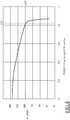
- Figure 4 is a diagram showing a curve corresponding to the RMS of the sensed voltage S1 versus the torque developed by the PSCM 160 according to the exemplary table reported above.
- control unit 280 is configured to quantify the actual load of the PSCM 160 based on a predetermined relationship between the torque developed by the PSCM 160 and the RMS of the sensed voltage S1 (if the PSCM 160 is driven to rotate counterclockwise) or the RMS of the sensed voltage S2 (if the PSCM 160 is driven to rotate clockwise), like the relationship depicted in the exemplary table reported above.
- a predetermined relationship may be calculated as a result of measuring operations carried out during the appliance manufacturing.
- control unit 280 is configured to assess the occurrence of an overload condition of the drum 107 as soon as the RMS of the sensed voltage S1 or S2 falls below an overload threshold OTH indicative of the overload condition and corresponding to the torque threshold TTH.
- control unit 280 may safely turn off the PSCM 160 ( e.g ., by setting both the driving signals CK and CCK to the low value) before the locked condition occurs, avoiding the need of a dedicated thermal protection circuit.
- control unit 208 may be designed to turn off the PSCM 160 (e.g ., by setting both the driving signals CK and CCK to the low value) after a predetermined (safe) period from an overload condition assessment.
- the overload condition which triggers the turning off of the PSCM 160 corresponds to a torque threshold TTH between 0,8 and 0,9 N ⁇ m, and to an overload threshold OTH of about 200 RMS.
- the rotor locked condition occurs when the RMS of the sensed voltage S1 is decreased down to 55,9.
- control unit 280 is configured to assess the occurrence of an overload condition of the drum 107 as soon as the RMS of the sensed voltage S1 or S2 is subjected to an abrupt fall, for example by exploiting a known slope detection procedure.
- control unit 280 is configured to quantify the actual load of the PSCM 160 and to assess the occurrence of an overload condition of the drum 107 by monitoring the peak amplitude of the sensed voltages S1 , S2 (such as for example by exploiting a peak detection procedure) instead of the RMS thereof.
- control unit 280 is further configured to quantify the component of the actual load of the PSCM 160 due to the laundry accommodated in the drum 107 (hereinafter, "laundry load component"). It is underlined that the laundry load component depends on the amount of laundry accommodated in the drum 107 as well as on the amount of water impregnating the laundry itself.
- control unit 280 is configured to quantify said laundry load component based on at least one among the calculated RMS of the sensed voltage(s) S1 and/or S2 when the drum 107 is not in an overload condition ( e.g ., as long as the torque developed by the PSCM 160 is lower than the torque threshold TTH ) .
- control unit 280 is configured to quantify said laundry load component based on a predetermined relationships between the torque developed by the PSCM 160 and the RMS of the sensed voltage S1 (if the PSCM 160 is driven to rotate counterclockwise) or the RMS of the sensed voltage S2 (if the PSCM 160 is driven to rotate clockwise).
- a more precise assessment of the laundry load component is carried out by comparing the RMS of the sensed voltage S1 (when the PSCM 160 is driven to rotate counterclockwise) with the RMS of the sensed voltage S2 (when the PSCM 160 is driven to rotate clockwise).
- the PSCM 160 behavior is influenced by its rotation direction, being usually mounted coaxially with a vent (not illustrated) having a preferred rotation direction.
- TRIACs different switching devices are used to selectively couple the first control terminal 240 and the second control terminal 245 of the PSCM 160 to the neutral terminal 255 , such as for example power transistors or relays.
- the concepts of the present invention may be applied to different type of laundry drying machines, such as condenser laundry machines of the type comprising an air-air exchanger and an heating resistor, as well as venting laundry machines having an open ventilation circuit.
Landscapes
- Engineering & Computer Science (AREA)
- Textile Engineering (AREA)
- Control Of Washing Machine And Dryer (AREA)
Claims (14)
- Appareil de traitement de linge (100), comprenant:- une cuve (110) ;- un tambour (107) logé avec faculté de rotation dans ladite cuve destiné à recevoir le linge à traiter ;- un moteur à condensateur permanent (160) configuré pour être alimenté par une tension d'alimentation fournie entre une première borne d'alimentation (250) et une seconde borne d'alimentation (255) d'une alimentation électrique en C.A., le moteur à condensateur permanent comprenant une borne principale (235), une première borne de commande (240), et une seconde borne de commande (245), la borne principale étant couplée à la première borne d'alimentation :
caractérisé en ce que le moteur à condensateur permanent (160) est actionnable sélectivement pour faire tourner le tambour dans les sens horaire et anti-horaire et en ce que l'appareil de traitement de linge comprend en outre :- un appareil de commutation (262, 264, 266, 268) configuré pour coupler sélectivement :- la première borne de commande à la seconde borne d'alimentation, tout en découplant la seconde borne de commande de la seconde borne d'alimentation, afin de faire tourner le tambour dans le sens horaire, ou- la seconde borne de commande à la seconde borne d'alimentation, tout en découplant la première borne de commande de la seconde borne d'alimentation, pour faire tourner le tambour dans le sens anti-horaire ;- une unité de détection de tension (270, 272) configurée pour détecter la tension à la première borne de commande pour produire une première tension détectée correspondante et détecter la tension à la seconde borne de commande pour produire une seconde tension détectée correspondante ;- une unité de commande (280) configurée pour évaluer un état de surcharge du tambour en fonction dea) la première tension détectée quand la seconde borne de commande est couplée à la seconde borne d'alimentation, etb) la seconde tension détectée quand la première borne de commande est couplée à la seconde borne d'alimentation. - Appareil de traitement de linge selon la revendication 1, dans lequel l'unité de commande (280) est configurée pour évaluer l'état de surcharge du tambour en fonction de l'amplitude de :- la première tension détectée quand la seconde borne de commande est couplée à la seconde borne d'alimentation, et- la seconde tension détectée quand la première borne de commande est couplée à la seconde borne d'alimentation.
- Appareil de traitement de linge selon la revendication 1 ou 2, dans lequel l'unité de commande (280) est configurée pour évaluer l'état de surcharge du tambour en fonction de l'évaluation d'une chute soudaine de l'amplitude de :- la première tension détectée quand la seconde borne de commande est couplée à la seconde borne d'alimentation, et- la seconde tension détectée quand la première borne de commande est couplée à la seconde borne d'alimentation.
- Appareil de traitement de linge selon l'une quelconque des revendications précédentes, dans lequel l'unité de commande (280) est configurée pour évaluer l'état de surcharge du tambour quand :- la première tension détectée chute en dessous d'un seuil de surcharge quand la seconde borne de commande est couplée à la seconde borne d'alimentation, et- la seconde tension détectée chute en dessous du seuil de surcharge quand la première borne de commande est couplée à la seconde borne d'alimentation.
- Appareil de traitement de linge selon l'une quelconque des revendications précédentes, dans lequel l'unité de commande (280) est configurée pour évaluer l'état de surcharge du tambour en fonction de la valeur efficace de :- la première tension détectée quand la seconde borne de commande est couplée à la seconde borne d'alimentation, et- la seconde tension détectée quand la première borne de commande est couplée à la seconde borne d'alimentation.
- Appareil de traitement de linge selon l'une quelconque des revendications précédentes, dans lequel l'unité de commande (280) est configurée pour quantifier la charge réelle du moteur à condensateur permanent en fonction d'une relation prédéterminée entre le couple développé par le moteur à condensateur permanent et :- l'amplitude de la première tension détectée quand la seconde borne de commande est couplée à la seconde borne d'alimentation, et- l'amplitude de la seconde tension détectée quand la première borne de commande est couplée à la seconde borne d'alimentation.
- Appareil de traitement de linge selon l'une quelconque des revendications précédentes, dans lequel l'unité de commande est configurée pour arrêter le moteur à condensateur permanent :- dès qu'un état de surcharge du tambour est évalué ou- après une période prédéterminée à compter de l'évaluation de l'état de surcharge.
- Appareil de traitement de linge selon l'une quelconque des revendications précédentes, dans lequel l'appareil de commutation comprend :- un premier TRIAC (262) présentant une première borne de conduction connectée à la première borne de commande et une seconde borne de conduction connectée à la seconde borne d'alimentation ;- un second TRIAC (264) présentant une première borne de conduction connectée à la seconde borne de commande et une seconde borne de conduction connectée à la seconde borne d'alimentation.
- Appareil de traitement de linge selon la revendication 8, dans lequel l'appareil de commutation comprend en outre une unité d'entraînement (266, 268) couplée à des bornes de commande du premier TRIAC (262) et du second TRIAC (264) pour :- activer le premier TRIAC (262) et désactiver le second TRIAC (264) afin de faire tourner le tambour dans le sens horaire, ou- désactiver le premier TRIAC (262) et activer le second TRIAC (264) afin de faire tourner le tambour dans le sens anti-horaire.
- Appareil de traitement de linge selon l'une quelconque des revendications précédentes, dans lequel le moteur à condensateur permanent comprend :- un premier enroulement (210) présentant une première borne couplée à la borne principale et une seconde borne couplée à la première borne de commande ;- un second enroulement (220) présentant une première borne couplée à la borne principale et une seconde borne couplée à la seconde borne de commande, et- un condensateur (230) présentant une première borne couplée à la première borne de commande et une seconde borne couplée à la seconde borne de commande.
- Appareil de traitement de linge selon l'une quelconque des revendications précédentes, l'appareil de traitement de linge étant :- une machine à laver le linge ;- une machine à sécher le linge, ou- une machine à laver/sécher le linge,le tambour étant configuré pour recevoir le linge à laver et/ou sécher.
- Appareil de traitement de linge selon la revendication 6 et l'une quelconque des revendications 1 à 5 quand elle dépend de la revendication 6, dans lequel l'unité de commande (280) est configurée en outre pour quantifier une composante de charge de linge de la charge réelle du moteur à condensateur permanent en fonction d'une autre relation prédéterminée entre le couple développé par le moteur à condensateur permanent et au moins l'une de :- l'amplitude de la première tension détectée quand la seconde borne de commande est couplée à la seconde borne d'alimentation, et- l'amplitude de la seconde tension détectée quand la première borne de commande est couplée à la seconde borne d'alimentation,quand le tambour (107) n'est pas en état de surcharge.
- Appareil de traitement de linge selon la revendication 13, dans lequel ladite unité de commande (280) est configurée pour quantifier ladite composante de charge de linge en fonction d'une comparaison entre- l'amplitude de la première tension détectée quand la seconde borne de commande est couplée à la seconde borne d'alimentation, et- l'amplitude de la seconde tension détectée quand la première borne de commande est couplée à la seconde borne d'alimentation.
- Appareil de traitement de linge selon l'une quelconque des revendications 1 à 7, dans lequel l'appareil de commutation comprend :- un premier relais présentant une première borne de conduction connectée à la première borne de commande et une seconde borne de conduction connectée à la seconde borne d'alimentation ;- un second relais présentant une première borne de conduction connectée à la seconde borne de commande et une seconde borne de conduction connectée à la seconde borne d'alimentation.
Priority Applications (1)
| Application Number | Priority Date | Filing Date | Title |
|---|---|---|---|
| EP16170779.9A EP3249089B1 (fr) | 2016-05-23 | 2016-05-23 | Appareil de traitement du linge |
Applications Claiming Priority (1)
| Application Number | Priority Date | Filing Date | Title |
|---|---|---|---|
| EP16170779.9A EP3249089B1 (fr) | 2016-05-23 | 2016-05-23 | Appareil de traitement du linge |
Publications (2)
| Publication Number | Publication Date |
|---|---|
| EP3249089A1 EP3249089A1 (fr) | 2017-11-29 |
| EP3249089B1 true EP3249089B1 (fr) | 2019-07-10 |
Family
ID=56068761
Family Applications (1)
| Application Number | Title | Priority Date | Filing Date |
|---|---|---|---|
| EP16170779.9A Active EP3249089B1 (fr) | 2016-05-23 | 2016-05-23 | Appareil de traitement du linge |
Country Status (1)
| Country | Link |
|---|---|
| EP (1) | EP3249089B1 (fr) |
Families Citing this family (1)
| Publication number | Priority date | Publication date | Assignee | Title |
|---|---|---|---|---|
| US11387752B2 (en) * | 2017-09-01 | 2022-07-12 | Electrolux Appliances Aktiebolag | Washing machine for washing articles equipped with an electric drive unit to operate electric motors |
Family Cites Families (3)
| Publication number | Priority date | Publication date | Assignee | Title |
|---|---|---|---|---|
| US5237256A (en) * | 1989-08-11 | 1993-08-17 | Whirlpool Corporation | Electronic control for an automatic washing machine with a reversing PSC motor |
| FR2806850B1 (fr) | 2000-03-27 | 2002-05-24 | Somfy | Dispositif d'arret d'un moteur asynchrone monophase a condensateur de dephasage |
| EP2703539B1 (fr) * | 2012-09-03 | 2020-03-18 | Electrolux Home Products Corporation N.V. | Procédé pour commander le moteur asynchrone d'une machine de traitement du linge et machine de traitement de linge |
-
2016
- 2016-05-23 EP EP16170779.9A patent/EP3249089B1/fr active Active
Non-Patent Citations (1)
| Title |
|---|
| None * |
Also Published As
| Publication number | Publication date |
|---|---|
| EP3249089A1 (fr) | 2017-11-29 |
Similar Documents
| Publication | Publication Date | Title |
|---|---|---|
| AU2014253302B2 (en) | Method for controlling a motor of a laundry dryer | |
| US5564831A (en) | Method and apparatus for detecting the temperature of an environment | |
| US5166592A (en) | Motor diagnostics and electronic control for a clothes dryer | |
| US2885789A (en) | Apparatus for drying fabrics | |
| JP2022517005A (ja) | インダクションヒーターを有する洗濯装置 | |
| AU2016204990B2 (en) | Method of operation of a heat pump drying and/or washing appliance and heat pump drying and/or washing appliance | |
| WO2014001114A1 (fr) | Machine à traiter du linge ou de la vaisselle | |
| AU2017423442B2 (en) | Method to control operation of a laundry dryer | |
| EP3249089B1 (fr) | Appareil de traitement du linge | |
| US3510957A (en) | Dryer control system | |
| US2869247A (en) | Control system for clothes dryers | |
| US3229380A (en) | Automatic dryer control circuit | |
| EP2610401B1 (fr) | Système et procédé pour estimer la charge de linge dans un sèche-linge à tambour rotatif | |
| EP2610388A1 (fr) | Sèche-linge et son procédé de contrôle | |
| EP3314051B1 (fr) | Régulation d'alimentation en courant dans des machines de traitement du linge ou des lave-vaisselle | |
| US20060218816A1 (en) | Dryer heat modulation with solid state motor switch | |
| CN115698417A (zh) | 用于操作配备有热泵系统的衣物干燥机的方法及实施所述方法的衣物干燥机 | |
| EP3314050A1 (fr) | Régulation d'alimentation en courant dans des machines de traitement du linge ou des lave-vaisselle | |
| EP2604751A1 (fr) | Machine de séchage du linge et procédé de commande correspondant | |
| JP4525472B2 (ja) | 洗濯乾燥機用制御装置 | |
| EP2770101B1 (fr) | Machine de blanchisserie | |
| WO2021244876A1 (fr) | Procédé de fonctionnement d'un sèche-linge équipé d'un système de pompe à chaleur et sèche-linge mettant en œuvre ledit procédé | |
| EP2638196B1 (fr) | Machine à laver séchante comprenant un relais qui détermine la direction de rotation du moteur | |
| JP2009101222A (ja) | 洗濯乾燥機 | |
| EP3314052A1 (fr) | Régulation d'alimentation en courant dans des machines de traitement du linge ou des lave-vaisselle |
Legal Events
| Date | Code | Title | Description |
|---|---|---|---|
| PUAI | Public reference made under article 153(3) epc to a published international application that has entered the european phase |
Free format text: ORIGINAL CODE: 0009012 |
|
| STAA | Information on the status of an ep patent application or granted ep patent |
Free format text: STATUS: THE APPLICATION HAS BEEN PUBLISHED |
|
| AK | Designated contracting states |
Kind code of ref document: A1 Designated state(s): AL AT BE BG CH CY CZ DE DK EE ES FI FR GB GR HR HU IE IS IT LI LT LU LV MC MK MT NL NO PL PT RO RS SE SI SK SM TR |
|
| AX | Request for extension of the european patent |
Extension state: BA ME |
|
| STAA | Information on the status of an ep patent application or granted ep patent |
Free format text: STATUS: REQUEST FOR EXAMINATION WAS MADE |
|
| 17P | Request for examination filed |
Effective date: 20180529 |
|
| RBV | Designated contracting states (corrected) |
Designated state(s): AL AT BE BG CH CY CZ DE DK EE ES FI FR GB GR HR HU IE IS IT LI LT LU LV MC MK MT NL NO PL PT RO RS SE SI SK SM TR |
|
| RIC1 | Information provided on ipc code assigned before grant |
Ipc: D06F 37/30 20060101AFI20180803BHEP |
|
| GRAP | Despatch of communication of intention to grant a patent |
Free format text: ORIGINAL CODE: EPIDOSNIGR1 |
|
| STAA | Information on the status of an ep patent application or granted ep patent |
Free format text: STATUS: GRANT OF PATENT IS INTENDED |
|
| INTG | Intention to grant announced |
Effective date: 20180914 |
|
| GRAJ | Information related to disapproval of communication of intention to grant by the applicant or resumption of examination proceedings by the epo deleted |
Free format text: ORIGINAL CODE: EPIDOSDIGR1 |
|
| STAA | Information on the status of an ep patent application or granted ep patent |
Free format text: STATUS: REQUEST FOR EXAMINATION WAS MADE |
|
| GRAP | Despatch of communication of intention to grant a patent |
Free format text: ORIGINAL CODE: EPIDOSNIGR1 |
|
| STAA | Information on the status of an ep patent application or granted ep patent |
Free format text: STATUS: GRANT OF PATENT IS INTENDED |
|
| INTC | Intention to grant announced (deleted) | ||
| INTG | Intention to grant announced |
Effective date: 20190122 |
|
| GRAS | Grant fee paid |
Free format text: ORIGINAL CODE: EPIDOSNIGR3 |
|
| GRAA | (expected) grant |
Free format text: ORIGINAL CODE: 0009210 |
|
| STAA | Information on the status of an ep patent application or granted ep patent |
Free format text: STATUS: THE PATENT HAS BEEN GRANTED |
|
| AK | Designated contracting states |
Kind code of ref document: B1 Designated state(s): AL AT BE BG CH CY CZ DE DK EE ES FI FR GB GR HR HU IE IS IT LI LT LU LV MC MK MT NL NO PL PT RO RS SE SI SK SM TR |
|
| REG | Reference to a national code |
Ref country code: GB Ref legal event code: FG4D |
|
| REG | Reference to a national code |
Ref country code: CH Ref legal event code: EP Ref country code: AT Ref legal event code: REF Ref document number: 1153683 Country of ref document: AT Kind code of ref document: T Effective date: 20190715 |
|
| REG | Reference to a national code |
Ref country code: DE Ref legal event code: R096 Ref document number: 602016016541 Country of ref document: DE |
|
| REG | Reference to a national code |
Ref country code: IE Ref legal event code: FG4D |
|
| REG | Reference to a national code |
Ref country code: NL Ref legal event code: MP Effective date: 20190710 |
|
| REG | Reference to a national code |
Ref country code: LT Ref legal event code: MG4D |
|
| REG | Reference to a national code |
Ref country code: AT Ref legal event code: MK05 Ref document number: 1153683 Country of ref document: AT Kind code of ref document: T Effective date: 20190710 |
|
| PG25 | Lapsed in a contracting state [announced via postgrant information from national office to epo] |
Ref country code: BG Free format text: LAPSE BECAUSE OF FAILURE TO SUBMIT A TRANSLATION OF THE DESCRIPTION OR TO PAY THE FEE WITHIN THE PRESCRIBED TIME-LIMIT Effective date: 20191010 Ref country code: NL Free format text: LAPSE BECAUSE OF FAILURE TO SUBMIT A TRANSLATION OF THE DESCRIPTION OR TO PAY THE FEE WITHIN THE PRESCRIBED TIME-LIMIT Effective date: 20190710 Ref country code: AT Free format text: LAPSE BECAUSE OF FAILURE TO SUBMIT A TRANSLATION OF THE DESCRIPTION OR TO PAY THE FEE WITHIN THE PRESCRIBED TIME-LIMIT Effective date: 20190710 Ref country code: HR Free format text: LAPSE BECAUSE OF FAILURE TO SUBMIT A TRANSLATION OF THE DESCRIPTION OR TO PAY THE FEE WITHIN THE PRESCRIBED TIME-LIMIT Effective date: 20190710 Ref country code: NO Free format text: LAPSE BECAUSE OF FAILURE TO SUBMIT A TRANSLATION OF THE DESCRIPTION OR TO PAY THE FEE WITHIN THE PRESCRIBED TIME-LIMIT Effective date: 20191010 Ref country code: FI Free format text: LAPSE BECAUSE OF FAILURE TO SUBMIT A TRANSLATION OF THE DESCRIPTION OR TO PAY THE FEE WITHIN THE PRESCRIBED TIME-LIMIT Effective date: 20190710 Ref country code: SE Free format text: LAPSE BECAUSE OF FAILURE TO SUBMIT A TRANSLATION OF THE DESCRIPTION OR TO PAY THE FEE WITHIN THE PRESCRIBED TIME-LIMIT Effective date: 20190710 Ref country code: LT Free format text: LAPSE BECAUSE OF FAILURE TO SUBMIT A TRANSLATION OF THE DESCRIPTION OR TO PAY THE FEE WITHIN THE PRESCRIBED TIME-LIMIT Effective date: 20190710 Ref country code: PT Free format text: LAPSE BECAUSE OF FAILURE TO SUBMIT A TRANSLATION OF THE DESCRIPTION OR TO PAY THE FEE WITHIN THE PRESCRIBED TIME-LIMIT Effective date: 20191111 |
|
| PG25 | Lapsed in a contracting state [announced via postgrant information from national office to epo] |
Ref country code: LV Free format text: LAPSE BECAUSE OF FAILURE TO SUBMIT A TRANSLATION OF THE DESCRIPTION OR TO PAY THE FEE WITHIN THE PRESCRIBED TIME-LIMIT Effective date: 20190710 Ref country code: GR Free format text: LAPSE BECAUSE OF FAILURE TO SUBMIT A TRANSLATION OF THE DESCRIPTION OR TO PAY THE FEE WITHIN THE PRESCRIBED TIME-LIMIT Effective date: 20191011 Ref country code: ES Free format text: LAPSE BECAUSE OF FAILURE TO SUBMIT A TRANSLATION OF THE DESCRIPTION OR TO PAY THE FEE WITHIN THE PRESCRIBED TIME-LIMIT Effective date: 20190710 Ref country code: AL Free format text: LAPSE BECAUSE OF FAILURE TO SUBMIT A TRANSLATION OF THE DESCRIPTION OR TO PAY THE FEE WITHIN THE PRESCRIBED TIME-LIMIT Effective date: 20190710 Ref country code: RS Free format text: LAPSE BECAUSE OF FAILURE TO SUBMIT A TRANSLATION OF THE DESCRIPTION OR TO PAY THE FEE WITHIN THE PRESCRIBED TIME-LIMIT Effective date: 20190710 Ref country code: IS Free format text: LAPSE BECAUSE OF FAILURE TO SUBMIT A TRANSLATION OF THE DESCRIPTION OR TO PAY THE FEE WITHIN THE PRESCRIBED TIME-LIMIT Effective date: 20191110 |
|
| PG25 | Lapsed in a contracting state [announced via postgrant information from national office to epo] |
Ref country code: TR Free format text: LAPSE BECAUSE OF FAILURE TO SUBMIT A TRANSLATION OF THE DESCRIPTION OR TO PAY THE FEE WITHIN THE PRESCRIBED TIME-LIMIT Effective date: 20190710 |
|
| PG25 | Lapsed in a contracting state [announced via postgrant information from national office to epo] |
Ref country code: PL Free format text: LAPSE BECAUSE OF FAILURE TO SUBMIT A TRANSLATION OF THE DESCRIPTION OR TO PAY THE FEE WITHIN THE PRESCRIBED TIME-LIMIT Effective date: 20190710 Ref country code: RO Free format text: LAPSE BECAUSE OF FAILURE TO SUBMIT A TRANSLATION OF THE DESCRIPTION OR TO PAY THE FEE WITHIN THE PRESCRIBED TIME-LIMIT Effective date: 20190710 Ref country code: EE Free format text: LAPSE BECAUSE OF FAILURE TO SUBMIT A TRANSLATION OF THE DESCRIPTION OR TO PAY THE FEE WITHIN THE PRESCRIBED TIME-LIMIT Effective date: 20190710 Ref country code: DK Free format text: LAPSE BECAUSE OF FAILURE TO SUBMIT A TRANSLATION OF THE DESCRIPTION OR TO PAY THE FEE WITHIN THE PRESCRIBED TIME-LIMIT Effective date: 20190710 |
|
| PG25 | Lapsed in a contracting state [announced via postgrant information from national office to epo] |
Ref country code: IS Free format text: LAPSE BECAUSE OF FAILURE TO SUBMIT A TRANSLATION OF THE DESCRIPTION OR TO PAY THE FEE WITHIN THE PRESCRIBED TIME-LIMIT Effective date: 20200224 Ref country code: SM Free format text: LAPSE BECAUSE OF FAILURE TO SUBMIT A TRANSLATION OF THE DESCRIPTION OR TO PAY THE FEE WITHIN THE PRESCRIBED TIME-LIMIT Effective date: 20190710 Ref country code: SK Free format text: LAPSE BECAUSE OF FAILURE TO SUBMIT A TRANSLATION OF THE DESCRIPTION OR TO PAY THE FEE WITHIN THE PRESCRIBED TIME-LIMIT Effective date: 20190710 Ref country code: CZ Free format text: LAPSE BECAUSE OF FAILURE TO SUBMIT A TRANSLATION OF THE DESCRIPTION OR TO PAY THE FEE WITHIN THE PRESCRIBED TIME-LIMIT Effective date: 20190710 |
|
| REG | Reference to a national code |
Ref country code: DE Ref legal event code: R097 Ref document number: 602016016541 Country of ref document: DE |
|
| PLBE | No opposition filed within time limit |
Free format text: ORIGINAL CODE: 0009261 |
|
| STAA | Information on the status of an ep patent application or granted ep patent |
Free format text: STATUS: NO OPPOSITION FILED WITHIN TIME LIMIT |
|
| PG2D | Information on lapse in contracting state deleted |
Ref country code: IS |
|
| 26N | No opposition filed |
Effective date: 20200603 |
|
| PG25 | Lapsed in a contracting state [announced via postgrant information from national office to epo] |
Ref country code: SI Free format text: LAPSE BECAUSE OF FAILURE TO SUBMIT A TRANSLATION OF THE DESCRIPTION OR TO PAY THE FEE WITHIN THE PRESCRIBED TIME-LIMIT Effective date: 20190710 |
|
| PG25 | Lapsed in a contracting state [announced via postgrant information from national office to epo] |
Ref country code: LI Free format text: LAPSE BECAUSE OF NON-PAYMENT OF DUE FEES Effective date: 20200531 Ref country code: CH Free format text: LAPSE BECAUSE OF NON-PAYMENT OF DUE FEES Effective date: 20200531 Ref country code: MC Free format text: LAPSE BECAUSE OF FAILURE TO SUBMIT A TRANSLATION OF THE DESCRIPTION OR TO PAY THE FEE WITHIN THE PRESCRIBED TIME-LIMIT Effective date: 20190710 |
|
| REG | Reference to a national code |
Ref country code: BE Ref legal event code: MM Effective date: 20200531 |
|
| GBPC | Gb: european patent ceased through non-payment of renewal fee |
Effective date: 20200523 |
|
| PG25 | Lapsed in a contracting state [announced via postgrant information from national office to epo] |
Ref country code: LU Free format text: LAPSE BECAUSE OF NON-PAYMENT OF DUE FEES Effective date: 20200523 |
|
| PG25 | Lapsed in a contracting state [announced via postgrant information from national office to epo] |
Ref country code: GB Free format text: LAPSE BECAUSE OF NON-PAYMENT OF DUE FEES Effective date: 20200523 Ref country code: IE Free format text: LAPSE BECAUSE OF NON-PAYMENT OF DUE FEES Effective date: 20200523 Ref country code: FR Free format text: LAPSE BECAUSE OF NON-PAYMENT OF DUE FEES Effective date: 20200531 |
|
| PG25 | Lapsed in a contracting state [announced via postgrant information from national office to epo] |
Ref country code: BE Free format text: LAPSE BECAUSE OF NON-PAYMENT OF DUE FEES Effective date: 20200531 |
|
| PG25 | Lapsed in a contracting state [announced via postgrant information from national office to epo] |
Ref country code: MT Free format text: LAPSE BECAUSE OF FAILURE TO SUBMIT A TRANSLATION OF THE DESCRIPTION OR TO PAY THE FEE WITHIN THE PRESCRIBED TIME-LIMIT Effective date: 20190710 Ref country code: CY Free format text: LAPSE BECAUSE OF FAILURE TO SUBMIT A TRANSLATION OF THE DESCRIPTION OR TO PAY THE FEE WITHIN THE PRESCRIBED TIME-LIMIT Effective date: 20190710 |
|
| PG25 | Lapsed in a contracting state [announced via postgrant information from national office to epo] |
Ref country code: MK Free format text: LAPSE BECAUSE OF FAILURE TO SUBMIT A TRANSLATION OF THE DESCRIPTION OR TO PAY THE FEE WITHIN THE PRESCRIBED TIME-LIMIT Effective date: 20190710 |
|
| PGFP | Annual fee paid to national office [announced via postgrant information from national office to epo] |
Ref country code: IT Payment date: 20230525 Year of fee payment: 8 Ref country code: DE Payment date: 20230530 Year of fee payment: 8 |
|
| P01 | Opt-out of the competence of the unified patent court (upc) registered |
Effective date: 20230625 |