EP3248854B1 - Lateral photovoltaic window for a public transportation vehicle, associated photovoltaic power generation system and public transportation vehicle - Google Patents
Lateral photovoltaic window for a public transportation vehicle, associated photovoltaic power generation system and public transportation vehicle Download PDFInfo
- Publication number
- EP3248854B1 EP3248854B1 EP16171184.1A EP16171184A EP3248854B1 EP 3248854 B1 EP3248854 B1 EP 3248854B1 EP 16171184 A EP16171184 A EP 16171184A EP 3248854 B1 EP3248854 B1 EP 3248854B1
- Authority
- EP
- European Patent Office
- Prior art keywords
- window
- lateral
- transparent panel
- photovoltaic
- inner space
- Prior art date
- Legal status (The legal status is an assumption and is not a legal conclusion. Google has not performed a legal analysis and makes no representation as to the accuracy of the status listed.)
- Active
Links
- 238000010248 power generation Methods 0.000 title claims description 8
- XUIMIQQOPSSXEZ-UHFFFAOYSA-N Silicon Chemical compound [Si] XUIMIQQOPSSXEZ-UHFFFAOYSA-N 0.000 claims description 2
- 239000004065 semiconductor Substances 0.000 claims description 2
- 229910052710 silicon Inorganic materials 0.000 claims description 2
- 239000010703 silicon Substances 0.000 claims description 2
- 239000000463 material Substances 0.000 description 5
- 239000011521 glass Substances 0.000 description 4
- 238000007789 sealing Methods 0.000 description 3
- VYPSYNLAJGMNEJ-UHFFFAOYSA-N Silicium dioxide Chemical compound O=[Si]=O VYPSYNLAJGMNEJ-UHFFFAOYSA-N 0.000 description 2
- XLOMVQKBTHCTTD-UHFFFAOYSA-N Zinc monoxide Chemical compound [Zn]=O XLOMVQKBTHCTTD-UHFFFAOYSA-N 0.000 description 2
- 125000006850 spacer group Chemical group 0.000 description 2
- 229920002554 vinyl polymer Polymers 0.000 description 2
- GWEVSGVZZGPLCZ-UHFFFAOYSA-N Titan oxide Chemical compound O=[Ti]=O GWEVSGVZZGPLCZ-UHFFFAOYSA-N 0.000 description 1
- 239000006096 absorbing agent Substances 0.000 description 1
- 229920001940 conductive polymer Polymers 0.000 description 1
- 238000010276 construction Methods 0.000 description 1
- 229910002026 crystalline silica Inorganic materials 0.000 description 1
- 238000010586 diagram Methods 0.000 description 1
- 239000013536 elastomeric material Substances 0.000 description 1
- 230000002349 favourable effect Effects 0.000 description 1
- 239000005329 float glass Substances 0.000 description 1
- 239000011888 foil Substances 0.000 description 1
- 239000007788 liquid Substances 0.000 description 1
- 238000004519 manufacturing process Methods 0.000 description 1
- 239000011159 matrix material Substances 0.000 description 1
- 239000000049 pigment Substances 0.000 description 1
- 229920003023 plastic Polymers 0.000 description 1
- 229920003229 poly(methyl methacrylate) Polymers 0.000 description 1
- 239000004926 polymethyl methacrylate Substances 0.000 description 1
- 229920001296 polysiloxane Polymers 0.000 description 1
- 230000005855 radiation Effects 0.000 description 1
- 239000002994 raw material Substances 0.000 description 1
- 235000012239 silicon dioxide Nutrition 0.000 description 1
- OGIDPMRJRNCKJF-UHFFFAOYSA-N titanium oxide Inorganic materials [Ti]=O OGIDPMRJRNCKJF-UHFFFAOYSA-N 0.000 description 1
- XLYOFNOQVPJJNP-UHFFFAOYSA-N water Substances O XLYOFNOQVPJJNP-UHFFFAOYSA-N 0.000 description 1
- 239000011787 zinc oxide Substances 0.000 description 1
Images
Classifications
-
- H—ELECTRICITY
- H01—ELECTRIC ELEMENTS
- H01G—CAPACITORS; CAPACITORS, RECTIFIERS, DETECTORS, SWITCHING DEVICES, LIGHT-SENSITIVE OR TEMPERATURE-SENSITIVE DEVICES OF THE ELECTROLYTIC TYPE
- H01G9/00—Electrolytic capacitors, rectifiers, detectors, switching devices, light-sensitive or temperature-sensitive devices; Processes of their manufacture
- H01G9/20—Light-sensitive devices
- H01G9/2068—Panels or arrays of photoelectrochemical cells, e.g. photovoltaic modules based on photoelectrochemical cells
- H01G9/2077—Sealing arrangements, e.g. to prevent the leakage of the electrolyte
-
- B—PERFORMING OPERATIONS; TRANSPORTING
- B61—RAILWAYS
- B61D—BODY DETAILS OR KINDS OF RAILWAY VEHICLES
- B61D25/00—Window arrangements peculiar to rail vehicles
-
- B—PERFORMING OPERATIONS; TRANSPORTING
- B60—VEHICLES IN GENERAL
- B60J—WINDOWS, WINDSCREENS, NON-FIXED ROOFS, DOORS, OR SIMILAR DEVICES FOR VEHICLES; REMOVABLE EXTERNAL PROTECTIVE COVERINGS SPECIALLY ADAPTED FOR VEHICLES
- B60J1/00—Windows; Windscreens; Accessories therefor
- B60J1/08—Windows; Windscreens; Accessories therefor arranged at vehicle sides
-
- B—PERFORMING OPERATIONS; TRANSPORTING
- B60—VEHICLES IN GENERAL
- B60L—PROPULSION OF ELECTRICALLY-PROPELLED VEHICLES; SUPPLYING ELECTRIC POWER FOR AUXILIARY EQUIPMENT OF ELECTRICALLY-PROPELLED VEHICLES; ELECTRODYNAMIC BRAKE SYSTEMS FOR VEHICLES IN GENERAL; MAGNETIC SUSPENSION OR LEVITATION FOR VEHICLES; MONITORING OPERATING VARIABLES OF ELECTRICALLY-PROPELLED VEHICLES; ELECTRIC SAFETY DEVICES FOR ELECTRICALLY-PROPELLED VEHICLES
- B60L8/00—Electric propulsion with power supply from forces of nature, e.g. sun or wind
- B60L8/003—Converting light into electric energy, e.g. by using photo-voltaic systems
-
- H—ELECTRICITY
- H01—ELECTRIC ELEMENTS
- H01G—CAPACITORS; CAPACITORS, RECTIFIERS, DETECTORS, SWITCHING DEVICES, LIGHT-SENSITIVE OR TEMPERATURE-SENSITIVE DEVICES OF THE ELECTROLYTIC TYPE
- H01G9/00—Electrolytic capacitors, rectifiers, detectors, switching devices, light-sensitive or temperature-sensitive devices; Processes of their manufacture
- H01G9/20—Light-sensitive devices
- H01G9/2004—Light-sensitive devices characterised by the electrolyte, e.g. comprising an organic electrolyte
-
- H—ELECTRICITY
- H02—GENERATION; CONVERSION OR DISTRIBUTION OF ELECTRIC POWER
- H02S—GENERATION OF ELECTRIC POWER BY CONVERSION OF INFRARED RADIATION, VISIBLE LIGHT OR ULTRAVIOLET LIGHT, e.g. USING PHOTOVOLTAIC [PV] MODULES
- H02S20/00—Supporting structures for PV modules
- H02S20/30—Supporting structures being movable or adjustable, e.g. for angle adjustment
-
- H—ELECTRICITY
- H02—GENERATION; CONVERSION OR DISTRIBUTION OF ELECTRIC POWER
- H02S—GENERATION OF ELECTRIC POWER BY CONVERSION OF INFRARED RADIATION, VISIBLE LIGHT OR ULTRAVIOLET LIGHT, e.g. USING PHOTOVOLTAIC [PV] MODULES
- H02S30/00—Structural details of PV modules other than those related to light conversion
- H02S30/10—Frame structures
-
- H—ELECTRICITY
- H02—GENERATION; CONVERSION OR DISTRIBUTION OF ELECTRIC POWER
- H02S—GENERATION OF ELECTRIC POWER BY CONVERSION OF INFRARED RADIATION, VISIBLE LIGHT OR ULTRAVIOLET LIGHT, e.g. USING PHOTOVOLTAIC [PV] MODULES
- H02S40/00—Components or accessories in combination with PV modules, not provided for in groups H02S10/00 - H02S30/00
- H02S40/30—Electrical components
- H02S40/32—Electrical components comprising DC/AC inverter means associated with the PV module itself, e.g. AC modules
-
- H—ELECTRICITY
- H10—SEMICONDUCTOR DEVICES; ELECTRIC SOLID-STATE DEVICES NOT OTHERWISE PROVIDED FOR
- H10F—INORGANIC SEMICONDUCTOR DEVICES SENSITIVE TO INFRARED RADIATION, LIGHT, ELECTROMAGNETIC RADIATION OF SHORTER WAVELENGTH OR CORPUSCULAR RADIATION
- H10F19/00—Integrated devices, or assemblies of multiple devices, comprising at least one photovoltaic cell covered by group H10F10/00, e.g. photovoltaic modules
- H10F19/80—Encapsulations or containers for integrated devices, or assemblies of multiple devices, having photovoltaic cells
- H10F19/807—Double-glass encapsulation, e.g. photovoltaic cells arranged between front and rear glass sheets
-
- H—ELECTRICITY
- H02—GENERATION; CONVERSION OR DISTRIBUTION OF ELECTRIC POWER
- H02S—GENERATION OF ELECTRIC POWER BY CONVERSION OF INFRARED RADIATION, VISIBLE LIGHT OR ULTRAVIOLET LIGHT, e.g. USING PHOTOVOLTAIC [PV] MODULES
- H02S40/00—Components or accessories in combination with PV modules, not provided for in groups H02S10/00 - H02S30/00
- H02S40/30—Electrical components
- H02S40/36—Electrical components characterised by special electrical interconnection means between two or more PV modules, e.g. electrical module-to-module connection
-
- H—ELECTRICITY
- H02—GENERATION; CONVERSION OR DISTRIBUTION OF ELECTRIC POWER
- H02S—GENERATION OF ELECTRIC POWER BY CONVERSION OF INFRARED RADIATION, VISIBLE LIGHT OR ULTRAVIOLET LIGHT, e.g. USING PHOTOVOLTAIC [PV] MODULES
- H02S40/00—Components or accessories in combination with PV modules, not provided for in groups H02S10/00 - H02S30/00
- H02S40/30—Electrical components
- H02S40/38—Energy storage means, e.g. batteries, structurally associated with PV modules
-
- Y—GENERAL TAGGING OF NEW TECHNOLOGICAL DEVELOPMENTS; GENERAL TAGGING OF CROSS-SECTIONAL TECHNOLOGIES SPANNING OVER SEVERAL SECTIONS OF THE IPC; TECHNICAL SUBJECTS COVERED BY FORMER USPC CROSS-REFERENCE ART COLLECTIONS [XRACs] AND DIGESTS
- Y02—TECHNOLOGIES OR APPLICATIONS FOR MITIGATION OR ADAPTATION AGAINST CLIMATE CHANGE
- Y02E—REDUCTION OF GREENHOUSE GAS [GHG] EMISSIONS, RELATED TO ENERGY GENERATION, TRANSMISSION OR DISTRIBUTION
- Y02E10/00—Energy generation through renewable energy sources
- Y02E10/50—Photovoltaic [PV] energy
- Y02E10/542—Dye sensitized solar cells
-
- Y—GENERAL TAGGING OF NEW TECHNOLOGICAL DEVELOPMENTS; GENERAL TAGGING OF CROSS-SECTIONAL TECHNOLOGIES SPANNING OVER SEVERAL SECTIONS OF THE IPC; TECHNICAL SUBJECTS COVERED BY FORMER USPC CROSS-REFERENCE ART COLLECTIONS [XRACs] AND DIGESTS
- Y02—TECHNOLOGIES OR APPLICATIONS FOR MITIGATION OR ADAPTATION AGAINST CLIMATE CHANGE
- Y02T—CLIMATE CHANGE MITIGATION TECHNOLOGIES RELATED TO TRANSPORTATION
- Y02T10/00—Road transport of goods or passengers
- Y02T10/60—Other road transportation technologies with climate change mitigation effect
- Y02T10/70—Energy storage systems for electromobility, e.g. batteries
-
- Y—GENERAL TAGGING OF NEW TECHNOLOGICAL DEVELOPMENTS; GENERAL TAGGING OF CROSS-SECTIONAL TECHNOLOGIES SPANNING OVER SEVERAL SECTIONS OF THE IPC; TECHNICAL SUBJECTS COVERED BY FORMER USPC CROSS-REFERENCE ART COLLECTIONS [XRACs] AND DIGESTS
- Y02—TECHNOLOGIES OR APPLICATIONS FOR MITIGATION OR ADAPTATION AGAINST CLIMATE CHANGE
- Y02T—CLIMATE CHANGE MITIGATION TECHNOLOGIES RELATED TO TRANSPORTATION
- Y02T10/00—Road transport of goods or passengers
- Y02T10/60—Other road transportation technologies with climate change mitigation effect
- Y02T10/7072—Electromobility specific charging systems or methods for batteries, ultracapacitors, supercapacitors or double-layer capacitors
-
- Y—GENERAL TAGGING OF NEW TECHNOLOGICAL DEVELOPMENTS; GENERAL TAGGING OF CROSS-SECTIONAL TECHNOLOGIES SPANNING OVER SEVERAL SECTIONS OF THE IPC; TECHNICAL SUBJECTS COVERED BY FORMER USPC CROSS-REFERENCE ART COLLECTIONS [XRACs] AND DIGESTS
- Y02—TECHNOLOGIES OR APPLICATIONS FOR MITIGATION OR ADAPTATION AGAINST CLIMATE CHANGE
- Y02T—CLIMATE CHANGE MITIGATION TECHNOLOGIES RELATED TO TRANSPORTATION
- Y02T30/00—Transportation of goods or passengers via railways, e.g. energy recovery or reducing air resistance
Definitions
- the present invention relates a lateral window of a passenger rail vehicle, and more generally a lateral window of a public transportation vehicle.
- CN203573992U discloses a laminated photovoltaic module, comprising in a top-down sequence an upper ultra-clear float glass, an upper transparent polyvinyl butiral (PVB) layer, a sheet of photovoltaic cells, a lower transparent polyvinyl butiral layer and an underlying ordinary PVB transparent glass.
- the individual photovoltaic cells are connected to one another and to an external circuit by wires.
- the module can be used in building e.g. as double glass windows, French windows, glass walls, ceiling, sightseeing elevator, balcony, etc.
- Such modules are custom modules, which have to be specifically designed for each application.
- the size and distribution of the individual photovoltaic cells have to be adapted to the size and shape of the available window frame.
- the photovoltaic cells and wires hinder the view when the observer looking through the photovoltaic module is close to it. Hence, it is not adapted to vehicle windows, in particular to lateral windows of public transportation vehicles. Moreover, the use of amorphous or crystalline silica for conventional photovoltaic cells is problematic because of the low availability of the raw material and of the high cost and energy needed for its manufacture.
- DE102009029790 discloses a lateral window for a transportation vehicle, comprising: a first transparent panel, a second transparent panel spaced apart from the first transparent panel, an inner space being defined between the first and second transparent panels, and a photovoltaic generator arranged between the first and second transparent panels.
- the photovoltaic generator comprises a multi-layered colorant-photovoltaic structure that constitutes an anode and a one-side electrically conductive polymer foil that constitutes a cathode.
- a generator layer is arranged between the anode and the cathode.
- the generator layer includes a porous absorber layer in which a liquid ionic material is stored.
- the ionic material is made of titanium oxide or zinc oxide with artificial colour pigments as ionic partner for a given wavelength range of solar radiation.
- the invention aims to provide a low cost photovoltaic module for equipping the lateral windows of a public transportation vehicle.
- a lateral window for a public transportation vehicle according to claim 1.
- the resulting arrangement offers a uniform transparent surface.
- the photovoltaic gel contains a silicon gel and a semiconductor.
- the photovoltaic gel completely fills the inner space.
- the first and second transparent panels are planar. Curved transparent panels are also possible.
- the lateral window comprises a filling arrangement for filling the inner space between the first transparent panel and second transparent panel with the photovoltaic gel.
- This filling arrangement may comprise a filling inlet for introducing the photovoltaic gel into the inner space, a pressure compensation outlet for allowing air to leave the inner space and closure elements for closing the filling inlet and pressure compensation outlet.
- the filling inlet comprises a through hole in the first transparent panel.
- the pressure compensation outlet comprises a through hole in the first transparent panel.
- the lateral window is provided with a pair of electrodes spaced apart from one another for electrically connecting the photovoltaic gel to an outside electrical circuit through the window frame.
- One of the advantages of the invention is that only one pair of electrodes is necessary, i.e. the whole window operates as a single photovoltaic cell.
- the electrodes are arranged on the window frame. The electrodes are not visible and do not hinder the view.
- At least two openings are provided in the window frame.
- the two openings form the filling inlet and pressure outlet and are closed by bushings that connect the electrodes to the outside circuit.
- different openings in the window frame can be used for the electric bushings and the inlet and outlet openings.
- a photovoltaic power generation system for a public transportation vehicle characterized in that it includes a set of one or more lateral windows as described above and an electrical circuit for connecting the electrodes of the one or more lateral windows to one or more electrical components amongst the following:
- the electrical circuit includes a charger controller between the electrodes and the one or more electrical components.
- the lateral windows are connected in parallel.
- a public transportation vehicle comprising a side wall provided with lateral window openings, and a photovoltaic power generation system as described hereinbefore, wherein the set of one or more lateral windows of the photovoltaic power generation system are framed into one or more of the window openings.
- the side walls 10 of a public transportation vehicle and more specifically of a rail vehicle, are provided with lateral windows 12 , each comprising a set of transparent panels 14 glazed to a window frame 16 , which itself is received in a window opening of the side wall 10.
- the set of transparent panel 14 of each lateral window 12 includes an inner transparent panel 18 , an intermediate transparent panel 20 and an outer transparent panel 22 adhesively bonded to the intermediate transparent panel 18.
- a resilient spacer frame (not shown) ensures that the inner transparent panel 18 and the intermediate transparent panel 20 are spaced apart so as to define a closed inner space 24 therebetween.
- Each transparent panel 18 , 20 , 22 may be made of glass or an appropriate transparent plastic material, e.g. acrylic glass, or may be a multi-layered panel with different materials. Different materials may be used for the inner, outer and/or intermediate transparent panels 18 , 20 , 22.
- the outer and intermediate transparent panels 20 , 22 may be replaced with a single panel.
- each lateral window 12 is substantially rectangular and comprises four sides, each formed from a main profile 26 and a clamping profile 28 received in a groove 30 of the main profile 26.
- the main profile 26 provides an interface with the side wall 10 of the vehicle.
- a sealing gasket 32 is provided between the main profile and the side wall of the vehicle.
- the clamping profile 28 protrudes from the groove 30 and has a region of overlap with the inner transparent panel 18.
- the inner transparent panel 18 has a pair of through holes 34 (only one of which is illustrated in Figure 3 ), which constitute an inlet 36 and an outlet 38 between the inner space 24 and the outside.
- a tubular screw 40 protrudes from each through hole 34.
- a nut 42 is screwed on a first thread of the tubular screw 40 to fix the tubular screw 40 to the inner transparent panel 18.
- a threaded cap 44 is engaged on a second thread of the tubular screw 40 to close the protruding open end of the tubular screw 40.
- the inlet 36 is used to fill the inner space 24 with a transparent photovoltaic gel 46 while the air in the inner space 24 is expelled through the outlet 38. Once the inner space 24 has been filled with the photovoltaic gel 46, the inlet 36 and outlet 38 are closed and sealed with the closure 44.
- the inlet 46 and outlet 48 can be of similar construction or can be different from one another (e.g. to include check valves).
- the photovoltaic gel is preferably a sol-gel of Si 2 O x in a water matrix.
- two electrodes 50 are provided on two opposite sides or two opposite corners of the frame 16 and are brought in contact with the transparent photovoltaic gel 46 in the inner space to electrically connect the transparent photovoltaic gel with an electrical circuit 51.
- the pairs of electrodes 50 of the lateral windows 12 on one side of the vehicle are connected in parallel with a battery charger controller 52 , which is also connected to a set of batteries 54 , and to a DC/AC inverter 56 to distribute AC power to various AC power consumers 58 in the vehicle.
- the batteries 54 are connected to a battery discharger controller 60 to distribute DC power to various DC power consumers 62 in the vehicle.
- the lateral windows 12 In the operational state, when the vehicle is in or out of service during daylight hours, the lateral windows 12 generate electrical power, which is used either to directly feed the DC/AC inverter 56 or to charge the batteries 54. Peak performances in standard lighting ( 1000 w/m 2 ) are in the range of 90 to 100 W/m 2 .
- the voltage obtained between the electrodes vary from 2 to 3 , 5 V depending on the thickness of the gel layer.
- Favourable thicknesses i.e. distance between inner transparent panel and intermediate transparent panel range from 4 to 8 mm.
- a lateral window 12 comprises a set of transparent panels 14 glazed to a window frame 16.
- the set of transparent panel 14 includes an inner transparent panel 18 , an intermediate transparent 20 panel and an outer transparent panel 22 adhesively bonded to the intermediate transparent panel 18.
- a resilient spacer frame (not shown) ensures that the inner transparent panel 18 and the intermediate transparent panel 20 are spaced apart so as to define a closed inner space 24 therebetween.
- a number of electrodes 50 are distributed on the side members 16.1 upper member 16.2 and lower member of the window frame. Each electrode 50 consists of a metallic rod, which runs parallel to the associated frame member and is immersed in a transparent photovoltaic gel 46 that fills in the inner space 24.
- Electrodes 50 may be connected with one another. At least two of the electrodes 50 , preferably associated with the upper member 16.2 of the frame 16 , are connected to an external circuit similar to the circuit 51 of figure 5 through a bushing 70 and a cable 72.
- the bushing 70 is illustrated in its final operational state in figure 8.
- Figure 8 illustrates an opening 74 in the upper frame member 16.2 for accommodating the bushing 70 , and an open bushing housing 76 received in the opening.
- the electrodes 50 comprises a T-shaped end portion 78 which forms a key that can slide in the housing from a free position to a locked position illustrated in figure 8 .
- the whole electrode 50 is shaped such that it can be inserted into the inner space 24 through the bushing housing 76.
- a sealing cap 80 made of silicone or of a non-cured elastomeric material is injected into the free space between the T-shaped end of the electrode allowed to polymerise to close the bushing 70.
- the opening of the bushing housing is used to fill the inner space 24 of the lateral window 12 with the transparent photovoltaic gel 46 , either before the electrode is put in place, or after the electrode has been inserted in the bushing but before it is locked with the sealing cap 80.
- the electrical circuit 51 can include any subset of lateral windows 12 on one or both sides of the vehicle body or one more than one vehicle body.
- the shape of the window can vary.
Landscapes
- Engineering & Computer Science (AREA)
- Power Engineering (AREA)
- Chemical & Material Sciences (AREA)
- Chemical Kinetics & Catalysis (AREA)
- Electrochemistry (AREA)
- Mechanical Engineering (AREA)
- Microelectronics & Electronic Packaging (AREA)
- Transportation (AREA)
- Photovoltaic Devices (AREA)
Description
- The present invention relates a lateral window of a passenger rail vehicle, and more generally a lateral window of a public transportation vehicle.
-
CN203573992U discloses a laminated photovoltaic module, comprising in a top-down sequence an upper ultra-clear float glass, an upper transparent polyvinyl butiral (PVB) layer, a sheet of photovoltaic cells, a lower transparent polyvinyl butiral layer and an underlying ordinary PVB transparent glass. The individual photovoltaic cells are connected to one another and to an external circuit by wires. The module can be used in building e.g. as double glass windows, French windows, glass walls, ceiling, sightseeing elevator, balcony, etc. Such modules are custom modules, which have to be specifically designed for each application. In particular, the size and distribution of the individual photovoltaic cells have to be adapted to the size and shape of the available window frame. The photovoltaic cells and wires hinder the view when the observer looking through the photovoltaic module is close to it. Hence, it is not adapted to vehicle windows, in particular to lateral windows of public transportation vehicles. Moreover, the use of amorphous or crystalline silica for conventional photovoltaic cells is problematic because of the low availability of the raw material and of the high cost and energy needed for its manufacture. -
DE102009029790 discloses a lateral window for a transportation vehicle, comprising: a first transparent panel, a second transparent panel spaced apart from the first transparent panel, an inner space being defined between the first and second transparent panels, and a photovoltaic generator arranged between the first and second transparent panels. The photovoltaic generator comprises a multi-layered colorant-photovoltaic structure that constitutes an anode and a one-side electrically conductive polymer foil that constitutes a cathode. A generator layer is arranged between the anode and the cathode. The generator layer includes a porous absorber layer in which a liquid ionic material is stored. The ionic material is made of titanium oxide or zinc oxide with artificial colour pigments as ionic partner for a given wavelength range of solar radiation. - The invention aims to provide a low cost photovoltaic module for equipping the lateral windows of a public transportation vehicle.
- According to the invention, there is provided a lateral window for a public transportation vehicle according to claim 1.
- The resulting arrangement offers a uniform transparent surface.
- According to an embodiment, the photovoltaic gel contains a silicon gel and a semiconductor.
- Preferably, the photovoltaic gel completely fills the inner space.
- According to an embodiment, the first and second transparent panels are planar. Curved transparent panels are also possible.
- According to an embodiment, the lateral window comprises a filling arrangement for filling the inner space between the first transparent panel and second transparent panel with the photovoltaic gel. This filling arrangement may comprise a filling inlet for introducing the photovoltaic gel into the inner space, a pressure compensation outlet for allowing air to leave the inner space and closure elements for closing the filling inlet and pressure compensation outlet. According to one embodiment, the filling inlet comprises a through hole in the first transparent panel. Similarly, the pressure compensation outlet comprises a through hole in the first transparent panel. This arrangement is particularly simple and makes it possible to fill the inner space after the lateral window has been mounted on the vehicle. Alternatively, the filling inlet and pressure compensation outlet are arranged in one or more frame members of the window frame, with the advantage that the filing inlet and pressure compensation outlet are not visible
- According to an embodiment, the lateral window is provided with a pair of electrodes spaced apart from one another for electrically connecting the photovoltaic gel to an outside electrical circuit through the window frame. One of the advantages of the invention is that only one pair of electrodes is necessary, i.e. the whole window operates as a single photovoltaic cell. Preferably, the electrodes are arranged on the window frame. The electrodes are not visible and do not hinder the view.
- According to a preferred embodiment at least two openings are provided in the window frame. The two openings form the filling inlet and pressure outlet and are closed by bushings that connect the electrodes to the outside circuit. Alternatively, different openings in the window frame can be used for the electric bushings and the inlet and outlet openings.
- According to another aspect of the invention, there is provided a photovoltaic power generation system for a public transportation vehicle, characterized in that it includes a set of one or more lateral windows as described above and an electrical circuit for connecting the electrodes of the one or more lateral windows to one or more electrical components amongst the following:
- a set of one or more batteries;
- one or more DC loads; and/or
- one or more AC loads.
- According to an embodiment, the electrical circuit includes a charger controller between the electrodes and the one or more electrical components. Preferably, the lateral windows are connected in parallel.
- According to another aspect of the invention, there is provided A public transportation vehicle comprising a side wall provided with lateral window openings, and a photovoltaic power generation system as described hereinbefore, wherein the set of one or more lateral windows of the photovoltaic power generation system are framed into one or more of the window openings.
- Other advantages and features of the invention will then become more clearly apparent from the following description of a specific embodiment of the invention given as non-restrictive examples only and represented in the accompanying drawings in which:
-
Figure 1 is a diagrammatic illustration of a pair of side walls of a vehicle body of a rail vehicle, provided with lateral windows according to an embodiment of the invention; -
Figure 2 is a partially cut isometric view of an upper inside corner of one of the lateral windows offigure 1 , provided with an inlet plug; -
Figure 3 is a section of the upper corner of the lateral window offigure 2 ; -
Figure 4 is a detailed exploded view of the inlet plug offigure 2 ; -
Figure 5 is an electric power distribution diagram of a rail vehicle provided with the windows offigure 1 ; -
Figure 6 is a partially cut isometric view of a lateral window according to a second embodiment of the invention; -
Figure 7 is a cross-section of the upper corner of the lateral window offigure 6 ; -
Figure 8 is a longitudinal section of the upper corner of the lateral window offigure 6 . - Corresponding reference numerals refer to the same or corresponding parts in each of the figures.
- With reference to
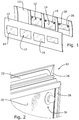
Figure 1 , theside walls 10 of a public transportation vehicle, and more specifically of a rail vehicle, are provided withlateral windows 12, each comprising a set oftransparent panels 14 glazed to awindow frame 16, which itself is received in a window opening of theside wall 10. - As illustrated in
Figures 2 and3 , the set oftransparent panel 14 of eachlateral window 12 includes an innertransparent panel 18, an intermediatetransparent panel 20 and an outertransparent panel 22 adhesively bonded to the intermediatetransparent panel 18. A resilient spacer frame (not shown) ensures that the innertransparent panel 18 and the intermediatetransparent panel 20 are spaced apart so as to define a closedinner space 24 therebetween. Eachtransparent panel transparent panels transparent panels - The
frame 16 of eachlateral window 12 is substantially rectangular and comprises four sides, each formed from amain profile 26 and aclamping profile 28 received in agroove 30 of themain profile 26. Themain profile 26 provides an interface with theside wall 10 of the vehicle. A sealinggasket 32 is provided between the main profile and the side wall of the vehicle. The clampingprofile 28 protrudes from thegroove 30 and has a region of overlap with the innertransparent panel 18. - The inner
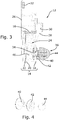
transparent panel 18 has a pair of through holes 34 (only one of which is illustrated inFigure 3 ), which constitute aninlet 36 and anoutlet 38 between theinner space 24 and the outside. Atubular screw 40 protrudes from each throughhole 34. Anut 42 is screwed on a first thread of thetubular screw 40 to fix thetubular screw 40 to the innertransparent panel 18. A threadedcap 44 is engaged on a second thread of thetubular screw 40 to close the protruding open end of thetubular screw 40. - The
inlet 36 is used to fill theinner space 24 with a transparentphotovoltaic gel 46 while the air in theinner space 24 is expelled through theoutlet 38. Once theinner space 24 has been filled with thephotovoltaic gel 46, theinlet 36 andoutlet 38 are closed and sealed with theclosure 44. Theinlet 46 and outlet 48 can be of similar construction or can be different from one another (e.g. to include check valves). - The photovoltaic gel is preferably a sol-gel of Si2Ox in a water matrix.
- As depicted in
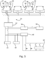
Figure 5 , twoelectrodes 50 are provided on two opposite sides or two opposite corners of theframe 16 and are brought in contact with the transparentphotovoltaic gel 46 in the inner space to electrically connect the transparent photovoltaic gel with anelectrical circuit 51. The pairs ofelectrodes 50 of thelateral windows 12 on one side of the vehicle are connected in parallel with abattery charger controller 52, which is also connected to a set ofbatteries 54, and to a DC/AC inverter 56 to distribute AC power to variousAC power consumers 58 in the vehicle. Thebatteries 54 are connected to abattery discharger controller 60 to distribute DC power to variousDC power consumers 62 in the vehicle. - In the operational state, when the vehicle is in or out of service during daylight hours, the
lateral windows 12 generate electrical power, which is used either to directly feed the DC/AC inverter 56 or to charge thebatteries 54. Peak performances in standard lighting (1000 w/m2) are in the range of 90 to 100 W/m2. The voltage obtained between the electrodes vary from 2 to 3,5 V depending on the thickness of the gel layer. Favourable thicknesses (i.e. distance between inner transparent panel and intermediate transparent panel) range from 4 to 8 mm. - Referring to
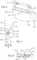
figures 6 to 8 , alateral window 12 according to a second embodiment comprises a set oftransparent panels 14 glazed to awindow frame 16. The set oftransparent panel 14 includes an innertransparent panel 18, an intermediate transparent 20 panel and an outertransparent panel 22 adhesively bonded to the intermediatetransparent panel 18. A resilient spacer frame (not shown) ensures that the innertransparent panel 18 and the intermediatetransparent panel 20 are spaced apart so as to define a closedinner space 24 therebetween. A number ofelectrodes 50 are distributed on the side members 16.1 upper member 16.2 and lower member of the window frame. Eachelectrode 50 consists of a metallic rod, which runs parallel to the associated frame member and is immersed in a transparentphotovoltaic gel 46 that fills in theinner space 24. Some of theelectrodes 50 may be connected with one another. At least two of theelectrodes 50, preferably associated with the upper member 16.2 of theframe 16, are connected to an external circuit similar to thecircuit 51 offigure 5 through abushing 70 and acable 72. Thebushing 70 is illustrated in its final operational state infigure 8. Figure 8 illustrates anopening 74 in the upper frame member 16.2 for accommodating thebushing 70, and anopen bushing housing 76 received in the opening. Theelectrodes 50 comprises a T-shapedend portion 78 which forms a key that can slide in the housing from a free position to a locked position illustrated infigure 8 . Preferably, thewhole electrode 50 is shaped such that it can be inserted into theinner space 24 through thebushing housing 76. Once the T-shapedend portion 78 of the electrode is in the locked position, a sealingcap 80 made of silicone or of a non-cured elastomeric material is injected into the free space between the T-shaped end of the electrode allowed to polymerise to close thebushing 70. - The opening of the bushing housing is used to fill the
inner space 24 of thelateral window 12 with the transparentphotovoltaic gel 46, either before the electrode is put in place, or after the electrode has been inserted in the bushing but before it is locked with the sealingcap 80. As there are at least two such openings, one can be used as inlet to fill theinner space 24 while the other is used as outlet to expel the air from theinner space 24. - While the above examples illustrate preferred embodiments of the present invention it is noted that various other arrangements can also be considered, as long as they belong to the scope defined by the appended set of claims. The
electrical circuit 51 can include any subset oflateral windows 12 on one or both sides of the vehicle body or one more than one vehicle body. The shape of the window can vary.
Claims (15)
- A lateral window (12) for a public transportation vehicle, comprising:- a first transparent panel (18),- a second transparent panel (20) spaced apart from the first transparent panel (18); and- a window frame (16) comprising a main profile (26) for supporting the first transparent panel (18) and the second transparent panel (20), an inner space (24) being defined between the first (18) and second (20) transparent panels and the window frame (16),characterised in that it further comprises a transparent photovoltaic gel (46) filling the inner space (24).
- The lateral window of claim 1, wherein the photovoltaic gel (46) contains a silicon gel and a semiconductor.
- The lateral window of any one of the preceding claims, wherein the photovoltaic gel (46) completely fills the inner space (24).
- The lateral window of any one of the preceding claims, wherein the first (18) and second (20) transparent panels are planar.
- The lateral window of any one of the preceding claims, further comprising a filling arrangement for filling the inner space (24) between the first transparent panel (18) and second transparent panel (20) with the photovoltaic gel (46).
- The lateral window of claim 5, wherein the filing arrangement for filling the inner space (24) comprises a filling inlet (36, 74) for introducing the photovoltaic gel (46) into the inner space (24), a pressure compensation outlet (38, 74) for allowing air to leave the inner space (24) and closure elements (44, 80) for closing the filling inlet (36, 74) and pressure compensation outlet (38,74).
- The lateral window of claim 6, wherein the filling inlet (36) comprises a through hole (34) in the first transparent panel (18).
- The lateral window of claim 6 or claim 7, wherein the pressure compensation outlet (38) comprises a through hole (34) in the first transparent panel (18).
- The lateral window of claim 6, wherein the filling inlet (36, 74) and pressure compensation outlet (38, 74) are arranged in one or more frame members (16.1, 16.2) of the window frame (16).
- The lateral window of any one of the preceding claims, further comprising a pair of electrodes (50) spaced apart from one another for electrically connecting the photovoltaic gel (46) to an outside electrical circuit (51) through the window frame (16).
- The lateral window of claim 10, wherein the electrodes (50) are arranged on the window frame (16).
- The lateral window of claim 11 in combination with claim 9, further comprising at least two openings (74) in the window frame (16), wherein the two openings form the filling inlet (36) and pressure outlet (38) and are closed by bushings that connect the electrodes to the outside circuit (51).
- A photovoltaic power generation system for a public transportation vehicle, characterized in that it includes a set of one or more lateral windows (12) according to any one of claims 10 to 12 and an electrical circuit (51) for connecting the electrodes (50) of the one or more lateral windows (12) to one or more electrical components amongst the following:- a set of one or more batteries (54) ;- one or more DC loads (58); and/or- one or more AC loads (62),wherein the electrical circuit (51) preferably includes a charger controller (52) between the electrodes (50) and the one or more electrical components.
- The photovoltaic power generation system of claim 13, characterized in that the lateral windows (12) are connected in parallel.
- A public transportation vehicle comprising a side wall (10) provided with lateral window openings, and a photovoltaic power generation system according to claim 13 or claim 14, wherein the set of one or more lateral windows (12) of the photovoltaic power generation system are framed into one or more of the window openings.
Priority Applications (5)
| Application Number | Priority Date | Filing Date | Title |
|---|---|---|---|
| EP16171184.1A EP3248854B1 (en) | 2016-05-24 | 2016-05-24 | Lateral photovoltaic window for a public transportation vehicle, associated photovoltaic power generation system and public transportation vehicle |
| US16/304,191 US20200321163A1 (en) | 2016-05-24 | 2017-05-22 | Lateral Photovoltaic Window for a Public Transportation Vehicle, Associated Photovoltaic Power Generation System and Public Transportation Vehicle |
| CN201780043229.5A CN109476326A (en) | 2016-05-24 | 2017-05-22 | Lateral photovoltaic windows for public transport vehicles, associated photovoltaic power generation systems and public transport vehicles |
| CA3025052A CA3025052A1 (en) | 2016-05-24 | 2017-05-22 | Lateral photovoltaic window for a public transportation vehicle, associated photovoltaic power generation system and public transportation vehicle |
| PCT/EP2017/062310 WO2017202791A1 (en) | 2016-05-24 | 2017-05-22 | Lateral photovoltaic window for a public transportation vehicle, associated photovoltaic power generation system and public transportation vehicle |
Applications Claiming Priority (1)
| Application Number | Priority Date | Filing Date | Title |
|---|---|---|---|
| EP16171184.1A EP3248854B1 (en) | 2016-05-24 | 2016-05-24 | Lateral photovoltaic window for a public transportation vehicle, associated photovoltaic power generation system and public transportation vehicle |
Publications (2)
| Publication Number | Publication Date |
|---|---|
| EP3248854A1 EP3248854A1 (en) | 2017-11-29 |
| EP3248854B1 true EP3248854B1 (en) | 2019-11-20 |
Family
ID=56098018
Family Applications (1)
| Application Number | Title | Priority Date | Filing Date |
|---|---|---|---|
| EP16171184.1A Active EP3248854B1 (en) | 2016-05-24 | 2016-05-24 | Lateral photovoltaic window for a public transportation vehicle, associated photovoltaic power generation system and public transportation vehicle |
Country Status (5)
| Country | Link |
|---|---|
| US (1) | US20200321163A1 (en) |
| EP (1) | EP3248854B1 (en) |
| CN (1) | CN109476326A (en) |
| CA (1) | CA3025052A1 (en) |
| WO (1) | WO2017202791A1 (en) |
Families Citing this family (2)
| Publication number | Priority date | Publication date | Assignee | Title |
|---|---|---|---|---|
| CN114394119A (en) * | 2021-11-19 | 2022-04-26 | 中车唐山机车车辆有限公司 | Power generation window and railway passenger car |
| NL2032204B1 (en) * | 2022-06-17 | 2024-01-05 | Lightyear Layer Ipco B V | Integrating a solar panel in a vehicle body part |
Family Cites Families (9)
| Publication number | Priority date | Publication date | Assignee | Title |
|---|---|---|---|---|
| JP2007055861A (en) * | 2005-08-25 | 2007-03-08 | Nippon Sheet Glass Co Ltd | Bending method for automotive glass with conductive film for dye-sensitized solar cell and automotive glass with conductive film for dye-sensitized solar cell |
| DE102009029790A1 (en) * | 2009-06-18 | 2011-05-19 | GM Global Technology Operations, Inc., Detroit | Transport unit i.e. passenger car, has generator layer arranged between anode and cathode and comprising ionic material of titanium oxide or zinc oxide with artificial color pigments as ionic partner for wavelength range of solar radiation |
| KR20110016072A (en) * | 2009-08-11 | 2011-02-17 | 주식회사 동진쎄미켐 | Dye-Sensitized Solar Cells and Modules Composed therefrom |
| CN201663568U (en) * | 2010-04-23 | 2010-12-01 | 刘波 | Solar energy photovoltaic generating set on top cover of railway passenger carriage |
| CN203573992U (en) | 2013-09-12 | 2014-04-30 | 许昌弘日能源有限公司 | Solar double-glass module |
| HUE046960T2 (en) * | 2013-12-04 | 2020-04-28 | Siemens Mobility Austria Gmbh | Passenger compartment side window for a vehicle |
| CN203674228U (en) * | 2014-01-06 | 2014-06-25 | 珠海兴业光电科技有限公司 | Aerogel hollow glass photovoltaic component |
| CN104810420A (en) * | 2014-01-23 | 2015-07-29 | 安阳市方圆钢化玻璃有限责任公司 | Light transmitting crystalline silicon solar cell assembly |
| CN205092592U (en) * | 2015-11-16 | 2016-03-16 | 江苏中圣高科技产业有限公司 | Distributing type photovoltaic power generation and control system |
-
2016
- 2016-05-24 EP EP16171184.1A patent/EP3248854B1/en active Active
-
2017
- 2017-05-22 CN CN201780043229.5A patent/CN109476326A/en active Pending
- 2017-05-22 WO PCT/EP2017/062310 patent/WO2017202791A1/en not_active Ceased
- 2017-05-22 US US16/304,191 patent/US20200321163A1/en not_active Abandoned
- 2017-05-22 CA CA3025052A patent/CA3025052A1/en not_active Abandoned
Non-Patent Citations (1)
| Title |
|---|
| None * |
Also Published As
| Publication number | Publication date |
|---|---|
| WO2017202791A1 (en) | 2017-11-30 |
| CA3025052A1 (en) | 2017-11-30 |
| EP3248854A1 (en) | 2017-11-29 |
| US20200321163A1 (en) | 2020-10-08 |
| CN109476326A (en) | 2019-03-15 |
Similar Documents
| Publication | Publication Date | Title |
|---|---|---|
| AU2012209352B2 (en) | Control system for electrochromic device | |
| US6670541B2 (en) | Solar battery, solar generating apparatus, and building | |
| US20190115638A1 (en) | Battery module with heat dissipating encapsulant material and methods therefor | |
| KR20090035553A (en) | Insulated windows combining photovoltaic cells and pressure balancing systems | |
| CN202788519U (en) | Photovoltaic electrochromic glass window | |
| US12270114B2 (en) | Radiation-assisted electrolyzer cell and panel | |
| EP3248854B1 (en) | Lateral photovoltaic window for a public transportation vehicle, associated photovoltaic power generation system and public transportation vehicle | |
| JP2021512042A (en) | Integrated glazing unit with electronic elements | |
| US20140182651A1 (en) | Integrated junction insulation for photovoltaic module | |
| CN106712696A (en) | Solar module with junction box integrated | |
| CN201433487Y (en) | Solar photovoltaic hollow glass curtain-wall component | |
| CN102808467A (en) | Double insulating glass curtain wall components | |
| CN103165709A (en) | Light solar cell module | |
| CN213638521U (en) | Power supply module with DIN guide rail | |
| CN211428183U (en) | Frameless dual glass assembly | |
| KR101030285B1 (en) | Multilayer Glass Type Dye-Sensitized Solar Cell Module | |
| CN105609579A (en) | Solar photovoltaic composite plate | |
| CN209389048U (en) | a photovoltaic module | |
| CN207765462U (en) | A kind of locking device of solar energy photovoltaic panel | |
| CN211063547U (en) | Solar power generation device for building | |
| KR20140003679A (en) | Manufacturing method for bipv module | |
| JPS5972778A (en) | Solar battery module | |
| CA2748067A1 (en) | Photovoltaic module | |
| JPS58180070A (en) | Solar battery module | |
| CN208045589U (en) | Novel storage battery connection sheet |
Legal Events
| Date | Code | Title | Description |
|---|---|---|---|
| PUAI | Public reference made under article 153(3) epc to a published international application that has entered the european phase |
Free format text: ORIGINAL CODE: 0009012 |
|
| STAA | Information on the status of an ep patent application or granted ep patent |
Free format text: STATUS: THE APPLICATION HAS BEEN PUBLISHED |
|
| AK | Designated contracting states |
Kind code of ref document: A1 Designated state(s): AL AT BE BG CH CY CZ DE DK EE ES FI FR GB GR HR HU IE IS IT LI LT LU LV MC MK MT NL NO PL PT RO RS SE SI SK SM TR |
|
| AX | Request for extension of the european patent |
Extension state: BA ME |
|
| STAA | Information on the status of an ep patent application or granted ep patent |
Free format text: STATUS: REQUEST FOR EXAMINATION WAS MADE |
|
| 17P | Request for examination filed |
Effective date: 20180528 |
|
| RBV | Designated contracting states (corrected) |
Designated state(s): AL AT BE BG CH CY CZ DE DK EE ES FI FR GB GR HR HU IE IS IT LI LT LU LV MC MK MT NL NO PL PT RO RS SE SI SK SM TR |
|
| GRAP | Despatch of communication of intention to grant a patent |
Free format text: ORIGINAL CODE: EPIDOSNIGR1 |
|
| STAA | Information on the status of an ep patent application or granted ep patent |
Free format text: STATUS: GRANT OF PATENT IS INTENDED |
|
| RIC1 | Information provided on ipc code assigned before grant |
Ipc: H02S 40/32 20140101ALI20190426BHEP Ipc: H02S 20/30 20140101ALI20190426BHEP Ipc: H01G 9/20 20060101ALI20190426BHEP Ipc: B61D 25/00 20060101AFI20190426BHEP Ipc: H01L 31/048 20140101ALI20190426BHEP |
|
| INTG | Intention to grant announced |
Effective date: 20190531 |
|
| GRAS | Grant fee paid |
Free format text: ORIGINAL CODE: EPIDOSNIGR3 |
|
| GRAA | (expected) grant |
Free format text: ORIGINAL CODE: 0009210 |
|
| STAA | Information on the status of an ep patent application or granted ep patent |
Free format text: STATUS: THE PATENT HAS BEEN GRANTED |
|
| AK | Designated contracting states |
Kind code of ref document: B1 Designated state(s): AL AT BE BG CH CY CZ DE DK EE ES FI FR GB GR HR HU IE IS IT LI LT LU LV MC MK MT NL NO PL PT RO RS SE SI SK SM TR |
|
| REG | Reference to a national code |
Ref country code: GB Ref legal event code: FG4D |
|
| REG | Reference to a national code |
Ref country code: CH Ref legal event code: EP |
|
| REG | Reference to a national code |
Ref country code: IE Ref legal event code: FG4D |
|
| REG | Reference to a national code |
Ref country code: DE Ref legal event code: R096 Ref document number: 602016024532 Country of ref document: DE |
|
| REG | Reference to a national code |
Ref country code: AT Ref legal event code: REF Ref document number: 1203858 Country of ref document: AT Kind code of ref document: T Effective date: 20191215 |
|
| REG | Reference to a national code |
Ref country code: CH Ref legal event code: NV Representative=s name: TR-IP CONSULTING LLC, CH |
|
| REG | Reference to a national code |
Ref country code: NL Ref legal event code: MP Effective date: 20191120 |
|
| REG | Reference to a national code |
Ref country code: LT Ref legal event code: MG4D |
|
| PG25 | Lapsed in a contracting state [announced via postgrant information from national office to epo] |
Ref country code: LV Free format text: LAPSE BECAUSE OF FAILURE TO SUBMIT A TRANSLATION OF THE DESCRIPTION OR TO PAY THE FEE WITHIN THE PRESCRIBED TIME-LIMIT Effective date: 20191120 Ref country code: SE Free format text: LAPSE BECAUSE OF FAILURE TO SUBMIT A TRANSLATION OF THE DESCRIPTION OR TO PAY THE FEE WITHIN THE PRESCRIBED TIME-LIMIT Effective date: 20191120 Ref country code: NO Free format text: LAPSE BECAUSE OF FAILURE TO SUBMIT A TRANSLATION OF THE DESCRIPTION OR TO PAY THE FEE WITHIN THE PRESCRIBED TIME-LIMIT Effective date: 20200220 Ref country code: GR Free format text: LAPSE BECAUSE OF FAILURE TO SUBMIT A TRANSLATION OF THE DESCRIPTION OR TO PAY THE FEE WITHIN THE PRESCRIBED TIME-LIMIT Effective date: 20200221 Ref country code: FI Free format text: LAPSE BECAUSE OF FAILURE TO SUBMIT A TRANSLATION OF THE DESCRIPTION OR TO PAY THE FEE WITHIN THE PRESCRIBED TIME-LIMIT Effective date: 20191120 Ref country code: LT Free format text: LAPSE BECAUSE OF FAILURE TO SUBMIT A TRANSLATION OF THE DESCRIPTION OR TO PAY THE FEE WITHIN THE PRESCRIBED TIME-LIMIT Effective date: 20191120 Ref country code: NL Free format text: LAPSE BECAUSE OF FAILURE TO SUBMIT A TRANSLATION OF THE DESCRIPTION OR TO PAY THE FEE WITHIN THE PRESCRIBED TIME-LIMIT Effective date: 20191120 Ref country code: BG Free format text: LAPSE BECAUSE OF FAILURE TO SUBMIT A TRANSLATION OF THE DESCRIPTION OR TO PAY THE FEE WITHIN THE PRESCRIBED TIME-LIMIT Effective date: 20200220 |
|
| PG25 | Lapsed in a contracting state [announced via postgrant information from national office to epo] |
Ref country code: IS Free format text: LAPSE BECAUSE OF FAILURE TO SUBMIT A TRANSLATION OF THE DESCRIPTION OR TO PAY THE FEE WITHIN THE PRESCRIBED TIME-LIMIT Effective date: 20200320 Ref country code: HR Free format text: LAPSE BECAUSE OF FAILURE TO SUBMIT A TRANSLATION OF THE DESCRIPTION OR TO PAY THE FEE WITHIN THE PRESCRIBED TIME-LIMIT Effective date: 20191120 Ref country code: RS Free format text: LAPSE BECAUSE OF FAILURE TO SUBMIT A TRANSLATION OF THE DESCRIPTION OR TO PAY THE FEE WITHIN THE PRESCRIBED TIME-LIMIT Effective date: 20191120 |
|
| PG25 | Lapsed in a contracting state [announced via postgrant information from national office to epo] |
Ref country code: AL Free format text: LAPSE BECAUSE OF FAILURE TO SUBMIT A TRANSLATION OF THE DESCRIPTION OR TO PAY THE FEE WITHIN THE PRESCRIBED TIME-LIMIT Effective date: 20191120 |
|
| PG25 | Lapsed in a contracting state [announced via postgrant information from national office to epo] |
Ref country code: PT Free format text: LAPSE BECAUSE OF FAILURE TO SUBMIT A TRANSLATION OF THE DESCRIPTION OR TO PAY THE FEE WITHIN THE PRESCRIBED TIME-LIMIT Effective date: 20200412 Ref country code: RO Free format text: LAPSE BECAUSE OF FAILURE TO SUBMIT A TRANSLATION OF THE DESCRIPTION OR TO PAY THE FEE WITHIN THE PRESCRIBED TIME-LIMIT Effective date: 20191120 Ref country code: DK Free format text: LAPSE BECAUSE OF FAILURE TO SUBMIT A TRANSLATION OF THE DESCRIPTION OR TO PAY THE FEE WITHIN THE PRESCRIBED TIME-LIMIT Effective date: 20191120 Ref country code: EE Free format text: LAPSE BECAUSE OF FAILURE TO SUBMIT A TRANSLATION OF THE DESCRIPTION OR TO PAY THE FEE WITHIN THE PRESCRIBED TIME-LIMIT Effective date: 20191120 Ref country code: ES Free format text: LAPSE BECAUSE OF FAILURE TO SUBMIT A TRANSLATION OF THE DESCRIPTION OR TO PAY THE FEE WITHIN THE PRESCRIBED TIME-LIMIT Effective date: 20191120 Ref country code: CZ Free format text: LAPSE BECAUSE OF FAILURE TO SUBMIT A TRANSLATION OF THE DESCRIPTION OR TO PAY THE FEE WITHIN THE PRESCRIBED TIME-LIMIT Effective date: 20191120 |
|
| REG | Reference to a national code |
Ref country code: DE Ref legal event code: R097 Ref document number: 602016024532 Country of ref document: DE |
|
| PG25 | Lapsed in a contracting state [announced via postgrant information from national office to epo] |
Ref country code: SM Free format text: LAPSE BECAUSE OF FAILURE TO SUBMIT A TRANSLATION OF THE DESCRIPTION OR TO PAY THE FEE WITHIN THE PRESCRIBED TIME-LIMIT Effective date: 20191120 Ref country code: SK Free format text: LAPSE BECAUSE OF FAILURE TO SUBMIT A TRANSLATION OF THE DESCRIPTION OR TO PAY THE FEE WITHIN THE PRESCRIBED TIME-LIMIT Effective date: 20191120 |
|
| PLBE | No opposition filed within time limit |
Free format text: ORIGINAL CODE: 0009261 |
|
| STAA | Information on the status of an ep patent application or granted ep patent |
Free format text: STATUS: NO OPPOSITION FILED WITHIN TIME LIMIT |
|
| REG | Reference to a national code |
Ref country code: AT Ref legal event code: UEP Ref document number: 1203858 Country of ref document: AT Kind code of ref document: T Effective date: 20191120 |
|
| 26N | No opposition filed |
Effective date: 20200821 |
|
| PG25 | Lapsed in a contracting state [announced via postgrant information from national office to epo] |
Ref country code: SI Free format text: LAPSE BECAUSE OF FAILURE TO SUBMIT A TRANSLATION OF THE DESCRIPTION OR TO PAY THE FEE WITHIN THE PRESCRIBED TIME-LIMIT Effective date: 20191120 Ref country code: PL Free format text: LAPSE BECAUSE OF FAILURE TO SUBMIT A TRANSLATION OF THE DESCRIPTION OR TO PAY THE FEE WITHIN THE PRESCRIBED TIME-LIMIT Effective date: 20191120 |
|
| REG | Reference to a national code |
Ref country code: DE Ref legal event code: R119 Ref document number: 602016024532 Country of ref document: DE |
|
| PG25 | Lapsed in a contracting state [announced via postgrant information from national office to epo] |
Ref country code: LI Free format text: LAPSE BECAUSE OF NON-PAYMENT OF DUE FEES Effective date: 20200531 Ref country code: MC Free format text: LAPSE BECAUSE OF FAILURE TO SUBMIT A TRANSLATION OF THE DESCRIPTION OR TO PAY THE FEE WITHIN THE PRESCRIBED TIME-LIMIT Effective date: 20191120 Ref country code: CH Free format text: LAPSE BECAUSE OF NON-PAYMENT OF DUE FEES Effective date: 20200531 Ref country code: IT Free format text: LAPSE BECAUSE OF FAILURE TO SUBMIT A TRANSLATION OF THE DESCRIPTION OR TO PAY THE FEE WITHIN THE PRESCRIBED TIME-LIMIT Effective date: 20191120 |
|
| REG | Reference to a national code |
Ref country code: BE Ref legal event code: MM Effective date: 20200531 |
|
| GBPC | Gb: european patent ceased through non-payment of renewal fee |
Effective date: 20200524 |
|
| PG25 | Lapsed in a contracting state [announced via postgrant information from national office to epo] |
Ref country code: LU Free format text: LAPSE BECAUSE OF NON-PAYMENT OF DUE FEES Effective date: 20200524 |
|
| PG25 | Lapsed in a contracting state [announced via postgrant information from national office to epo] |
Ref country code: FR Free format text: LAPSE BECAUSE OF NON-PAYMENT OF DUE FEES Effective date: 20200531 Ref country code: IE Free format text: LAPSE BECAUSE OF NON-PAYMENT OF DUE FEES Effective date: 20200524 Ref country code: GB Free format text: LAPSE BECAUSE OF NON-PAYMENT OF DUE FEES Effective date: 20200524 |
|
| PG25 | Lapsed in a contracting state [announced via postgrant information from national office to epo] |
Ref country code: BE Free format text: LAPSE BECAUSE OF NON-PAYMENT OF DUE FEES Effective date: 20200531 Ref country code: DE Free format text: LAPSE BECAUSE OF NON-PAYMENT OF DUE FEES Effective date: 20201201 |
|
| PGFP | Annual fee paid to national office [announced via postgrant information from national office to epo] |
Ref country code: AT Payment date: 20210520 Year of fee payment: 6 |
|
| PG25 | Lapsed in a contracting state [announced via postgrant information from national office to epo] |
Ref country code: TR Free format text: LAPSE BECAUSE OF FAILURE TO SUBMIT A TRANSLATION OF THE DESCRIPTION OR TO PAY THE FEE WITHIN THE PRESCRIBED TIME-LIMIT Effective date: 20191120 Ref country code: MT Free format text: LAPSE BECAUSE OF FAILURE TO SUBMIT A TRANSLATION OF THE DESCRIPTION OR TO PAY THE FEE WITHIN THE PRESCRIBED TIME-LIMIT Effective date: 20191120 Ref country code: CY Free format text: LAPSE BECAUSE OF FAILURE TO SUBMIT A TRANSLATION OF THE DESCRIPTION OR TO PAY THE FEE WITHIN THE PRESCRIBED TIME-LIMIT Effective date: 20191120 |
|
| PG25 | Lapsed in a contracting state [announced via postgrant information from national office to epo] |
Ref country code: MK Free format text: LAPSE BECAUSE OF FAILURE TO SUBMIT A TRANSLATION OF THE DESCRIPTION OR TO PAY THE FEE WITHIN THE PRESCRIBED TIME-LIMIT Effective date: 20191120 |
|
| REG | Reference to a national code |
Ref country code: AT Ref legal event code: MM01 Ref document number: 1203858 Country of ref document: AT Kind code of ref document: T Effective date: 20220524 |
|
| PG25 | Lapsed in a contracting state [announced via postgrant information from national office to epo] |
Ref country code: AT Free format text: LAPSE BECAUSE OF NON-PAYMENT OF DUE FEES Effective date: 20220524 |